

Autonics PRDA Series Catalog Page
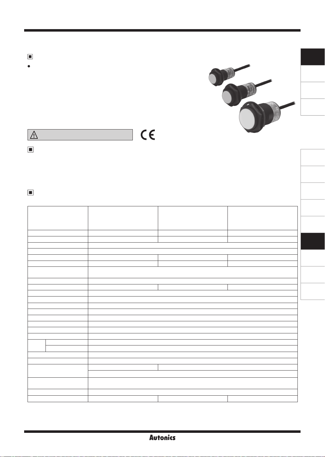
PRDA Series
Cylindrical, Long Sensing Distance, Spatter-Resistance, Cable Type
Features
Long sensing distance
•
(1.5 to 2 times longer sensing distance guaranteed
compared to existing models)
● Prevent malfunction due to welding spatter with PEFE coating
● Improved the noise immunity with dedicated IC
● Built-in surge protection, output short over current protection circuit
● Red LED operation indication
● IP67 protection structure (IEC standard)
● Replaceable for spatter-resistance type limit switches
Please read “Safety Considerations”
in the instruction manual before using.
=I
&c....___
___
___.l
CE:
SENSORS
CONTROLLERS
MOTION DEVICES
SOFTWARE
The Characteristic of Spatter-Resistance Type
The hot arc from arc welding machine is adhesive even with metals or plastics.
Therefore, normal proximity sensor might have malfunction even though there are no sensing object if the arcs are put on
the sensing surface. The arcs are not adhered on the sensing part of the spatter-resistance type proximity sensor as the
part is coated with PEFE against thermal resistance.
Also, the protection cover sold optionally has the same function.
Specifications
● DC 2-wire type
PRDAT12-4DO
Model
Diameter of the sensing side 12mm 18mm 30mm
Sensing distance 4mm 7mm 15mm
Installation Shield (ush)
Hysteresis Max. 10% of sensing distance
Standard sensing target 12×12×1mm (iron) 20×20×1mm (iron) 45×45×1mm (iron)
Setting distance 0 to 2.8mm 0 to 4.9mm 0 to 10.5mm
Power supply
(opera ing voltage)
Leakage current Max. 0.6mA
Response frequency
Residual voltage Max. 3.5V
Aection by Temp. Max. ±10% for sensing distance at ambient temperature 20℃
Control output 2 to 100mA
Insulation resistance Over 50MΩ (at 500VDC megger)
Dielectric strength 1,500VAC 50/60Hz for 1 min
Vibra ion 1mm amplitude at frequency 10 to 55Hz (for 1 min) in each X, Y, Z direction for 2 hours
Shock 500m/s² (approx. 50G) in each X, Y, Z direction for 3 times
Indicator Operation indicator: Red LED
Ambient temperature -25 to 70℃, storage: -30 to 80
I
Environment
Ambient humidity 35 to 95%RH, storage: 35 to 95%RH
I
Protec ion circuit Surge protection circuit, output short over current protection circuit
Protec ion structure IP67 (IEC standard)
Cable
Material
Approval
2
※
Weight
※
1: The response frequency is the average value. The standard sensing target is used and the width is set as 2 imes of the standard
sensing target, 1/2 of the sensing distance for the distance.
※
2: The weight includes packaging. The weight in parenthesis in for unit only.
※
Environment resistance is rated at no freezing or condensation.
※
PRDAT12-4DC
PRDAT12-4DO-V
PRDAT12-4DC-V
12-24VDC
(10-30VDCᜡ)
1
450Hz 250Hz 100Hz
Ø4mm, 2-wire, 2m, M12 connector
AWG22, Core diameter: 0.8mm, Number of cores: 60, Insulator diameter: Ø1.25mm
Case/Nut: PEFE coated brass, Washer: PEFE coated iron, Sensing surface: PEFE,
Standard cable (black): Polyvinyl chloride (PVC), Oil resistant cable (gray): Oil resistant polyvinyl chloride (PVC)
ᜢ
Approx. 84g (approx. 72g) Approx. 134g (approx. 122g) Approx. 221g (approx. 184g)
ᜡ
PRDAT18-7DO
PRDAT18-7DC
PRDAT18-7DO-V
PRDAT18-7DC-V
℃
Ø5mm, 2-wire, 2m, M12 connector
PRDAT30-15DO
PRDAT30-15DC
PRDAT30-15DO-V
PRDAT30-15DC-V
(A)
Photoelectric
Sensors
(B)
Fiber Optic
Sensors
(C)
LiDAR
(D)
Door/Area
Sensors
(E)
Vision
Sensors
(F)
Proximity
Sensors
(G)
Pressure
Sensors
(H)
Rotary
Encoders
(I)
Connectors/
Connector Cables/
Sensor Distribution
Boxes/ Sockets
Autonics
F-145
PRDA Series
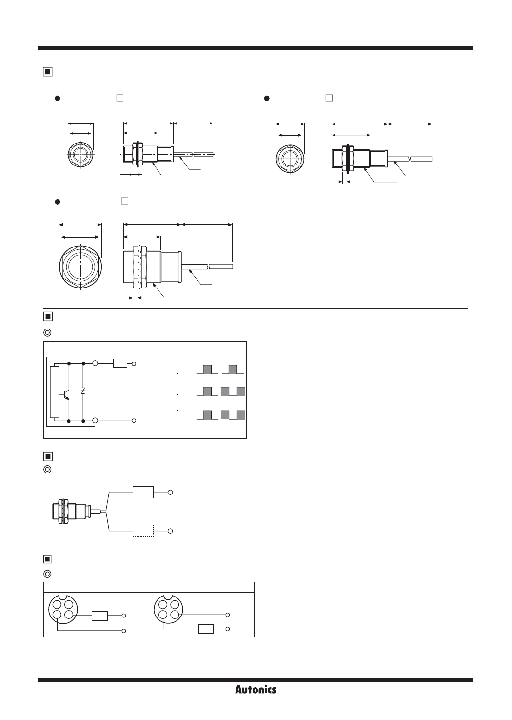
Dimensions
~
PRDAT12-4D
•
Ø21
17
□
1:
•
l
2000
·1
43
32
'I
ij
4
~
PRDAT30-15D
•
Ø42
35
□
58 5
38.5
5
Control Output Diagram and Load Operation
DC 2-wire type
M12×1
M30×1.5
Ø4
2000
Ø5
PRDAT18-7D
Ø29
24
i
□
47.5
29.5
1:
- - - -
4
--1L
·1
T
M18×1
2000
Ø5
(unit: mm)
. I
Main circuit
Brown
Blue
Load
+V
0V
Sensing
target
Load
Operation
Indicator
(red LED)
Presence
None
Operat on
Return
ON
OFF
N.O.
N.C.
Connections
DC 2-wire type
Brown
Blue
Load
Load
:
~
+24VDC
0V
※
For using DC 2-wire type, connect load before suppling the power
and using this unit, or inner element may be damaged.
※
The load can be connected to either wire.
Wiring Diagram
DC 2-wire type (standard type)
Normally Open (N.O.) / Normally Closed (N.C.)
231
※
※
Brown
4
Load
Blue
Pin ①, ② are not used terminals.
When using DC 3-wire type of connector cable, black (12-24VDC) and blue (0V) cables can be used.
+V
0V
231
Brown
4
Blue
Load
+V
0V
F-146
Autonics
 Loading...