

Page 1
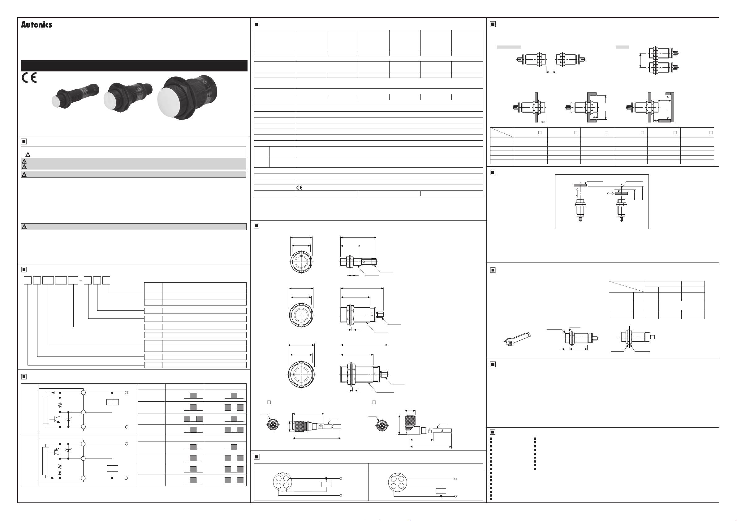
DRW171492AA
INDUCTIVE PROXIMITY SENSOR
(Spatter Resistant DC 3-wire Connector Type)
PRACM/PRDACM SERIES
I N S T R U C T I O N M A N U A L
Thank you for choosing our Autonics products.
Please read the following safety considerations before use.
Safety Considerations
Please observe all safety considerations for safe and proper product operation to avoid hazards.
※
※
symbol represents caution due to special circumstances in which hazards may occur.
Warning Failure to follow these instructions may result in serious injury or death.
Caution
Failure to follow these instructions may result in personal injury or product damage.
Warning
1. Fail-safe device must be installed when using the unit with machinery that may cause serious injury or substantial
economic loss. (e.g. nuclear power control, medical equipment, ships, vehicles, railways, aircraft, combustion apparatus,
safety equipment, crime/disaster prevention devices, etc.)
Failure to follow this instruction may result in re, personal injury, or economic loss.
2. Do not disassemble or modify the unit.
Failure to follow this instruction may result in re.
3. Do not connect, repair, or inspect the unit while connected to a power source.
Failure to follow this instruction may result in re.
4. Check 'Connections' before wiring.
Failure to follow this instruction may result in re.
Caution
1. Use the unit within the rated specications.
Failure to follow this instruction may result in re or product damage.
2. Use dry cloth to clean the unit, and do not use water or organic solvent.
Failure to follow this instruction may result in re.
3. Do not use the unit in the place where ammable/explosive/corrosive gas, humidity, direct sunlight, radiant heat, vibration,
impact, or salinity may be present.
Failure to follow this instruction may result in re or explosion.
Ordering Information
R 5 D NCMDAP 18
Output
Power supply
Sensing distance
Dimension
Connection
Feature
Shape
Item
Control Output Diagram and Load Operation
Brown
1
NPN
output
type
Main circuit
PNP
output
type
Main circuit
The above specications are subject to change and some models may be discontinued without notice.
※
Be sure to follow cautions written in the instruction manual and the technical descriptions (catalog, homepage).
※
10k
10k
Ω
Black
4
Blue
3
Brown
1
Black
4
Ω
Blue
3
Load
Load
N NPN Normally Open (N.O.)
N2 NPN Normally Closed (N.C.)
P PNP Normally Open (N.O.)
P2 PNP Normally Closed (N.C.)
D 12-24VDC
Number Standard sensing distance (unit: mm)
Number Diameter of head (unit: mm)
CM DC 3-wire connector type
A Spatter resistant type
DA Long sensing distance spatter resistant type
R Cylindrical type
P Inductive proximity sensor
Normally Open Normally Closed
+V
Sensing
target
Load
(brown-black)
Output voltage
(black-blue)
0V
Operation indicator
(red LED)
Presence
Nothing
Operation
Return
ON
OFF
Presence
H
L
Operation
Normally Open Normally Closed
+V
Sensing
target
Load
(black-blue)
Output voltage
(black-blue)
0V
Operation indicator
(red LED)
Presence
Nothing
Operation
Return
ON
OFF
Presence
H
L
Operation
Nothing
Return
ON
OFF
Nothing
Return
ON
OFF
H
L
H
L
Specications
PRACM12-2DN
Model
PRACM12-2DP
PRACM12-2DN2
PRACM12-2DP2
Sensing distance 2mm 4mm 5mm 7mm 10mm 15mm
Hysteresis Max. 10% of sensing distance
Standard sensing
target
12×12×1mm (iron)
Setting distance 0 to 1.4mm 0 to 2.8mm 0 to 3.5mm 0 to 4.9mm 0 to 7mm 0 to 10.5mm
Power supply
(operating voltage)
Current consumption Max. 10mA
Response frequency
12-24VDC
(10-30VDCᜡ)
1
※
1.5kHz 500Hz 500Hz 300Hz 400Hz 100Hz
Residual voltage Max. 1 5V
Affection by temp. Max. ±10% for sensing distance at ambient temperature 20
Control output Max. 200mA
Insula ion resistance Min. 500MΩ (at 500VDC megger)
Dielectric strength 1,500VAC 50/60Hz for 1 minute
Vibration
1mm amplitude at frequency of 10 to 55Hz in each X, Y, Z direction for 2 hours
Shock 500m/s
Indicator Operation indicator (red LED)
Environ
-ment
Ambient
temperature
Ambient
humidity
-25 to 70℃, storage: -30 to 80
35 to 95%RH, storage: 35 to 95%RH
Protection circuit Surge protection circuit, Reverse polarity protection circuit, Overcurrent protection circuit
Protection IP67 (IEC standards)
Materials Case/Nut: Teon coated brass, Washer: Teon coated iron, Sensing surface: Teon
Approval
2
※
Weight
1: The response frequency is the average value. The standard sensing target is used and the wid h is set as 2 times of the
※
standard sensing target, 1/2 of the sensing distance for the distance.
2: The weight includes packaging. The weight in parentheses is for unit only.
※
※
Environment resistance is rated at no freezing or condensation.
Approx. 38g (approx. 26g) Approx. 61g (approx. 49g) Approx. 146g (approx. 134g)
Dimensions
●
PR(D)ACM12
●
PR(D)ACM18
●
PR(D)ACM30
● Connection cable (sold separately)
●
CID3-
M12
(DC)
Ø21
17
Ø29
24
Ø42
35
40
Ø14 8
※
"L" Standard cable length is 2m, 5m.
PRDACM12-4DN
PRDACM12-4DP
PRDACM12-4DN2
PRDACM12-4DP2
PRACM18-5DN
PRACM18-5DP
PRACM18-5DN2
PRACM18-5DP2
18×18×1mm
(iron)
PRDACM18-7DN
PRDACM18-7DP
PRDACM18-7DN2
PRDACM18-7DP2
20×20×1mm
(iron)
ᜡ
2
(approx. 50G) in each X, Y, Z direction for 3 times
℃
56.3
32
M12×1
M12×1
4
54.3
29.5
4
64 3
38.5
5
●
CLD3-
Ø5
L
M12
M12×1
M18×1
M30×1.5
(DC)
M12×1
27.5
℃
Ø14 8
PRACM30-10DN
PRACM30-10DP
PRACM30-10DN2
PRACM30-10DP2
30×30×1mm
(iron)
Ø5
32
L
PRDACM30-15DN
PRDACM30-15DP
PRDACM30-15DN2
PRDACM30-15DP2
45×45×1mm
(iron)
(unit: mm)
Wiring Diagram
NPN output type PNP output type
2 1
3
Blue
Brown
4
Black
Load
+V
0V
Brown
2
1
Black
4
3
Blue
Load
+V
0V
Mutual-interference and Inuence By Surrounding Metals
Mutual-interference
◎
When several proximity sensors are mounted closely, malfunction of sensor may be caused due to mutual interference.
Therefore, be sure to provide a minimum distance between he two sensors with referring to he chart below.
Face to Face Parallel
B
A
Influence by surrounding metals
◎
When sensors are mounted on metallic panel, it is required to protect the sensors from being affected by any metallic object
except target. Therefore, be sure to provide a minimum distance as below chart.
m
ød
ℓ
Model
tem
A 12 24 30 42 60 90
B 24 24 36 36 60 60
ℓ 0 0 0 0 0 0
ød 12 12 18 18 30 30
m 6 12 15 21 30 45
n 18 18 27 27 45 45
PRACM12-2D
PRDACM12-4D PRACM18-5D PRDACM18-7D PRACM30-10D PRDACM30-15D
ℓ
n
ℓ
(unit: mm)
Setting Distance
Target
Moving
direction
● Sensing distance can be changed by the shape, size or material of the target.
Check he sensing distance like (a), then pass the target within range of setting distance (Sa).
● Setting distance (Sa) : Sensing distance (Sn) × 70%
Installation and Tightening Torque
When tightening the nut, use the provided washer as [Figure 1]
When installing the product, the tightening torque of the nut varies
according to the distance from the fore-end.
The front part of the product is from the fore-end to the dimension on
the below table, and the rear part is from the tip of the nut to the end
of the product. [Figure 2]
In case the nut is placed in the front part of the product, apply
tightening torque for front part.
[Table 1] the allowable tightening torque table is for inserting the
washer as [Figure 3].
[Figure 1]
E.g.) PRACM30-10DN
Setting distance (Sa) = 10mm × 0.7 = 7mm
[Figure 2] [Figure 3]
Fore-end
Nut tip
Front Rear
Sn: Sensing distance
{
Sa: Setting distance
(70% of Sn)
(a)
Moving
direction
[Table 1]
Model
PR(D)ACM12
Series
PR(D)ACM18
Series
PR(D)ACM30
Series
Washer
Target
Sn
Sa
(b)
Strength
Front Rear
Size Torque Torque
13mm 6 37N.m 11.76N m
Flush
-
14.7N.m
26mm 49N.m 78.4N m
Mounting
bracket
Caution During Use
1. Follow instructions in 'Cautions during Use'. Otherwise, it may cause unexpected accidents.
2. 12-24VDC power supply should be insulated and limited voltage/current or Class 2, SELV power supply device.
3. Use the product, after 0.8 sec of supplying power.
4. Wire as short as possible and keep away from high voltage lines or power lines, to prevent surge and inductive noise.
Do not use near the equipment which generates strong magnetic force or high frequency noise (transceiver, etc.).
In case installing the product near the equipment which generates strong surge (motor, welding machine, etc.), use diode or varistor to remove
surge.
5. If the surface of the product is rubbed with a hard object, PTFE coating can be worn out.
6. This unit may be used in the following environments.
Indoors (in the environment condition rated in 'Specications')
①
Altitude max. 2,000m
②
Pollution degree 2
③
Installation category II
④
Major Products
Photoelectric Sensors Temperature Controllers
Fiber Optic Sensors Temperature/Humidity Transducers
Door Sensors SSRs/Power Controllers
Door Side Sensors Counters
Area Sensors Timers
Proximity Sensors Panel Meters
Pressure Sensors Tachometers/Pulse (Rate) Meters
Rotary Encoders Display Units
Connector/Sockets Sensor Controllers
Switching Mode Power Supplies
Control Switches/Lamps/Buzzers
I/O Terminal Blocks & Cables
Stepper Motors/Drivers/Motion Controllers
Graphic/Logic Panels
Field Network Devices
Laser Marking System (Fiber, Co₂, Nd:yag)
Laser Welding/cutting System
DRW171492AA
 Loading...