

Autonics PRAW Series Catalog Page

PRAW Series
Cylindrial, Spatter-Resistance, Cable Connector Type
Features
●
Prevent malfunction due to welding spatter with
PTFE coating
● Improved the noise immunity with dedicated IC
● Built-in surge protection circuit
● Built-in output short over current protection circuit
● IP67 protection structure (IEC standard)
● Replaceable for spatter-resistance type limit switches
Please read “Safety Considerations” in operation
manual before using.
.___I &
____
The Characteristic of Spatter-Resistance Type
~
The hot arc from arc welding machine is adhesive even with metals or plastics.
Therefore, normal proximity sensor might have malfunction even though there are no sensing object if the arcs are put on
the sensing surface. The arcs are not adhered on the sensing part of the spatter-resistance type proximity sensor as the
part is coated with PTFE against thermal resistance.
Also, the protection cover sold optionally has the same function.
Specifications
● DC 2-wire type
PRAWT12-2
Model
Diameter of the sensing side 12mm 18mm 30mm
Sensing distance 2mm 5mm 10mm
Installation Shield (ush)
Hysteresis Max. 10% of sensing distance
Standard sensing target 12×12×1mm (iron) 18×18×1mm (iron) 30×30×1mm (iron)
Setting distance 0 to 1.4mm 0 to 3.5mm 0 to 7mm
Power supply
(operating voltage)
Leakage current Max. 0.6mA
Response frequency
Residual voltage
Aection by Temp. Max. ±10% for sensing distance at ambient temperature 20℃
Control output 2 to 100mA
Insulation resistance Over 50MΩ (at 500VDC megger)
Dielectric strength 1,500VAC 50/60Hz for 1 min (between all terminals and case)
Vibration 1mm amplitude at frequency 10 to 55Hz (for 1 min) in each X, Y, Z direction for 2 hours
Shock 500m/s² (approx. 50G) in each X, Y, Z direction for 3 times
Indicator Operation indicator: Red LED
Environ-
ment
Protection circuit Surge protec ion circuit, output short over current protection circuit
Protection structure IP67 (IEC standard)
Cable
Material
Approval
3
※
Weight
※
1: The response frequency is the average value. The standard sensing target is used and the width is set as 2 times of the standard
sensing target, 1/2 of the sensing distance for the distance.
※
2: Before using non-polarity type, check the condition of connected divice because residual voltage is 5V.
※
3: The weight includes packaging. The weight in parenthesis in for unit only.
※
For more information about cable and specication, refer to the
※
The
□
※
Environment resistance is rated at no freezing or condensation.
2
※
Ambient temperature
I
Ambient humidity
I
of model name is for power type. 'D' is 12-24VDC, 'X' is non-polarity 12-24VDC.
F-134
PRAWT12-2
PRAWT12-2
PRAWT12-2
12-24VDC
(10-30VDCᜡ)
1
※
1.5kHz 500Hz 400Hz
Max. 3.5V (non-polarity type is max. 5V)
-25 to 70℃, storage: -30 to 80
35 to 95%RH, storage: 35 to 95%RH
Ø4mm, 2-wire, 300mm, M12 connector
AWG22, Core diameter: 0.8mm, Number of cores: 60, Insulator diameter: Ø1.25mm
Case/Nut: PTFE coated brass, Washer: PTFE coated iron, Sensing surface: PTFE,
Standard cable (black): Polyvinyl chloride (PVC)
CE
Approx. 54g (approx. 42g) Approx. 70g (approx. 58g) Approx. 134g (approx. 122g)
ᜡ
D
C
□
D
O
□
D
C-I
□
D
O-I
□
___.I
CE:
※
When the
D
PRAWT18-5
PRAWT18-5
PRAWT18-5
PRAWT18-5
℃
Ø5mm, 2-wire, 300mm, M12 connector
(I) Connectors/Cable Connectors/Sensor Distribution Boxes/Sockets
O
□
D
C
□
D
O-I
□
D
C-I
□
Autonics
model name is X, it is non-polarity model.
□
PRAWT30-10
PRAWT30-10
PRAWT30-10
PRAWT30-10
D
O
□
D
C
□
D
O-I
□
D
C-I
□
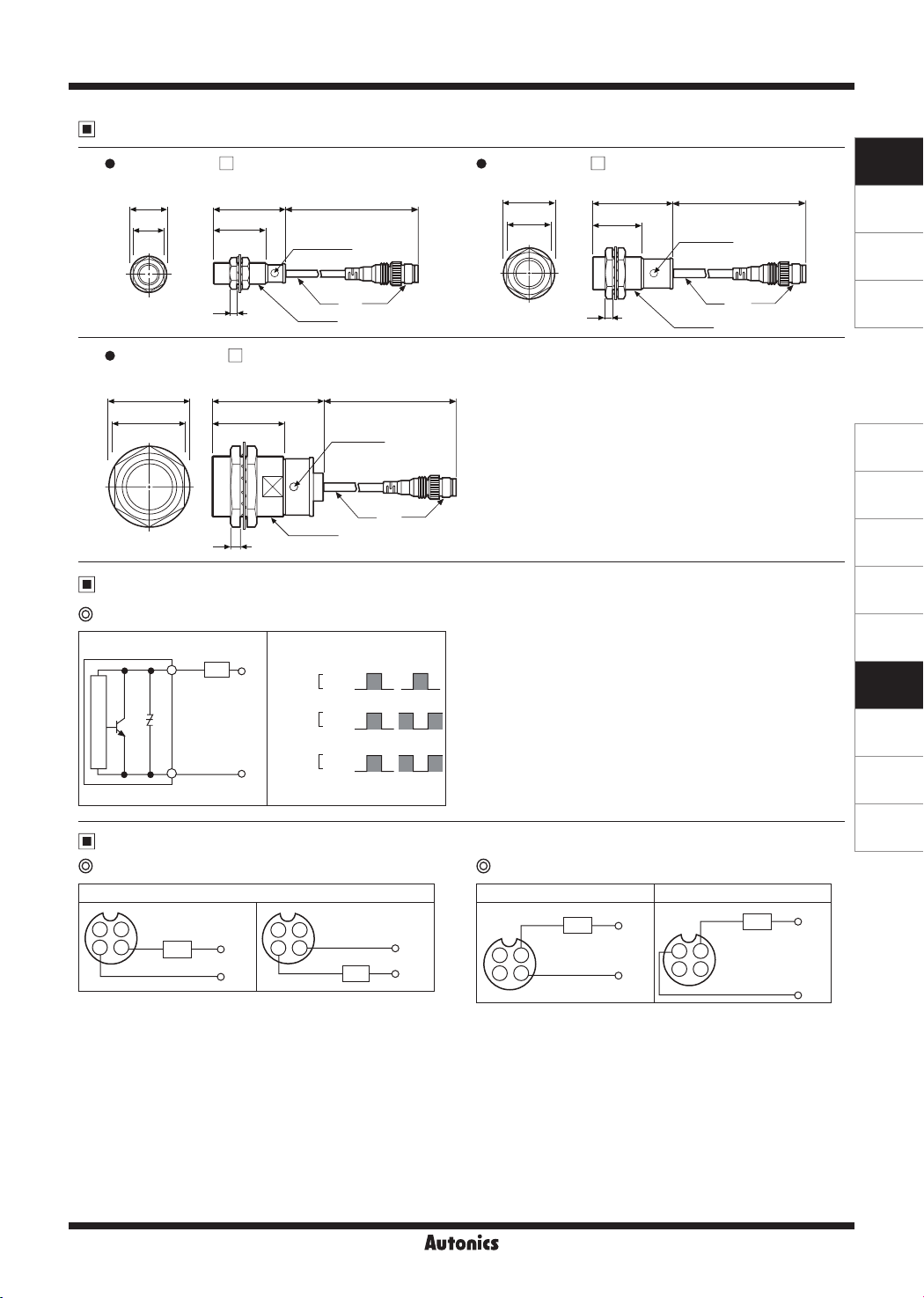
Cylindrial, Spatter-Resistance, Cable Connector Type
Dimensions
PRAWT12-2D PRAWT18-5D
•
Ø21
17
PRAWT30-10D
•
Ø42
35
E;]
~
□
43
32
4
□
58 5
38.5
5
__JJ,_
Operation
indicator
M12×1
M30×1 5
Ø4
300
M12
Operation
indicator
Ø5
300
M12
•
Ø29
□
Operation
indicator
Ø5
300
47.5
24
29.5
4
M18×1
Control Output Diagram and Load Operation
DC 2-wire type
Main circuit
Brown
Blue
Load
+V
0V
Sensing
target
Load
Operation
Indicator
(red LED)
Presence
[
None
Operation
[
Return
ON
[
OFF
N.O.
_O_
_O_
N.C.
Wiring Diagram
DC 2-wire type (standard type) DC 2-wire type (IEC standard type)
Normally Open (N.O.) / Normally Closed (N.C )
1
2
※
Brown
3
4
Blue
are not used terminals.
①, ②
Load
231
+V
0V
Brown
4
Blue
Load
+V
0V
Normally Open (N.O.) Normally Closed (N.C.)
Brown
Load
2
Blue
314
※
of N.O. type and ③,④ of N.C. type are not used terminals.
②,③
※
The pin arrangement of connector applying IEC standard is being
developed.
※
Please attach "I" at he end of he name of standard type for
purchasing he IEC standard product.
E.g ) PRAWT12-2DO-I
※
The connector cable for IEC standard is being developed.
Please attach "I' at the end of the name of standard type.
E.g ) CID2-2-I, CLD2-5-I
+V
0V
Brown
2
1
3
4
Blue
M12
Load
(unit: mm)
+V
0V
SENSORS
CONTROLLERS
MOTION DEVICES
SOFTWARE
(A)
Photoelectric
Sensors
(B)
Fiber Optic
Sensors
(C)
LiDAR
(D)
Door/Area
Sensors
(E)
Vision
Sensors
(F)
Proximity
Sensors
(G)
Pressure
Sensors
(H)
Rotary
Encoders
(I)
Connectors/
Connector Cables/
Sensor Distribution
Boxes/ Sockets
Autonics
F-135
 Loading...