

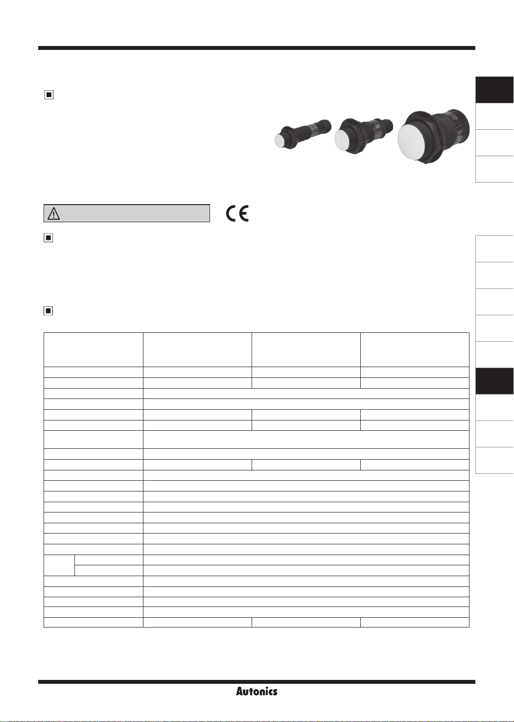
PRACM Series
Cylindrical Spatter-Resistance Connector Type Proximity Sensor
Features
● Prevent malfunction due to welding spatter with
PEFE coating
● Improved the noise immunity with dedicated IC
● Built-in reverse polarity protection circuit
(DC 3-wire type)
● Built-in surge protection circuit,
output short over current protection circuit
● IP67 protection structure (IEC standard)
● Replaceable for spatter-resistance type limit switches
Please read “Safety Considerations”
----=---------=_I C
in the instruction manual before using.
I&
E:
SENSORS
CONTROLLERS
MOTION DEVICES
SOFTWARE
The Characteristic of Spatter-Resistance Type
The hot arc from arc welding machine is adhesive even with metals or plastics.
Therefore, normal proximity sensor might have malfunction even though there are no sensing object if the arcs are put on
the sensing surface. The arcs are not adhered on the sensing part of the spatter-resistance type proximity sensor as the
part is coated with PEFE against thermal resistance.
Also, the protection cover sold optionally has the same function.
Specifications
● DC 2-wire type
PRACMT12-2DO
Model
Diameter of the sensing side 12mm 18mm 30mm
Sensing distance 2mm 5mm 10mm
Installation
Hysteresis Max. 10% of sensing distance
Standard sensing target 12×12×1mm (iron) 18×18×1mm (iron) 30×30×1mm (iron)
Setting distance 0 to 1.4mm 0 to 3.5mm 0 to 7mm
Power supply
(opera ing voltage)
Leakage current Max. 0.6mA
Response frequency
Residual voltage Max. 3.5V
Aection by Temp. Max ±10% for sensing distance at ambient temperature 20℃
Control output 2 to 100mA
Insulation resistance Over 500MΩ (at 500VDC megger)
Dielectric strength 1,500VAC 50/60Hz for 1 min
Vibration 1mm amplitude at frequency 10 to 55Hz (for 1 min) in each X, Y, Z direction for 2 hours
Shock 500m/s² (approx. 50G) in each X, Y, Z directions for 3 times
Indicator Operation indicator: Red LED
Environ-
ment
Protection circuit Surge protection circuit, output short over current protection circuit
Protection structure IP67 (IEC standards)
Material Case/Nut: PEFE coated brass, Washer: PEFE coated iron, Sensing surface: PEFE
Approval
Weight
※
sensing target, 1/2 of the sensing distance for the distance.
※
※
Ambient temperature -25 to 70℃, storage: -30 to 80
Ambient humidity 35 to 95% RH, storage: 35 to 95% RH
2
※
1: The response frequency is the average value. The standard sensing target is used and the width is set as 2 times of the standard
2: The weight includes packaging. The weight in parenthesis in for unit only.
Environment resistance is rated at no freezing or condensa ion.
1
※
PRACMT12-2DC
PRACMT12-2DO-I
PRACMT12-2DC-I
Shield (ush)
12-24VDC
(10-30VDCᜡ)
1.5kHz 500Hz 400Hz
ᜢ
Approx. 38g (approx. 26g) Approx. 61g (approx. 49g) Approx. 146g (approx. 134g)
ᜡ
PRACMT18-5DO
PRACMT18-5DC
PRACMT18-5DO-I
PRACMT18-5DC-I
℃
PRACMT30-10DO
PRACMT30-10DC
PRACMT30-10DO-I
PRACMT30-10DC-I
(A)
Photoelectric
Sensors
(B)
Fiber Optic
Sensors
(C)
LiDAR
(D)
Door/Area
Sensors
(E)
Vision
Sensors
(F)
Proximity
Sensors
(G)
Pressure
Sensors
(H)
Rotary
Encoders
(I)
Connectors/
Connector Cables/
Sensor Distribution
Boxes/ Sockets
Autonics
F-139
PRACM Series
Specifications
● DC 3-wire type
PRACM12-2DN
Model
Diameter of the sensing side 12mm 18mm 30mm
Sensing distance 2mm 5mm 10mm
Installation Shield (ush)
Hysteresis Max. 10% of sensing distance
Standard sensing target 12×12×1mm (iron) 18×18×1mm (iron) 30×30×1mm (iron)
Setting distance 0 to 1.4mm 0 to 3.5mm 0 to 7mm
Power supply
(opera ing voltage)
Current consumption Max. 10mA
Response frequency
Residual voltage Max. 1.5V
Aection by Temp. Max. ±10% for sensing distance at ambient temperature 20℃
Control output Max. 200mA
Insulation resistance Over 500MΩ (at 500VDC megger)
Dielectric strength 1,500VAC 50/60Hz for 1 min
Vibration 1mm amplitude at frequency 10 to 55Hz (for 1 min) in each X, Y, Z direction for 2 hours
Shock 500m/s² (appox. 50G) in each X, Y, Z direction for 3 times
Indicator Operation indicator: Red LED
Ambient temperature -25 to 70℃, storage: -30 to 80℃
Environ-
ment
Ambient humidity 35 to 95%RH, storage: 35 to 95%RH
Protection circuit Surge protection circuit, reverse polarity protection circuit, output short over current protection circuit
Protection structure IP67 (IEC standard)
Material Case/Nut: PEFE coated brass, Washer: PEFE coated iron, Sensing surface: PEFE
Approval
2
※
Weight
※
1: The response frequency is the average value. The standard sensing target is used and the width is set as 2 times of the standard
sensing target, 1/2 of the sensing distance for the distance.
※
2: The weight includes packaging. The weight in parenthesis in for unit only.
※
Environment resistance is rated at no freezing or condensation.
1
※
PRACM12-2DP
PRACM12-2DN2
PRACM12-2DP2
12-24VDC
(10-30VDCᜡ)
1.5kHz 500Hz 400Hz
ᜢ
Approx. 38g (approx. 26g) Approx. 61g (approx. 49g) Approx. 146g (approx. 134g)
ᜡ
PRACM18-5DN
PRACM18-5DP
PRACM18-5DN2
PRACM18-5DP2
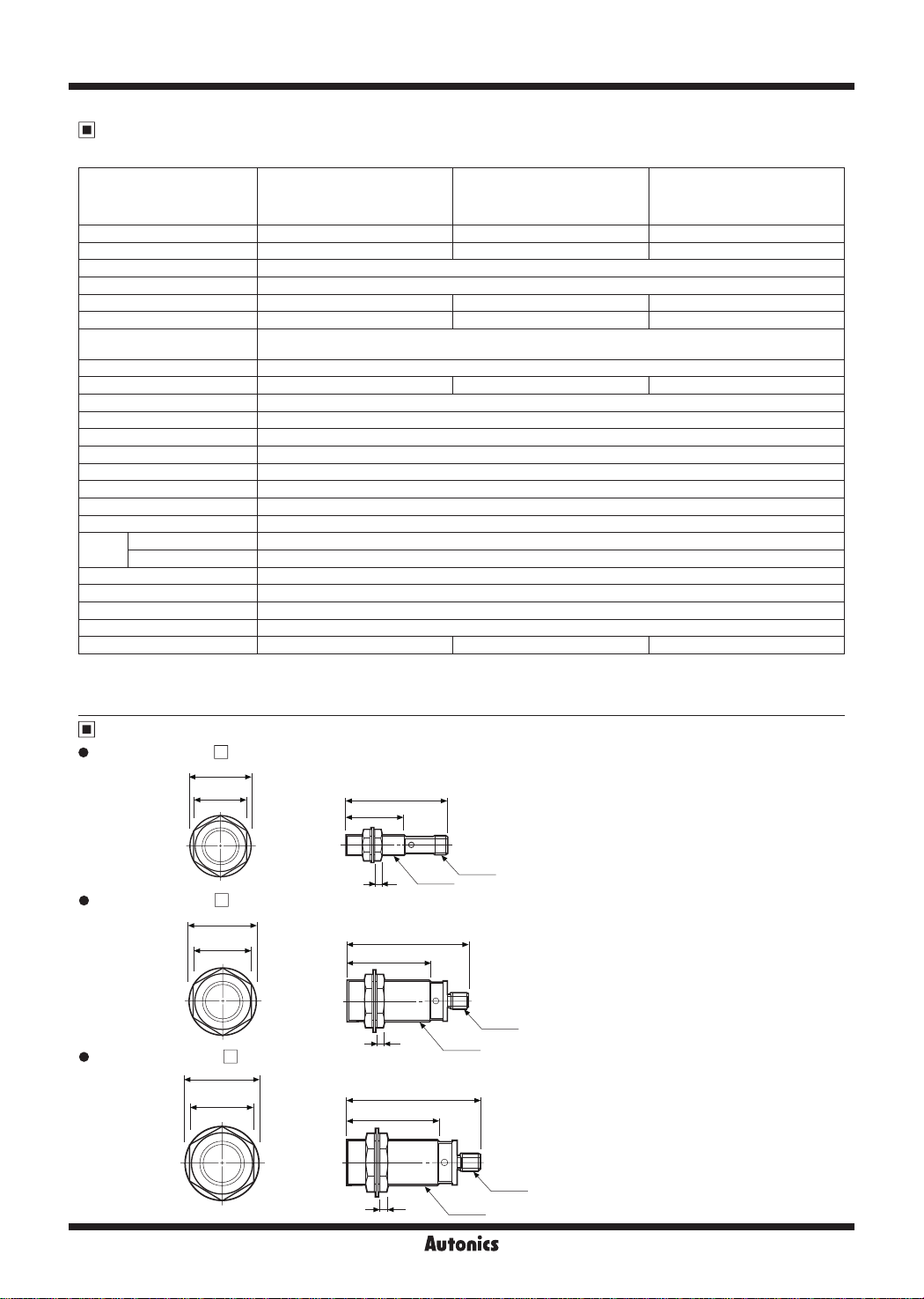
Dimensions
PRACM(T)12-2D
□
Ø21
17
56.3
32
PRACM30-10DN
PRACM30-10DP
PRACM30-10DN2
PRACM30-10DP2
(unit: mm)
PRACM(T)18-5D
•
PRACM(T)30-10D
•
F-140
~
□
Ø29
24
Ø42
35
4
~
29.5
38 5
M12×1
54.8
4
64.3
5
Autonics
M12×1
M12×1
M18×1
M12×1
M30×1

Cylindrical Spatter-Resistance Connector Type
Control Output Diagram and Load Operation
~
@
DC 2-wire type
SENSORS
Brown
4
Load
+V
Sensing
target
Load
Main circuit
Blue
3
@
DC 3-wire type
NPN output type
Brown
1
Brown
Blue
Load
Black
4
Blue
3
Load
Load
,
_____
;-----o
10kΩ
Main circuit
Wiring Diagram
~
@
DC 2-wire type (standard type)
Normally Open (N.O.) / Normally Closed (N.C )
231
4
~
※
Pin ①, ② are not used terminals.
※
For DC 3-wire type connector cable, it is available to use
Operation
Indicator
(red LED)
0V
Sensing
+V
0V
+V
0V
[
target
Load
[
(brown-black)
Output
voltage
[
(black-blue)
Operation
[
Indicator
(red LED)
231
4
~
with use black wire (12-24VDC) and blue wire (0V).
Presence
None
Operation
[
Return
ON
[
OFF
Presence
None
Operation
Return
H
L
ON
OFF
Brown
Blue
N.O.
_O__O_
_O_
_O_
N.O. N.C.
_o_
_o_
_o_
_O_
Load
Load
,
____
_r---0
N.C.
+V
0V
PNP output type
10kΩ
Main circuit
DC 2-wire type (IEC standard type)
Normally Open (N.O.) Normally Closed (N.C )
231
4
※
of N.O. type and ③,④ of N.C. type are not used
②,③
terminals.
※
The pin arrangement of connector applying IEC standard
is being developed.
※
Please attach "I" at the end of the name of standard type
for purchasing the IEC standard product.
E.g.)
PRACMT12-5DO-I
※
The connector cable for IEC standard is being developed.
Please attach "I" at the end of the name of standard type.
E.g.) CID2-2-I, CLD2-5-I
DC 3-wire type
NPN output type PNP output type
Brown
231
4
Load
Black
Blue
※
Please fasten the cleat of connector not to shown the thread. (0.39 to 0.49N.m)
※
Please fasten the vibration part with PEFE tape.
※
Formoreinformationaboutcableandspecication,
refertothe
(I) Connectors/Cable Connectors/Sensor Distr bution Boxes/Sockets
+V
0V
231
Brown
Black
4
Load
Blue
+V
0V
Brown
Blue
Brown
1
Black
4
Blue
3
Load
Load
+V
0V
+V
0V
Sensing
target
Load
(brown-black)
Output
voltage
(black-blue)
Operation
Indicator
(red LED)
231
Presence
[
None
Operation
[
Return
H
[
L
ON
[
OFF
4
Brown
Blue
N.O. N.C.
_O_
_O_
_O_
Load
+V
0V
CONTROLLERS
MOTION DEVICES
SOFTWARE
(A)
Photoelectric
Sensors
(B)
Fiber Optic
Sensors
(C)
LiDAR
(D)
Door/Area
Sensors
(E)
Vision
Sensors
(F)
Proximity
Sensors
(G)
Pressure
Sensors
(H)
Rotary
Encoders
(I)
Connectors/
Connector Cables/
Sensor Distribution
Boxes/ Sockets
Autonics
F-141

PRACM Series
Sensing Distance Feature Data by Target Material and Size
Detecting
Method
Sensing
distance (X)
target
Sensing
d
length
One side
PRACMT12-2D PRACMT18-5D
•
2.50
2.50
2.00
2.00
1L
1.50
1.50
1.00
1.00
Sensing distance X (mm)Sensing distance X (mm) Sensing distance X (mm)Sensing distance X (mm)
0.50
0.50
0.00
0.00
PRACMT30-10D
•
12.00
10.00
8.00
6.00
4.00
2.00
0.00
PRACM12-2D PRACM18-5D
•
2.50
2.50
2.00
2.00
1.50
1.50
1.00
1.00
-
1,,
I
I
~J.
:
-·1-·
8
4
4 8 10 12
10 12
V
(1
;
I•.:
~
8
4
10 12
I/
-
-
;
~.
0.50
0.50
~:
0.00
0.00
8
8
10 12
10 12
4
4
PRACM30-10D
•
12.00
□
-
-
-
.
r.
·+·
=
15 18 20 25 30 35 40 45 50 60 70 75 80 90 100
15 18 20 25 30 35 40 45 50 60 70 75 80 90 100
One side length of sensing target d (mm)
One side length of sensing target d (mm)
- -
-
T
!4,-~
-
. .
....
-
-
-
T
~
~+~
-
-
.r.
~
.
,...
□
_.,,
V
I/
-
-
-
r
r.
One side length of sensing target d (mm)
l
!;
:
!
!
:
15 18 20 25 30 35 40 45 50 60 70 75 80 90 100
□
-
-r
T_
t
-
-
-
-
15 18 20 25 30 35 40 45 50 60 70 75 80 90 100
15 18 20 25 30 35 40 45 50 60 70 75 80 90 100
One side length of sensing target d (mm)
One side length of sensing target d (mm)
□
-
-
!
:
-
-
-
• ti
!.!
~~
!.I
T
-
-
-
-
-
-
:
:
=
.r
..
.,..
.
- -
...
T
-
-
·-
-
Iron(SS401)
Stainless steel 364
(SUS364)
Brass(C3601)
Aluminum(ALS052)
Copper(C1100)
Iron(SS401)
Stainless steel 364
(SUS364)
Brass(C3601)
Aluminum(ALS052)
Copper(C1100)
Iron(SS401)
Stainless steel 364
(SUS364)
Brass(C3601)
Aluminum(ALS052)
Copper(C1100)
•
6.00
),.....
I'
~
I-
r·'"=
..
I
/V
1-
J
I
..
...
I
"i~
..
""'
'
-
-
,,.
-
:
......
..
...
:
5.00
4.00
3.00
2.00
1.00
0.00
4 8 10 12
•
6.00
5.00
4.00
3.00
2.00
Sensing distance X (mm) Sensing distance X (mm)
1.00
0.00
4 8 10 12
r-
15 18 20 25 30 35 40 45 50 60 70 75 80 90 100
One side length of sensing target d (mm)
....
-
15 18 20 25 30 35 40 45 50 60 70 75 80 90 100
One side length of sensing target d (mm)
-
:
:
-
:
□
-
:
□
---
:
T
-
-
. .
.
-
-
-
: :
- -
-
T
.,.
·-t· ·-t·
- -
..
-
-
-
.
,.
.
,.
. . . ,
TTT-·
-
-
-
-
.
,.
=
=
-
-·
-
..
:.;.
:;
-
-
-
.
=~ =~
Iron(SS401)
Stainless steel 364
(SUS364)
Brass(C3601)
-
Aluminum(ALS052)
Copper(C1100)
Iron(SS401)
Stainless steel 364
(SUS364)
Brass(C3601)
Aluminum(ALS052)
Copper(C1100)
10.00
8.00
r-t-
'jl
6.00
I
I
4.00
I•,,.•. : ...
Sensing distance X (mm) Sensing distance X (mm)
2.00
0.00
4 8 10 12
F-142
_
......
/
---t-
-t-
~~,
-..-
-~-
i-.c--t-
v,..
15 18 20 25 30 35 40 45 50 60 70 75 80 90 100
One side length of sensing target d (mm)
-----,-----r--i------1-----,-----,-,-------,-----,
..
:
..
:
Iron(SS401)
----,------,
Stainless steel 364
(SUS364)
Brass(C3601)
Aluminum(ALS052)
Copper(C1100)
Autonics

Cylindrical Spatter-Resistance Connector Type
Sensing Distance Feature Data by Parallel (Left/Right) Movement
~
Detecting
Method
Sensing
area (Y)
-
11
..
Sensing
target
tl
Sensing
distance (X)
SENSORS
CONTROLLERS
MOTION DEVICES
PRACMT12-2D
•
2.0
1.7
1.5
1.3
1.0
0.7
0.4
0.1
4.0
3.0 2.0 1.0
Left ← Center → Right
Sensing area Y (mm)
PRACM12-2D
•
2.0
1.7
□
0.0 1.0
□
2.0 3.0 4.0
PRACMT18-5D
•
5.0
4.0
3.0
2.0
1.0
10.0 8.0
PRACM18-5D PRACM30-10D
•
5.0
□
6.0 4.0 2.0 0.0 2.0 4.0 6.0 8.0 10.0
Left ← Center → Right
Sensing area Y (mm)
□
PRACMT30-10D
•
10.0
8.0
6.0
4.0
2.0
10.0 8.0
6.0 4.0 2.0 0.0 2.0 4.0 6.0 8.0 10.0
•
10.0
□
Left ← Center → Right
Sensing area Y (mm)
□
SOFTWARE
(A)
Photoelectric
Sensors
(B)
Fiber Optic
Sensors
(C)
LiDAR
(D)
Door/Area
Sensors
(E)
Vision
Sensors
(F)
Proximity
Sensors
(G)
Pressure
Sensors
(H)
Rotary
Encoders
(I)
Connectors/
Connector Cables/
Sensor Distribution
Boxes/ Sockets
1.5
1.3
1.0
Sensing distance X (mm) Sensing distance X (mm)
0.7
0.4
0.1
3.0 2.0 1.0
4.0
Left ← Center → Right
Sensing area Y (mm)
0.0 1.0
2.0 3.0 4.0
4.0
3.0
Sensing distance X (mm) Sensing distance X (mm)
2.0
1.0
10.0 8.0 6.0 4.0 2.0 0.0 2.0 4.0 6.0 8.0 10.0
Left ← Center → Right
Sensing area Y (mm)
Autonics
8.0
6.0
Sensing distance X (mm) Sensing distance X (mm)
4.0
2.0
10.0 8.0
6.0 4.0 2.0 0.0 2.0 4.0 6.0 8.0 10.0
Left ← Center → Right
Sensing area Y (mm)
F-143

PRACM Series
Proper Usage
Load connections
When using DC 2-wire type proximity sensor, the load must be connected, otherwise internal components may be
damaged. The load can be connected to either wire.
In case of the load current is small
● DC 2-wire type
Brown
+
-
Blue
< DC 2-wire type >
24VDC
Brown
' '
i
.....
Bleeder resistor (R)
Blue
Load
w.,••····:
Brown
Load
Blue
Load
< DC 2-wire type >
+
Vs
-
+
-
24VDC
If the load current is under 5mA, please make sure the
residual voltage is less than the return voltage of the load
by connecting a bleeder resistor in parallel with the load
as shown in the diagram.
V
s
R ≤
(kΩ)
I
[I: Action current of load, R: Bleeder resistance, P: Permissible power]
Mutual-interference & Influence by surrounding metals
P >
V
R
s
2
(W)
Please make the current on proximity sensor smaller than
the return current of load by connecting a bleeder resistor in
parallel.
※
W value of Bleeder resistor should be bigger for proper
heat.
V
s
R ≤
Io-Ioff
Vs: Power supply,
[
Ioff: Return current of load,
(kΩ)
Io: Min. action current of proximity sensor
P: Number of Bleeder resistance watt
P >
V
R
2
s
(W)
When several proximity sensors are mounted close to one another a malfunction of the may be caused due to mutual
interference. Therefore, be sure to keep a minimum distance between the two sensors as below chart indicates.
B
Parallel
A
Face to Face
When sensors are mounted on metallic panel, it is required to protect the sensors from being aected by any metallic
object except target. Therefore, be sure to provide a minimum distance as below chart indicates.
m
ød
ℓ
ℓ
n
ℓ
]
Model
PRACMT12-2D
Item
~
A 12 30 60
B 24 36 60
ℓ 0 0 0
Ø
d 12 18 30
m 6 15 30
n 18 27 45
PRACM12-2D
□ □ □
□ □ □
F-144
PRACMT18-5D
PRACM18-5D
Autonics
(unit: mm)
PRACMT30-10D
PRACM30-10D
 Loading...