

PMC-2HSP/PMC-2HSN Series
-|Transparent setting guide|-
2-axis High Speed Interpolation/Normal Motion Controller
▣ Features
● Independent 2-axis controlling with high operating speed of max. 4Mpps
● Linear/Circular interpolation control (PMC-2HSP)
● Realizing a wide variety of operation up to 200 steps using 17 control
commands combination (13 commands except arc/linear interpolation
command for PMC-2HSN series)
● Various control interface available (USB, RS232C, RS485, Parallel I/F)
● Controlling up to 32 axes (16-unit)
via RS485 serial communication (Modbus RTU)
● 4 operation modes: Jog, Continuous, Index, Program mode
● Symmetrical/asymmetrical trapezoid, S-shaped de/acceleration driving function
Please read “Safety Considerations”
in the instruction manual before using.
(except for PMC-2HS -485)
▣ User Manual
Please refer to user manual for detailed instructions and specications.
Visit our website (www.autonics.com) to download user manual and software [atMotion].
User manual describes installing software, setting parameter and program, operation mode, and multi-axis operation, etc.
to operate motion controller.
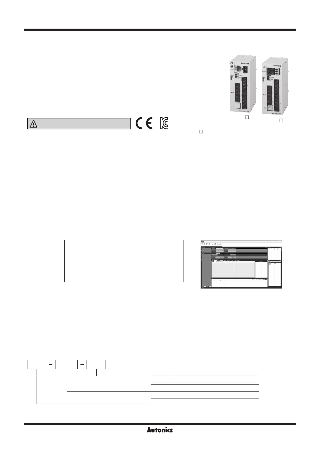
▣ Software (atMotion)
atMotion is the windows software designed to operate motion control for motion device.
Compatible with Microsoft Windows 98, NT, XP (32-bit, 64-bit), Vista (32-bit, 64-bit), 7 (32-bit, 64-bit),8 (32-bit, 64-bit)
●
and 10 (32-bit, 64-bit)
● Supports 1200, 2400, 4800, 9600, 19200, 38400, 57600, 115200 bps communication speeds
● Available to use on all OS supported COM ports (COM1 to COM256)
● Multilingual support (Korean, English)
● Provides the calculator for convenience (calculates PPS, center of interpolation, end coordinates)
Item Minimum requirements
System IBM PC compatible computer with Intel Pentium Ⅲ or above
Operations Microsoft Windows 98/NT/XP/Vista/7/8/10
Memory 256MB+
Hard disk 1GB+ of available hard disk space
VGA Resolution: 1024×768 or higher
Others RS-232 serial port (9-pin), USB port
PMC-2HS -USB
< atMotion screen > < Computer specification for using software>
PMC-2HS
-485
▣ Standard Operation Method
There are three methods to operate the motion controller.
● Operation by PC
Connect a PC and the controller with communication cable and run dedicated program (atMotion).
● Operation by Parallel I/F
Connect a sequence controller or switch to Parallel I/F.
● Operation by serial communication (dedicated communication protocol)
Using serial communication protocol, operate according to program writing by user.
▣ Ordering Information
PMC 2HSP
Axis/Type
Item
AB-10
USB
Communication type
USB USB / RS232C
485 RS485 / RS232C
2HSP 2-axis high speed interpolation
2HSN 2-axis high speed normal
PMC Programmable Motion Controller
2-axis High Speed Interpolation/Normal Motion Controller
-|Transparent setting guide|-
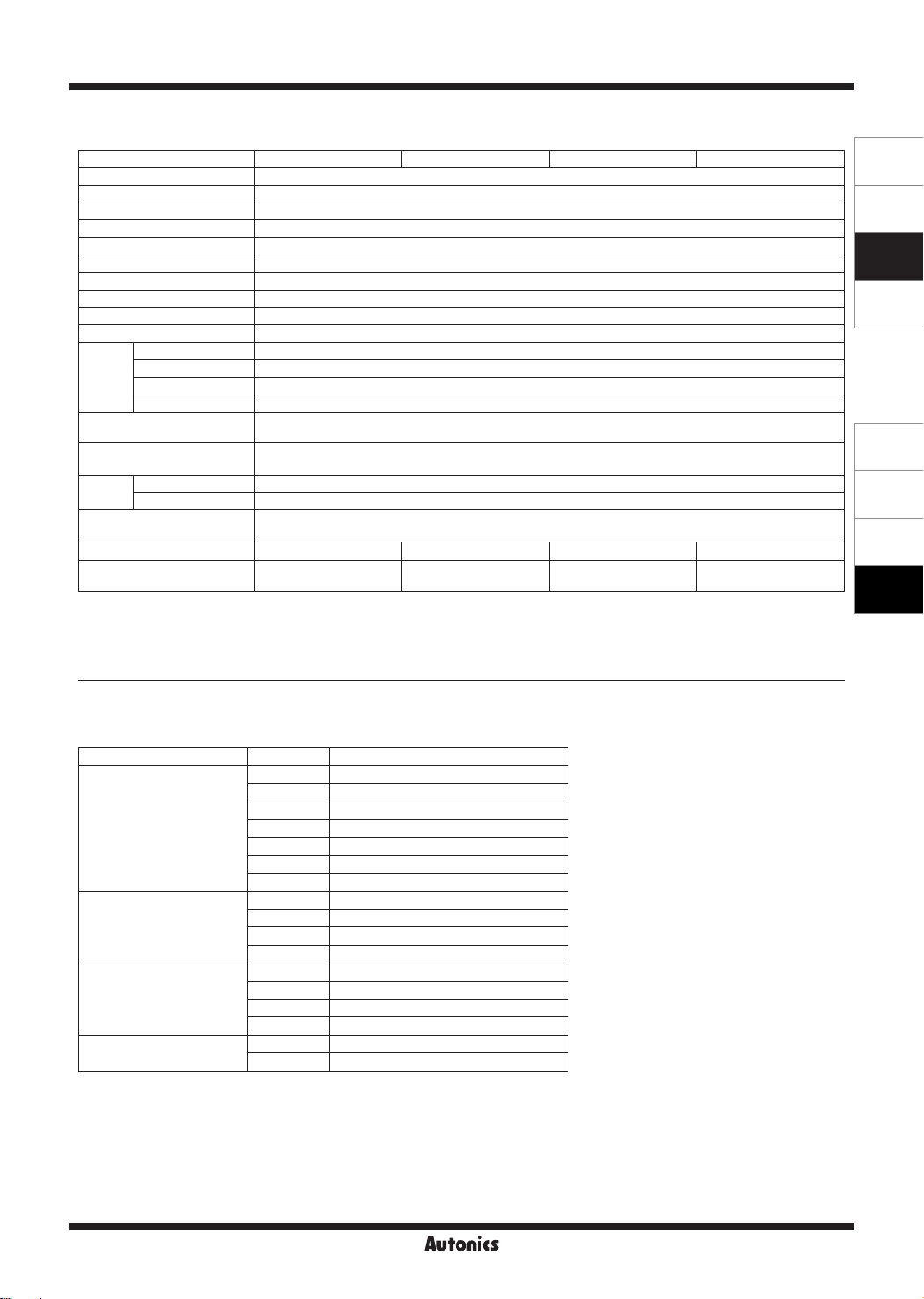
▣ Specifications
Model PMC-2HSP-USB PMC-2HSP-485 PMC-2HSN-USB PMC-2HSN-485
Control axes 2-axis
Motor for control Pulse train input stepper motor or servo motor
Power supply 24VDC
ᜡ
Allowable voltage range 90 to 110% of rated voltage
Power consumption Max. 6W
In-Position range -8,388,608 to 8,388,607 (selectable absolute/relative value, available pulse-scaling function)
Drive speed 1pps to 4Mpps (1 to 8,000pps×magnication 1 to 500)
Pulse output method 1-Pulse/2-Pulse output method (line driver output)
Operation mode Jog / Continuous / Index / Program mode
Number of index steps 64 indexes per axis
Program
function
Steps 200-step
Control command ABS, INC, HOM, LID
Start Available power On program auto start setting
※
1
, CID
※
1
, FID
1
1
※
※
, RID
, TIM, JMP, REP, RPE, ICJ, IRD, OPC, OPT, NOP, END
Home search Available power On home search setting
Home search mode
I/O
Environ
-ment
Ambient temperature 0 to 45℃, storage: -15 to 70
Ambient humidity 20 to 90%RH, storage: 20 to 90%RH
Accessory
Approval
※
2
Weight
※
These commands are only for PMC-2HSP series.
1:
※
2: The weight includes packaging. The weight in parenthesis is for unit only.
※
Environment resistance is rated at no freezing of condensation.
High speed near home search (Step 1) → Low speed near home search (Step 2) →
Encoder Z phase search (Step 3) → Oset movement (Step 4)
• Parallel I/F (CN3): 13 inputs, 4 outputs
• X-axis (CN4) / Y-axis (CN5): 8 inputs, 6 outputs (general-purpose I/O, two of each)
℃
• [Common]
Power connector, I/O connector: 3 (PI/F, X-axis, Y-axis), RS232C communication cable (1.5m): 1
• [USB type] USB communication cable 1m: 1 •[RS485 type] RS485 connector: 1
ᜢ ᜣ ᜢ ᜢ ᜣ ᜢ
Approx. 344g
(approx. 101.5g)
Approx. 308.7g
(approx. 101.6g)
Approx. 344g
(approx. 101.5g)
Approx. 308.7g
(approx. 101.6g)
SENSORS
CONTROLLERS
MOTION DEVICES
SOFTWARE
(Y)
Closed Loop
Stepper System
(Z)
Stepper Motors
(AA)
Drivers
(AB)
Motion
Controllers
▣ Program Commands
Command type Code Description
ABS Move absolute position
INC Move relative position
HOM Home search
※
Drive commands
I/O commands
Program control commands
Others
※
1: These commands are only for PMC-2HSP series.
LID
CID
FID
RID
1
※
1
※
1
※
1
2-axis linear interpolation
2-axis CW circular interpolation
2-axis CW arc interpolation
2-axis CCW arc interpolation
ICJ Jump input condition
IRD Stand-by external input
OPC ON/OFF output port
OPT ON pulse from output port
JMP Jump
REP Start repetition
RPE End repetition
END End program
TIM Timer
NOP No operation
AB-11

PMC-2HSP/PMC-2HSN Series
-|Transparent setting guide|-
▣ Connections
5-phase stepper motor
CW+
CW-
CCW+
CCW-
< Basic conguration of the motion controller (conguration only for X-axis) >
▣ Dimensions
- direction limit
sensor
5-phase micro step
motor driver
35.5
5
HOME sensor
XP+P
XP+N
XP-P
XP-N
+ direction limit
XSTOP1
PMC-2HSP/
PMC-2HSN
sensor
XLMT+XLMT-
RS232C
RS485
USB
PC
(unit: mm)
64
4
AB-12
90
97
104
connectable
35mm DIN rail

2-axis High Speed Interpolation/Normal Motion Controller
-|Transparent setting guide|-
▣ Unit Descriptions
PMC-2HS
3
2
1
-USB
4
5
PMC-2HS
3
2
1
6
-485
4
5
▣ External I/O Terminal Connection
PMC-2HS
CN2
CN1
CN3
-USB
CN6
CN4
CN5
PMC-2HS
CN2
CN1
CN3
IDS
-485
CN6
CN4
CN5
1. Power / Status indicator
Used to indicate power, communication status of the
controller, and operation status of each axis.
2. Power connector terminal
Used to connect power for controller
3. RS232C connector terminal
Used to connect RS232 serial (RJ12-DSUB9) connection cable
4. USB/RS485 connector terminal
Used to connect USB and RS485 connection cable
5. External I/O connector terminal
Used to operate various drives through input and output of
Parallel I/F, X, Y
6. ID select switch
Used to set unique ID for each node in case of RS485
communication
● Connector
Connector no. Description
CN1 Power connector
CN2 RS232C connector
CN3 Parallel I/F connector
CN4 X-axis I/O connector
CN5 Y-axis I/O connector
CN6
IDS ID selection switch
PMC-2HSP/2HSN-USB: USB connector
PMC-2HSP/2HSN-485: RS485 connector
SENSORS
CONTROLLERS
MOTION DEVICES
SOFTWARE
(Y)
Closed Loop
Stepper System
(Z)
Stepper Motors
(AA)
Drivers
(AB)
Motion
Controllers
▣ CN1: Power Connector
Pin no. Signal name
1 24VDC
2 GND (0V)
▣ CN2: RS232C Connector
Pin no. Signal name I/O Description
1 TXD Output Receiving data
2 RXD Input Transmitting data
3 GND
4
- -
- -
6
- -
※
The internal connection diagram of RS232C
communication cable is shown on the right.
-
Ground
N.C5
CN2 RS232C
connector
TXD
1
RXD
2
GND
3
4
5
6
6-wire modular
connector
< Internal connection diagram of RS232C communication cable>
Cable length 1.5m
1
6
6-wire
connector
Cable
Connector
for PC
1
2
3
4
5
6
7
8
9
DE-9S
DCD
RXD
TXD
DTR
GND
DSR
RTS
CTS
RI
AB-13

PMC-2HSP/PMC-2HSN Series
-|Transparent setting guide|-
▣ CN3: Parallel I/F Connector
The Parallel I/F connector which is connected with a sequencer or mechanical contacts operates motion controller same as
PC program. When input signal is ON, the input signal terminal and GEX terminal are connected by mechanical contacts or
open collector output and open collector output transistor is ON when the output signal is ON.
Pin no. Signal name I/O Description
1 RESET Input Reset
2 HOME Input Home search start command
3 STROBE Input Drive start command
4 X/JOG Y+ Input X-axis designate/Jog Y+
5 Y/JOG Y- Input Y-axis designate/Jog Y-
6 STEPSL0/RUN+/JOG X+ Input Register designate 0/Run+/Jog X+
7 STEPSL1/RUN-/JOG X- Input Register designate 1/Run-/Jog X-
8 STEPSL2/SPD0 Input Register designate 2/Drive speed designate 0
9 STEPSL3/SPD1 Input Register designate 3/Drive speed designate 1
10 STEPSL4/JOG Input Register designate 4/Jog designate
11 STEPSL5/STOP Input Register designate 5/Drive stop
12 MODE0 Input Operation mode designate 0
13 MODE1 Input Operation mode designate 1
14 X DRIVE/END Output X-axis drive/Drive end pulse
15 Y DRIVE/END Output Y-axis drive/Drive end pulse
16 X ERROR Output X-axis error
17 Y ERROR Output Y-axis error
18 GEX
19 GEX
20 VEX
<CN3 pin number>
20
18
16
14
12
10
8
6
4
2
19
17
15
13
11
9
7
5
3
1
◄
[Hirose connector]: HIF3BA-20PA-2.54DS
[Connector socket specication]: Contact the manufacture for the socket and cable.
Connector socket HIF3BA-20D-2.54R
I/O cable (sold separately) CO20-HP -L, CO20-HP -R Autonics
-
Ground
-
Ground
-
Power supply for sensor (24VDC, max. 100mA)
Specifications Manufacture
Hirose Electric
▣ Input/Output Connections of CN3
VEX (+24VDC)
Input
(1 to 13)
3.3k
GEX
(18, 19)
AB-14
10k
+5V
Inner
circuit
2.7k
7.2k
+24V
Output
(14 to 17)
3k
GEX
(18, 19)

2-axis High Speed Interpolation/Normal Motion Controller
-|Transparent setting guide|-
▣ CN4, CN5: X, Y-Axis Input/Output Connector
CN4 and CN5 are I/O signals for X-axis and Y-axis respectively.
The pin arrangement of CN4 and CN5 are equal. 'n' in the table means X for CN4 and Y for CN5.
Pin no. Signal name I/O Description
1 n P+P Output Drive pulse in the CW + direction
2 n P+N Output Drive pulse in the CW - direction
3 n P-P Output Drive pulse in the CCW + direction
4 n P-N Output Drive pulse in the CCW - direction
5 n OUT0 Output General output 0
6 n OUT1 Output General output 1
7 n IN0 Input General input 0
8 n IN1 Input General input 1
<CN4, CN5 pin no.>
►
1
2
4
3
6
5
8
7
10
9
12
11
14
13
16
15
9 n STOP2 Input Encoder Z-phase
10 n STOP1 Input Home
11 n STOP0 Input Near Home
12 n LMT+ Input + direction limit
13 n LMT- Input - direction limit
[Hirose connector]: HIF3BA-16PA-2.54DS
[Connector socket specication]: Contact the manufacture for
the socket and cable.
Specifications Manufacture
Connector socket HIF3BA-16D-2.54R
14 EMG Input Emergency stop
15 GEX
16 VEX
※
CN4, 5 input/output is same as CN3 input/output connections.
-
Ground
Power supply for sensor
-
(24VDC, max. 100mA)
Drive pulse output of motion controller which is inputted to motor driver is line driver output.
Hirose Electric
SENSORS
CONTROLLERS
MOTION DEVICES
SOFTWARE
(Y)
Closed Loop
Stepper System
(Z)
Stepper Motors
(AA)
Drivers
(AB)
Motion
Controllers
E.g. Connection with a motor driver
E.g. Connect of Limit and Home signal
CN4, CN5 Motor driver
1 CW+
n P+P
2
n P+N
3 CCW+
n P-P
4
n P-N
CW-
CCW-
VEX (+24V)
▣ CN6: RS485 Connector
Pin no. Signal name I/O Description
1 B (-) I/O Transmitting / Receiving data
2 A (+) I/O Transmitting / Receiving data
※
3 G
※
1: Connect the ground when it is required depending on communication environments.
-
1
CN4, CN5
n LMT+
n LMT-
n STOP1
GEX
16
+ direction limit switch
12
13
- direction limit switch
Home sensor
10
15
G
A
B
AB-15
 Loading...