

SENSORS
CONTROLLERS
MOTION DEVICES
SOFTWARE
(Y)
Closed Loop
Stepper System
(Z)
Stepper Motors
(AA)
Drivers
(AB)
Motion
Controllers
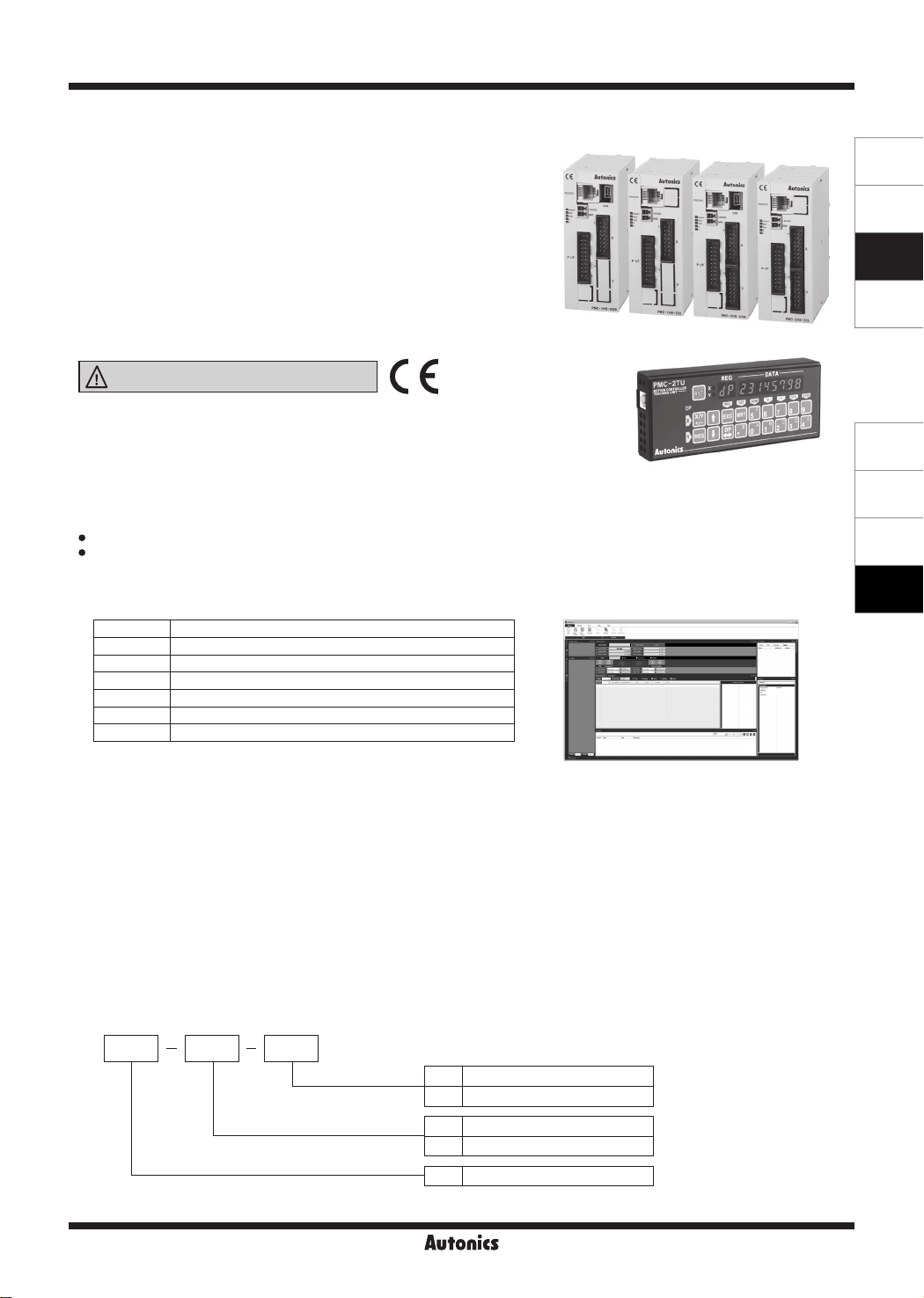
PMC-1HS/PMC-2HS Series
1·2-Axis High Speed Programmable Motion Controller
▣ Features
● Max. 4Mpps high-speed operation
● 4 operation modes: Jog, Continuous, Index, Program mode
● 12 control command and 64 steps of operations
● Parallel I/O terminal built in which is connectable on PLC
● Create and edit operating programs, parameters by
dedicated software
● Easy to operation of X, Y stage with joy stick
● RS232C port for all types
● Teaching and monitoring function by using teaching unit
(PMC-2TU-232, sold separately)
Please read “Safety Considerations”
in the instruction manual before using.
▣ Manual
For the detail information and instructions, please refer to user manual and
be sure to follow cautions written in the technical descriptions
▣ Software (atMotion)
atMotion is a comprehensive motion device management program that can be used with Autonics motion controllers.
•
atMotion provides GUI control for easy and convenient parameter setting and monitoring data management of multiple devices.
•
PMC-1HS
(USB)
PMC-1HS
(232)
PMC-2HS
(USB)
PMC-2TU-232,
sold separately
PMC-2HS
(232)
< Computer specification for using software>
Item Minimum requirements
System IBM PC compatible computer with Intel Pentium Ⅲ or above
Operations Microsoft Windows 98/NT/XP/Vista/7/8/10
Memory 256MB+
Hard disk 1GB+ of available hard disk space
VGA Resolution: 1024×768 or higher
Others RS-232 serial port (9-pin), USB port
< atMotion screen >
▣ Standard Operation Method
There are four methods to operate PMC-1HS/PMC-2HS.
● Start with PC
Connect a PC and the motion controller body via a communication cable, starts the operation program.
● Start with Parallel I/F
Connect a sequence controller or switch to the Parallel I/F.
● Start with teaching unit (PMC-2TU-232, sold separately)
Connect a communication cable annexed to a teaching unit (PMC-2TU-232).
It is available to execute Jog output, home output and programs by drive operation of teaching unit.
● Control by serial communication
The PMC-1HS/2HS Series provides serial communication commands.
The PMC-1HS/2HS is connected to a PC or a sequence controller via an USB cable or RS-232C communication cable and it can control
axes by means of user's independent program.
▣ Ordering Information
PMC 2HS
Axis/Type
Item
-I
USB
I
Communication type
232 RS232C
USB USB, RS232C multiple use
I I
1HS 1-axis high speed stand-alone
2HS 2-axis high speed stand-alone
PMC Programmable Motion Controller
Autonics
AB-3
PMC-1HS/PMC-2HS Series
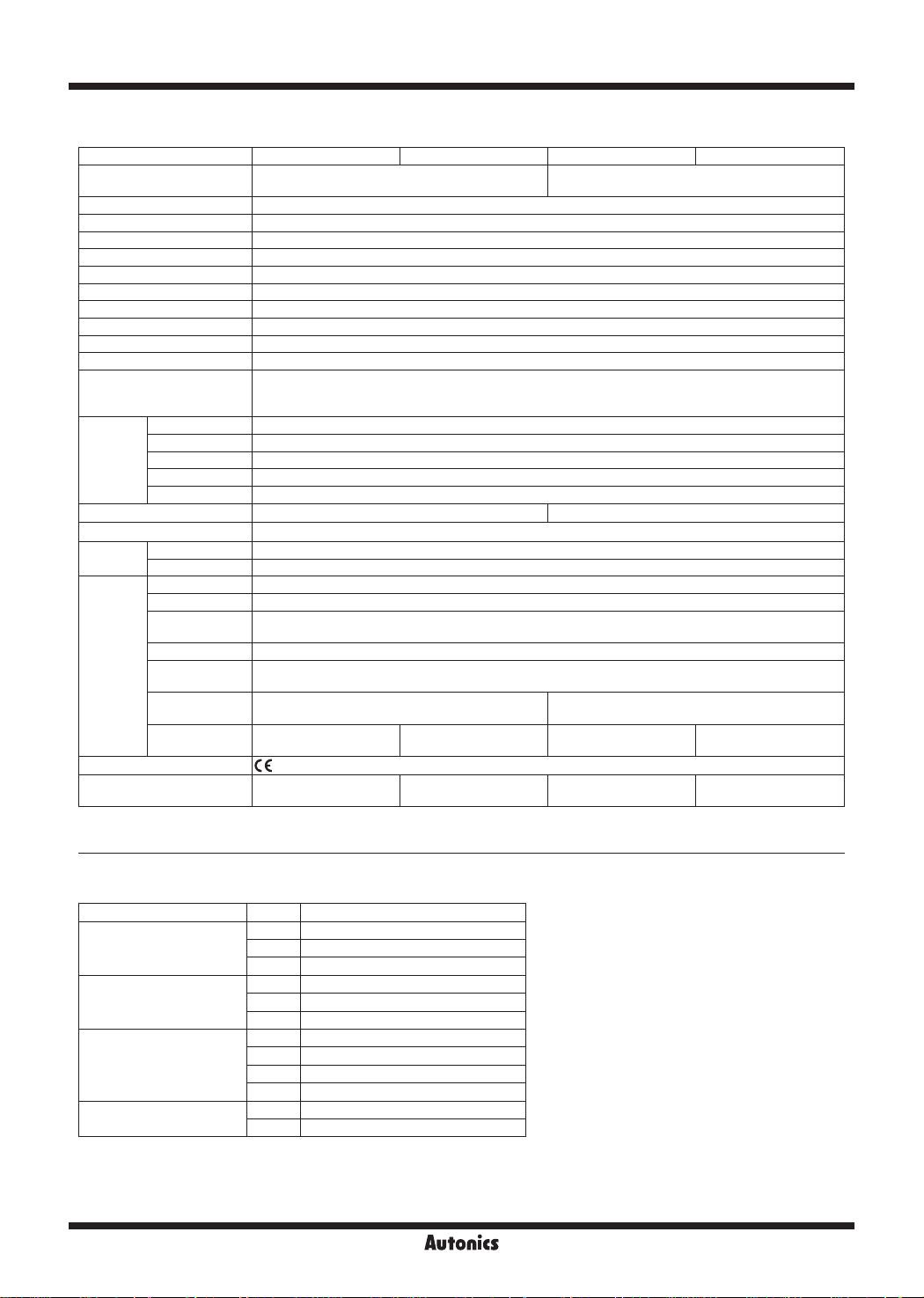
▣ Specifications
Model PMC-1HS-232 PMC-1HS-USB PMC-2HS-232 PMC-2HS-USB
Control axes 1-axis
Motor for control Pulse train input stepper motor or servo motor
Power supply 24VDCᜡ ±10%
Power consump ion Max. 6W
Operation mode Jog / Continuous / Index / Program mode
In-Position setting ABSOLUTE / INCREMENTAL method
Number of index steps 64 indexes per axis
In-Position range -8,388,608 to +8,388,607 (supports pulse scaling function)
Number of drive speed 4
Drive Speed 1pps to 4Mpps (1 to 8,000×magnication 1 to 500)
Pulse output method 2-pulse output method (line driver output)
Home search mode
Save EEPROM
Program
function
General output 1-point 2-point
Control interface Parallel I/F
Environment
Accessory
Approval
Weight
1: The weight includes packing. The weight in parenthesis is for unit only.
※
※
Environment resistance is rated at no freezing of condensation.
Steps 64-step
Control command ABS, INC, HOM, IJP, OUT, OTP, JMP, REP, RPE, END, TIM, NOP (12 types)
Start Available power ON program auto start setting
Home search Available power ON home search setting
Ambient temp. 0 to 45℃
Ambient humidity 35 to 85%RH
Common User manual, CD
Power connector [CN1] MC1, 5/2-ST-3.5 (PHOENIX): 1
RS-232C
connector
P I/F connector [CN3] 20P MIL standard, 2.54mm connector: 1
X-axis I/O
connector
Y-axis I/O
connector
USB connector
1
※
High speed near home search (Step 1) → Low speed near home search (Step 2)
→ Encoder Z-phase search (Step 3) → Oset movement (Step 4).
Conguring the detection direction and Enable/Disable in each step.
[CN2] RS-232C communication cable (1.5m): 1
[CN4] 16P MIL standard, 2.54mm connector: 1 (In case of 2HS, using 2)
-
-
CE:
Approx. 386g
(approx. 96.8g)
I I
2-axis
(Each axis can be independently programmed)
[CN5] 16P MIL standard, 2.54mm connector: 1
USB communication
cable (1m): 1
I I
Approx. 421.6g
(approx. 96.9g)
I I
-
Approx. 393.6g
(approx. 100.2g)
USB communication
cable (1m): 1
Approx. 432.2g
(approx. 100.4g)
▣ Program Commands
Command type Code Description
ABS Move absolute position
Drive commands
I/O commands
Program control commands
Others
AB-4
INC Move relative position
HOM Home search
IJP Jump input condition
OUT ON/OFF of output port
OTP ON pulse from output port (certain time)
JMP Jump
REP Start repetition
RPE End repetition
END End program
TIM Timer
NOP No operation
SENSORS
CONTROLLERS
MOTION DEVICES
SOFTWARE
(Y)
Closed Loop
Stepper System
(Z)
Stepper Motors
(AA)
Drivers
(AB)
Motion
Controllers
1·2-Axis High Speed Programmable Motion Controller
▣ Connections
5-phase stepper motor
+ direction
limit sensor
XLMT+XLMT- XSTOP1
RS232C
USB
PC
64
(unit: mm)
5-phase micro step
CW+
CW-
CCW+
CCW-
< Basic conguration of the motion controller (conguration only for X-axis) >
▣ Dimensions
35.5
5
- direction
limit sensor
motor driver
HOME sensor
XP+P
XP+N
XP-P
XP-N
PMC-1HS/
PMC-2HS
4
=
90
97
104
connectable
35mm DIN rail
Sold separately (teaching unit, PMC-2TU-232)
PMC-2TU
MOTION CONTROLLER
TEACHING
UNIT-
REG
[RsTJ~g
~~
□[
(el
[I] E]
CeJ
~
(el
CD
~
r;:J
DATA
8
EJ
CeJ
[;:]
~Bw~~~~[i::J~~
Autonics
150
Autonics
I
~
r;:J
=
I.
00
gg
00
ee
00
00
00
00
00
23
,-
,_
.I
61.7
AB-5

PMC-1HS/PMC-2HS Series
▣ Unit Descriptions
3
2
1
4
Used to indicate power, communication status of the
controller, and operation status of each axis.
2. Power connector terminal
Used to connect power for controller
3. RS232C connector terminal
1. Power / Status indicator
5
Used to connect RS232 serial (RJ12-DSUB9) connection cable
4. USB/RS485 connector terminal
Used to connect USB and RS485 connection cable
5. External I/O connector terminal
Used to operate various drives through input and output of
Parallel I/F, X, Y
▣ External I/O Terminal Connection
CN2
CN1
CN3
CN6
CN4
CN5
Connector No. Description
CN1 Power connector
CN2 RS232C connector (connect with PMC-2TU-232)
CN3 Parallel I/F connector
CN4 X-axis I/O connector
CN5 Y-axis I/O connector
CN6 USB connector
※
PMC-1HS-232 does not have CN5 and CN6,
PMC-1HS-USB does not have CN5, and
PMC-2HS-232 does not have CN6.
▣ CN1: Power Connector
Pin No. Signal name
1 24VDC
2 GND (0V)
▣ CN2: RS232C Connector
Pin No. Signal name Input/Output Description
1 TXD Output Transmitting data
2 RXD Input Receiving data
3 GND
- -
4
- -
6
- -
The internal connection diagram of RS232C
※
-
communication cable is as shown below.
AB-6
Ground
N.C5
CN2 RS232C connector
1
TXD
2
RXD
GND
3
4
5
6
6P modular
connector
< Internal connection diagram of RS232C communication cable>
Cable length 1.5m
1
6
6P connector Cable
PC connection connector
Autonics
1
2
3
4
5
6
7
8
9
DE-9S
DCD
RXD
TXD
DTR
GND
DSR
RTS
CTS
RI

SENSORS
CONTROLLERS
MOTION DEVICES
SOFTWARE
(Y)
Closed Loop
Stepper System
(Z)
Stepper Motors
(AA)
Drivers
(AB)
Motion
Controllers
1·2-Axis High Speed Programmable Motion Controller
▣ CN3: Parallel I/F Connector
Motion controller is controlled via Parallel I/F connected with a sequencer or mechanical junction as the dedicated program.
'The input signal is in the ON state' means that the input signal and GEX terminal is connected via a mechanical junction or an open collector.
'The output is in the ON state' means that an open collector output transistor becomes high.
Pin No. Signal name Input/Output Description
1 RESET Input Reset
2 HOME Input Home search start
3 STROBE Input Drive start
4 X/JOG Y+ Input X-axis setting/Jog 2 mode Y+
5 Y/JOG Y- Input Y-axis setting/Jog 2 mode Y-
6 REGSL0/RUN+/JOG X+ Input Register setting 0/Run+/Jog 2 mode X+
7 REGSL1/RUN-/JOG X- Input Register setting 1/Run-/Jog 2 mode X-
8 REGSL2/SPD0 Input Register setting 2/Drive speed setting 0
9 REGSL3/SPD1 Input Register setting 3/Drive speed setting 1
10 REGSL4/JOG Input Register setting 4/Jog setting
11 REGSL5/STOP Input Register setting 5/Drive stop
12 MODE0 Input Operation mode setting 0
13 MODE1 Input Operation mode setting 1
14 X DRIVE/END Output X-axis drive/Drive end pulse
15 Y DRIVE/END Output Y-axis drive/Drive end pulse
16 X ERROR Output X-axis error
17 Y ERROR Output Y-axis error
18 GEX 0V GND
19 GEX 0V GND
20 VEX +24V Power output for sensor (less than 24VDC, 100mA)
<CN3 pin number>
20 19
■■
17
18
■■
15
16
■■
14
■■
12
■■
10
■■
8
■■
6
■■
4
■■
2
■■
▣ Input/Output Connections of CN3
[Hirose connector]: HIF3BA-20PA-2.54DS
[Connector socket specication]: Contact the manufacture for the socket and cable.
13
11
Connector socket H F3BA-20D-2 54R
9
/O cable (sold separately) CO20-HP -L, CO20-HP -R Autonics
7
Specifications Manufacture
Hirose Electric
□ □
5
3
1
◄
VEX (+24VDC)
+5V
2.7k
Inner circuit
Input
(1 to 13)
3.3k
10k
Inner
circuit
GEX
(18, 19)
< CN3 control input connections > < CN3 control output connections >
7.2k
+24V
Output
(14 to 17)
3k
GEX
(18, 19)
Autonics
AB-7

PMC-1HS/PMC-2HS Series
▣ CN4, CN5: X, Y-Axis Input/Output Connector
CN4 and CN5 are the I/O signal connector for X-axis and Y-axis respectively.
The pin arrangement of CN4 and CN5 are equal. PMC-1HS does not have CN5.
'n' in the below table means X for CN4 and Y for CN5.
Pin No. Signal name Input/Output Description
1 nP+P Output CW +direction drive pulse
2 nP+N Output CW -direction drive pulse
3 nP-P Output CCW +direction drive pulse
4 nP-N Output CCW -direction drive pulse
5 n OUT0 Output General output 0/DCC
6 n INPOS Input Servo In-Position complete
7 n ALARM Input Servo alarm
8 GEX 0V GND
9 n STOP2 Input Encoder Z-phase
10 n STOP1 Input Home
11 n STOP0 Input Near Home
12 n LMT+ Input LMT+
13 n LMT- Input LMT-
14 EMG Input Emergency stop
15 GEX 0V GND
16 VEX +24V Power output for sensor (less than 24VDC, 100mA)
※
CN4, 5 input/output circuit except drive pulse is same as CN3 input/output circuit.
Drive pulse output of motion controller which input by motor driver is line driver output.
<CN4, CN5 pin number>
►
1 2
■■
4
3
■■
6
5
7
9
11
13
15
■■
■■
■■
■■
■■
■■
[Hirose connector]: HIF3BA-16PA-2 54DS
[Connector socket specica ion]: Contact he manufacture for the socket and cable.
8
10
Connector socket HIF3BA-16D-2.54R
12
14
16
Specifications Manufacture
Hirose Electric
E.g. Connection with a motor driver
CN4, CN5 Motor driver
1
nP+P
2
nP+N
3
nP-P
4
nP-N
AB-8
E.g. Connect of Limit and Home signal
CN4, CN5
nLMT+
nLMT-
GEX
16
12
13
10
15
VEX (+24V)
nSTOP1
Autonics
+ direction limit
- direction limit
Home

SENSORS
CONTROLLERS
MOTION DEVICES
SOFTWARE
(Y)
Closed Loop
Stepper System
(Z)
Stepper Motors
(AA)
Drivers
(AB)
Motion
Controllers
1·2-Axis High Speed Programmable Motion Controller
▣ Teaching Unit PMC-2TU-232 (sold separately)
The teaching unit (PMC-2TU-232) is a device that builds the operation mode parameter and operation program for the
main body without a PC. In addition, it can carry out the start of the operation program, the home search and Jog operation.
The teaching unit is used by connection the private cable (1.5m) to the RS-232C connector (CN2) of the main body.
- J
PMC-2TU-232
connection cable (accessory)
Teaching unit consists of data edit mode and drive operation mode.
The data edit mode displays a register number to the REG of the display part, and the drive handling mode displays dp (drive operation).
When turned on, it starts as the drive handling mode (dp display).
The [DP] button is used to convert the status of the data edit mode and the drive operation mode.
Mode Operation REG display
Data edit
Drive handling
The front panel of the teaching unit is as shown below;
2 3
1
• Adding operation mode parameter and operation program
• Index drive operation
• Displaying the current posi ion
• Jog operation
• Home search
• Program execu ion
I • •
Register number
DP
(drive operation)
4
... .. .
1. Reset:
2. X/Y display:
3. Register number display/dp
4. Data display
5. Input button
6. Button display for drive operation
____
6
Reset the controller and teaching unit.
Display the currently selected axis.
:
Displays the currently selected register number when data is editing and dp when operating drive.
:
Displays the data of each register when data is editing and the current position of the selected axis when operating
drive.
• X/Y: Converts the selecting axis. It is used to convert the sign of an input value when the value is entered and a mode
data that the mode data is entered.
• REG:
It is used to input the register number to display.
If this button is pressed on the data input, the data input is canceled and returns to the state before the data input.
• ↑↓: Increases / decreases the displayed register number.
• EXC: Runs the displayed command. However, this command is only valid for ABS, INC, OUT, OTP and HOM 1 to 4
commands.
• DP: Converts the drive handling status and the data edit status.
• WRT: Adds a value when data is editing.
:
Displays button function as yellow letters to the left or the top of the input button in drive handling status.
The top end and the bottom end of the button handle X-axis and Y-axis respectively.
!.
..
xn
8tJ
D i i i
1
!v m D
..........................................................................................
~
!I
Ii
■
Iii
"
.
.....
Ii
II
.. !!
Ii
i
.. ·
5
Autonics
AB-9
 Loading...