

Page 1
-|Transparent setting guide|-
MT4Y/MT4W Series
DIN W72×H36mm, W96×H48mm, Digital Multi Panel Meter
▣ Features
● Various input/output (default: indicator)
- Input: DC voltage, DC current, AC voltage, AC current
- Output: RS485 communication output, Low speed serial output,
transmission (DC4-20mA) output, BCD dynamic output,
NPN/PNP open collector output, relay output
● Maximum allowed input
: 500VDC, 500VAC, DC5A, AC5A
● Display range: -1999 to 9999
● High/low-limit display scale function
● AC frequency measurement (range: 0.1 to 9999Hz)
● Various functions: Monitoring peak display value function,
display cycle delay function, zero adjustment function,
high display correction function, transmission (DC4-20mA) output
scale function etc.
● Power supply: 12-24VDC, 100-240VAC 50/60Hz
Please read “Safety Considerations”
in the instruction manual before using.
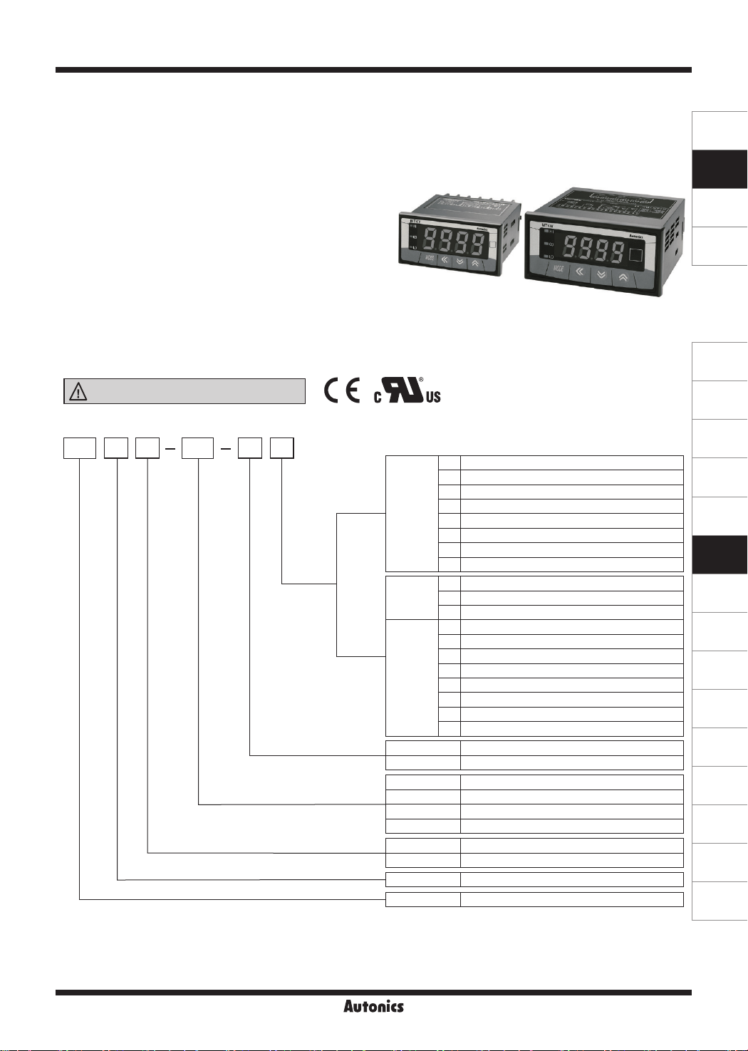
▣ Ordering Information
MT DV
4 4 NW
MT4Y
Output
MT4W
Power supply
Measurement function (input)
Size
Digit
Item
※
MT4Y-☐-43 (relay (low out)+transmission (DC4-20mA) output) models.
※
※
lST
1: Only
2:
(preset output mode) setting is available in MT4Y-☐-43 (relay (low out)+transmission (DC4-20mA) output) and
※
Only for MT4W.
To measure the current over DC5A, please select DV type because the shunt should be used.
In case of selecting frequency display, no output will be provided even if it is output support models.
(main output, sub output and RS485 communication output)
100-240VAC
12-24VDC,
100-240VAC
100-240VAC
※
1
4 100-240VAC 50/60Hz
DV DC voltage
DA DC current
AV AC voltage
AA AC current
Y DIN W72×H36mm
W DIN W96×H48mm
4 9999 (4-digit)
MT Multi meter
N
Indicator
0
Relay output
1
NPN open collector output
2
PNP open collector output
※
1
3
Relay (low out)+transmission (DC4-20mA) output
※
1
4
Relay (low out)+RS485 communication output
5
BCD dynamic output
6
Low speed serial output
N
Indicator
0
Relay+transmission (DC4-20mA) output
1
Relay output
2
NPN open collector+BCD dynamic output
3
PNP open collector+BCD dynamic output
4
NPN open collector+transmission (DC4-20mA) output
5
PNP open collector+transmission (DC4-20mA) output
6
NPN open collector+low speed serial output
7
PNP open collector+low speed serial output
8
NPN open collector+RS485 communication output
9
PNP open collector+RS485 communication output
2
12-24VDC
SENSORS
CONTROLLERS
MOTION DEVICES
SOFTWARE
(J)
Temperature
Controllers
(K)
SSRs
(L)
Power
Controllers
(M)
Counters
(N)
Timers
(O)
Digital
Panel Meters
(P)
Indicators
(Q)
Converters
(R)
Digital
Display Units
(S)
Sensor
Controllers
(T)
Switching
Mode Power
Supplies
(U)
Recorders
(V)
HMIs
(W)
Panel PC
(X)
Field Network
Devices
O-25
Page 2
MT4Y/MT4W Series
-|Transparent setting guide|-
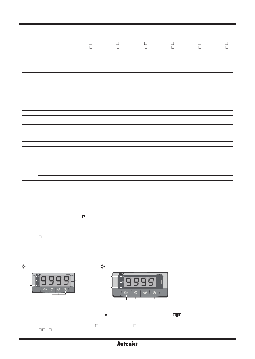
▣ Specifications
Series
Measurement input
Power supply 100-240VACᜠ 50/60Hz 12-24VDC
Allowable voltage range 90 to 110% 90 to 110%
Power consumption 5VA 5W
Display method 7-segment LED display (red) (character height: 14.2mm)
Display accuracy
Max. allowable input 110% F.S. for each measured input range
A/D conversion method ΣΔ (Sigma Delta) ADC
Sampling cycle DC input: 50ms, AC input: 16.6ms
Max. display range -1999 to 9999 (4-digit)
Preset output
Sub output
(transmission output)
AC measurement
Frequency measurement
Hold function
Insulation resistance Over 100MΩ (at 500VDC megger, between external terminal and case)
Dielectric strength 2000VAC 50/60Hz for 1 min (between external terminal and case)
Noise immunity ±2kV the square wave noise (pulse width: 1㎲) by the noise simulator
Vibration
Shock
Relay
life cycle
Environ
-ment
Insulation type
Approval
※3
Weight
※
1: AC, frequency measurement functions are only for AC measurement input type.
※
2: MT4Y-
※
3: The weight includes packaging. The weight in parenthesis is for unit only.
※
Environment resistance is rated at no freezing or condensation.
※1
※2
Mechanical 0.75mm amplitude at frequency of 10 to 55Hz (for 1 min) in each X, Y, Z direction for 2 hours
Malfunction 0.5mm amplitude at frequency of 10 to 55Hz (for 1 min) in each X, Y, Z direction for 10 min
Mechanical 100m/s² (approx. 10G) in each X, Y, Z direction for 3 times
Malfunction 300m/s² (approx. 30G) in each X, Y, Z direction for 3 times
Malfunction Min. 20,000,000 operations
Mechanical Min. 100,000 operations (250VAC 3A load current)
Ambient temperature -10 to 50℃, storage: -20 to 60
Ambient humidity 35 to 85%RH, storage: 35 to 85%RH
-4N model has no hold function.
MT4Y-DV-4
MT4Y-DA-4
DC voltage,
current
• 23℃±5
• -10℃ to 50
• Relay output - Contact capacity: 250VACᜠ 3A, 30VDCᜡ 3A / Contact composition: N.O (1a)
• NPN/PNP open collector output - Max. 12-24VDCᜡ ±2V 50mA (resistive load)
• RS485 comm output - Baud rate: 1,200/2,400/4,800/9,600, Communication method: 2-wire half duplex,
• Serial/BCD dynamic output - NPN open collector output: Max. 12-24VDCᜡ 50mA (resistive load)
• DC4-20mA output Selectable RMS or AVG
※1
Measurement range: 0.100 to 9999Hz (variable by decimal point position)
Includes (external hold function)
Double insulation or reinforced insulation
(mark:
ᜢ ᜧ ᜢ
Approx. 213.5g (approx. 134g) Approx. 326g (approx. 211g)
MT4Y-AV-4
MT4Y-AA-4
AC voltage,
current,
frequency
DC input: F.S. ±0.1% rdg±2-digit / AC input: F.S. ±0.3% rdg±3-digit (frequency: F.S.±0.1% rdg±2-digit)
℃ -
※
For 5A terminal of current Input,
DC/AC
℃ -
, dielectric strength between the measurement input part and the power part: 1kV)
input
Synchronous method: Asynchronous method, Protocol: Modbus type
Resolution: 12,000 division (load resistance max. 600Ω), Response time: max. 450ms
MT4W-DV-4
MT4W-DA-4
DC voltage,
current
F.S +0.3% rdg ±3-digit
: F.S.±0.5% rdg±3-digit
℃
MT4W-AV-4
MT4W-AA-4
AC voltage,
current,
frequency
MT4W-DV-1
MT4W-DA-1
DC voltage,
current
MT4W-AV-1
MT4W-AA-1
AC voltage,
current,
frequency
ᜡ
▣ Unit Description
MT4Y Series MT4W Series
1
2
3
5
4
1. HI: High output indication of preset
2. GO: GO output indication of preset
3. LO: Low output indication of preset
※
There is no 1, 2, 3 on a display panel of MT4Y-
※
In MT4Y- - 3, 4, OUT is used for Go output display and there is no 1, 3 in display panel.
6
O-26
1
2
3
4
MODE
key: mode key
4.
5.
key: moves digit, enters parameter mode, key: changes sv
6. unit label part
-4N, 45, 46 and MT4W- -4N.
5
6
Page 3
-|Transparent setting guide|-
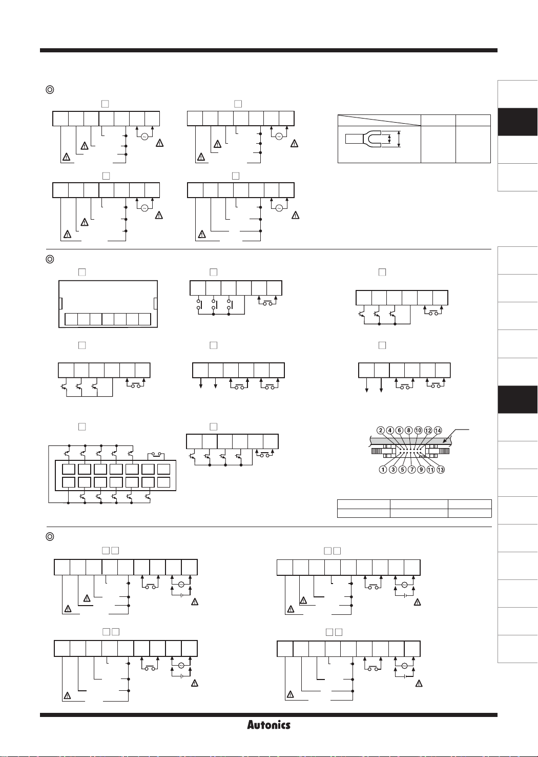
▣ Connections
Measurement input terminal connection of MT4Y Series
● MT4Y-DV-4
1 2 3 4 5 6 7
250mV
/50mV
5V/1V
50V/10V
500V/100V
SOURCE
100-240VAC
50/60Hz 5VA
● MT4Y-DA-4
1 2 3 4 5 6 7
5mA
/2mA
50mA/
4-20mA
500mA/200mA
5A/2A
SOURCE
100-240VAC
50/60Hz 5VA
Output terminal connection of MT4Y Series
●MT4Y- -4N
1 2 3 4 5 6 7
●MT4Y- -42
(triple PNP open collector output)
8 9 10 11 12 13
HI GO LO COM
●MT4Y- -45
(BCD dynamic output)
A C D0 D2 Dot
2 4 6 8 10 12 14
1 3 5 7 9 11 13
COM POLB D D1 D3
(indicator)
Hold/Zero
Hold/Zero
Measurement input terminal connection of MT4W Series
● MT4W-DV-
1 2 3 4 5 6 7 8 9
250mV
/50mV
5V/1V
50V/10V
500V/100V
● MT4W-DA-
1 2 3 4 5 6 7 8 9
50mA/
4-20mA
500mA/200mA
5A/2A
5mA
/2mA
Hold/Zero
COM
Hold/Zero
COM
● MT4Y-AV-4
1 2 3 4 5 6 7
2V/1V
20V/10V
110V/50V
500V/250V
SOURCE
100-240VAC
50/60Hz 5VA
● MT4Y-AA-4
1 2 3 4 5 6 7
100mA
/50mA
SOURCE
100-240VAC
50/60Hz 5VA
5A/2.5A
●MT4Y- -40
500mA
/250mA
1A
(triple relay output)
8 9 10 11 12 13
HI GO LO COM
CONTACT OUT
: 250VAC 3A 1a, 30VDC 3A 1a RESISTIVE LOAD
Hold/Zero
●MT4Y- -43
(relay+transmission (DC4-20mA) output)
8 9 10 11 12 13
+ -
DC4-20mALoad
600Ω max.
●MT4Y- -46
Hold/Zero
OUT1
CONTACT OUT
: 250VAC 3A 1a, 30VDC 3A 1a
RESISTIVE LOAD
(low speed serial output)
8 9 10 11 12 13
Hold/Zero
CLOCK DATA LATCH POL
※
POL: When a display value is "-",
COM
the signal of "-" will be outputted.
● MT4W-AV-
1 2 3 4 5 6 7 8 9
+ -
SOURCE
12-24VDC 5W
100-240VAC
50/60Hz 5VA
● MT4W-AA-
1 2 3 4 5 6 7 8 9
+ -
SOURCE
12-24VDC 5W
100-240VAC
50/60Hz 5VA
110V/50V
500V/250V
5A/2.5A
Multi Panel Meter
※
Use terminals of size specied below.
※
Use the Copper-conductor wire with the
temperature class 60.
a b
a b
<Forked>
●MT4Y- -41
(triple NPN open collector output)
8 9 10 11 12 13
HI GO LO COM
●MT4Y- -44
(relay+RS485 communication output)
8 9 10 11 12 13
B (-) A (+)
RS485
※
Hirose connector: HIF3BA-14PA-2.54DS
※
Connector socket specification: Contact the
manufacture for the socket and cable.
Hold/Zero
Hold/Zero
Specifications
SOURCE
12-24VDC
100-240VAC
50/60Hz 5VA
SOURCE
12-24VDC
100-240VAC
50/60Hz 5VA
Connector socket HIF3BA-14D-2.54R Hirose Electric
2V/1V
20V/10V
COM
100mA
/50mA
500mA
/250mA
1A
COM
Min.
3.5mm
Hold/Zero
Hold/Zero
OUT1
CONTACT OUT
: 250VAC 3A 1a, 30VDC 3A 1a
RESISTIVE LOAD
+ -
5W
+ -
5W
Max.
7.0mm
PCB
Manufacture
SENSORS
CONTROLLERS
MOTION DEVICES
SOFTWARE
(J)
Temperature
Controllers
(K)
SSRs
(L)
Power
Controllers
(M)
Counters
(N)
Timers
(O)
Digital
Panel Meters
(P)
Indicators
(Q)
Converters
(R)
Digital
Display Units
(S)
Sensor
Controllers
(T)
Switching
Mode Power
Supplies
(U)
Recorders
(V)
HMIs
(W)
Panel PC
(X)
Field Network
Devices
O-27
Page 4
MT4Y/MT4W Series
-|Transparent setting guide|-
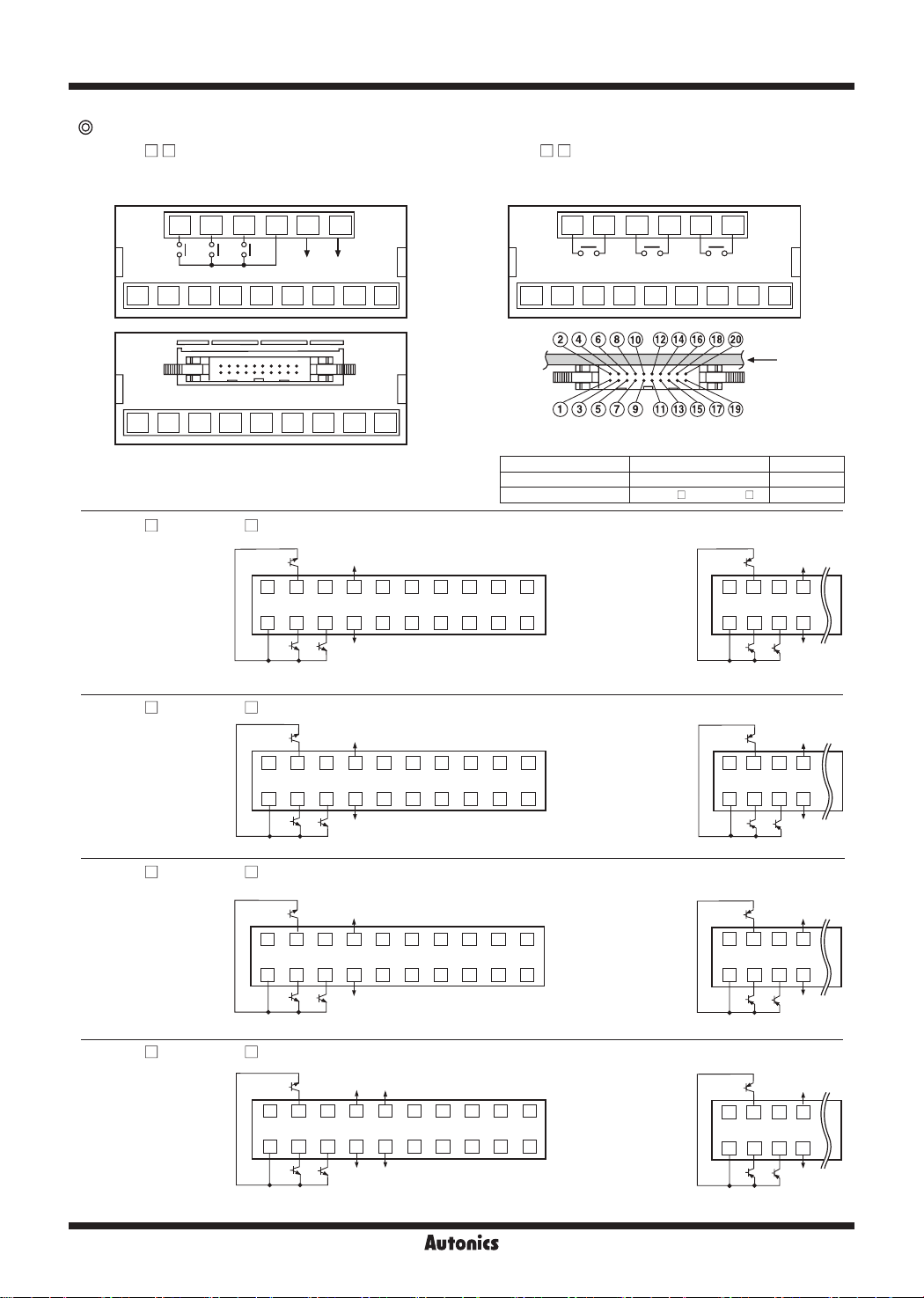
Output terminal connection of MT4W Series
● MT4W- - 0
(triple relay+transmission (DC4-20mA) output)
MAIN OUT
CONTACT OUT
: 250VAC 3A 1a, 30VDC 3A 1a RESISTIVE LOAD
● MT4W- - 1
MAIN OUT
CONTACT OUT
: 250VAC 3A 1a, 30VDC 3A 1a RESISTIVE LOAD
(triple relay output)
10 11 12 13 14 15
HI GO LO COM
1 2 3 4 5 6 7 8 9
1 2 3 4 5 6 7 8 9
● MT4W- -42 / MT4W- -43
GO
MAIN OUT:
NPN OPEN COLLECTOR
12-24VDC Max. 50mA
2 4 6 8 10 12 14 16 18 20
1 3 5 7 9 11 13 15 17 19
COM1 HI LO
● MT4W- -44 / MT4W- -45 (
GO
MAIN OUT:
NPN OPEN COLLECTOR
12-24VDC Max. 50mA
2 4 6 8 10 12 14 16 18 20
COM1 HI LO
+
-
DC4-20mA
Load 600Ω Max.
HI GO LO
1 2 3 4 5 6 7 8 9
10 11 12 13 14 15
※
Hirose connector: HIF3BA-20D-2.54R
※
Connector socket specification: Contact the manufacture for the
socket and cable.
Connector socket HIF3BA-20D-2.54R Hirose Electric
I/O cable (Sold separately) CO20-HP
Specifications Manufacture
(triple NPN/PNP open collector+BCD dynamic output)
+24VDC
30mA Max.
0V
A C D0 D2
BCD OUT:
NPN OPEN COLLECTOR
12-24VDC Max. 50mA
COM2DOTD3D1DB
MAIN OUT:
PNP OPEN COLLECTOR
12-24VDC Max. 50mA
POL
※
POL: When a display value is "-", the signal of "-" will be
outputted.
triple NPN/PNP open collector+transmission (DC4-20mA) output)
+24VDC
30mA Max.
9 11 13 15 17 191 3 5 7
0V
(-)
(+)
Current:
DC4-20mA LOAD 600Ω Max.
MAIN OUT:
PNP OPEN COLLECTOR
12-24VDC Max. 50mA
PCB
-L, CO20-HP -R Autonics
+24VDC
GO
COM1 HI LO
COM1 HI LO
30mA Max.
2 4 6 8
1 3 5 7
+24VDC
30mA Max.
GO
2 4 6 8
1 3 5 7
0V
0V
● MT4W- -46 / MT4W- -47
MAIN OUT:
NPN OPEN COLLECTOR
12-24VDC Max. 50mA
COM1 HI LO
● MT4W- -48 / MT4W- -49
MAIN OUT:
NPN OPEN COLLECTOR
12-24VDC Max. 50mA
COM1 HI LO
O-28
(triple NPN/PNP open collector+low speed serial output)
※
+24VDC
GO
2 4 6 8 10 12 14 16 18 20
1 3 5 7 9 11 13 15 17 19
30mA Max.
0V
POL: When a display value is "-", the signal of "-" will be
outputted.
CLOCKPOL
LATCH
MAIN OUT:
PNP OPEN COLLECTOR
12-24VDC Max. 50mA
DATA
COM2
SERIAL OUT:
NPN OPEN COLLECTOR
12-24VDC Max. 50mA
(triple NPN/PNP open collector+RS485 communication output)
+24VDC
RS485
30mA Max.
GO
2 4 6 8 10 12 14 16 18 20
1 3 5 7 9 11 13 15 17 19
B (-)
SG
SG
※
0V
A (+)
RS485
SG (Signal Ground)
: Signal ground is the terminal which is base of the
signal voltage. It is connected with terminal 7 inside
of the product.
MAIN OUT:
PNP OPEN COLLECTOR
12-24VDC Max. 50mA
GO
2 4 6 8
1 3 5 7
COM1 HI LO
GO
2 4 6 8
1 3 5 7
COM1 HI LO
+24VDC
30mA Max.
0V
+24VDC
30mA Max.
0V
Page 5
Multi Panel Meter
-|Transparent setting guide|-
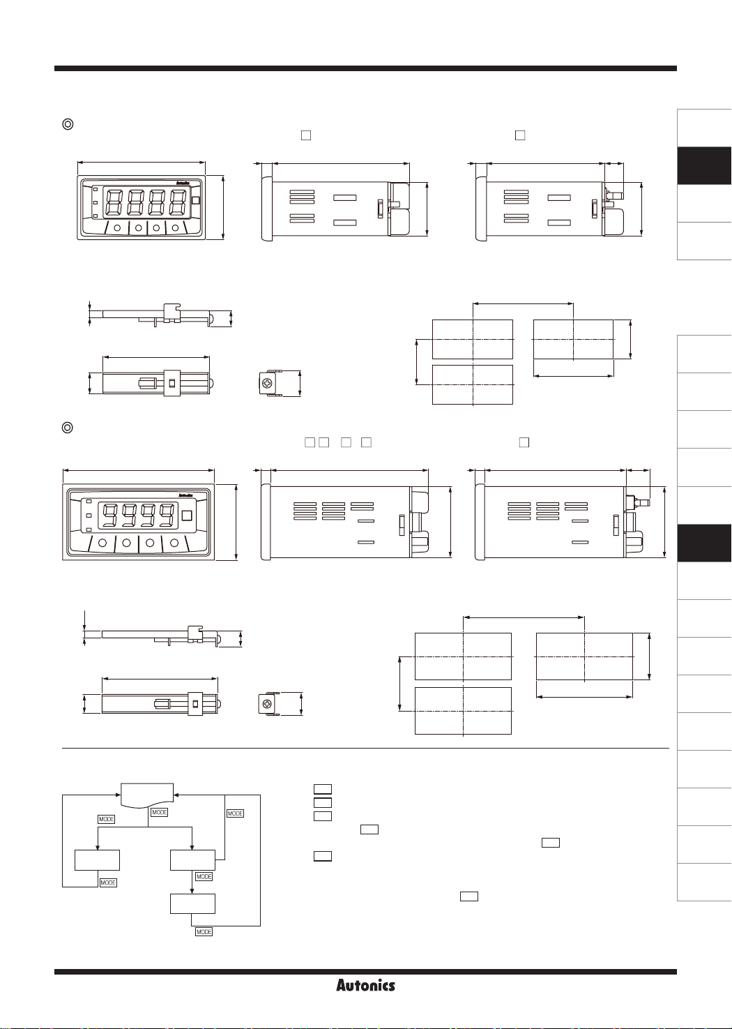
▣ Dimensions
MT4Y Series
72
● Bracket
4
60
12
MT4W Series
96
● MT4Y-
6
36
9
14.5
● MT4W- - N/ 0/ 1
6 6100 89.5
48
-4N/40~44/46
77
30.2
● Panel cut-out
Min. 40
45
● MT4Y-
6
Min. 91
● MT4W-
-45
66.5
-42 to 49
(unit: mm)
SENSORS
10.5
0
+ 0.5
31.5
+ 0.7
68
0
14.9
30.2
CONTROLLERS
MOTION DEVICES
SOFTWARE
(J)
Temperature
Controllers
(K)
SSRs
(L)
Power
Controllers
(M)
Counters
(N)
Timers
45
(O)
Digital
Panel Meters
● Bracket
4.412
73
▣ Parameter Setting
RUN
3 sec
PA 0
PA1
2 sec
PA2
3 sec
3 sec
(P)
Indicators
● Panel cut-out
Min. 116
10
+ 0.8
92
Min. 52
0
14.5
※
※
※
※
※
MODE
Press
Press
Press
When pressing
key in RUN mode and it enters PA 0 group.
MODE
key for over 3 sec in RUN mode, it displays [
MODE
key for over 5 sec in RUN mode, it displays [
MODE
key continually, it stops displaying at [
It is advanced to current display parameter releasing
MODE
Press
key for over 3 sec in any parameter groups, it returns to RUN
PA1
PA2
MODE
].
] after [
PA2
key at [
].
PA1
].
] or [
PA1
mode.
※
If any key is not entered for 60 sec in each parameter, it returns to RUN mode.
※
After returning to RUN mode, press
MODE
key within 2 sec, it returns to previous
parameter. (Refer to the below descriptions of each parameter group.)
※
PA 0 group cannot be entered when preset output mode of [
.
OFF
PA2
] group is
0
+ 0.6
45
PA2
].
(Q)
Converters
(R)
Digital
Display Units
(S)
Sensor
Controllers
(T)
Switching
Mode Power
Supplies
(U)
Recorders
(V)
HMIs
(W)
Panel PC
(X)
Field Network
Devices
O-29
Page 6
MT4Y/MT4W Series
-|Transparent setting guide|-
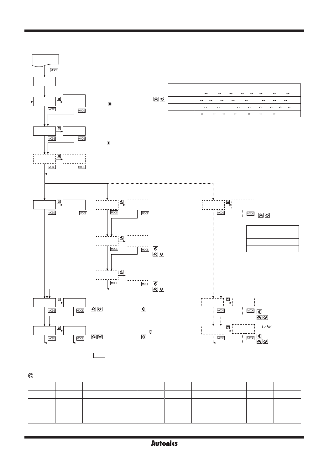
▣ Parameter 1 Group
RUN
3 sec
PA1
IN-R
Display of factory
default for
measurement input
Select measurement input specification by
Refer to "
-
Measurement Input".
● Measurement input chart by model
Item Range of measurement input
MT4Y/W-DV
.
MT4Y/W-DA
MT4Y/W-AV
MT4Y/W-AA
※
Standard specification. (110P is 440VAC/110VAC P.T)
500V
100V
50V
10V
5A 2A )5A )2A 50MA 4-20MA 5MA 2MA 5A
500V
250V
110P
(※)
5A 2.5A 1A )5A )25A )1A 50mA 5
50V
5V
20V
1V
)25V
10V
2V
50ㅡMV
1V
500V
500V
A
DISP
IN-T
When
STND
INbH
STND
AVG
is
DISP
STND
Max. display
value
It shows Max. display
value of standard
specification.
Display value is fixed.
!000
INbL 00
Refer to "
-
(
Select measurement method for AC.
Setting range:
(This parameter will be displayed only for AC measurement models.
In case of selecting frequency display, it will not be displayed.)
It corrects a gradient of High-limit display value against max. input.
Setting range:
(
It corrects deviation of Low-limit display value against Min. input.
Setting range:
(
Measurement Input".
mode is only for AC measurement type.)
FREQ
(average: AVG, root mean square: RMS)
AVG, RMS
When
DOT
H-SC
L-SC
: change setting value, : shift the digit)
: set a deviation value, : shift the digit)
is
DISP
SCAL
Decimal point
position
Max. display
Min. display
to
)100
%000
to 99 (Refer to " Zero adjustment ".)
-99
Select decimal point position.
Setting range
: 0,
※
position, "
decimal point position.
Set display value against
max. measurement input.
value
(
Set display value against
min. measurement input.
value
(
(%)
)0, )00, )000
When selecting the decimal point
: shift the digit
: change setting value)
: shift the digit
: change setting value)
H-SC
",
" have
L-SC
When
(It is only displayed for AC measurement type.)
DOT
is
DISP
Decimal point
position
FREQ
Set frequency measurement
range, it is decided as
the decimal point position.
(
change the
decimal point position)
0
)0
)00
)000
※
In case of selecting frequency display, no
output will be provided even if it is output
support models (main output, Sub output
and RS485 communication output).
It corrects a gradient of display
INbH
INbE
!000
10-0
value against max.input.
Setting range: 0.001 to 9.999
( : shift the digit,
: change setting value)
Set
Setting range: 10
: shift the digit,
(
: change setting value)
1 to 9999Hz
0.1 to 999.9Hz
0.10 to 99.99Hz
0.100 to 9.999Hz
-2
to 101
※
After setting each mode, press
※
If any key is untouched for 60 sec after advance to parameter, it will return to RUN.
MODE
key for 2 sec to return to RUN.
Factory defaults
Parameter MT4Y/W-DV MT4Y/W-DA MT4Y/W-AV MT4Y/W-AA Parameter MT4Y/W-DV MT4Y/W-DA MT4Y/W-AV MT4Y/W-AA
IN-R 500V SA 500V SA INbH !000 !000 !000 !000
DISP STND STND STND STND INbL 00 00 00 00
IN-T
STND 50)0 %000 50)0 %000 INbE
O-30
- -
AVG AVG DOT )0 )000 )0 )000
- -
10-0 10-0
Page 7

Multi Panel Meter
-|Transparent setting guide|-
▣ Parameter 2 Group
RUN
5 sec
PA2
Move after 1 sec
OUtT
HYS
STaT
PEkT
D1sT
OFF
001
0)0
00 5
)2 5
ZERO
EV1N HOLD
FS-H
FS-L
50)0
00)0
ADRS
BPS
PRTY
9600
NONE
STP
RSwT 5
LOC OFF
※
The dotted mode is only displayed for output type.
※
After setting each mode, press
※
If any key is untouched for 60 sec after advance to parameter, it will return to RUN mode.
Factory defaults
Parameter MT4Y/W-DV MT4Y/W-DA MT4Y/W-AV MT4Y/W-AA Parameter MT4Y/W-DV MT4Y/W-DA MT4Y/W-AV MT4Y/W-AA
OUtT OFF OFF OFF OFF EV1N HOLD HOLD HOLD HOLD
HYS 001 001 001 001 FS-H 50)0 %000 50)0 %000
STAT 0)0 0)0 0)0 0)0 FS-L 00)0 )000 00)0 )000
PEkT 00 5 00 5 00 5 00 5 ARDS 01 01 01 01
DIsT )2 5 )2 5 )2 5 )2 5 BPS 9600 9600 9600 9600
ZERO NO NO NO NO LOC OFF OFF OFF OFF
Select preset output mode. (only for available models)
Setting range:
※
Only
Set preset hysteresis. The range is within 10% of max. display range (unit: digit).
※
OUtT
Set startup compensation time.
(
Setting range: 0.0 to 99.9 sec
When initially supplying power, delays monitoring of high-limit/low-limit value of display value for the set time.
(
Setting range: 00 to 30 sec
※
If it is set to 00 sec [
parameter 0 group will be not displayed.
Set display cycle and also variable sets by 0.1 sec. (
Setting range: 0.1 to 5.0 sec
Select zero function with operation at front. (set with
NO
When
value is saved automatically at
Select input with 6, 7 (MT4W)[12, 13 (MT4Y)] terminal or zero function for external signal.
(set with
HOLD
Set the high limit value, output point of current output 20mA.
(
(When changing measurement input and prescale mode, it is changed automatically
as maximum value of input range.)
Set the low limit value, output point of current output 4mA.
(
(When changing measurement input and prescale mode, it is changed automatically
as minimum value of input range.)
Set the address of RS485 communication output.
01
(
Setting range: 01 to
Select Baud rate of RS485 communication output.
Setting range:
Set parity bit of RS485 communication.
Setting range:
Set stop bit of RS485 communication.
Setting range: 1,
2
Set response wait time of RS485 communication.
Setting range: 5 to 99
Set key lock function and select from 4 types.
Setting range:
MODE
key for 2 sec to return to RUN mode.
OFF, lST, hST, LhST, HhST, LlST, LdST
setting is available in MT4Y-☐-43 and MT4Y-☐-44 models.
lST
mode is
: shift the digit, : change setting value)
:shift the digit, : change setting value)
+ Key are pressed for 3 sec to set
: Holding display value,
: shift the digit, : change setting value)
: shift the digit, : change setting value)
: shift the digit, : change setting value)
, it is not displayed.
OFF
], parameters of high-peak monitoring value [
00 S
ㅡ INbL
, Key)
9600, 4800, 2400, 1200
NONE, EVEN, ODD
2
OFF, LOC1, LOC2, LOC3
ZERO
99
ㅡㅡㅡYES
mode.
: Zero function using Hold/Zero terminal
]/low-limit monitoring value [
hPEK
: shift the digit, : change setting value)
key)
, it will be zero function and the deviation
Disable to lock keys
OFF
Lock Parameter 1
LOC1
Lock Parameter 1, 2
LOC2
Lock Parameter 0, 1 and 2
LOC3
lPEK
] in the
SENSORS
CONTROLLERS
MOTION DEVICES
SOFTWARE
(J)
Temperature
Controllers
(K)
SSRs
(L)
Power
Controllers
(M)
Counters
(N)
Timers
(O)
Digital
Panel Meters
(P)
Indicators
(Q)
Converters
(R)
Digital
Display Units
(S)
Sensor
Controllers
(T)
Switching
Mode Power
Supplies
(U)
Recorders
(V)
HMIs
(W)
Panel PC
(X)
Field Network
Devices
O-31
Page 8
MT4Y/MT4W Series
-|Transparent setting guide|-
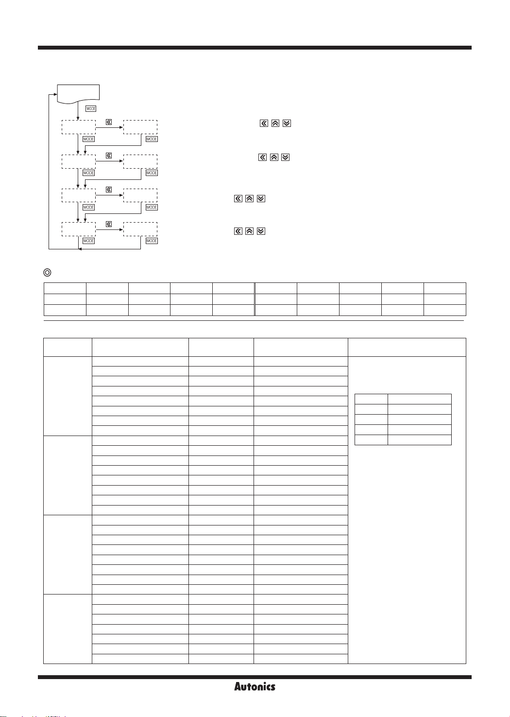
▣ Parameter 0 Group
RUN
hSET
50)0
Set preset High-limit value. (set with , , key)
※
It is displayed when set the preset only.
When set
OFF
in
mode of the parameter 2 group, the parameter is not displayed.
OUtT
lSET
00)0
hPEK
lPEK )0
※
If any key is untouched for 60 sec after advance to parameter, it will return to RUN mode.
Set preset Low-limit value. (set with
※
It is displayed when set the preset only.
When set
It shows High-limit monitoring value while it is in RUN mode.
)0
It will be reset by pressing
※
hPEK
It shows Low-limit monitoring value while it is in RUN mode.
It will be reset by pressing
※
lPEK
in
OFF
parameter is not displayed when
parameter is not displayed when
mode of the parameter 2 group, the parameter is not displayed.
OUtT
, , key)
, , key.
, , key.
parameter is set as 00 sec [
PEkT
parameter is set as 00 sec [
PEkT
] at the parameter 2 group.
00 5
] at the parameter 2 group.
00 5
Factory defaults
Parameter MT4Y/W-DV MT4Y/W-DA MT4Y/W-AV MT4Y/W-AA Parameter MT4Y/W-DV MT4Y/W-DA MT4Y/W-AV MT4Y/W-AA
hSET 50)0 %000 50)0 %000 hPEK )0 )000 )0 )000
lSET 00)0 )000 00)0 )000 lPEK )0 )000 )0 )000
▣ Measurement Input
Type Measurement input and range Input impedance Display range [
500V
] 4.33MΩ 0.0 to 500.0 (xed)
100V
] 4.33MΩ 0.0 to 100.0 (xed)
50V
] 433.48kΩ 0.00 to 50.00 (xed)
10V
] 433.48kΩ 0.00 to 10.00 (xed)
)25V
] 2.28kΩ 0.0 to 250.0 (xed)
50MV
] 2.28kΩ 0.00 to 50.00 (xed)
)5A
] 0.22Ω 0.0 to 500.0 (xed)
)2A
] 0.22Ω 0.0 to 200.0 (xed)
50MA
] 2.22Ω 0.00 to 50.00 (xed)
4-20
] 2.22Ω 4.00 to 20.00 (xed)
5MA
] 22.22Ω 0.000 to 5.000 (xed)
2MA
] 22.22Ω 0.000 to 2.000 (xed)
500V
] 5.01MΩ 0.0 to 500.0 (xed)
250V
] 5.01MΩ 0.0 to 250.0 (xed)
110P
] 1.11MΩ 0.0 to 440.0 (xed)
50V
] 1.11MΩ 0.00 to 50.00 (xed)
20V
] 200.92kΩ 0.00 to 20.00 (xed)
10V
] 200.92kΩ 0.00 to 10.00 (xed)
2.5A
] 0.02Ω 0.000 to 2.500 (xed)
)5A
] 0.20Ω 0.0 to 500.0 (xed)
)25A
] 0.20Ω 0.0 to 250.0 (xed)
)1A
] 1.02Ω 0.0 to 100.0 (xed)
50MA
] 1.02Ω 0.00 to 50.00 (xed)
" is ashes with a certain measurement input, disconnect power supply and then check the cables.
DC voltage
DC current
AC voltage
AC current
When "
※
0-500V [
0-100V [
0-50V [
0-10V [
0-5V [5V] 43.48kΩ 0.000 to 5.000 (xed)
0-1V [1V] 43.48kΩ 0.000 to 1.000 (xed)
0-250mV [
0-50mV [
0-5A [5A] 0.02Ω 0.000 to 5.000 (xed)
0-2A [2A] 0.02Ω 0.000 to 2.000 (xed)
0-500mA [
0-200mA [
0-50mA [
4-20mA [
0-5mA [
0-2mA [
0-500V [
0-250V [
0-110V [
0-50V [
0-20V [
0-10V [
0-2V [2V] 20.92kΩ 0.000 to 2.000 (xed)
0-1V [1V] 20.92kΩ 0.000 to 1.000 (xed)
0-5A [5A] 0.02Ω 0.000 to 5.000 (xed)
0-2.5A [
0-1A [1A] 0.10Ω 0.000 to 1.000 (xed)
0-500mA [
0-250mA [
0-100mA [
0-50mA [
HHHH
" or
"LLLL
O-32
] Prescale display range [
STND
DOT
0
)0
)00
)000
(Display range is variable according
to decimal point position.)
※
Connect to the input terminals
whose 30% to 100% of the input
range includes the max. value of
the input range to measure.
When the max. input value
is under the 30% of the input
terminal range, display accuracy
is degraded.
When the max. input value is over
the 100%, it may result in input
terminal damage.
In case of 0 to 110V [
※
AC voltage range and using
P.T (potential transformer) for
440V/110VAC, if 110V is input,
and the unit displays 440V
automatically by preset scale
value for P.T user's convenient.
SCAL
Display range
-1999 to 9999
-199.9 to 999.9
-19.99 to 99.99
-1.999 to 9.999
110P
]
] of
Page 9
-|Transparent setting guide|-
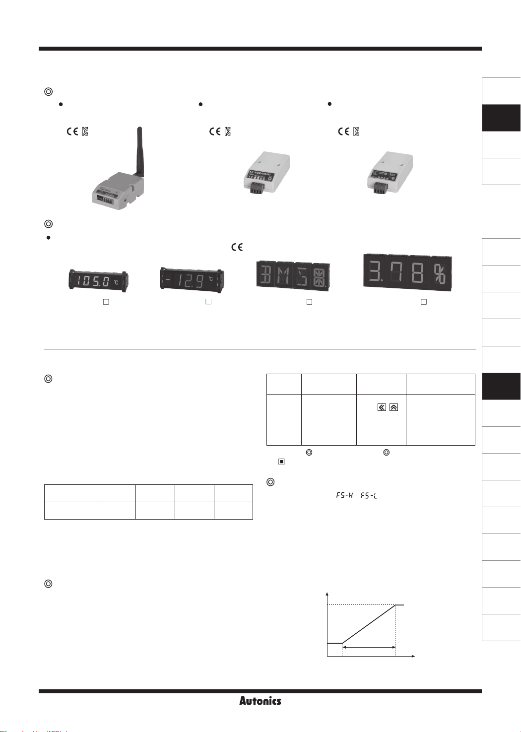
Sold Separately
▣
Communication converter
SCM-WF48
( Wi-Fi to RS485·USB wireless
communication converter)
SCM-US48I
(USB to RS485 converter)
Display Units (DS/DA-T Series)
DS/DA-T Series
(RS485 communication input type display unit)
Multi Panel Meter
SCM-38I
(RS232C to RS485 converter)
SENSORS
CONTROLLERS
MOTION DEVICES
SOFTWARE
(J)
Temperature
Controllers
(K)
SSRs
DS16- T
※
Connect RS485 communication input type display unit (DS/DA-T Series) and RS485 communication output model of MT4Y/MT4W Series,
the display unit displays present value of the device without PC/PLC.
DS22/DA22- T
DS40/DA40- T DS60/DA60- T
▣ Functions
AC frequency measurement
[PA 1 group:
It measures input signal frequency when it is AC input.
It uses fixed decimal point [PA1 :
can be changed by setting and measured range of decimal
point position is as below chart. It is available to adjust the
upper gradient at [PA 1:
measure frequency normally, input signal, over 10% F.S. of
the measured range, should be supplied. Please select the
proper point of
Measurement range
①
Decimal point
position
Measurement
range
※
Accuracy of frequency measurement:
Below 1kHz, F.S. ±0.1rdg ±2-digit.
From 1kHz to 10kHz, F.S. ±0.3rdg ±2-digit.
INbH
②
③
: 0.100 to 9.999 [Gradient adjustment of high value]
INbE:
10
DISP
]
DOT
], measured range
INbH
]and [PA 1:
0.000 0.00 0.0 0
0.100 to
9.999Hz
-2
, 10-1, 100, 101 [Index adjustment of
0.10 to
99.99Hz
INbE
0.1 to
999.9Hz
]. In order to
1 to
9999Hz
INbH
]
Zero adjustment
[Deviation correction function of low limit
display value]
It adjusts the display value of the optional configured input
value as zero by force, zero point error can be adjusted
with 3 ways as below. When zero point adjustment with
front key and Hold terminal is finished normally, zero point
of measurement terminal is displayed and the adjusted
value at saved in
INbL
automatically.
Operation
Description
※
It sets transmission output for the display value at the
output current DC4-20mA.
It sets display value for 4mA at
and the range between
※
※
Refer to "
Input correction
value
PA 1: Direct
input correction
value method at
INbL
.
Error correction", " Error display" and
Front panel
key
Press ,
key for 3 sec
at the
RUN mode.
Input external signal
Short-circuit external
Hold terminal 11,12
[6, 7 (MT4W)] over
min. 50m.
" Parameter 2 Group" for function and error.
Transmission (DC4-20mA) output scale
[PA2 group:
When min. set interval between
set as under 10% F.S., it changed as over 10% F.S.
automatically.
Preset display value is fixed to output as 4mA at under
FS-L
and 20mA at over
Output
20mA
4mA
]
/
FS-L
FS-H
and
FS-L
FS-H
FS-H
.
Min.
setting range
F.S. 10%
FS-L FS-H
and 20mA at
should be 10%
FS-L
and
Display value
FS-H
is
(L)
Power
Controllers
(M)
Counters
(N)
Timers
(O)
Digital
Panel Meters
(P)
Indicators
(Q)
Converters
(R)
Digital
Display Units
(S)
Sensor
Controllers
(T)
Switching
Mode Power
Supplies
(U)
Recorders
(V)
HMIs
(W)
Panel PC
(X)
Field Network
Devices
O-33
Page 10
MT4Y/MT4W Series
-|Transparent setting guide|-
Initialization
It initializes as the factory default status.
If press , , keys together for 2 sec in RUN mode,
is displayed and press , , keys, (NO) will flash
INIT
every 0.5 sec. It will be initialized as the factory default
when press
key after change
MODE
NO→ YES
.
Startup compensation time
This time function limits
[PA 2 group:
STAT
]
the operation of an output until the measured input
(overvoltage or inrush current) is stable at moment
of power on. All outputs are off during startup
compensation time setting after power is applied.
Setting range: 00.0 to 99.9 (unit: sec)
Factory default: 00.0
Error display
Display Description
Flashes when measured input is exceeded the max. allowable
HHHH
input (110%)
Flashes when measured input is exceeded the min. allowable
LLLL
input (-10%)
Turns ON when display input is exceeded the max. display range (9999)
D-HH
or
setting value
H-SC
Turns ON when display input is exceeded the min. display
D-LL
range (-1999) or
Turns ON when input frequency is exceeded the max. display
F-HH
value of measurement range
Flashes when it exceeds zero range (±99)
OVER
※
Error display is released automatically when it is in the
measured and display range.
※
"
" is displayed when the input specification is DC.
LLLL
※
After flashing "
adjustment range, it returns to RUN mode.
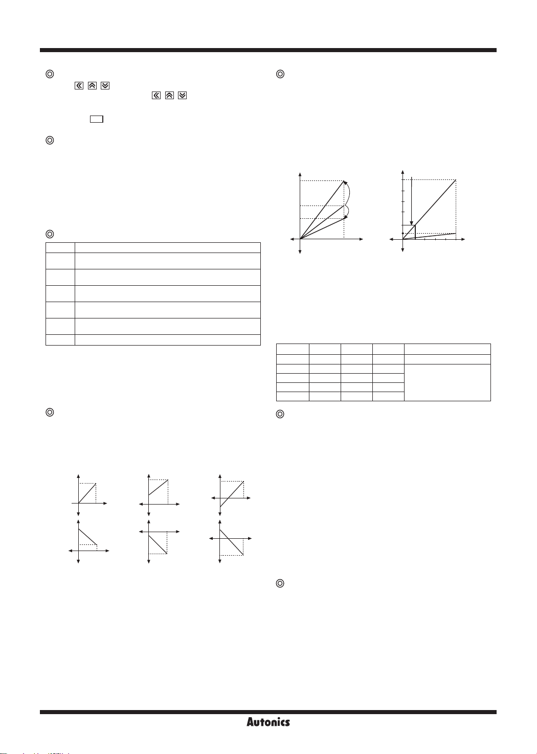
Display scale [PA 1 group:
This function is to display setting (-1999 to 9999) of
particular High/Low-limit value in order to display High/Lowlimit value of measured input. If measured inputs are 'a' and
'b' and particular values are 'A' and 'B', it will display a=A,
b=B as below graphs.
B
Display
value
A
a b
Input value
Display
A
value
B
b
a
Input value
setting value
L-SC
" 2 times when it exceeds the zero
OVER
H-SC/L-SC
B
Display
value
Display
value
A
a
Input value
a
A
B
Input value
Display
value
b
b
Display
value
]
B
a
A
Input value
A
a
B
Input value
b
b
Gradient correction [PA 1 group:
INbH
]
This function is to correct a gradient of prescale value and
display value. (Fig.1) Display value Y can be used as α, β
times against X input value by correction function [
INbH
].
And also can be used as correction function of max.
display value (
). Adjustment range is 0.100 to 5.000
H-SC
and multiply current gradient.
E.g.) Input: DC200mV, Display: 3.000 for MT4W-DV
Display value for
αY
α time
Y
βY
Display value
0
(Fig. 1)
Select 0-1VDC[1V] for measurement input in Parameter1.
①
Standard specification in input: 0-1VDCᜡ and 1.000
②
X
β time
Input
value
therefore it has to be 15.000 (
measuring input
15.000
12.000
9.000
6.000
3.000
Display value
1.000
0.2 0.4 0.60.8 1V
(example of gradient correction)
H-SC
) for 1VDCᜡ (input)
Input
value
in order to display 3.000 for 200mVDCᜡ (input). But it
is disable due to setting range is 9.999
In this case, please check below chart.
③
Please set as
Setting
①
②
③
④
⑤
Error correction [PA 1 group:
INbH× H-SC
=15.000
H-SC L-SC INbH
Disable 0.000 1.000
7.500 0.000 2.000
5.000 0.000 3.000
3.750 0.000 4.000
3.000 0.000 5.000
Other
-
In this case, any setting
methods display the
same display value.
INbH
INbL
/
]
It corrects display value error of measured input.
: ±99 [Adjust deviation of low value]
INbL
: 5.000 to 0.100 [Correct gradient (%) of high value]
INbH
Display value= (measured value ×
INbH
) +
INbL
E.g.) When the measured range is 0 to 500V, and the
display range is 0 to 500.0. If the low display value is "
to 0V input, set -12 as
value to display ")0" by
INbL
1.2
adjusting offset of the low value. The display value to 500V
measured input varies by adjusting the offset of low value.
If this display value is "
", calculate 500.0/501.0
501.0
(desired display value/the display value), and set the 0.998
correction value as the
INbH
to display
50)0
by adjusting
gradient of high value.
※
The offset correction range of
for D-0, D
-1
digit regardless of decimal point.
is within -99 to 99
INbL
"
O-34
Display cycle delay [PA 2 group:
D1sT
]
In some applications the measured input may fluctuate
which in turn causes the display to fluctuate. By adjusting
the display cycle delay function time in the
D1sT
of
parameter 2, the operator can adjust the display time within
a range of 0.1 sec to 5 sec. For example, if the operator
sets the display cycle time to 4.0 sec, the display value
displayed will be the average input value over 4 sec and
also will show any changes if any every 4 sec.
Page 11
Multi Panel Meter
-|Transparent setting guide|-
Monitoring peak display value
[PA 0 group:
hPEK/lPEK
, PA 2 group:
It monitors max./min. value of display value based on the
current displays value and then displays the data at
lPEK
of parameter 0. Set the delay time (0 to 30 sec)
PEkT
at
of parameter 2 in order to prevent malfunction
caused by initial overcurrent or overvoltage, when
monitoring the peak value.
Delay time is 0 to 30 sec and it starts to monitor the peak
value after the set time. When pressing any one of
hPEK, lPEK
keys at
of parameter 0, the monitored data
is initialized.
※
hPEK, lPEK
monitoring delay time [
as 00 sec [
parameters is not displayed when
PEkT
00 S
].
] of parameter 2 group is set
PEkT
hPEK
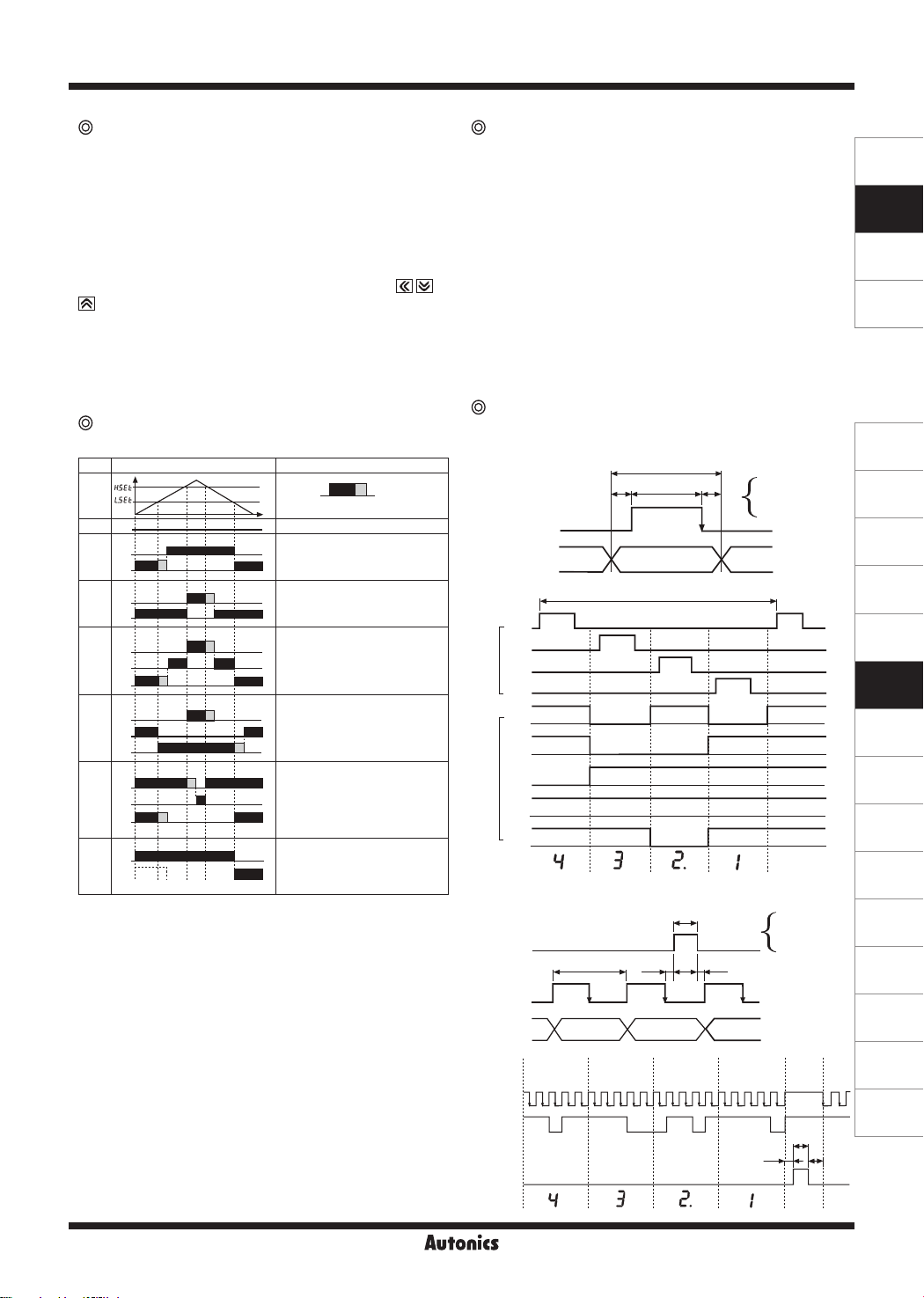
Preset output operation mode
[PA 2 group:
Mode Output operation Operation
OFF
GO
lST
LO
H
HI
hST
GO
HI
LhST
GO
LO
H
HI
HhST
GO
LO
HI
GO
LlST
LO
GO
LdST
LO
※
"H" means hysteresis and able to set 1 to 99 at "
mode in PA 2 among above comparison output chart.
※
is displayed according to the setting of output
hSET
operation mode, when user sets "
not displayed.
※
Only
lST
MT4Y-☐-44 models.
H
H
H
setting is available in MT4Y-☐-43 and
OUtT
H
H
H
]
H: Hysteresis
No output
If it is equal or smaller than low
setting value, LO output will be ON.
If it is bigger than low setting value,
GO output will be ON.
If it is equal or bigger than high
setting value, HI output will be ON.
If it is equal or smaller than high
setting value, GO output will be ON.
If it is equal or smaller than low
setting value and equal or bigger
than high setting value, the output
will be ON. If it is bigger than Low
setting value and smaller than high
setting value, GO output will be ON.
If it is equal or bigger than low set
and equal or bigger than high set
value, output will be ON. If it is
smaller than low setting value and
high setting value, GO output will
H
be ON.
If it is equal or smaller than low
setting value, LO output will be ON.
If it is equal or smaller than high
setting value, HI output will be ON.
If it is bigger than low setting value
and High setting value, GO output
will be ON.
This operation is the same as
But it doesn't operate at initial low
set value, it will operate at next low
set value. If this is higher than low
set value, Go output will be ON.
",
OFF
hSET/ lSET
H
lST
"
HYS
Sub output
● RS485 communication output
]
It is able to set address (01 to 99)
It is able to transmit by selecting modulation speed
,
(transmitted number of signal per 1 sec) of serial trans
-mission. (selectable 1200, 2400, 4800, 9600bps)
● Low-speed serial output
It outputs current display value as Low-frequency (50Hz)
type.
● Transmission (DC4-20mA) output
It outputs DC4-20mA against High/Low-limit scale.
(resolution: 12000 division)
● BCD dynamic output
It outputs display value as BCD Code.
※
Only one sub-output is selectable.
(More than one sub-output is not allowed.)
Time chart of BCD dynamic output and
Serial output
● BCD dynamic output (negative logic)
Digit signal
Input Data
D3
D2
Digit
D1
D0
A
H L H L H
B
H L L H H
C
Data
L H H H H
D
H H H H H
Hdot
Display
● Serial output (negative logic)-Clock frequency:50Hz
are
Latch
Clock
Data
Input
ordering
Clock
Data
Latch
Display
Cn-1
Dn-1 Dn D1
12345
DP D C B A
HHLHH HHHLL LHHLH HHHHL
6 7 8 9 10
DP D C B A
t
ta tw
Data
31.2ms
H L H H
tw
tat
Cn C1
11 12 13 14 15
DP D C B A
tb
tb
16 17 18 19 20
DP D C B A
t: 7.8ms
ta: 0.5ms
tw: 5ms
tb: 2.3ms
t: 20ms
ta: 0.05ms
tw: 5ms
tb: 4.95ms
tw
ta
tb
1 2
DP D
SENSORS
CONTROLLERS
MOTION DEVICES
SOFTWARE
(J)
Temperature
Controllers
(K)
SSRs
(L)
Power
Controllers
(M)
Counters
(N)
Timers
(O)
Digital
Panel Meters
(P)
Indicators
(Q)
Converters
(R)
Digital
Display Units
(S)
Sensor
Controllers
(T)
Switching
Mode Power
Supplies
(U)
Recorders
(V)
HMIs
(W)
Panel PC
(X)
Field Network
Devices
O-35
 Loading...