

Page 1
MP5S/MP5Y/MP5W Series
-|Transparent setting guide|-
High Performance, Digital Pulse Meter
Features
▣
Total 16 types of operation mode
Frequency/Revolutions/Speed, Passing speed, Cycle, Passing time,
Time interval, Time dierential , Absolute ratio, Error ratio, Density,
Error, Length measurement 1, Length measurement 2, Interval,
Accumulation, Addition/Subtraction-individual input, Addition/
Subtraction-phase dierence input
Various output models
Relay triple/quintuple output, NPN/PNP open collector quintuple output,
BCD dynamic output, PV transmission output (current output),
RS485 communication output (Modbus RTU)
Various functions
Selectable NPN solid state/contact input, PNP solid state/contact
input, prescale, delay monitoring, hysteresis, auto-zero time
setting, lock setting, data bank function (MP5W series)
Max. display range: -19999 to 99999
Various display units
rpm, rps, Hz, kHz, sec, min, m, mm, mm/s, m/s, m/min, m/h, ℓ/s,
ℓ/min, ℓ/h, %, counts, etc.
Please read “Safety Considerations”
in the instruction manual before using.
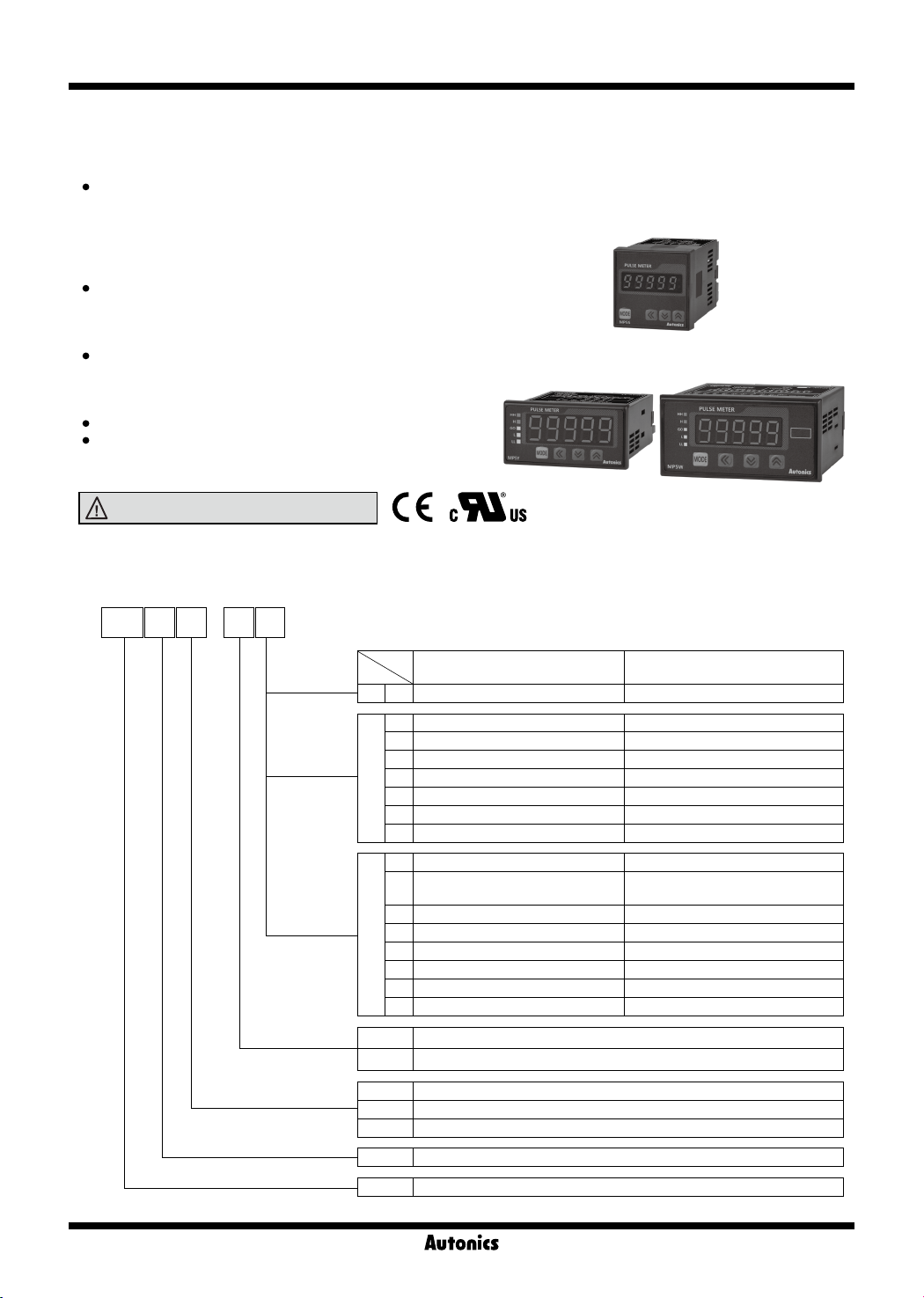
MP5S
MP5Y MP5W
▣ Ordering Information
-
MP 5 Y 4
Size
Digits
Item
N
Output
Power supply
Main output
(comparative value output)
S N Indicator
N Indicator
1 NPN open collector quintuple output
2 PNP open collector quintuple output
Y
3 Indicator BCD dynamic output
4 Indicator PV transmission output (current output)
5 Indicator RS485 communication output
6 Relay triple output (H, GO, L)
N Indicator
Relay quintuple output
A
(HH, H, GO, L, LL)
1 Relay triple output (H, GO, L)
2 NPN open collector quintuple output BCD dynamic output
W
4 NPN open collector quintuple output PV transmission output (current output)
5 PNP open collector quintuple output PV transmission output (current output)
8 NPN open collector quintuple output RS485 communication output
9 PNP open collector quintuple output RS485 communication output
2 24VAC 50/60Hz, 24-48VDC
4 100-240VAC 50/60Hz
S DIN W48×H48mm
Y DIN W72×H36mm
W DIN W96×H48mm
5 99999 (5-digit)
MP Pulse meter
Sub output
(display value output)
-
-
-
-
-
-
-
-
O-76
Page 2
Pulse Meter
-|Transparent setting guide|-
Specications
▣
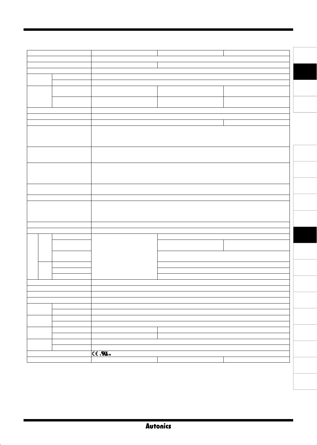
Series MP5S MP5Y MP5W
Display method 7-segment LED (zero blanking method)
Character size W4×H8mm W7×H14mm
Display range -19999 to 99999
Power
supply
Power
consumption
Permissible voltage range 90 to 110% of rated voltage
External power supply Max. 12VDCᜡ ±10% 80mA
Sub power supply
Input frequency
Input method
Measurement range
Measurement accuracy
(23℃±5℃)
Display cycle OFF (for F2, F16 operation mode), 0.05, 0.5, 1, 2, 4, 8 sec (same as update output cycle)
Operation mode
Prescale function Direct input method (0.0001×10
Hysteresis 0 to 9999
Output
Memory retention Non-volatile memory (number of inputs: 100,000 operations)
Insulation resistance Over 100MΩ (at 500VDC megger)
Dielectric strength 2,000VAC 60Hz for 1 min
Noise immunity ±2kV the square wave noise (pulse width: 1㎲) by the noise simulator
Vibration
Shock
Relay
life cycle
Environ-
ment
Approval
Weight
※
1: Setting range will vary depending on the decimal point.
※
2: The weight includes packaging. The weight in parenthesis is for unit only.
※
Environment resistance is rated at no freezing or condensation.
AC voltage 100-240VACᜠ 50/60Hz
AC/DC voltage 24VACᜠ 50/60Hz, 24-48VDC
AC voltage
AC/DC voltage
Max. 7.5VA
(100-240VACᜠ 50/60Hz)
Max. 6VA (24VACᜠ 50/60Hz),
max. 4.5W (24-48VDCᜡ)
-
Solid state input 1: max. 50kHz (pulse width: min. 10㎲)
·
ᜡ
Max. 9VA
(100-240VACᜠ 50/60Hz)
Max. 7VA (24VACᜠ 50/60Hz),
max. 6.2W (24-48VDCᜡ)
Max. 15VA
(100-240VACᜠ 50/60Hz)
Max. 11VA (24VACᜠ 50/60Hz),
max. 7W (24-48VDCᜡ)
Max. 24VDCᜡ 30mA
·Solid state input 2: max. 5kHz (pulse width: min. 100㎲)
※
Contact input: max. 45Hz (pulse width: min. 11ms)
·
For F7, F8, F9, F10 operation mode, max. 1kHz (pulse width: min. 500㎲)
[Voltage input] High: 4.5-24VDCᜡ, Low: 0-1VDC, Input impedance: 3.9kΩ
[No-voltage input] Short-circuit impedance: max. 80Ω, Residual voltage: max. 1VDC,
Open-circuit impedance: min. 100kΩ
·Operation m
·Operation m
·Operation m
·Operation m
·Operation m
·Operation m
ode F1, F2, F7, F8, F9, F10
ode F3, F4, F5, F6
ode F11, F12, F13, F16
ode F14, F15
ode F1, F2, F7, F8, F9, F10
ode F3, F4, F5, F6
: 0.0005Hz to 50kHz
: 0.01 to max. of each time range
: 0 to 99999
: -19999 to 99999
: F.S.±0.05%rdg±1-digit
: F.S.±0.01%rdg±1-digit
Frequency/Revolutions/Speed (F1), Passing speed (F2), Cycle (F3), Passing time (F4),
Time interval (F5), Time dierential (F6), Absolute ratio (F7), Error ratio (F8), Density (F9), Error (F10),
Length measurement 1 (F11), Interval (F12), Accumulation (F13), Addition/Subtraction-individual input (F14),
Relay triple
Relay quintuple
Main
NPN/PNP open
collector quintuple
Addition/Subtraction-phase dierence input (F15), Length measurement 2 (F16)
※
1
-
-9
to 9.9999×10⁹)
250VACᜠ 3A, 30VDCᜡ 3A resistive load
-
Max. 30VDCᜡ 30mA
250VACᜠ 3A, 30VDCᜡ 3A
resistive load
BCD dynamic Max. 30VDCᜡ 30mA
Sub
PV transmission DC4-20mA/DC0-20mA max. load 500Ω
Communication RS485 communication output (Modbus RTU method)
Mechanical 0.75mm amplitude at frequency of 10 to 55Hz in each X, Y, Z direction for 1 hour
Malfunction 0.5mm amplitude at frequency of 10 to 55Hz in each X, Y, Z direction for 10 min
Mechanical 300m/s² (approx. 30G) in each X, Y, Z direction for 3 times
Malfunction 100m/s² (approx. 30G) in each X, Y, Z direction for 3 times
Mechanical
Electrical
-
-
Ambient temp. -10 to 50℃, storage: -20 to 60
Min. 10,000,000 operations
Min. 100,000 operations (250VAC 3A resistive load)
℃
Ambient humi. 35 to 85%RH, storage: 35 to 85%RH
※
2
Approx. 191g (approx. 132g) Approx. 230g (approx. 140g) Approx. 334g (approx. 210g)
SENSORS
CONTROLLERS
MOTION DEVICES
SOFTWARE
(J)
Temperature
Controllers
(K)
SSRs
(L)
Power
Controllers
(M)
Counters
(N)
Timers
(O)
Digital
Panel Meters
(P)
Indicators
(Q)
Converters
(R)
Digital
Display Units
(S)
Sensor
Controllers
(T)
Switching
Mode Power
Supplies
(U)
Recorders
(V)
HMIs
(W)
Panel PC
(X)
Field Network
Devices
O-77
Page 3
MP5S/MP5Y/MP5W Series
-|Transparent setting guide|-
▣ Connections
※
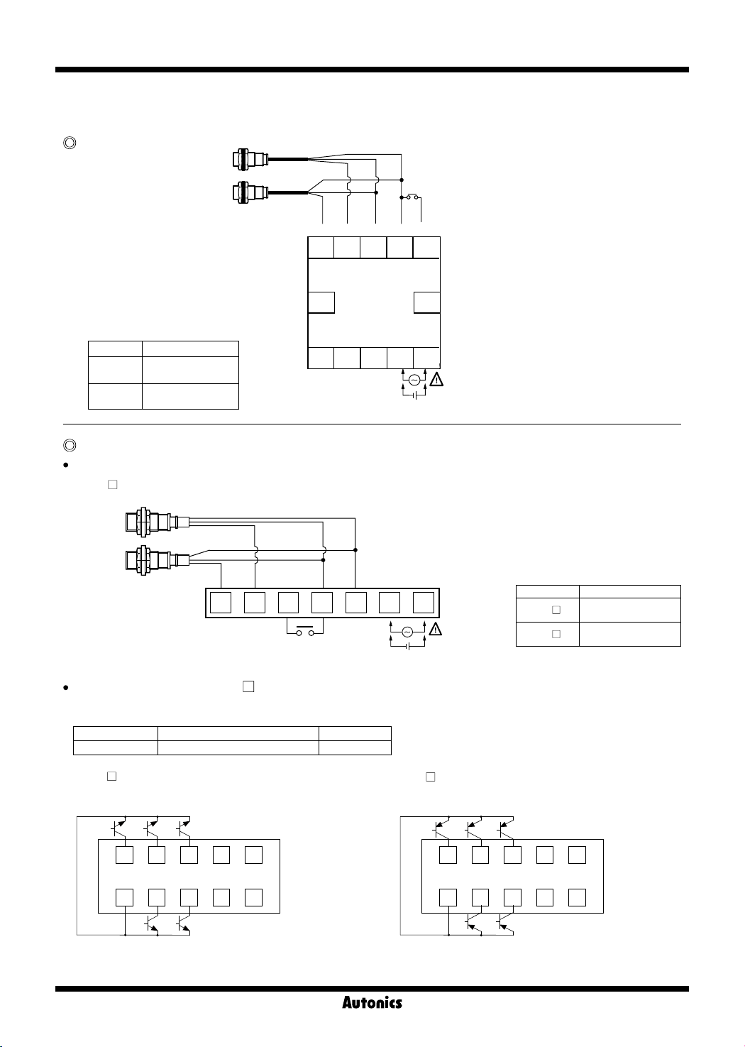
Terminal connections dier by power supply and output type of each series and model.
MP5S Series
※
1: Operation mode F1 to F12
: display value HOLD
Operation mode F13 to F16
: display value RESET
※
2:
Model Source
MP5S-2N
MP5S-4N
24-48VDC
24VAC 50/60Hz
100-240VAC
50/60Hz
MP5Y Series
Power/Input Terminal (Common)
※
MP5Y-
N (indicator) only has 'Power/Input terminals'.
Black Black Blue Brown
1 2 3 4 5 6 7
INA INB
Black
INA
6 7 8 9 10
11
HOLD/RESET
Black
INB
0V +12V
※
1
Brown
+12V
Blue
0V
SOURCE
+-
SOURCE
HOLD/RESET
12
54321
+-
※
2
※
2
※
1
※
1: Operation mode F1 to F12
: display value HOLD
Operation mode F13 to F16
: display value RESET
※
2:
Model Source
MP5Y-2
MP5Y-4
24-48VDC
24VAC 50/60Hz
100-240VAC
50/60Hz
Output Connector (MP5Y-
※
Hirose connector: HIF3BA-10PA-2.54DS
※
Connector socket specification: Contact the manufacture for the socket and cable.
Connector socket HIF3BA-10D-2.54R Hirose Electric
MP5Y-
●
1 (NPN open collector output)
MAIN OUT (NPN OPEN COLLECTOR)
30VDC 30mA
HH
COM H L
Specifications Manufacture
GO LL
2 4 6 8
1 3 5 7
10
9
O-78
1 to 5)
MP5Y-
●
2 (PNP open collector output)
MAIN OUT (PNP OPEN COLLECTOR)
30VDC 30mA
GO LL
HH
2 4 6 8
1 3 5 7
COM H L
10
9
Page 4
Pulse Meter
-|Transparent setting guide|-
MP5Y-
●
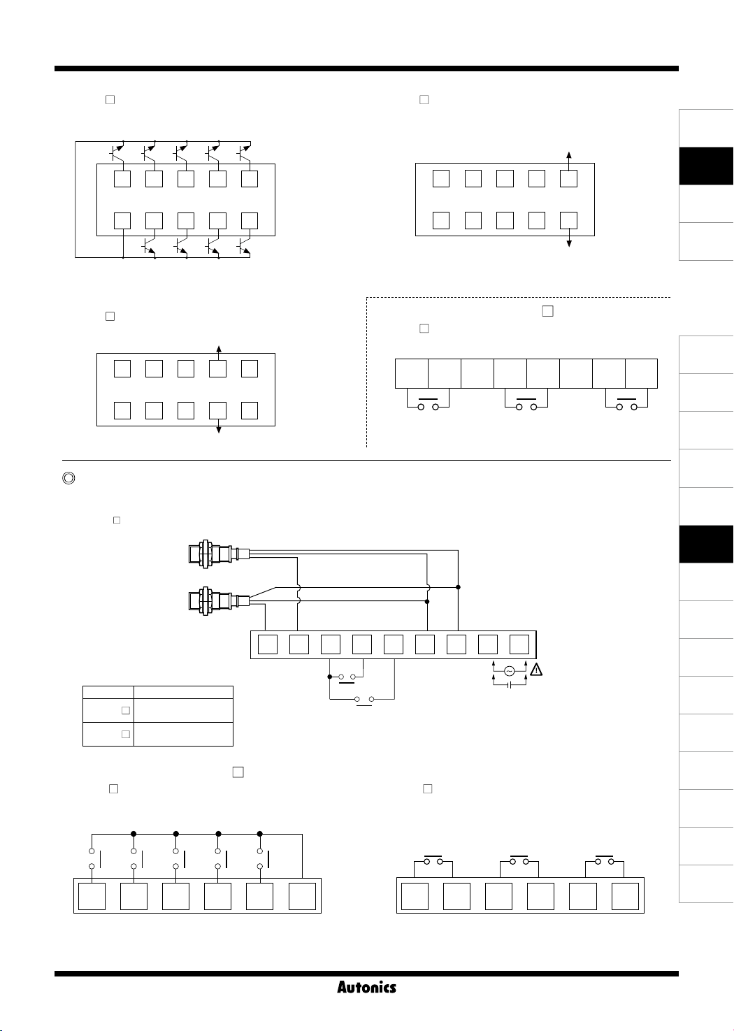
3 (BCD dynamic output)
BCD OUT (NPN OPEN COLLECTOR)
30VDC 30mA
A
C D0 D4D2
2 4 6 8
1 3 5 7
COM B D
※
Autonics display unit (DS/DA Series) is recommended
D1 D3
10
9
for stable minus (-) sign display.
MP5Y-
●
5 (RS485 communication otuput)
RS485 B(-)
2 4 6 8
1 3 5 7
10
9
RS485 A(+)
MP5W Series
●Power/Input Terminal (Common)
※
MP5W-
N (indicator) only has 'Power/Input terminals'.
MP5Y-
●
4 (PV transmission output)
DC4-20mA/DC0-20mA
Load 500Ω Max.
2 4 6 8
1 3 5 7
(+)
10
9
(-)
●Output Terminal (MP5Y-
MP5Y-
●
6 (Relay triple output)
6)
8 9 10 11 12 13 14 15
H GO L
CONTACT OUT:
250VAC 3A, 30VDC 3A RESISTIVE LOAD
SENSORS
CONTROLLERS
MOTION DEVICES
SOFTWARE
(J)
Temperature
Controllers
(K)
SSRs
(L)
Power
Controllers
(M)
Counters
(N)
Timers
(O)
Digital
Panel Meters
Black Black Blue Brown
※
1: Operation mode F1 to F12
: display value HOLD
Operation mode F13 to F16
: display value RESET
※
2:
Model Source
MP5W-2
MP5W-4
●Output Terminal (MP5W-
MP5W-
●
24-48VDC
24VAC 50/60Hz
100-240VAC
50/60Hz
A/1)
A (Relay quintuple output)
CONTACT OUT:
250VAC 3A, 30VDC 3A RESISTIVE LOAD
10 11 12 13 14 15
HH
H GO L LL COM
1
INA INB
2
3 4 5 6 7 8 9
※
1
MP5W-
0V +12V
1 (Relay triple output)
0V
HOLD/RESET
BANK
●
CONTACT OUT:
250VAC 3A, 30VDC 3A RESISTIVE LOAD
H GO L
10 11 12 13 14 15
+-
SOURCE
(P)
Indicators
(Q)
Converters
(R)
Digital
Display Units
(S)
※
2
Sensor
Controllers
(T)
Switching
Mode Power
Supplies
(U)
Recorders
(V)
HMIs
(W)
Panel PC
(X)
Field Network
Devices
O-79
Page 5
MP5S/MP5Y/MP5W Series
-|Transparent setting guide|-
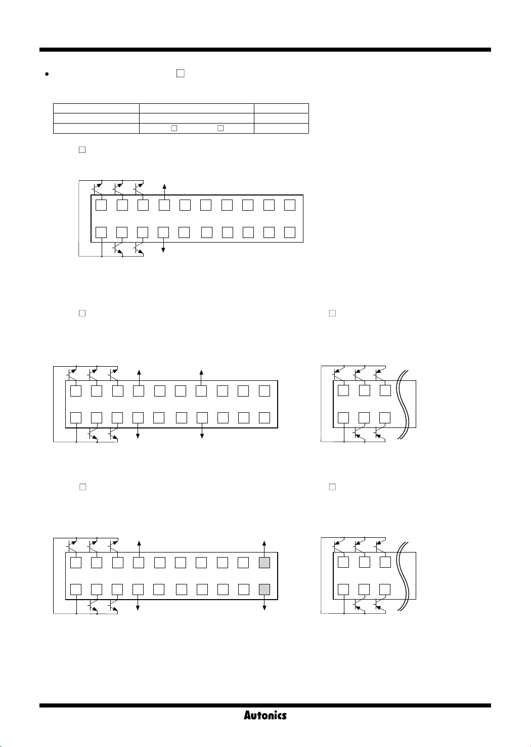
Output Connector (MP5W-
※
Hirose connector: HIF3BA-20PA-2.54DS
※
Connector socket specification: Contact the manufacture for the socket and cable.
Connector socket HIF3BA-20D-2.54R Hirose Electric
I/O cable (sold separately) CO20-HP
MP5W-
●
2 (NPN open collector+BCD dynamic output)
MAIN OUT (NPN OPEN COLLECTOR)
30VDC 30mA
HH
GO
2 4 6 8
1113135157
COM H L
※
1: Sub power supply
※
POL signal turns ON when the display value is a minus (-) value.
2:
※
Autonics display unit (DS/DA Series) is recommended for stable minus (-) sign display.
MP5W-
●
4
Specifications Manufacture
+24VDC
30mA Max.
LL
2/4/5/8/9)
-L, CO20-HP -R Autonics
※
1
D
B D3
10 12 14 16 18 20
A D2
0V
D1
C D4D0 POL
BCD OUT (NPN OPEN COLLECTOR)
30VDC 30mA
DOT COM2
17919
※
MP5W-
●
(NPN open collector+PV transmission output)
MAIN OUT (NPN OPEN COLLECTOR)
30VDC 30mA
HH
GO LL
2 4 6 8
+24VDC
30mA Max.
※
1
(+)
10 12 14 16 18 20
2
5
(PNP open collector+PV transmission output)
MAIN OUT (PNP OPEN COLLECTOR)
30VDC 30mA
GO
LL
HH
2 4 6
1113135157
COM H L
MP5W-
●
8
(NPN open collector+RS485 comm. output)
MAIN OUT (NPN OPEN COLLECTOR)
30VDC 30mA
HH
GO LL
2 4 6 8
1113135157
COM H L
0V
+24VDC
30mA Max.
0V
(-)
DC4-20mA/DC0-20mA
(Load 500Ω Max.)
※
1
10 12 14 16 18
9
17919
RS485
B(-)
20
17
19
A(+)
RS485
1 3 5
COM
MP5W-
●
9
(PNP open collector+RS485 comm. output)
MAIN OUT (PNP OPEN COLLECTOR)
30VDC 30mA
HH
GO
L
H
LL
2 4 6
1 3 5
COM H L
O-80
Page 6
-|Transparent setting guide|-
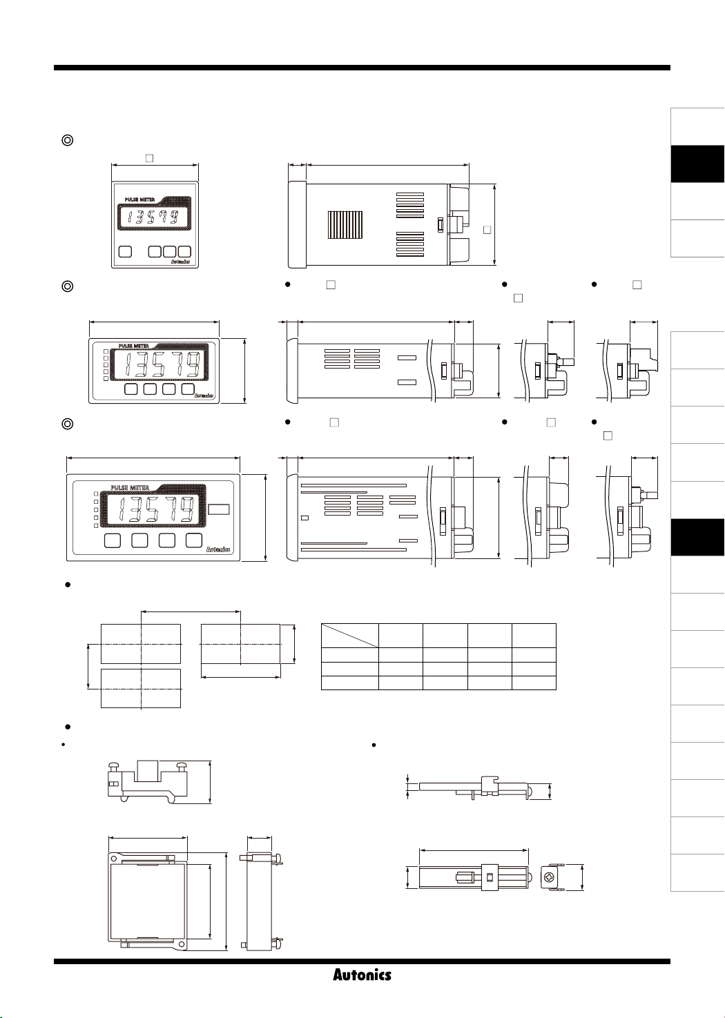
Dimensions
▣
※
Side dimensions of MP5Y/W dier by output type.
MP5S Series
48
Pulse Meter
(unit: mm)
SENSORS
9010
45
CONTROLLERS
MOTION DEVICES
SOFTWARE
MP5Y Series
MP5Y- N MP5Y
6
89.5
36
MP5W Series
96
MP5W- N MP5W- A/1
6
89.5
48
Panel cut-out
A
Size
Series
D
B
C
MP5S Min. 55 Min. 62 45.5
MP5Y Min. 91 Min. 40 68
MP5W Min. 116 Min. 52 92
Bracket
For MP5S For MP5Y/W
A B C D
10.5
10.5
+0.5
0
+0.7
0
+0.8
0
- 1/2/3/4/5
30
45
(unit: mm)
45.5
31.5
+0.6
45
0
MP5Y- 6
15.314.572
(J)
Temperature
Controllers
(K)
SSRs
14.5
(L)
Power
Controllers
(M)
Counters
(N)
Timers
(O)
Digital
Panel Meters
(P)
Indicators
(Q)
Converters
(R)
Digital
Display Units
(S)
Sensor
Controllers
(T)
Switching
Mode Power
Supplies
(U)
Recorders
MP5W
- 2/4/5/8/9
10.5
+0.5
0
+0.5
0
26.3
48.3 15
60.2
□45.8
4.4
12
10
73
14.5
(V)
HMIs
(W)
Panel PC
(X)
Field Network
Devices
O-81
Page 7

MP5S/MP5Y/MP5W Series
-|Transparent setting guide|-
▣ Unit Description
MP5S Series
MP5S Series
4
MP5S Series
4
1
2 3
1: Display component
Displays current value in RUN mode.
Alternately displays setting parameters and corresponding value in SETTING mode.
2:
key
In RUN mode, press the key once to check max./min. value.
In RUN mode, hold the key for over 2 sec to enter parameter groups.
3:
, , key
Select parameter groups, and select or setting values in the corresponding parameters.
4: Output status indicator
Sold Separately
▣
2
3
1
Communication converter
SCM-WF48
( Wi-Fi to RS485·USB wireless
communication converter)
SCM-US48I
(USB to RS485 converter)
Display Units (DS/DA-T Series)
DS/DA-T Series
(RS485 communication input type display unit)
2
3
SCM-38I
(RS232C to RS485 converter)
1
DS16- T DS22/DA22- T DS40/DA40- T DS60/DA60- T
※
Connect RS485 communication input type display unit (DS/DA-T Series) and RS485 communication output model of MP5Y/MP5W Series,
the display unit displays present value of the device without PC/PLC.
▣ Input Specications
1. Input signal
Standard duty ratio of input signal is 1:1.
(1) Solid state input 1
Input frequency: Max. 50kHz (ON/OFF pulse width: min. 10㎲ of each)
(2) Solid state input 2
Input frequency: Max. 5kHz (ON/OFF pulse width: min. 100㎲ of each)
※
For F7, F8, F9, F10 operation mode, max. 1kHz (ON/OFF pulse width: min. 500㎲ of each)
(3) Contact input
Input frequency: Max. 45Hz (when each ON/OFF pulse width is over 11ms)
①
Contact specications: 12VDC, stable switching of load current as small as 5mA
②
2. Input type [
MP5 allows selection between NPN input (solid state/contact) or PNP input (solid state/contact).
(1) NPN input type (2) PNP input type
Contact
①
IN-A, IN-B
NPN voltage
②
output type sensor
Sensor circuit
]
NPN open collector
③
output type sensor
+12V
(COM)
Sensor circuit
IN
0V
O-82
3.9kΩ
MP5
Sensor circuit
Contact② PNP voltage
①
output type sensor
Sensor circuit
ON
OFF
※
PNP open collector
③
output type sensor
Sensor circuit
Pulse width
OFF
ON
T
T: single cycle of input signal
+12V
IN
0V
(COM)
MP5
3.9kΩ
Sensor circuit
Page 8
-|Transparent setting guide|-
▣ Output Specications
1. Relay output
Output: Comparative or alarm output (refer to "
①
Output type: Relay
②
Contact capacity: 250VAC 3A resistive load
③
Life cycle: [Mechanical] min. 10,000,000 operations (switching frequency 180 operations/min)
④
[Electrical] min. 100,000 operations (3A 250VAC, 30VDC resistive load) (switching frequency 20 operations/min)
2. Transistor output
Output: Comparative output or alarm output (refer to "
①
Output type: NPN/PNP open collector
②
Rated load voltage: 30VDC
③
Max. load current: 30mA
④
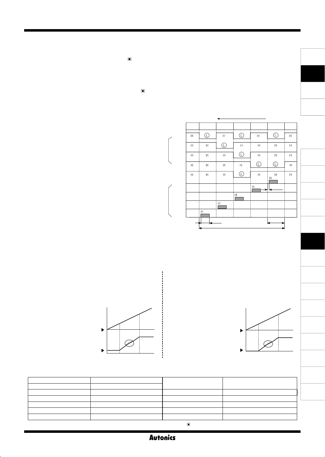
3. BCD dynamic output (negative logic)
Output: present value
①
Output signal: BCD data (A, B, C, D, DOT)
②
← A: lowest bit, DOT: highest bit
Digit data (D0, D1, D2, D3, D4)
← D0: lowest digit, D4: highest digit
Output type: NPN open collector
③
Rated load voltage: 30VDC
④
Max. load current: 30mA
⑤
Dynamic COM cycle (T) = 40ms
⑥
4. PV transmission output
Application: transmit measured value
①
Function: transmit measured value within setting range of high-limit output [
②
Output range of high/low-limit
③
·
·
(1) DC4-20mA transmission output
Transmit measured value within setting range of high-limit
①
output [
into DC4-20mA current.
Resistive load: Max. 500Ω
②
Resolution: 8000 divisions
③
If the setting width between [
[
FS-H
DC4-20mA or DC0-20mA current.
High-limit [
Low-limit [
] is lower than 8000 divisions, the
FS-H
] range: From min. value to max. value within measurement range
FS-L
] range: From min. value to max. value within measurement range ([
FS-H
] to low-limit output [
Set [
] and [
FS-L
the output is DC4-20mA.
FS-H
FS-L
] and
] and
resolution is also reduced.
FS-L
FS-L
4mA
Output Modes")
] after conversion
Diplay value
FS-H
20mA
Output Modes")
E.g.) To display value = 125.89 by BCD dynamic output
PV display value
BCD
Data
Digit
(2) DC0-20mA transmission output
①
②
③
If the setting width between [
[
A
B
C
D
DOT
D0
D1
D2
D3
D4
FS-H
] to low-limit output [
Transmit measured value within setting range of high-limit
FS-H
output [
DC0-20mA current.
Resistive load: Max. 500Ω
Resolution: 10,000 divisions
Set [
] is lower than 10,000 divisions,
FS-H
the resolution is also reduced.
Pulse Meter
4
-digit 100-digit
10
1 2 5. 8 9
5ms
FS-H
FS-L
]≥[
] to low-limit output [
] and [
FS-L
the output is DC0-20mA.
FS-H
FS-L
40ms
FS-L
] after conversion into
]+1)
FS-L
] and
] and
0mA
] after conversion into
FS-L
0.1ms
8ms
Display value
FS-H
20mA
SENSORS
CONTROLLERS
MOTION DEVICES
SOFTWARE
(J)
Temperature
Controllers
(K)
SSRs
(L)
Power
Controllers
(M)
Counters
(N)
Timers
(O)
Digital
Panel Meters
(P)
Indicators
(Q)
Converters
(R)
Digital
Display Units
(S)
Sensor
Controllers
(T)
Switching
Mode Power
Supplies
(U)
Recorders
(V)
HMIs
5. RS485 communication output
Comm. protocol Modbus RTU
Connection type RS485
Application standard Compliance with EIA RS485 Communication response time 5 to 99ms (default: 20ms)
Max. connection 31 units (address: 01 to 99) Start Bit 1-bit xed
Synchronous method Asynchronous Data Bit 8-bit xed
Comm. method Two-wire half duplex Parity Bit None (default), Even, Odd
Comm. distance Max. 800m Stop Bit 1, 2-bit (default)
※
For more information about RS485 communication output specications, refer to '
Communication Speed
RS485 Communication Output'.
2400, 4800, 9600 (default), 19200,
38400 bps
O-83
(W)
Panel PC
(X)
Field Network
Devices
Page 9
MP5S/MP5Y/MP5W Series
-|Transparent setting guide|-
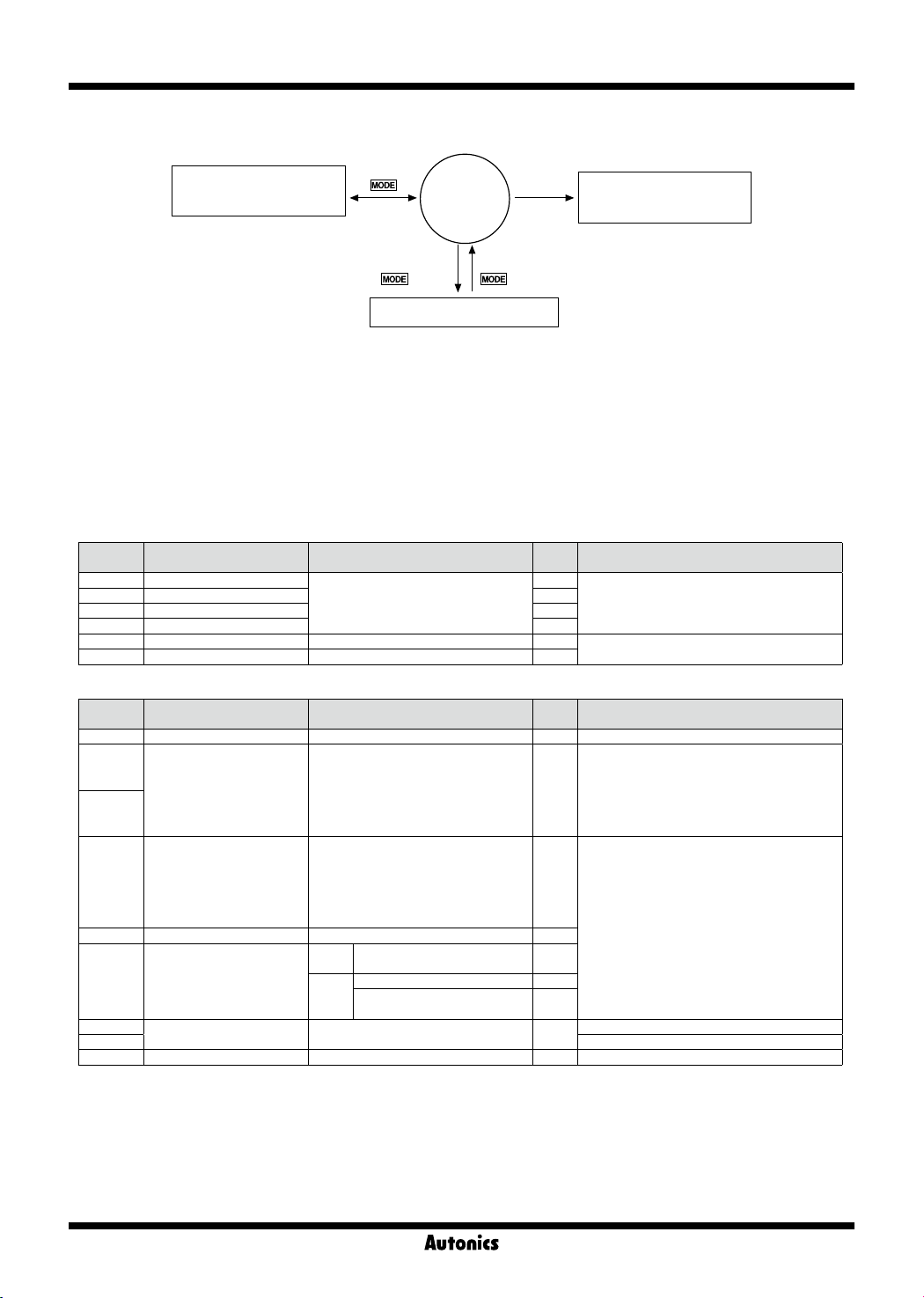
▣ Parameter Groups
Parameter 0 group
(max./min. monitoring value)
RUN
mode
HOLD/RESET
※1
Operation mode F1 to F12
Input
※1
: display value HOLD
Operation mode F13 to F16
2 sec 3 sec
Parameter 1/2/3 group
※
Press the ᜱ, ᜳ, ᜴ keys to
2
※2
: display value RESET
move the parameter group
• Press the ᜱ, ᜳ, ᜴ keys to select or set the desired value.
• Press the ᜮ key once after changing the setting value, to save the setting value and move to the next parameter.
• Hold the ᜮ key for 1.5 sec at any parameters to return to the select parameter group mode.
• Hold the ᜮ key for 3 sec to save the setting value and return to RUN mode after changing the setting value.
• If there is no key input for 60 sec while setting the parameters, the new settings are ignored, and the unit will return to RUN mode with
previous settings.
※
Each parameter and corresponding setting value will ash alternately every 0.5 sec.
※
Input operation mode setting range for each parameter is dierent.
Please refer to ‘▣ Operation Mode by Parameter Groups’.
● Parameter 0 group
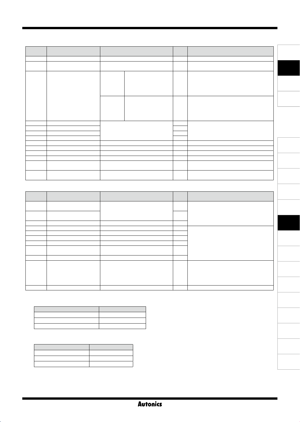
Parameter Description Setting range
PStHH
HH comparative value
PSt H
H comparative value
PSt L
L comparative value
PStLL
LL comparative value
hPEK
Max. monitoring value
lPEK
Min. monitoring value
● Parameter 1 group [
Parameter Description Setting range
MODE
Operation mode
IN-A
Input sensor type
IN-B
OUT-T
Output mode
HYS
Output hysteresis
GUARD
Delay monitoring
AUToA
Auto-zero time (unit: sec)
AUToB
MEMO
Memory retention
※
PARa1
※
3
※
1
The setting range varies depending on
the operation mode
1
-
-
]
F1
F16 F1
to
NPnhF
: NPN solid state input 1
NPnmF
: NPN solid state input 2
NPnlF
: NPN contact input
PNphF
: PNP solid state input 1
PNpmF
: PNP solid state input 2
PNplF
: PNP contact input
STARD
: S (Standard)
OUT-H
: H (High)
OUT-L
: L (Low)
OUT-B
: B (Block)
OUT-I
: I (One-shot)
OUT-F
: F (Deection)
0000
9999 0001
to
LL, L Comparative output limit
fDEFY
function
Start compensation timer function
STArT
Compensation time
()0 to
)1
999(9 999(9
to
OFF, ON OFF
9(9
※
2
sec)
Factory
Note
default
99999
- The parameters are linked to the parameter 2
99999
group
- Only appears in comparative value setting
00000
models
00000
99999
Reset(current value):
Hold ᜱkey over 2 sec
`9999
Factory
Note
default
NPnhF
STARD
Does not appear in indicator models
-
-
)0
Input A
Input B
O-84
Page 10
Pulse Meter
-|Transparent setting guide|-
● Parameter 2 group [
PARa2
]
Parameter Description Setting range
pBANK
Data bank
Decimal point location of
DOT
display value
tUNT
Tim unit, time range
PStHH
HH comparative value
PSt H
H comparative value
PSt L
L comparative value
PStLL
LL comparative value
PScaH
Input A prescale mantissa (x)
PScaY
Input A prescale exponent (y)
PScbH
Input B prescale mantissa (x)
PScbY
Input B prescale exponent (y)
Measured value display cycle
DISpT
(unit: sec)
Input B setting value of
COUnB
operation mode F16 (INB)
※
4
● Parameter 3 group [
PARa3
1, 2 1
00000, 000)0, 00)00, 0)000, )0000 00000
99(99
: 999.99s
999(9
tSEC
(sec)
tMIN
(min)
※
1
The setting range varies depending on
the operation mode
※
1
)0001
10 - 9
)0001
10 - 9
(9999 ^0000
to
-9
) to
(10
(9999 ^0000
to
-9
) to
(10
9(5(9
(5(59
99999
99(99
999(9
9(5(9
(5(59
99999
10 09
10 09
: 9999.9s
: 99m 59.9s
: 9h 59m 59s
: 99999s
: 999.99m
: 9999.9m
: 99h 59.9m
: 999h 59m
: 99999m
※
2
(109)
(109)
)05, )5, 1, 2, 4, 8 )05
1
99999 99999
to
]
Parameter Description Setting range
Upper limit value of PV
FS-H
transmission output
Lower limit value of PV
FS-L
transmission output
MA
Current output specication
ADDR
Comm. address
BPS
Comm. speed (unit: bps)
PRTY
Comm. parity bit
STP
Comm. stop bit
RSwT
Comm. response wait time
COmW
Comm. write enable/disable
LOC
Lock
mRST
Parameter reset
※
1: Does not appear in F output mode.
※
2: Setting range by operation mode varies depending on the decimal point setting.
The setting range varies depending on
the operation mode
※
2
4-20, 0-20 4-20
01
99 01
to
2400, 4800, 9600, 19200, 38400 9600
NONE, EVEN, ODD NONE
1, 2 2
The setting range varies depending on
the comm. speed
ENA
(Enable),
OFF
LOc0
LOc1
LOc2
LOc3
ENA
(Enable),
※
5
DISA
(Disable)
: Unlock
: Lock all
: Parameter 1/2/3 lock
: Parameter 2/3 lock
: Parameter 3 lock
DISA
(Disable)
Operation mode Setting range
F1, F2, F7, F9, F11, F12, F13, F160 to
F3, F4, F5, F6
F8, F10, F14, F15
※
3: The setting range varies depending on the decimal point setting.
※
4: Setting range
※
5: Setting range by communication speed
OFF
is available in operation mode F2, F16.
99999
)01
to setting time range
`9999
to
99999
Comm. speed (unit: bps) Setting range (unit: ms)
16
2400
4800
9600, 19200, 38400
99
to
8
99
to
5
99
to
Factory
Note
default
Only appear in MP5W
99(99
99(99
99999
- The parameters are linked to the parameter 0
99999
group
- Only appears in comparative value setting
00000
models
00000
10 01
10 01
Only appears in operation mode F16
Factory
Note
default
99999
Only appears in PV transmission output models
00000
Only appears in RS485 comm. output models
20
DISA
OFF
ENA
SENSORS
CONTROLLERS
MOTION DEVICES
SOFTWARE
(J)
Temperature
Controllers
(K)
SSRs
(L)
Power
Controllers
(M)
Counters
(N)
Timers
(O)
Digital
Panel Meters
(P)
Indicators
(Q)
Converters
(R)
Digital
Display Units
(S)
Sensor
Controllers
(T)
Switching
Mode Power
Supplies
(U)
Recorders
(V)
HMIs
(W)
Panel PC
(X)
Field Network
Devices
O-85
Page 11
MP5S/MP5Y/MP5W Series
-|Transparent setting guide|-
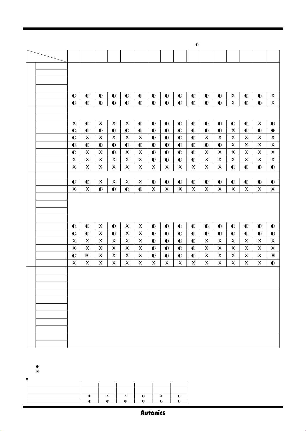
▣ Operation Mode by Parameter Groups
Operation
mode
Parameter
PStHH
PSt H
PSt L
PSt LL
0 group
hPEK
lPEK
MODE
IN-A
IN-B
OUT-T
HYS
1 group
GVARD
AVToA
AVToB
MEMO
pBANK
DOT
tUNT
PStHH
PSt H
PStLL
PSt L
2 group
PScaH
PScaY
PScbH
PScbY
DISpT
COUnB
FS-H
FS-L
ADDR
BPS
PRTY
3 group
STP
REwT
COmW
mRST
※
1: Only appears in only for quintuple output models.
※
2: Only appears in triple, quintuple output models.
※
3: The settings for
※
4: (
) F output mode [
※
5: ( ) setting range:
Monitoring delay function by output mode
Output mode S mode H mode L mode B mode I mode F mode
Parameter
Comparative output limit
Start compensation timer
F1 F2 F3 F4 F5 F6 F7 F8 F9 F10 F11 F12 F13 F14 F15 F16
※
1
※
2
※
2
※
1
Appears in all operation modes (F1 to F16).
Appears in all operation mode (F1 to F16).
※
2
※
2
※
2
※
ppears in MP5W. Appears in all operation modes (F1 to F16).
Only a
※
1
※
2
※
2
※
1
※
5
Appears in all operation modes (F1 to F16).
※
Only appears in PV transmission output models.
Appears in operation modes (F1 to F16).
ㅡMA
※
Only appears in RS485 comm. output models.
Appears in all operation modes (F1 to F16).
LOC
IN-B
and
OUT-F
IN-A
are applied.
] cannot be set.
Appears in all operation modes (F1 to F16).
OFF, )05, )5, 1, 2, 4, 8
STARD OVT-; OVT-L OVT-B OVT-I OVT-F
( : parameter display, X: no parameter display)
※
3
※
4
O-86
Page 12
Pulse Meter
-|Transparent setting guide|-
Operation Modes [
▣
Select operation mode from operation mode[
MODE
]
MODE
]of parameter 1 group..
MP5 has 16 operation modes.
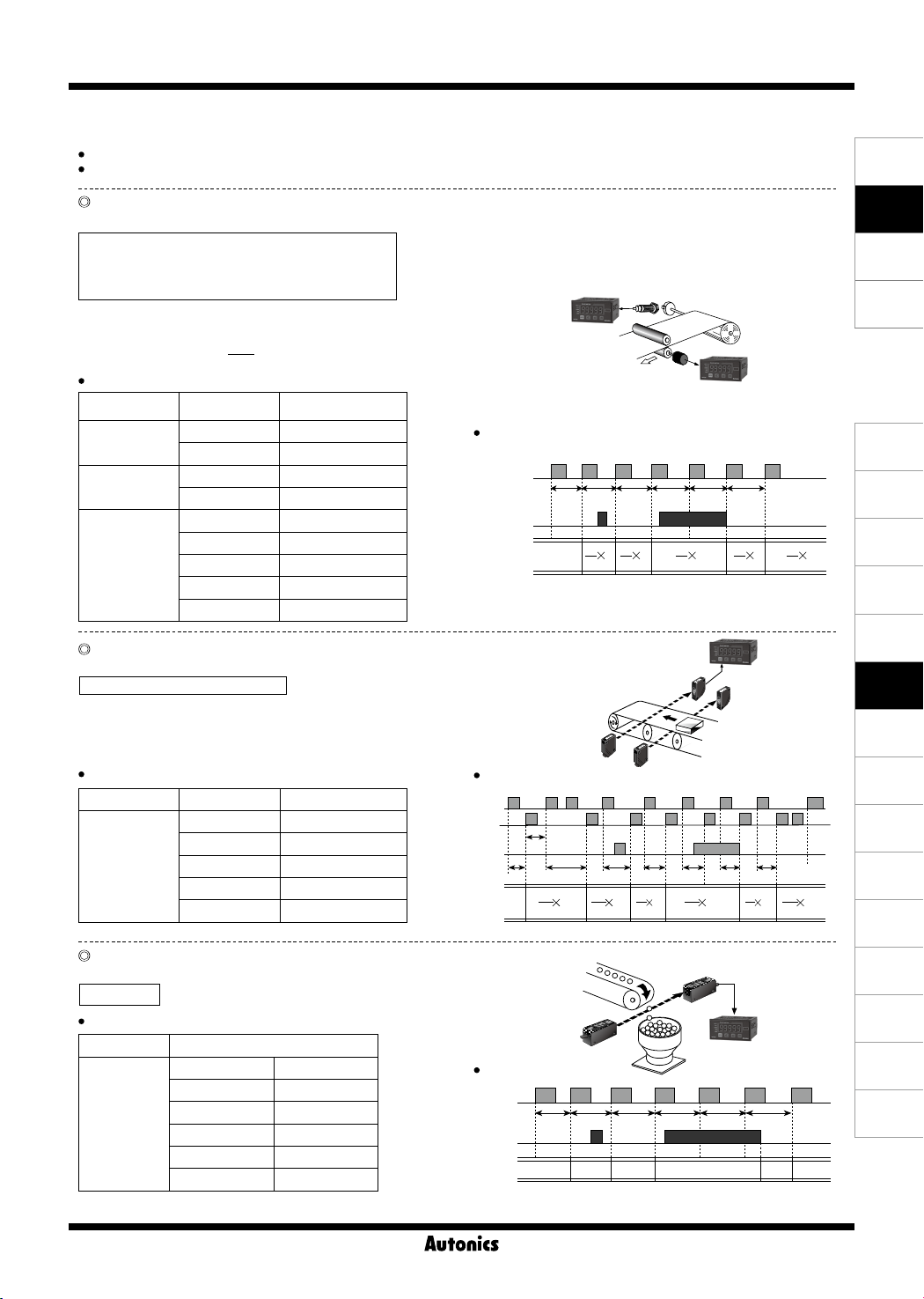
F1 Mode: Frequency/Revolutions/Speed
Measures the frequency of input A and displays the calculated frequency, revolutions, and speed.
1) Frequency (Hz) = f × α (α= 1 [sec])
2) Revolutions (rpm) = f × α (α= 60 [sec])
3) Speed (m/min) = f × α (α= 60L [sec])
※
L: travel distance of conveyor belt of 1 pulse cycle[m]
α: prescale value
For multiple objects, α =
N
60L
MP5
Display value and display unit
Display value Display unit α (prescale value)
Frequency
Revolutions
Speed
Hz 1
kHz 0.001
rps 1
rpm (default) 60
mm/sec 1,000L
cm/sec 100L
m/sec 1L
Timing chart
Input A
Hold
input
Display
t1 t2 t3 t4 t5 t6
1
t1
m/min 60L
km/hour 3.6L
F2 Mode: Passing Speed
Displays the passing speed between input A ON and input B ON.
Passing speed (V) = f × α (α = L[m])
※
f : reciprocal of time [sec] between input A (sensor) ON and
input B (sensor) ON.
L: distance between input A (sensor) and input B (sensor) [m]
α: prescale value
Display value and display unit
Display value Display unit α (prescale value)
mm/sec 1,000L
cm/sec 100L
Passing speed
m/sec (default) 1L
m/min 60L
km/hour 3.6L
Timing chart
Input A
Input B
Hold
input
Display
※
Return time (over 20ms)
ta:
Sensor B
ta
t1
t2 t3 t4 t5 t6 t7
1
1
α
t1
t 2
F3 Mode: Cycle
Displays the measured time from Input A ON to the next ON.
Cycle (T) = t ※t: measurement time [sec]
Display value and display unit ([
Display value Display unit
Sec Min
999.99s (default) 999.99m
Cycle
9999.9s 9999.9m
99m 59.9s 99h 59.9m
9h 59m 59s 999h 59m
99999s 99999m
tUNT
] of parameter 2)
Photoelectric
Timing chart
Input A
Hold
input
Display
sensor
t1
t2
t1 t2
Encoder
MP5
1
α
t 2
1
α
α
t 3
MP5
Sensor A
α
t3
α
t4
1
1
α
t3 t4 t5 t6
t3 t5 t6
MP5
SENSORS
CONTROLLERS
MOTION DEVICES
SOFTWARE
(J)
Temperature
Controllers
(K)
SSRs
(L)
1
t5
1
α
t6
1
1
α
t6
α
t7
Power
Controllers
α
(M)
Counters
(N)
Timers
(O)
Digital
Panel Meters
(P)
Indicators
(Q)
Converters
(R)
Digital
Display Units
(S)
Sensor
Controllers
(T)
Switching
Mode Power
Supplies
(U)
Recorders
(V)
HMIs
(W)
Panel PC
(X)
Field Network
Devices
O-87
Page 13
MP5S/MP5Y/MP5W Series
-|Transparent setting guide|-
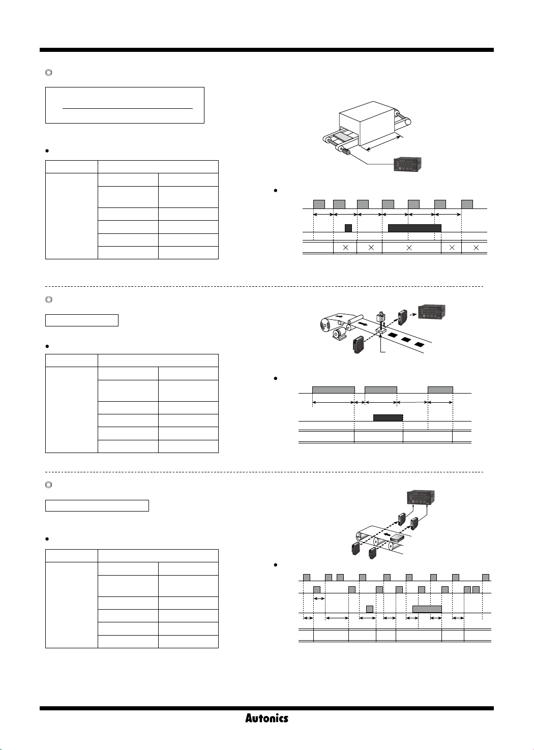
F4 Mode: Passing Time
Measures the time from Input A ON to the next ON, and displays the passing time of the arbitrary distance.
Passing time[sec]= t × α
L[m]
(α=
Distance advanced in 1 pulse cycle [m]
※
t : measured time[sec], L : arbitrary distance[m]
α: prescale value
Display value and display unit ([
Display value Display unit
SEC MIN
Passing time
999.99s
(default)
9999.9s 9999.9m
99m 59.9s 99h 59.9m
9h 59m 59s 999h 59m
99999s 99999m
999.99m
F5 Mode: Time Interval
Displays measured time of Input A ON
Time interval (T) = t
※
t: measured time of input A ON [sec]
Display value and display unit ([
Display value Display unit
SEC MIN
Time interval
999.99s
(default)
9999.9s 9999.9m
99m 59.9s 99h 59.9m
9h 59m 59s 999h 59m
99999s 99999m
999.99m
)
tUNT
] of parameter 2)
tUNT
] of parameter 2)
Timing chart
Input A
Hold
input
Display
Motor
Timing chart
Input A
Hold
input
Display
※
Return time (over 20ms)
ta:
t1
t2
αt2α
t1
t1
L : Length[m]
t3 t4 t5 t6
Stamp
t2 t3
t1 t2
MP5
α
t3
MP5
tata
α
t5
α
t6
t3
F6 Mode: Time Dierentia
Displays measured time from Input A ON to Input B ON.
Time dierential (T) = t (ta to tb)
※
t (ta to tb): measured time from input A ON to input B ON [sec]
Display value and display unit ([
Display value Display unit
SEC MIN
999.99s
(default)
Time
dierence
9999.9s 9999.9m
99m 59.9s 99h 59.9m
9h 59m 59s 999h 59m
99999s 99999m
l
tUNT
999.99m
O-88
] of parameter 2)
Timing chart
Input A
Input B
Hold
input
t1 t3 t5 t6 t7
Display
※
Return time (over 20ms)
ta:
MP5
Sensor B
Sensor A
ta
t4t2
t1 t2 t3 t4 t6 t7
Page 14
-|Transparent setting guide|-
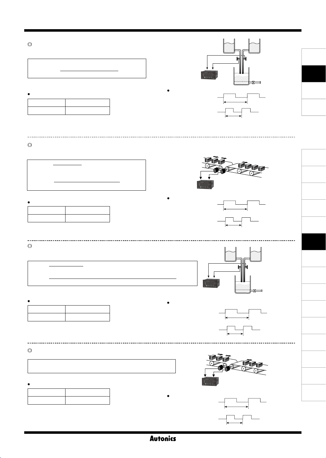
F7 Mode: Absolute Ratio
Measures and displays relative speed, amount, speed, etc.
of input B against input A in percentage (%).
Absolute ratio = (Input B / Input A) × 100%
Absolute ratio =
Frequency of input A[Hz] × Aα
※
Aα: Prescale value of input A, Bα: Prescale value of input B
Display value and display unit
Frequency of input B[Hz] × Bα
× 100[%]
Timing chart
Display value Display unit
Absolute ratio %
※
Hold: When the hold signal turns ON, the display value is
maintained until the display cycle turns to hold OFF.
Frequency of input B[Hz] × Bα
Display =
Frequency of input A[Hz] × Aα
F8 Mode: Error Ratio
Measures and displays the relative rate of input B against the reference value of input A
in percentage (%).
Error ratio =
Input A
Input B-Input A
× 100[%]
(Frequency of input B [Hz] × Bα)
Error ratio =
※
Aα: prescale value of input A, Bα: prescale value of input B
Display value and display unit
- (Frequency of input A[Hz] × Aα)
Frequency of input A[Hz] × Aα
× 100[%]
Timing chart
Display value Display unit
Error ratio %
※
Hold: When the hold signal turns ON, the display value is
maintained until the display cycle turns to hold OFF.
F9 Mode: Density
Measures and displays the density ratio (%) of input B against the total sum of input A
and input B.
Density =
Density =
※
Display value and display unit
Input B
Input A + Input B
× 100[%]
Frequency of Input B[Hz] × Bα
(Frequency of input A[Hz] × Aα) + (Frequency of input B[Hz] × Bα)
Aα: Prescale value of input A, Bα: Prescale value of input B
× 100[%]
Timing chart
Display value Display unit
Density %
※
Hold: When the hold signal turns ON, the display value is
maintained until the display cycle turns to hold OFF.
F10 Mode: Error
Measures and displays the error of input B against reference value of input A.
Error = Input B - Input A
Error = (Frequency of input B[Hz] × Bα) - (Frequency of input A[Hz] × Aα)
※
Aα: prescale value of input A, Bα: prescale value of input B
Display value and display unit
Display value Display unit
Error END User setting
※
Hold: When the hold signal turns ON, the display value is
maintained until the display cycle turns to hold OFF.
Timing chart
Flow meter
Input
Input
Input A
Input B
Flow meter
MP5
Input A
Input B
MP5
Input A
Input B
MP5
A
B
Conveyor
MP5
Conveyor
Pulse Meter
A
fA
fB
A
fA
fB
A
fB
fB
Liquid
Liquid
fA
A
Conveyor
fA
Flow meter
× 100[%]
Conveyor
Flow meter
B
B
B
B
SENSORS
CONTROLLERS
MOTION DEVICES
SOFTWARE
(J)
Temperature
Controllers
(K)
SSRs
(L)
Power
Controllers
(M)
Counters
(N)
Timers
(O)
Digital
Panel Meters
(P)
Indicators
(Q)
Converters
(R)
Digital
Display Units
(S)
Sensor
Controllers
(T)
Switching
Mode Power
Supplies
(U)
Recorders
(V)
HMIs
(W)
Panel PC
(X)
Field Network
Devices
O-89
Page 15
MP5S/MP5Y/MP5W Series
-|Transparent setting guide|-
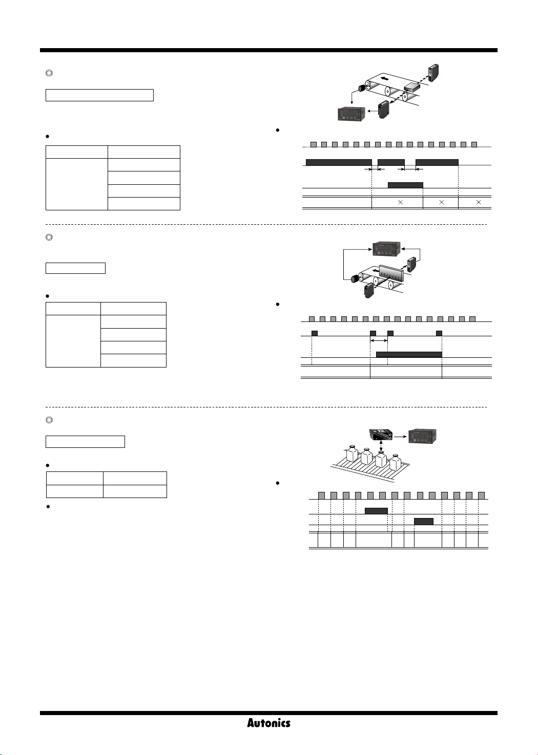
F11 Mode: Length Measurement 1
Measure and display the number of input A pulses during input B ON.
Length measurement = P × α
※
P: Number of input A pulses, α: Prescale value
Display value and display unit
Display value Display unit
Quantity (default)
Length
measurement
mm
cm
m
Input A
Timing chart
Input A
Input B
Display
1 5 2 33 12 6
Hold
input
※
ta, tb: return time (over 20ms)
MP5
Input B
ta
Photoelectric sensor
tb
α 2 α 4 α
6
44 1 2
F12 Mode: Interval
Measures and displays the number of input A pulses from Input B
ON to the next ON.
Interval = P × α
※
P: Number of input A pulses, α: Prescale value
Display value and display unit
Display value Display unit
Quantity (default)
Interval
mm
cm
m
F13 Mode: Accumulation
Measures and displays the counted value of input A pulses.
Accumulation = P × α
※
P: Number of input A pulses, α: Prescale value
Display value and display unit
Display value Display unit
Accumulation Quantity[EA]
Operation
Counts the number of input A pulses.
①
Input B is an enable input signal. During ON, the quantity and
②
display value of input A will be held, and during OFF input A will
be re-counted.
When RESET input is ON, the integrated counted value will be reset
③
to "0".
MP5
Timing chart
Input A
Input B
Hold
input
Display
※
return time (over 20ms)
ta:
1 1 153 3 32 2 24 4
Photoelectric sensor
ta
5×α 4×α
MP5
Timing chart
Input A
Input B
RESET
Display10 01 12 23 34 4
※
α=1 display value
5
5
6
33 12 6
44 2
O-90
Page 16
-|Transparent setting guide|-
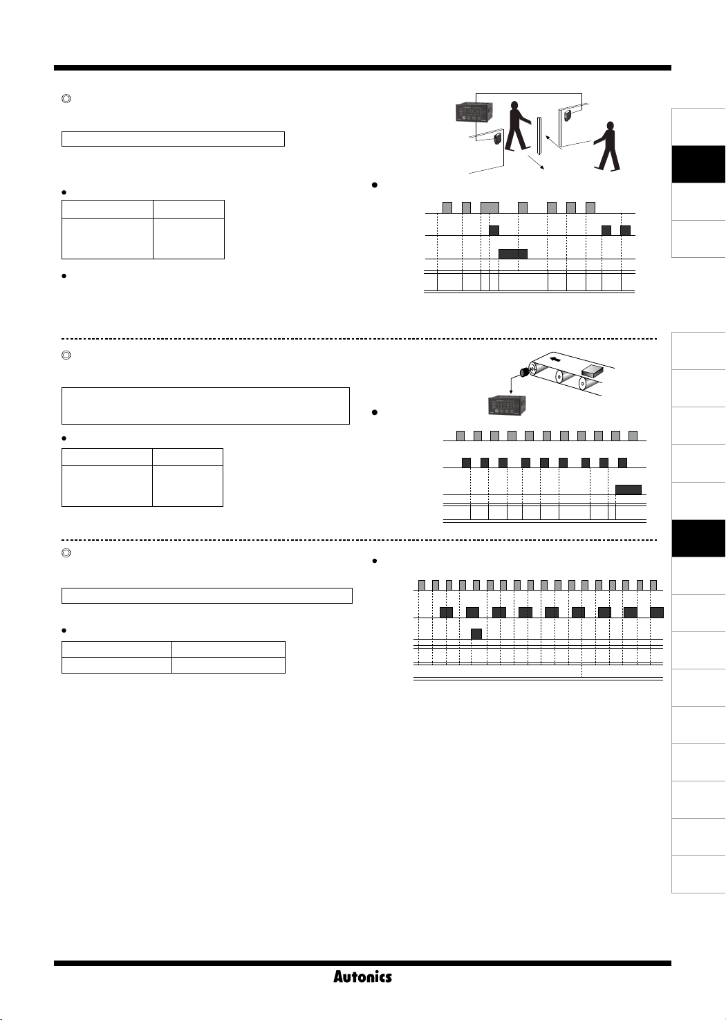
F14 Mode: Addition/Subtraction-Individual Input
Displays the counted value from added input A pulses and subtracted
input B pulses. When there are two inputs simultaneously, it will not count.
Addition/Subtraction = Input A × α - Input B × α
※
α: Prescale value of input A
Display value and display unit
Display value Display unit
Addition/
Subtraction
Quantity
(individual input)
Operation and timing chart
Pulse of input A is added, and pulse of input B is subtracted.
F15 Mode: Addition/Subtraction- Phase dierence input
When input A is low, counting is added to the low of input B.
When input A is low, counting is subtracted from the high of input B.
Addition/Subtraction (phase dierence)
= Detects position and speed using A and B phases of
encoder outputs as input.
Display value and display unit
Display value Display unit
Up/Down counting
(phase dierence
Quantity
input)
F16 Mode: Length Measurement 2
Measures and displays the number of pulses from input A until the value
of input B reaches the set value.
Length measurement 2 = P × α (until the setting value of Input B)
※
P: Number of input A pulses, α: Prescale value
Display value and display unit
Display value Display unit
Length measurement 2 Quantity[EA]
※
If input A and input B are ON during initial power supply, it will not
count and only count the number of rising edge.
※
Display value is renewed depending on the display cycle [
setting.
DISpT
]
Pulse Meter
MP5
Timing chart
Input A
Input B
RESET
H
L
H
L
H
L
Display
※
Photoelectric
sensor
0 01 2 2 2 23 1 13
α=1 display value
Input A
(addition)
Input A
Input B
Timing chart
H
Input A
Input B
RESET
Timing chart (e.g.) setting value of Input B=4
Input A
Input B
RESET
Display
Display
※
1: When the display cycle [
L
H
L
H
L
Display
H
L
H
L
H
L
※
1
0 01 1 12 2 23 0
1 2 41
1
2
3
1
2 10
0
DISpT
the quantity of input A until the value of input B reaches the
setting value B [
COUnB
].
Input B
(subtraction)
MP5
3 32 2
3
6
] setting is
7
OFF
1
24 4 30 5 4 5
7
, it will maintain
SENSORS
CONTROLLERS
MOTION DEVICES
SOFTWARE
(J)
Temperature
Controllers
(K)
SSRs
(L)
Power
Controllers
(M)
Counters
(N)
Timers
(O)
Digital
Panel Meters
(P)
Indicators
(Q)
Converters
(R)
Digital
Display Units
(S)
Sensor
Controllers
(T)
Switching
Mode Power
Supplies
O-91
(U)
Recorders
(V)
HMIs
(W)
Panel PC
(X)
Field Network
Devices
Page 17
MP5S/MP5Y/MP5W Series
-|Transparent setting guide|-
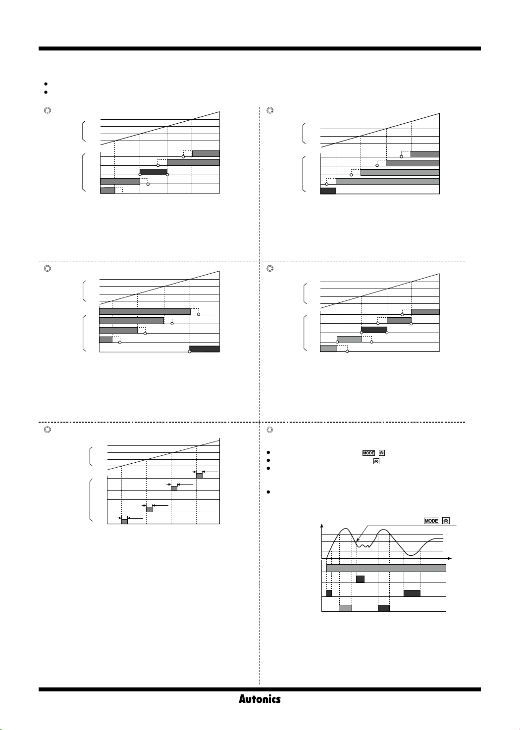
▣ Output Modes [
OUT-T
]
MP5 Series supports 6 output modes. (There is no output mode in indicator models).
Requirement for setting comparative value: (B output mode) LL<L<H<HH, (F output mode) L<H,
(other output modes) individual output operation regardless of size or order of set comparative values.
1
STARD
] H (high) Output Mode [
Comparative
value
※
1
※
1
※
1
Output
HH output : Display value ≥ Comparative setting value HH
H output : Display value ≥ Comparative setting value H
L output : Display value ≥ Comparative setting value L
LL output : Display value ≥ Comparative setting value LL
1:
※
GO output ON when there are no HH, H, L, LL outputs
OUT-L
] B (block) Output Mode [
Comparative
value
※
※
※
1
1
1
Output
HH output : Display value ≥ Comparative setting value HH
H output : Comparative setting value HH > Display value ≥
L output : Comparative setting value LL < Display value ≤
HH
H
L
LL
HH
GO
HH
HH
GO
H
L
LL
H
L
LL
H
L
LL
※
※
1
※
1
Comparative setting value H
Comparative setting value L
S (standard) Output Mode [
HH
HH
GO
H
L
LL
H
L
※
LL
Comparative
value
Output
HH output : Display value ≥ Comparative setting value HH
H output : Display value ≥ Comparative setting value H
L output : Display value ≤ Comparative setting value L
LL output : Display value ≤ Comparative setting value LL
1:
※
GO output ON when there are no HH, H, L, LL outputs
L (low) Output Mode [
Comparative
value
HH output : Display value ≤ Comparative setting value HH
H output : Display value ≤ Comparative setting value H
L output : Display value ≤ Comparative setting value L
LL output : Display value ≤ Comparative setting value LL
1:
※
HH
H
L
LL
HH
H
GO
L
※
1
LL
Output
GO output ON when there are no HH, H, L, LL outputs
LL output : Display value ≤ Comparative setting value LL
1:
※
GO output ON when there are no HH, H, L, LL outputs
0.3s
OUT-I
0.3s
]
0.3s
0.3s
F (deflection) Output Mode [
Transmits outputs when the saved setting value exceeds H
deviation or L deviation.
Saving setting value: press the +
Checking setting value: press the key to check the setting value.
Setting deviation: Sets H deviation [
L
] of parameter group 0,2 with the setting value as reference. (The
set deviation value is saved during Power OFF until it is re-set.)
Deviation setting range: 0.0001 to 99999 (the setting range varies
depending on the decimal point [
(high-limit)
(low-limit)
ON
OFF
ON
OFF
ON
OFF
ON
OFF
DOT
]: 0000.0, Setting range: 0.1 to 9999.9
※
2
※
3
E.g.) Decimal point[
H deviation
Setting value
L deviation
Power
Saving
setting value
L deviation
output
H deviation
output
※
2: When selecting initial comparative output limit function, it does
not transmit outputs.
※
3: The graph is assuming that there is a saved setting value prior
I (one-shot) Output Mode [
Comparative
value
HH output : Display value ≥ Comparative setting value HH
H output : Comparative setting value HH > Display value ≥
L output : Comparative setting value H > Display value ≥
LL output : Comparative setting value L > Display value ≥
※
No GO output
※
One-shot output time is fixed at 0.3 sec.
※
No hysteresis
HH
H
L
LL
HH
H
Ouput
GO
L
LL
Comparative setting value H
Comparative setting value L
Comparative setting value LL
to the setting value save point. The actual output position may
be different.
※
There are no HH, GO, LL outputs.
※
The deviation can be set to "0" but the actual operation will be the
same as "1".
OVT-H
]
※
1
※
1
1
OUT-B
]
※
1
※
1
※
1
OVT-F
]
keys to save as setting value.
PSt H
], and L deviation[
DOT
] setting.)
Saving setting value ( + key)
※
1: hysteresis
PSt
O-92
Page 18
Pulse Meter
-|Transparent setting guide|-
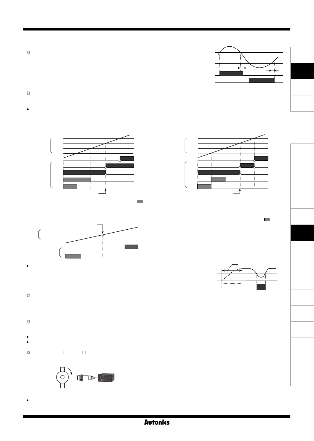
▣ Function
Hysteresis [
Near the comparative setting value, the output may turn ON/OFF
frequently and unstably.
To prevent this, hysteresis value is set based on the comparative
setting value.
※
A: hysteresis value
※
The hysteresis value can be set to "0" but the actual operation value is "1".
Delay monitoring [
HYS
]
GUArD
]
Comparative setting
H, HH
value
Comparative setting
L, LL
value
Output H, HH
Output L, LL
A
A
After supplying power, the starting current of motors and other inputs are changeable. This function allows stable control by limiting all outputs
for a certain period of time, until the target measurement unit stabilizes. It may also control L, LL outputs until a specific output is reached.
Comparative output limit function [
fDEFY
]
: Only for S (Standard), B (Block), F (Deflection) output mode.
: Limits L, LL output before H, HH output.
※
Initial L, LL outputs does not operate, so GO output operates.
1) During S (Standard) output mode 2) During B (Block) output mode
Output
HH
H
L
LL
HH
H
GO
L
LL
removal
HH
Comparative
value
H
L
LL
Comparative
value
HH
H
GO
Output
L
LL
Comparative output limit function
※
After supplying power, there is no initial L, LL comparative outputs (
※
Each setting value of HH, H, LL, L is not related to their relative sizes. Hence, HH value may be lower or equal to LL value.
removal
) .
Comparative output limit function
3) During F (Deflection) output mode
※
H deviation
Setting value
value
L deviation
Comparative
Output
Comparative output limit
function removal
H
After supplying power, there is no comparative output
deviation
※
.
In F output mode, the comparative output limiting function is
removed at the set value (standard setting)
※
H and L deviation are not related to their relative sizes.
(H deviation setting value > L deviation setting value,
H deviation setting value < L deviation setting value)
( )
of L
L
Start compensation timer function [
STArT
]
Set monitoring delay time so that there is no output during the delay time.
Auto-zero time setting [
AUToA, AUToB
]
L, LL
comparative
setting value
Output
Monitoring delay time
No output
When there is no input signal during auto-zero setting time, the display value is automatically set to 0 (zero). Please set the auto-zero setting
time so that it is longer than the interval of the slowest input signal. If the setting time is too long and there is no input signal, the rate at which
the display value falls to 0 (zero) decrease, and output response rate may slow down.
Data bank [
pBANK
] (only for MP5W)
Comparative setting value and prescale value are saved as two types (data bank 1, 2) and can be selected for use by opening or shorting of
terminals.
Terminal 3, 5 open: use value of data bank 1
Terminal 3, 5 short: use value of data bank 2
PSc
Prescale [
.H, PSc .Y
]
Displays values in required units or specific multiples by counting the number of input pulses, then multiplying the number of pulses or the
length of pulses by variables (X×10y).
Number of revolutions (rpm) = f×α
MP5
= f×60×(1 / N)
= f×60×(1 / 4)
= f×60×0.25
= f×15
※
f: The number of input pulses per second [Hz],
α: Prescale value
N: The number of pulses per revolution
Setting prescale value (α=15)
Set mantissa (X) as 1.5000, and exponent (Y) as 1 for prescale value (α)=15.
The same display value can be obtained with α value set as X=0.1500, and Y=2.
SENSORS
CONTROLLERS
MOTION DEVICES
SOFTWARE
(J)
Temperature
Controllers
(K)
SSRs
(L)
Power
Controllers
(M)
Counters
(N)
Timers
(O)
Digital
Panel Meters
(P)
Indicators
(Q)
Converters
(R)
Digital
Display Units
(S)
Sensor
Controllers
(T)
Switching
Mode Power
Supplies
(U)
Recorders
(V)
HMIs
(W)
Panel PC
(X)
Field Network
Devices
O-93
Page 19
MP5S/MP5Y/MP5W Series
-|Transparent setting guide|-
▣ RS485 Communication Output
Applicable for models with RS485 communication output through sub output (MP5Y- 5, MP5W- 8/9).
Please refer to '
1. Communication specications
Comm. protocol Modbus RTU
Connection type RS485
Application standard Compliance with EIA RS485 Communication response time 5 to 99ms (default: 20ms)
Max. connection 31 units (address: 01 to 99) Start Bit 1-bit xed
Synchronous method Asynchronous Data Bit 8-bit xed
Comm. method Two-wire half duplex Parity Bit None (default), Even, Odd
Comm. distance Max. 800m Stop Bit 1, 2-bit (default)
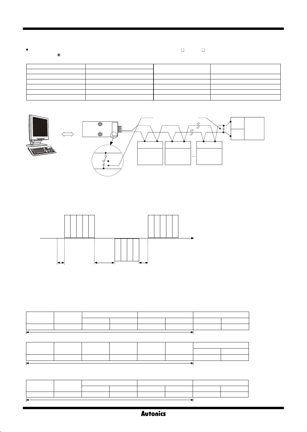
2. System conguration
Computer
※
It is recommended to use Autonics communication converter; SCM-WF48 (Wi-Fi to RS485·USB wireless communication converter, sold
separately), SCM-US48I (USB to RS485 converter, sold separately), SCM-38I (RS232C to RS485 converter, sold separately).
Please use twisted pair wire for RS485 communication.
3. Communication control sequence
1. Communication sequence follows Modbus RTU protocol.
2. Communication with the host system can be established after 1sec (1,000ms) of supplying power.
3. The initial transmission authority is held by the host device (PC). When the host device transmits a request, the MP5W/Y Series sends a
response.
Ordering Information'.
RS232C/
USB/Wi-Fi
Comm.
converter
ON
B(-)
A(+)
RS485
OFF
Communication Speed
Terminating resistance
(100 to 120Ω)
A(+) B(-) A(+) B(-) A(+) B(-)
RS485
DEVICE
#1
RS485
DEVICE
#2
2400, 4800, 9600 (default), 19200,
38400 bps
RS485
DEVICE
#30
B(-)
A(+)
RS485
DEVICE
#31
Host
system
MP5W/Y
Series
A
Address
Read command
4. Cautions for communication
1. Twisted pair cable (AWG24) is recommended for RS485 communication. When not using twisted pair cables, please make sure that A (+)
and B (-) cable lengths are equal.
2. After connecting the communication cable, terminating resisters (100 to 120Ω) must be attached at both ends.
Address
No. of data
CRC16
Address
B C
CRC16
No. of data
Response command
Address
Read command
※
A: after 1 sec of supplying
B: 38400bps: approx. 1.75ms
C: over 20ms
CRC16
Address
No. of data
power
19200bps: approx. 2ms
9600bps: approx. 4ms
4800bps: approx. 8ms
2400bps: approx.16ms
※
The longer of the communication
response wait time [
parameter group 3 and response time
of B is applied.
RSwT
] of
5. Communication command and block denition
5-1. Read coil status (func 01 H), read input status (func 02 H)
1) Query (Master)
Slave
Address
1Byte 1Byte 1Byte 1Byte 1Byte 1Byte 1Byte 1Byte
2) Response (slave)
Slave
Address
1Byte 1Byte 1Byte 1Byte 1Byte 1Byte 1Byte 1Byte
5-2. Read Holding registers (func 03 H), read input registers (func 04 H)
1) Query (Master)
Slave Address
1Byte 1Byte 1Byte 1Byte 1Byte 1Byte 1Byte 1Byte
Function
(command)
Function
(command)
Function
(command)
Starting Address No. of Points (no. of data) Error Check (CRC 16)
High Low High Low Low High
CRC16
Byte Count
(no. of data byte)
Starting Address No. of Points (no. of data) Error Check (CRC 16)
High Low High Low Low High
Data (low) Data Data (high)
CRC16
CRC16
Error Check (CRC 16)
Low High
O-94
Page 20
Pulse Meter
-|Transparent setting guide|-
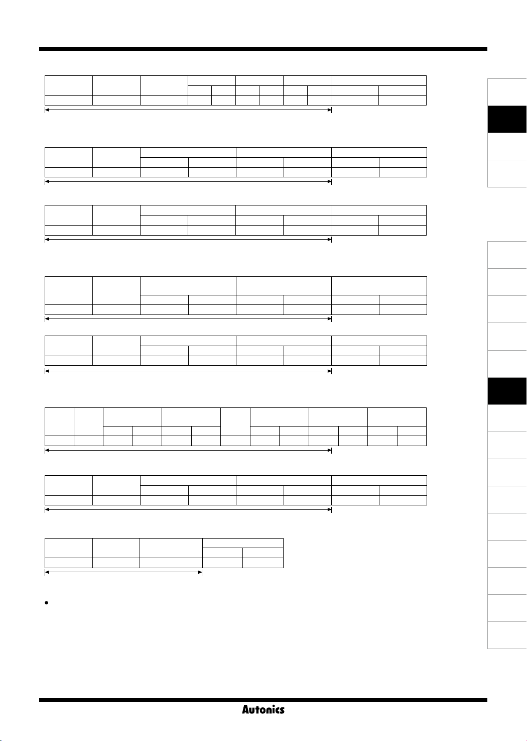
2) Response (Slave)
Slave Address
Function
(command)
Byte Count
(no. of data byte)
Data Data Data Error Check (CRC 16)
High Low High Low High Low Low High
1Byte 1Byte 1Byte 1Byte 1Byte 1Byte 1Byte 1Byte 1Byte 1Byte 1Byte
CRC16
5-3. Force single coil (func 05 H)
1) Query (Master)
Slave Address
Function
(command)
Coil Address Force Data Error Check (CRC 16)
High Low High Low Low High
1Byte 1Byte 1Byte 1Byte 1Byte 1Byte 1Byte 1Byte
CRC16
2) Response (Slave)
Slave Address
Function
(command)
Coil Address Force Data Error Check (CRC 16)
High Low High Low Low High
1Byte 1Byte 1Byte 1Byte 1Byte 1Byte 1Byte 1Byte
CRC16
5-4. Preset single register (func 06 H)
1) Query (Master)
Slave Address
Function
(command)
Register Address Preset Data Error Check (CRC 16)
High Low High Low Low High
1Byte 1Byte 1Byte 1Byte 1Byte 1Byte 1Byte 1Byte
2) Response (Slave)
Slave Address
Function
(command)
Register Address Preset Data Error Check (CRC 16)
High Low High Low Low High
CRC16
1Byte 1Byte 1Byte 1Byte 1Byte 1Byte 1Byte 1Byte
CRC16
5-5. Preset multiple registers (func 10 H)
1) Query (Master)
Slave
Address
Starting Address No. of Register
Function
(command)
High Low High Low High Low High Low Low High
Data Data
Byte
Count
Error Check
(CRC 16)
1Byte 1Byte 1Byte 1Byte 1Byte 1Byte 1Byte 1Byte 1Byte 1Byte 1Byte 1Byte 1Byte
CRC16
2) Response (Slave)
Slave Address
Function
(command)
Starting Address No. of Register Error Check (CRC 16)
High Low High Low Low High
1Byte 1Byte 1Byte 1Byte 1Byte 1Byte 1Byte 1Byte
CRC16
5-6. Exception response-error code (exception processing)
Slave Address
Function
+80H
Exception code
Error Check (CRC 16)
Low High
1Byte 1Byte 1Byte 1Byte 1Byte
CRC16
SENSORS
CONTROLLERS
MOTION DEVICES
SOFTWARE
(J)
Temperature
Controllers
(K)
SSRs
(L)
Power
Controllers
(M)
Counters
(N)
Timers
(O)
Digital
Panel Meters
(P)
Indicators
(Q)
Converters
(R)
Digital
Display Units
(S)
Sensor
Controllers
(T)
Switching
Mode Power
Supplies
(U)
Recorders
(V)
HMIs
When a communication error occurs, the highest bit from the received command (function) is set (1), a response command is sent, and the
corresponding exception code is transmitted.
(1) ILLEGAL FUNCTION (exception code: 01 H)
: Unsupported command
(2) ILLEGAL DATA ADDRESS (exception code: 02 H)
: The requested start address does not not match the transmission address of the device.
(3) ILLEGAL DATA VALUE (exception code: 03 H)
: The number of requested data does not match the transmission number of the device.
(4) SLAVE DEVICE FAILURE (exception code: 04 H)
: The requested command cannot be processed properly. (CRC)
O-95
(W)
Panel PC
(X)
Field Network
Devices
Page 21
MP5S/MP5Y/MP5W Series
-|Transparent setting guide|-
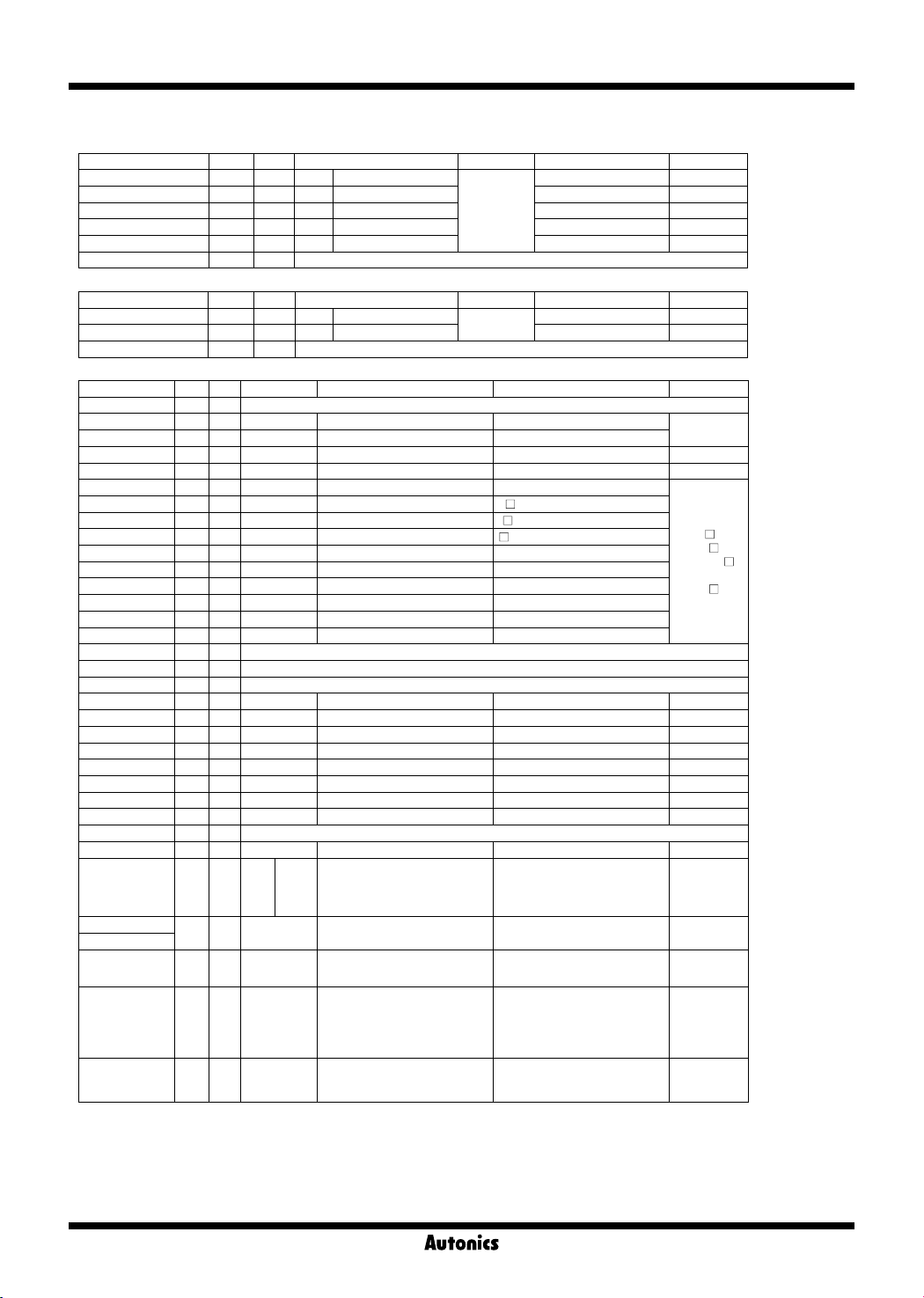
6. Address mapping table
6-1. Read coil status (func 01)
No.(Address) Func R/W Parameter Description Setting range Note
000001(0000) 01 R HH HH comparative output
000002(0001) 01 R H H comparative output 0: OFF / 1: ON
000003(0002) 01 R GO GO comparative output 0: OFF / 1: ON
000004(0003) 01 R L L comparative output 0: OFF / 1: ON
000005(0004) 01 R LL LL comparative output 0: OFF / 1: ON
000006 to 000050 01 R Reserved
Comparative
output
LED
6-2. Read input status (func 02)
No.(Address) Func R/W Parameter Description Setting range Note
100001(0000) 02 R
100002(0001) 02 R BANK BANK input status
100003 to 100050 02 R Reserved
RESET(HOLD)
External input
variables
6-3. Read input registers (func 04)
No.(Address) Func R/W Parameter Description Factory default Note
300001 to 300100 04 R Reserved
300101(0064) 04 R Product number H 0
300102(0065) 04 R Product number L 0
300103(0066) 04 R Hardware Version 1
300104(0067) 04 R Software Version 1
300105(0068) 04 R Model 1 "MP"
300106(0069) 04 R Model 2 "5
300107(006A) 04 R Model 3 "-
300108(006B) 04 R Model 4 "
300109(006C) 04 R Model 5 " "
300110(006D) 04 R Model 6 " "
300111(006E) 04 R Model 7 " "
300112(006F) 04 R Model 8 " "
300113(0070) 04 R Model 9 " "
300114(0071) 04 R Model 10 " "
300115(0072) 04 R Reserved
300116(0073) 04 R Reserved
300117(0074) 04 R Reserved
300118(0075) 04 R Coil Status Start Address 0000
300119(0076) 04 R Coil Status Quantity 0
300120(0077) 04 R Input Status Start Address 0000
300121(0078) 04 R Input Status Quantity 0
300122(0079) 04 R Holding Register Start Address 0000
300123(007A) 04 R Holding Register Quantity 0
300124(007B) 04 R Input Register Start Address 0000
300125(007C) 04 R Input Register Quantity 0
300126 to 300200 04 R Reserved
No.(Address) Func R/W Parameter Description Setting range Note
301001(03E8) 04 R
301002(03E9)
301003(03EA)
301004(03EB) 04 R DOT Decimal point
301005(03EC) 04 R UNIT Time range
301006(03ED) 04 R MODE Operation mode
04 R PV Measurement value -19999 to 99999
HH
H
GO
L
LL
Front
display
LED
HH LED Display
H LED Display
GO LED Display
L LED Display
LL LED Display
0: OFF / 1: ON
RESET input status
"
"
"
0: OFF
0: OFF
0: OFF
0: OFF
0: OFF
0:
00000
1:
000)0
2:
00)00
0: 999.99s
1: 9999.9s
2: 99m 59.9s
3: 9h 59m 59s
4: 99999s
0: F1
1: F2
2: F3
1: ON
1: ON
1: ON
1: ON
1: ON
3:
0)000
4:
)0000
5: 999.99m
6: 9999.9m
7: 99h 59.9m
8: 999h 59m
9: 99999m
to
14: F15
15: F16
Dedicated
model number
5,
MP5YMP5W- 8
(※MP5W- 9
displayed as
MP5W- 8)
0 Bit
1 Bit
2 Bit
3 Bit
4 Bit
O-96
Page 22

Pulse Meter
-|Transparent setting guide|-
6-4. Read holding registers (func 03) / Preset single register (func 06) / Preset multiple registers (func 16)
6-4-1. Comparative value settings and peak value check group
No.(Address) Func R/W Parameter Description Setting range Factory default
400001(0000)
400002(0001)
400003(0002)
400004(0003)
400005(0004)
400006(0005)
400007(0006)
400008(0007)
400009(0008)
400010(0009)
400011(000A)
400012(000B)
03/16 R/W
03/16 R/W
03/16 R/W
03/16 R/W
03/16 R/W
03/16 R/W
Preset HH
PStHH
Preset H H comparative value 0 to 99999 99999
PSt H
Preset L L comparative value 0 to 99999
PSt L
Preset LL LL comparative value 0 to 99999
PStLL
High Peak
hPEK
Low Peak
lPEK
400013 to 400050 03/06/16 R/W Reserved
※
1: In operation modes F8, F10, F14, F15,the setting range is -19999 to 99999
※
2: Max./Min. measurement value
6-4-2. Parameter 1 group
No.(Address) Func R/W Parameter Description Setting range Factory default
400051(0032) 03/06/16 R/W
400052(0033) 03/06/16 R/W
400053(0034) 03/06/16 R/W
400054(0035) 03/06/16 R/W
400055(0036) 03/06/16 R/W
400056(0037) 03/06/16 R/W
400057(0038) 03/06/16 R/W
400058(0039) 03/16 R/W
400059(003A) 03/16 R/W
400060(003B) 03/16 R/W
400061(003C) 03/16 R/W
400062(003D) 03/06/16 R/W
Mode Input operation mode
MODE
Input A
IN-A
Input B
IN-B
Output type Output mode
OUT-T
Hysteresis Hysteresis value 1 to 9999 1
HYS
Output limit Output limit function
GUArD
Start limit value
STArT
Auto-zero A
AUToA
Auto-zero B
AUToB
Memory Memory retention
MEMO
400063 to 400100 03/06/16 R/W Reserved
6-4-3. Parameter 2 group
No.(Address) Func R/W Parameter Description Setting range Factory default
400101(0064) 03/06/16 R/W
400102(0065) 03/06/16 R/W
400103(0066) 03/06/16 R/W
400104(0067) 03/06/16 R/W
Data bank Data bank
pBANK
Dot Decimal point
DOT
Time unit Time unit
tUNT
Time sec Time range
tSEC
HH comparative
value
High peak value
of measured value
Low peak value
of measured value
Sensor type
Start compensation
timer value
0 to 99999 99999
※
99999
-19999
0: F1
1: F2
2: F3
0:
NPnhF
1:
NPnmF
2:
NPnlF
3:
PNphF
4:
PNpmF
5:
PNplF
0:
STARD
1:
OUT-H
2:
OUT-L
3:
OUT-B
4:
OUT-I
5:
OUT-F
0:
fDEFY
1:
STArT
1
※
1
※
2
※
2
to
14: F15
15: F16
00000
00000
-
-
0
0
0
0
0.0 to 99.9 0.0
Auto-zero time 0.1 to 9999.9 9999.9
0:
OFF
1:
ON
0:
1
1:
2
0:
00000
1:
000)0
2:
00)00
3:
0)000
4:
)0000
0:
tSEC
1:
tMIN
0:
99(99
1:
999(9
2:
9(5(9
3:
(5(59
4:
99999
5:
99(99
6:
999(9
7:
9(5(9
8:
99(59
9:
99999
999.99s
9999.9s
99m 59.9s
9h 59m 59s
99999s
999.99m
9999.9m
99h 59.9m
999h 59m
99999m
0
0
0
0
0
SENSORS
CONTROLLERS
MOTION DEVICES
SOFTWARE
(J)
Temperature
Controllers
(K)
SSRs
(L)
Power
Controllers
(M)
Counters
(N)
Timers
(O)
Digital
Panel Meters
(P)
Indicators
(Q)
Converters
(R)
Digital
Display Units
(S)
Sensor
Controllers
(T)
Switching
Mode Power
Supplies
(U)
Recorders
(V)
HMIs
(W)
Panel PC
(X)
Field Network
Devices
O-97
Page 23
MP5S/MP5Y/MP5W Series
-|Transparent setting guide|-
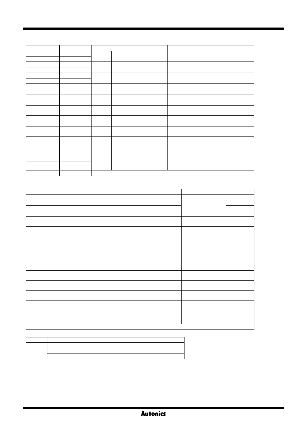
6-4-3. Parameter 2 group
No.(Address) Func R/W Parameter Description Setting range Factory default
400105(0068) 03/16 R/W
400106(0069) 03/16 R/W
400107(006A) 03/16 R/W
400108(006B) 03/16 R/W
400109(006C) 03/16 R/W
400110(006D) 03/16 R/W
400111(006E) 03/16 R/W
400112(006F) 03/16 R/W
400113(0070) 03/16 R/W
400114(0071) 03/16 R/W
400115(0072) 03/06/16 R/W
400116(0073) 03/16 R/W
400117(0074) 03/16 R/W
400118(0075) 03/06/16 R/W
400119(0076) 03/06/16 R/W
400120(0077) 03/16 R/W
400121(0078) 03/16 R/W
400122 to 400150 03/06/16 R/W Reserved
※
1: In operation modes F8, F10, F14, F15, the setting range is -19999 to 99999
Preset HH
PStHH
Preset H
PSt H
Preset L
PSt L
Preset LL
PStLL
Prescale A
PScaH
Mantissa
Prescale A
PScaY
Exponent
Prescale B
PScbH
Mantissa
Prescale B
PScbY
Exponent
Display time Display cycle
DISpT
INB
COUnB
Setting value
6-4-4. Parameter 3 group
No.(Address) Func R/W Parameter Description Setting range Factory default
400151(0096)
400152(0097)
400153(0098)
400154(0099)
400155(009A) 03/06/16 R/W
400156(009B) 03/06/16 R/W
400157(009C) 03/06/16 R/W
400158(009D) 03/06/16 R/W
400159(009E) 03/06/16 R/W
400160(009F) 03/06/16 R/W
400161(00A0) 03/06/16 R/W
400162(00A1) 03/06/16 R/W
400163 to 400200 03/06/16 R/W Reserved
※
1: High-limit/low-limit setting value of PV transmission output. (varies by model and operation mode)
Series Operation mode Setting range
MP5Y
MP5W
03/16 R/W
03/16 R/W
F1, F2, F7, F9, F11, F12, F13, F16 0 to 99999
F3, F4, F5, F6 0.01 to set time range
F8, F10, F14, F15 -19999 to 99999
Full scale High
FS-H
Full scale Low
FS-L
mA
MA
Unit address Communication address 1 to 99 1
ADDR
Bit per Sec Communication Speed
BPS
Parity bit
PRTY
Stop bit Communication stop bit
STP
Response
RSwT
waiting time
Communi
COmW
cation write
Lock Lock
LOC
HH comparative
value
H comparative
value
L comparative
value
LL comparative
value
Prescale A
mantissa
Prescale A
exponent
Prescale B
mantissa
Prescale B
exponent
Operation
mode
F16 INB
High-limit value of PV
transmission output
Low-limit value of PV
transmission output
Transmission output
spec.
Communication parity
bit
Communication
response waiting time
Communication write
enable/disable
0 to 99999 99999
0 to 99999 99999
0 to 99999
0 to 99999
0.0001 to 9.9999 6.0000
00 to 09: + (0 to 9)
10 to 19: - (0 to 9)
0.0001 to 9.9999 6.0000
00 to 09: + (0 to 9)
10 to 19: - (0 to 9)
0:
OFF
1:
)05
2:
)5
3:
1
1 to 99999 99999
※
1
※
1
4:
2
5:
4
6:
8
Setting range varies by
model and operation
※
1
mode
0:
(mA)
4-20
1:
(mA)
0-20
0:
2400
1:
4800
2:
9600
3:
19200
4:
38400
0:
NONE
1:
EVEN
2:
ODD
0:
1
1:
2
5 to 99(ms) 20
0:
DISA
1:
ENA
0:
OFF
1:
LOc0
2:
LOc1
3:
LOc2
4:
LOc3
0
0
01
01
1
99999
0
0
2
0
1
0
0
O-98
Page 24
Pulse Meter
-|Transparent setting guide|-
Comprehensive Device Management Program
▣
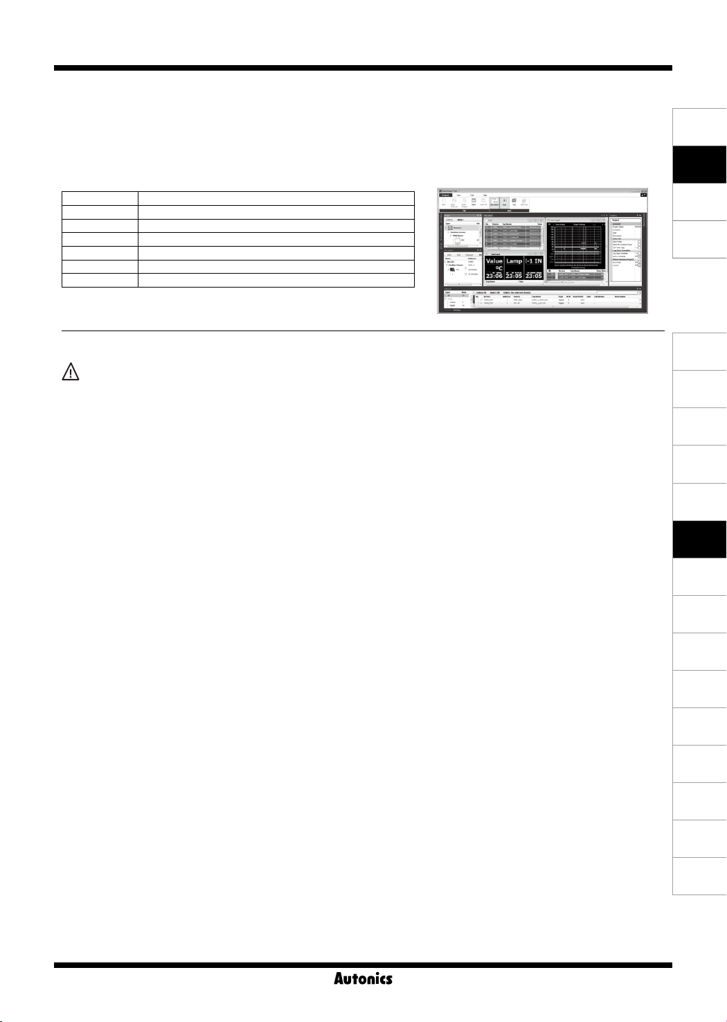
● DAQMaster is comprehensive device management program for convenient management of parameters and multiple
device data monitoring.
● Visit our website (www.autonics.com) to download user manual and comprehensive device management program.
Item Minimum requirements
System IBM PC compatible computer with Intel Pentium Ⅲ or above
Operations
Memory 256MB+
Hard disk 1GB+ of available hard disk space
VGA Resolution: 1024×768 or higher
Others RS-232 serial port (9-pin), USB port
Microsoft Windows 98/NT/XP/Vista/7/8/10
(DAQMaster)
< DAQMaster screen >< Computer specication for using software >
SENSORS
CONTROLLERS
MOTION DEVICES
SOFTWARE
▣ Proper Usage
Cautions during use
1. Follow instructions in 'Cautions during Use'. Otherwise, it may cause unexpected accidents.
2. 24VAC, 24-48VDC power supply should be insulated and limited voltage/current or Class 2, SELV power supply device.
3. Install a power switch or circuit breaker in the easily accessible place for supplying or disconnecting the power.
4. Keep away from high voltage lines or power lines to prevent inductive noise.
In case installing power line and input signal line closely, use line filter or varistor at power line and shielded wire at input
signal line.
Do not use near the equipment which generates strong magnetic force or high frequency noise.
5. This unit may be used in the following environments.
① Indoors (in the environment condition rated in 'Specifications')
② Altitude max. 2,000m
③ Pollution degree 2
④ Installation category II
(J)
Temperature
Controllers
(K)
SSRs
(L)
Power
Controllers
(M)
Counters
(N)
Timers
(O)
Digital
Panel Meters
(P)
Indicators
(Q)
Converters
(R)
Digital
Display Units
(S)
Sensor
Controllers
(T)
Switching
Mode Power
Supplies
O-99
(U)
Recorders
(V)
HMIs
(W)
Panel PC
(X)
Field Network
Devices
 Loading...