

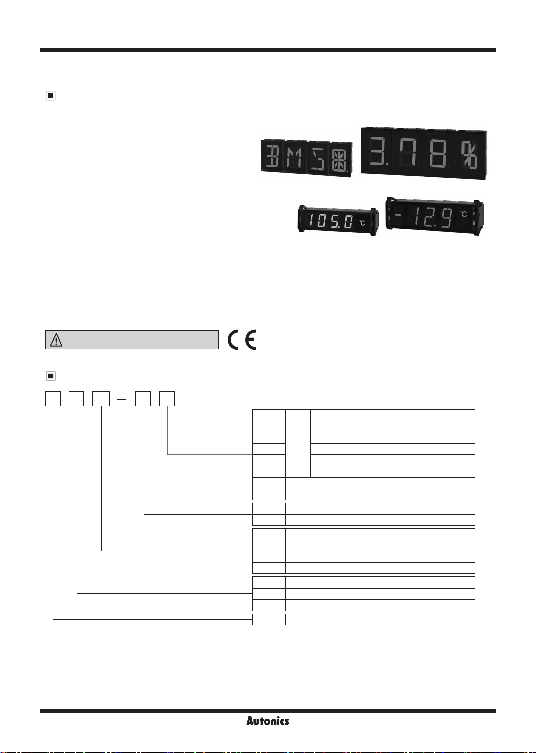
DS/DA Series
Intelligent Display Unit
Features
● Simple wiring without soldering
: multi-stage connection using expansion connectors or
ribbon cables.
: power supply and data wiring required on base
unit only.
● Various input options
: Serial input
: Parallel input
: RS485 communication input
: RS485 communication time sync display
: PT temperature sensor input
: PT temperature sensor + RS485 communication input
● Expandable up to 24 units with multi-stage connection
● Available in various sizes: 16mm, 22.5mm, 40mm, 60mm
● Available in 7-segment display and 16-segmentt display types
● Available in red display and green display types
● High luminance LED display
● Various unit display plates (switchable) with ashing or ON/OFF options
● Display 64 unique characters (0 to 9, A to Z, 27 symbols, period)
DS(A)40
DS(A)60
DS16 DS(A)22
Please read “Safety Considerations”
in the instruction manual before using.
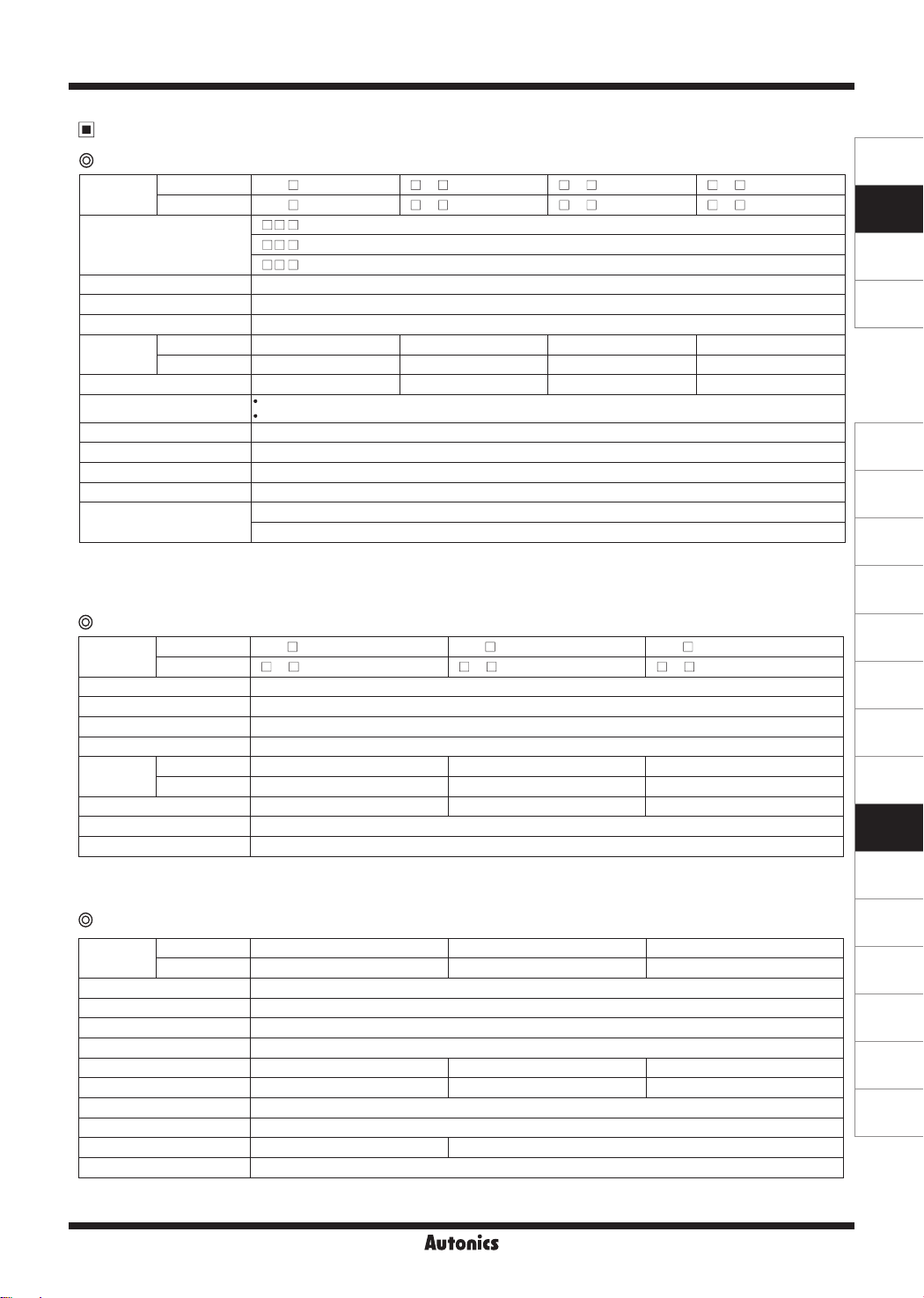
Ordering Information
D S 16 R S
Display color
Size (character size)
Display method
Item
Unit type
S
P Parallel input
T RS485 comm. input
C RS485 synchronous comm. type for time display
R Pt temp. sensor input
RT Pt temp. sensor input+RS485 comm. output
E Expansion unit
No-mark Unit-display unit
※
3
R
G Green
※
1
16
22 W20×H33mm (W11.2×H22.5mm)
40 W40×H60mm (W22.4×H40.0mm)
60 W60×H96mm (W33.6×H60.0mm)
S 7-segment
A 16-segment
※
2
U
D Display unit
Serial input
Basic
unit
Red
W16×H24mm (W9.0×H16.0mm)
Unit-display unit
※
1: The '16' size model has the serial input model, RS485 comm. input model and does not support 16-segment display method.
※
2: Unit-display unit has only 16, 22 size.
※
3: Pt temp. sensor input, Pt temp. sensor input+RS485 comm. output models support only red display color.
R-6
Intelligent Display Unit
Specifications
Serial / Parallel / RS485 communication input type
Model
Basic unit
Expansion unit
Input method
Display color Red, green (selectable by model)
Power supply 12-24VDCᜡ
Allowable voltage range 90 to 110% of rated voltage
Current
consumption
Red Max. 20mA Max. 25mA Max. 55mA Max. 65mA
Green Max. 15mA Max. 20mA Max. 40mA Max. 45mA
Character size W9×H16mm W11.2×H22.5mm W22.4×H40mm W33.6×H60mm
※
Max. Clock
Input logic
Input resistance
Input level
1, ※2
※
1
※
1
※
1
Display character 64 characters and signs (0 to 9, A to Z, 27 symbols, decimal point)
Max. connection
※
1: It is only for Serial, Parallel input models.
※
2: Max. Clock is for 1:1 of duty ratio (ON, OFF ratio).
DS16- S/T D 22- S/P/T D 40- S/P/T D 60- S/P/T
DS16- E D 22- E D 40- E D 60- E
D - S: Serial
D - P: Parallel (dynamic parallel 1, dynamic parallel 2)
D - T: RS485 communication (modbus protocol)
Serial input: max. 2kHz
Parallel input - dynamic parallel 1: max. 3kHz, dynamic parallel 2: max. 1.5kHz
Selectable positive logic (PNP), negative logic (NPN) (change by the function set switch)
20kΩ
High: 4.5-24VDCᜡ, low: 0-1.2VDC
ᜡ
Serial / RS485 comm. input: 24 units
Parallel input - dynamic parallel 1: 6 units (4-bit), 4 units (6-bit), dynamic parallel 2: 24 units (6-bit)
SENSORS
CONTROLLERS
MOTION DEVICES
SOFTWARE
(J)
Temperature
Controllers
(K)
SSRs
(L)
Power
Controllers
(M)
Counters
RS485 synchronous communication type for time display
Model
Basic unit
Expansion unit
Input method RS485 communication (modbus protocol)
Display color Red, green (selectable by model)
Power supply 12-24VDCᜡ
Allowable voltage range 90 to 110% of rated voltage
Current
consumption
Red Max. 25mA Max. 55mA Max. 65mA
Green Max. 20mA Max. 40mA Max. 45mA
Character size W11.2×H22.5mm W22.4×H40mm W33.6×H60mm
Time display World local time, 12/24-hour, summer time supported
Max. connection 10 units
※
1: Use 16-segment expansion unit for displaying delimiter for hour/min/sec and 'M' character for AM/PM.
DS22- C DS40- C DS60- C
D 22- E D 40- E D 60- E
Pt temp. sensor input / Pt temp. sensor input + RS485 communication ouput type
Model
Basic unit
Expansion unit
Input method Pt temp. sensor input (supports DPt100Ω, JPt 100Ω)
Display color Red
Power supply 12-24VDCᜡ
Allowable voltage range 90 to 110% of rated voltage
Current consumption Max. 40mA Max. 55mA Max. 65mA
Character size W11.2×H22.5mm W22.4×H40mm W33.6×H60mm
Display temp. range -50.0 to 400.0℃ or -58.0 to 752.0
Display accuracy F.S.±0.5%
Output
Max. connection 4 units (except unit-display unit)
※
1: RS485 comm. output supports only DS40-RRT, DS60-RRT models.
DS22-RR DS40-RR/RRT DS60-RR/RRT
DS22-RE DS40-RE DS60-RE
℉
※
-
RS485 comm. output (modbus RTU)
1
(N)
Timers
(O)
Digital
Panel Meters
(P)
Indicators
(Q)
Converters
(R)
Digital
Display Units
(S)
Sensor
Controllers
(T)
Switching
Mode Power
Supplies
(U)
Recorders
(V)
HMIs
(W)
Panel PC
(X)
Field Network
Devices
R-7
DS/DA Series
General Specifications
Model
Basic unit
Expansion unit
Noise immunity ±500V the square wave noise (pulse width: 1μs) by the noise simulator
Environment
Accessory
Ambient temp. -10 to 55℃, storage: -25 to 65
Ambient humi. 35 to 85%RH, storage: 35 to 85%RH
Basic unit Right/Left cap: 1
Expansion unit
Protection structure IP40 (front part)
Approval
Weight
※
※
※
※
Expansion unit
1: It is only for parallel input model.
2: The weight includes packaging. The weight in parenthesis is for unit only.
The weight represents a pack of 3 units. The weight in parenthesis is for 1 unit only.
3:
Environment resistance is rated at no freezing or condensation.
Basic unit
※
2
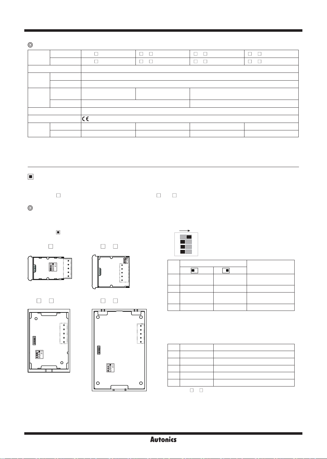
Unit Description and Function Setting
Only the basic unit model has the function set switch and the input terminal.
The DS16, D 22 models have them at the side, and the D 40. D 60 models have them at the rear.
DS16- S/T D 22- S/P/T/C/R D 40- S/P/T/C/R/RT D 60- S/P/T/C/R/RT
DS16- E D 22- E D 40- E D 60- E
℃
Right/Left cap: 1
Connector: 1
-
Connector: 1
Ribbon cable (50mm): 1
※
1
Approx. 52g (approx. 12g) Approx. 58g (approx. 17g) Approx. 63g (approx. 28g) Approx. 110g (approx. 60g)
Approx. 77g
(approx. 12g)
※
3
Approx. 92g
(approx. 17g)
※
3
Approx. 63g (approx. 28g) Approx. 110g (approx. 60g)
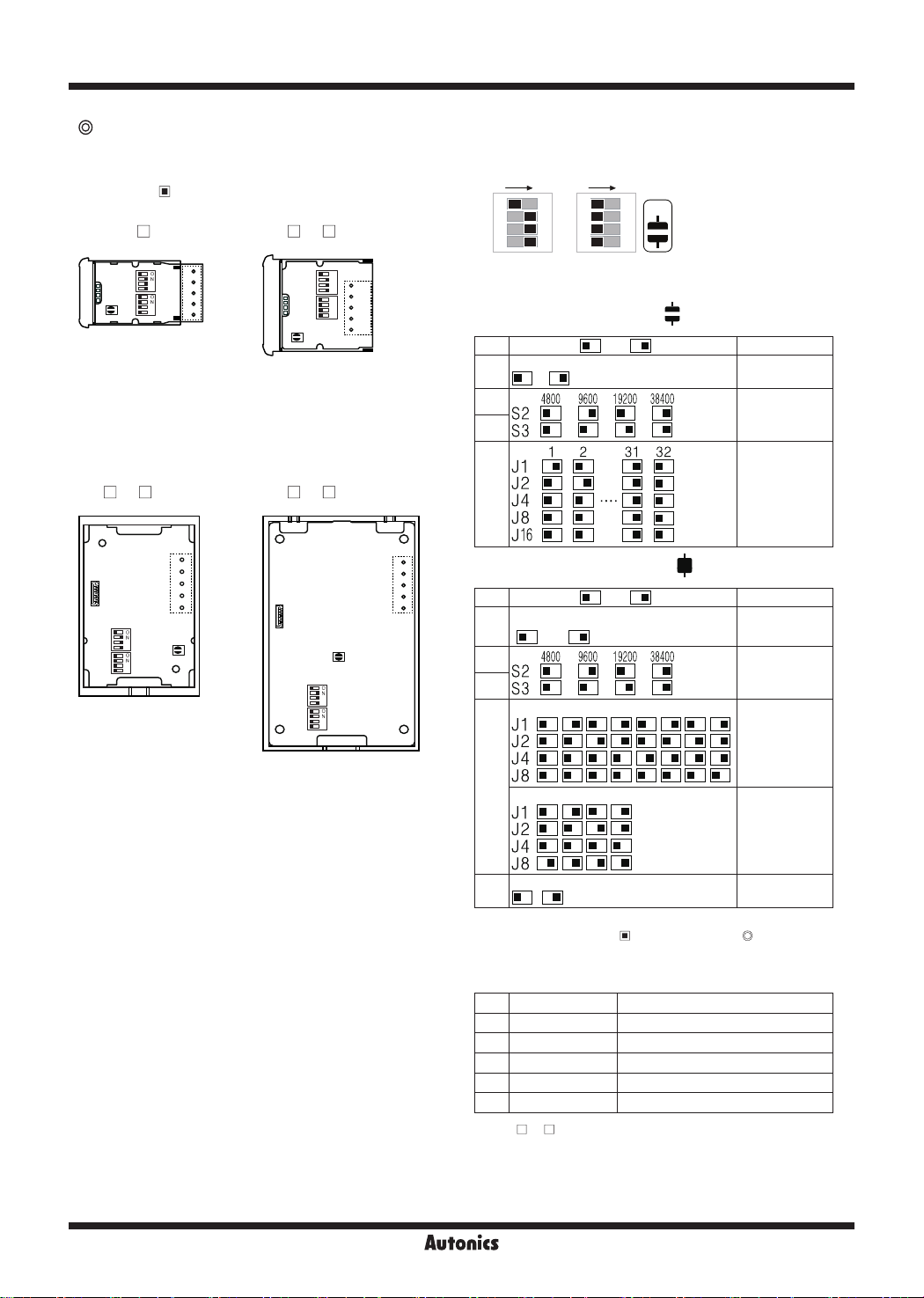
Serial input model
①
Expansion connector
Using for connecting units.
Refer to ' Connection of Units'.
● DS16- S ● D 22- S
②
S1
S2
S3
①
S4
5
4
3
2
1
● D 40- S ● D 60- S
③
1
2
3
①
①
S1
S2
②
S3
S4
②
4
5
③
②
①
①
S1
S2
②
S3
S4
②
Function set switches
ON
O
1
S1
S2
S3
S1
S2
S3
③
S4
5
4
3
2
1
S4
No.
S1
N
2
3
4
<factory default>
Switch
OFF( ) ON( )
Positive logic
(PNP)
Negative logic
(NPN)
Function
Input logic
S2 Not used Used Zero Blanking
S3 Not used Used
※
S4 8-bit 5-bit
※
1: The other data except 0 to 9 are blank.
※
③
1
2
3
4
5
2: 5-bit data input is compatible with Autonics panel meter
(MT4Y, MT4W).
③
Input terminal
2
Decimal number
※
1
display
Data input bit
No. Code Function
1 VCC 12-24VDC
2 GND 0V
3 Data Data input
4 CLOCK CLOCK input
5 LATCH LATCH input
※
For the D 22- S, connect the connector to input terminal.
R-8
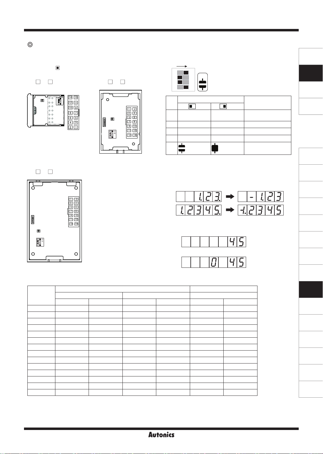
Parallel input model
Intelligent Display Unit
①
Expansion connector
Using for connecting units.
Refer to ' Connection of Units'.
● D 22- P
③
14
13
O
②
J1
①
N
12
11
10
②
9
8
7
6
5
4
3
2
1
● D 40- P
③
2
1
4
①
S1
S2
S3
S4
3
6
5
J1
②
8
7
10
9
12
11
14
13
②
Function set switches
ON
S1
2
S2
3
S3
4
S4
Switch
No.
OFF( ) ON( )
Positive logic
S1
(PNP)
S2 Not used Used Zero Blanking
S3 6-bit 4-bit
J1
N
<factory default>
Negative logic
(NPN)
※1,※
2
O
1
S4 Dynamic 1 Dynamic 2 Dynamic 1/2 selection
J1 All Zero Blanking
※
1: 4-bit data input is compatible with Autonics pulse meter
(MP5Y, MP5W) and panel meter (MT4Y, MT4W).
※
● D 60- P
2: 4-bit data input displays "-" or "-1" when dot display data at
the lowest display unit.
(minus display function is available when Zero Blanking, or
All Zero Blanking is set as ON)
③
2
1
4
3
6
5
8
①
J1
②
S1
S2
S3
S4
③
Input terminal
Terminal
7
10
9
12
11
14
13
※
3: When every number is '0', it becomes All Zero Blanking.
E.g.) When displaying 000045 using two basic units,
Uses All Zero Blanking
Basic
unit
Basic
unit
Does not use All Zero Blanking
Basic
unit
Basic
unit
Dynamic parallel 1 Dynamic parallel 2
4-bit data input 6-bit data input 6-bit data input
※
1
Code Function Code Function Code Function
1 VCC 12-24VDC VCC 12-24VDC VCC 12-24VDC
2 GND 0V GND 0V GND 0V
3 LE5 LATCH 5 LE3 LATCH 3 LATCH LATCH input
4 LE4 LATCH 4 LE2 LATCH 2 CLOCK CLOCK input
5 LE3 LATCH 3 LE1 LATCH 1
- -
6 LE2 LATCH 2 LE0 LATCH 0 UNIT Unit
7 LE1 LATCH 1 DP Decimal point DP Decimal point
8 LE0 LATCH 0 D5 25 Data D5 25 Data
9 DP Decimal point D4 24 Data D4 24 Data
10 D3 23 Data D3 23 Data D3 23 Data
11 D2 22 Data D2 22 Data D2 22 Data
12 D1 21 Data D1 21 Data D1 21 Data
13 D0 20 Data D0 20 Data D0 20 Data
14 GND 0V GND 0V GND 0V
※
1: When selecting Dynamic Parallel 2, 6-bit data input, All Zero Blanking OFF are xed.
Function
Input logic
Data input bit
SENSORS
CONTROLLERS
MOTION DEVICES
SOFTWARE
※
3
(J)
Temperature
Controllers
(K)
SSRs
(L)
Power
Controllers
(M)
Counters
(N)
Timers
(O)
Digital
Panel Meters
(P)
Indicators
(Q)
Converters
(R)
Digital
Display Units
(S)
Sensor
Controllers
(T)
Switching
Mode Power
Supplies
(U)
Recorders
(V)
HMIs
(W)
Panel PC
(X)
Field Network
Devices
R-9
DS/DA Series
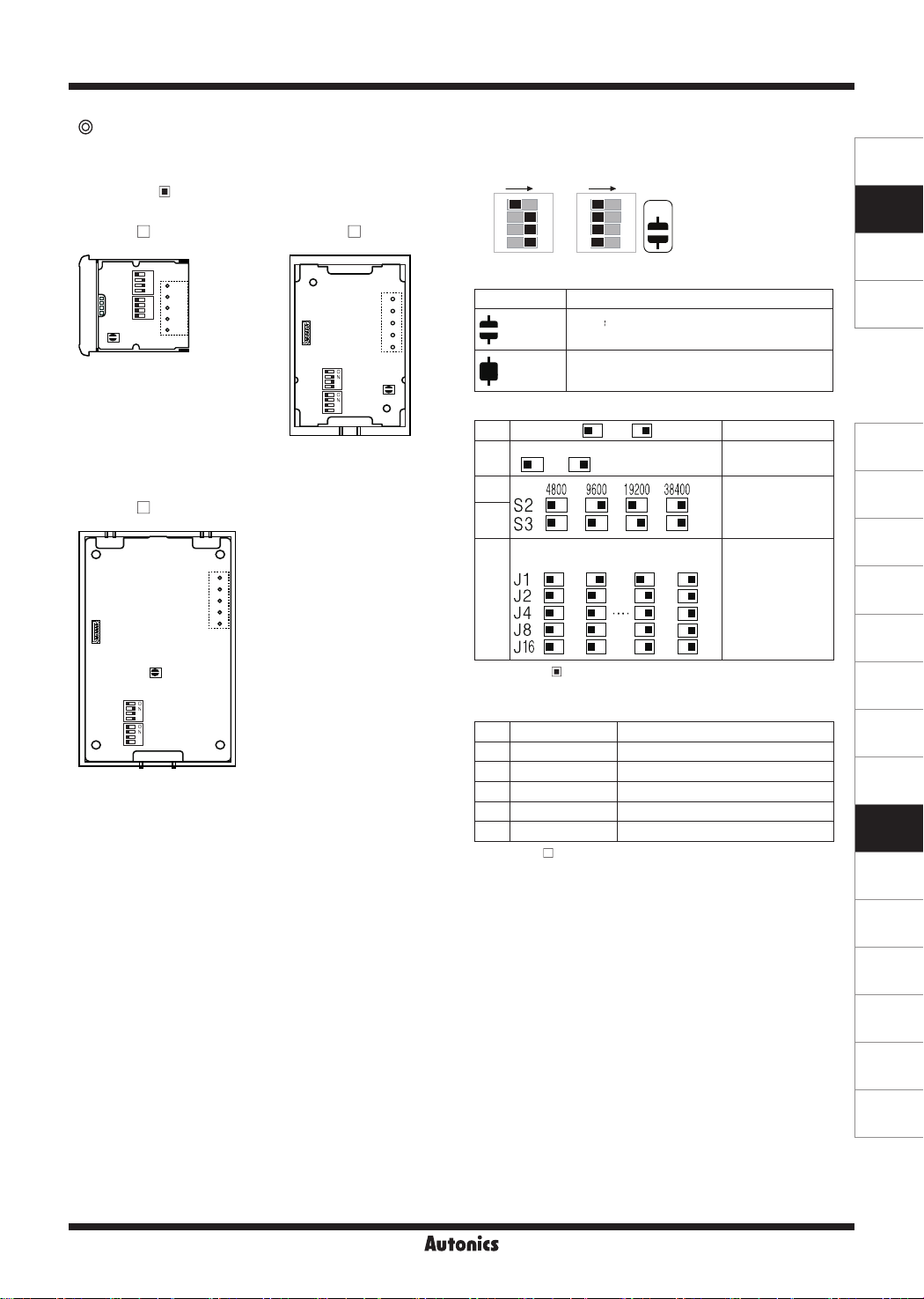
RS485 communication input model
①
Expansion connector
Using for connecting units.
Refer to ' Connection of Units'.
● DS16- T ● D 22- T
S1
①
S2
S3
J1
J2
J4
J8
J16
JP1
5
4
②
3
2
1
②
③
O
S1
N
S2
S3
①
J1
O
J2
N
J4
J8
J16
②
JP1
Function set switches
ONON
1 1
S1
2 2
S2
3 3
S3
4 4
J1
※
③
5
4
3
2
1
Functions are varied by JP1 setting (RS485 master mode/RS485
slave mode).
●RS485 slave mode (JP1 (open))
No.
S1
J2
O
N
J4
J8
J16
Switch OFF( )/ON( )
5ms 20ms
S2
S3
O
JP1
N
<factory default>
Function
Comm. response
time
Comm. speed
selection (bps)
● D 40- T ● D 60- T
③
①
S1
S2
②
S3
J1
J2
J4
J8
J16
1
2
3
4
5
JP1
①
S1
S2
S3
J1
J2
J4
J8
J16
J1
to
J16
③
1
●RS485 master mode (JP1 (short))
2
3
4
5
JP1
②
No. Switch OFF( )/ON( ) Function
Manual
Auto
setting
S1
setting
S2
S3
CT6 TK/TXCT4 MP5 TM4TM2MT4 THD
Comm. address
selection
Series setting
method
Comm.speed
selection (bps)
Series selection
(manual setting)
J1
to
J8
CT6 MP5 MT4 TK/TX
Series selection
(manual setting),
Not using the
highest digit
No Ye s
J16
※
RS485 Master mode supports only for Autonics RS485 comm.
Unit-display unit
output models. Refer to ' Data Input Method' ' RS485 comm.
(master mode) input model'.
③
Input terminal
No. Code Function
1 VCC 12-24VDC
2 GND 0V
3
- -
4 A (+) RS485 A (+)
5 B (-) RS485 B (-)
※
For D 22- T connect the connector to input terminal.
R-10
Intelligent Display Unit
RS485 synchronous communication type for time display model
①
Expansion connector
Using for connecting units.
Refer to ' Connection of Units'.
● DS22- C
O
S1
S2
①
S3
J1
J2
J4
J8
J16
②
JP1
③
N
5
O
4
N
3
2
1
● DS40- C
③
①
S1
S2
②
S3
J1
J2
J4
J8
J16
1
2
3
4
5
JP1
②
Function set switches
1 1
S1
2 2
S2
3 3
S3
4 4
J1
J2
O
N
J4
J8
J16
● JP1 terminal setting
JP1 Delimiter for hour/min/sec
(Open)
(Short)
Sign [ ]
(using 16-segment expansion unit)
Period [.]
(using 7-segment expansion unit)
● Switch setting
No. Switch OFF( )/ON( ) Function
24-hour 12-hour
S1
SENSORS
ONON
O
JP1
N
<factory default>
12/24-hour setting
CONTROLLERS
MOTION DEVICES
SOFTWARE
(J)
Temperature
Controllers
● DS60- C
①
S1
S2
S3
J1
J2
J4
J8
J16
S2
S3
UTC
UTC
-12:00
③
1
2
3
4
5
JP1
②
J1
to
J16
※
1: Refer to
③
Input terminal
No.
Code Function
-11:00
"
World Time Zone".
UTC
+11:00
UTC
+12:00
Comm. speed
selection (bps)
World time zone
※
selection
1
(K)
SSRs
(L)
Power
Controllers
(M)
Counters
(N)
Timers
(O)
Digital
Panel Meters
(P)
Indicators
1 VCC 12-24VDC
2 GND 0V
3
- -
4 A (+) RS485 A (+)
5 B (-) RS485 B (-)
※
For DS22- C connect the connector to input terminal.
(Q)
Converters
(R)
Digital
Display Units
(S)
Sensor
Controllers
(T)
Switching
Mode Power
Supplies
(U)
Recorders
R-11
(V)
HMIs
(W)
Panel PC
(X)
Field Network
Devices
DS/DA Series
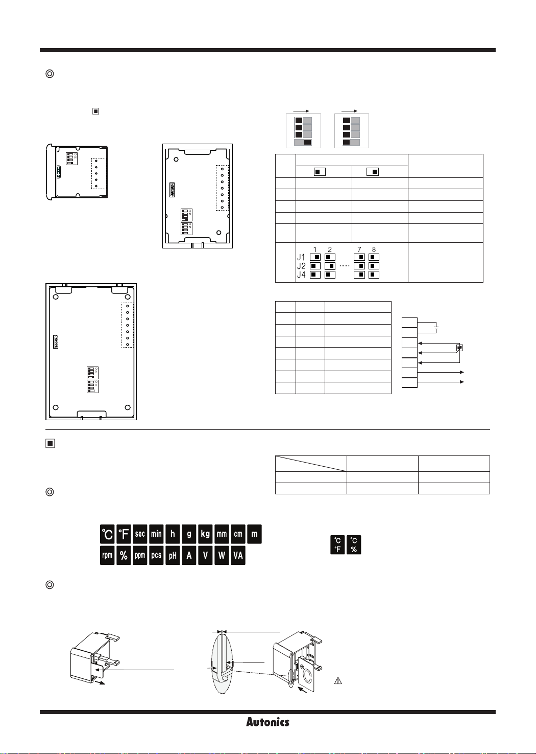
Pt temp. sensor input model
①
Expansion connector
Using for connecting units.
Refer to ' Connection of Units'.
● DS22-RR
S1
②
S2
S3
S4
①
③
5
4
3
2
1
● DS60-RR/RRT
①
S1
②
S2
S3
S4
S5
J1
J2
J4
③
1
2
3
4
5
6
7
● DS40-RR/RRT
①
S1
S2
②
S3
S4
S5
J1
J2
J4
②
Function set switches
ONON
1 1
S1
2 2
S2
3 3
S3
4 4
S4
③
1
2
3
4
5
6
7
No.
S1 DPt100Ω JPt100Ω Temp.sensor
S2
S3 10
S5
O
N
J1
J2
J4
Switch
OFF( ) ON( )
℃ ℉
2
O
N
<factory default>
Function
1
10
Temp. unit
Integer display
S4 Not used Used Decimal point
S5 9600bps 38400bps
J1
J2
J4
③
Input terminal
No.
Code Function
1 VCC 12-24VDC
2 GND 0V
3 A Pt temp. sensor A
4 B Pt temp. sensor B
5 B' Pt temp. sensor B'
6 A (+) RS485 A (+)
7 B (-) RS485 B (-)
※
For DS22-RR connect the connector to input terminal.
※
Function set switches S5, J1, J2, J4 and input terminal 6, 7 are
Comm. speed
selection (bps)
Comm. address
selection
● Connections
+
1
2
3
4
5
6
7
12-24VDC
-
A
B
B'
RS485 A(+)
RS485 B(-)
DPt100Ω,
JPt100Ω
only for RS485 comm. ouptut models (DS40-RRT, DS60-RRT).
Unit-display Unit
This unit is for displaying unit by inserting a name plate.
It has only 16, 22 sizes. (sold separately)
Unit name plates
● Model
Size
16mm DU16-R DU16-G
22mm DU22-R DU22-G
Color
Red Green
It provides unit-printed name plates as an accessory. You can select the desired unit name plate and insert this plate.
(single-stage unit name plate: 19 types, dual-stage unit name plate: 2 types)
Dual-stage unit name plate
Single-stage unit name plate
Unit name plate insertion
Remove the protection sheet and insert the unit name plate at between the case and the reflector.
Unit name plate
insertion space
Reector
Caution: Be sure about the correct
insert direction.
R-12
Protection sheet
Case
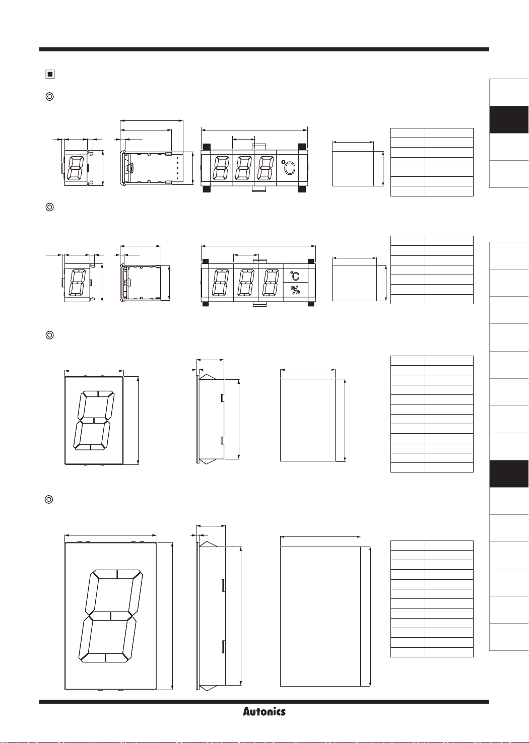
Dimensions
DS16/DU16
42 16
24
DS22/DA22/DU22
3.5
42.8
35
Intelligent Display Unit
(unit: mm)
※
N: Number of units
※
16N+13
16
● Panel cut-out
±0.5
A
22
Panel thickness: 1.5 to 4mm
Units (N) A (16N+11)
1 27
2 43
3 59
0
4 75
23
-0.5
5 91
: :
SENSORS
CONTROLLERS
MOTION DEVICES
SOFTWARE
42.2
20
33
DS40/DA40
40
DS60/DA60
● Panel cut-out
±0.5
A
Units (N) A (20N+11)
1 31
2 51
(J)
Temperature
Controllers
3.5
35
20N+13
20
3 71
0
4 91
30
19
2
● Panel cut-out
±0.5
A
5 111
31
-0.5
: :
Units (N) A (40N-2)
1 38
2 78
3 118
4 158
0
60
54
55
-0.5
5 198
6 238
7 278
8 318
9 358
(K)
SSRs
(L)
Power
Controllers
(M)
Counters
(N)
Timers
(O)
Digital
Panel Meters
(P)
Indicators
(Q)
Converters
10 398
: :
● Panel cut-out
60
2
19
±0.5
A
Units (N) A (60N-3)
1 57
2 117
3 177
4 237
(R)
Digital
Display Units
(S)
Sensor
Controllers
(T)
Switching
Mode Power
Supplies
(U)
Recorders
(V)
HMIs
5 297
6 357
0
96
90
91
-0.5
7 417
8 477
9 537
10 597
(W)
Panel PC
(X)
Field Network
Devices
: :
R-13

DS/DA Series
Accessories
Cap
DS16
32.8
24
6.5
32.8
24
6.5
Connector
D -P
: for Parallel input model
7.4
15.56.2
3.5
35
5
6.7
3.5
35
4
5
6.7
D 22 D 22
40.8
33
3.5
6.5
35
5
6.7
40.8
33
3.5
6.5
35
4
5
6.7
13.1
Ribbon cable
D 40/D 60
50
8.7
Sold Separately
Middle bracket
BK-D16R
( for DS16)
BK-D16R
( for D 22)
22.3
19.1
5.8
11.8
32.5
32.5
23.5
Communication converter
SCM-WF48
( Wi-Fi to RS485·USB wireless
communication converter)
R-14
10
SCM-US48I
(USB to RS485 converter)
32.5
40.5
SCM-38I
(RS232C to RS485 converter)
10
31.5

Intelligent Display Unit
Removing Protection Cover
To operate the function set switch of the D 40, D 60 models, you should remove the protection cover.
Press the connection parts (4-point) of the protection cover at the top/bottom of
the product with a flat-head screwdriver and the protection cover is removed.
SENSORS
CONTROLLERS
Flat-head
screw driver
Caution: Before removing the protection cover, power must be turned OFF.
Connection of Units
DS16/D 22
● Connect a basic unit, expansion units, a unit-display unit from the left and connect the caps the end of right and left.
● The middle bracket (sold separately) helps to protect deflection when connecting over 7 units.
Use one middle bracket per 7 units.
● The basic unit supplies the power for expansion units and the unit-display unit and DATA input.
Middle
bracket
Cap
※
Tighten it with below 0.5N·m.
Basic unit
Expansion unit
D 40/D 60
Connect expansion connectors of units using a ribbon cable (accessory) as (gure 1).
If the distance between expansion units is far as (gure 2), you can connect the cable at the soldering pad.
To use a soldering pad, remove the protection cover which only expansion units have.
Expansion connector
Cap
Unit-display unit
MOTION DEVICES
SOFTWARE
(J)
Temperature
Controllers
(K)
SSRs
(L)
Power
Controllers
(M)
Counters
(N)
Timers
(O)
Digital
Panel Meters
(P)
Indicators
(Q)
Converters
Expansion unit
Basic unit
Expansion unit 2
Soldering pad Soldering pad
Ribbon cable
(gure 1)
※
You can use both the 7-segment display method model and the 16-segment display method model mixed.
Cable length: max. 1m
(gure 2)
Expansion unit 1
R-15
(R)
Digital
Display Units
(S)
Sensor
Controllers
(T)
Switching
Mode Power
Supplies
(U)
Recorders
(V)
HMIs
(W)
Panel PC
(X)
Field Network
Devices

DS/DA Series
Input Data Chart [Serial, Parallel, RS485 Comm.(Slave Mode) Input Model]
When selecting 5-bit data input for the serial input model, or 4-bit data input for the parallel input model, it dis-
plays only shaded part (0 to 9, A to F)
displays by each input method; serial input model displays ‘S’, parallel input model displays ‘P’, and RS485 communication
input model displays ‘T’.
DS Series (7-segment) DA Series (16-segment)
D5 D4 D5 D4 D5 D4 D5 D4 D5 D4 D5 D4 D5 D4 D5 D4 D5 D4
L L L H H L H H L L L H H L H H X X
0
1 H
2 I
3
4
5
6
7
8 O
9
A
B
C S
D
E
F
※
1: If this data is not for the unit-display unit, it maintains former state.
※
The unit-display unit does not use the upper bit over D4. (don’t care: X)
※
Unit-display unit function
K
L
N
P
Q
R
T
U
V
W
(
₩
)
H (h)
'
"
.
/ N
-
Blank
]
˚
I
J
K
K
O
T
X
G
X
Y
Z
J
-1
M
^
?
_
=
Upper/Lower selection, ON/Flash function ON/Flash function
. If there is no input data after supplying the power, the basic unit differently
※
In case of positive logic (PNP)
G
0
1 H X
2
3
4 K -1 ;
5 L (
M
6
7 N ' |
O
8
9 P ^
A Q
B R / $
C
D
E U _
F
W ]
Y +
I
J Z
) >
" !
.
S ? %
T
V
- &
Blank
=
[
:
<
@
#
★
DU Series
No unit
UpperLower OFF
Upper-Lower
ON
Upper ON
Lower ON
Upper-Lower
ashes
Upper
ashes
Lower
ashes
※
(unit)
1
Hi 2-bit
Low 4-bit
D3 D2 D1 D0
L L L L
L L L H
L L H L
L L H H
L H L L
L H L H
L H H L
L H H H
H L L L
H L L H
H L H L
H L H H
H H L L
H H L H
H H H L
H H H H
※
It is only available to use the unit-display unit with serial 5-bit, parallel 4/6-bit Dynamic 1 input when connecting the unit
display unit and turning ON it. (do not input data to the unit-display unit.)
※
To display two data using zero blanking function
Using the unit-display unit: If sending unit data signal after data 1 (00123), it applies zero blanking function when displaying
①
data 2 (04567).
Not using the unit-display unit: If sending no-unit data (HXXXLLLL) after data 1 (00123), it applies zero blanking function
②
to display data 2. In this case, transmitted data should be added one to the display digits. (no-unit data is added)
When do not using unit-display unit, no-unit data is used for data division. If it does not send no-unit data (HXXXLLLL),
it displays data 1 (00123) and data 2 (04567) as one data. Zero-blanking function is applied to data 1 only.
※
Do not transfer unit data to basic/expansion unit. Unit bit (D7) of unit data is only for unit. If transferring unit data to basic/
expansion unit, unit bit (D7) displays the ignored data value. In this case, Zero blanking does not operate normally.
R-16

Intelligent Display Unit
Data Input Method [Serial, Parallel, RS485 Comm. Input Model]
Serial input model
● 5-bit serial input (e.g.: displays 12.8℃)
※
Clock: max. 2kHz
※
START
LATCH
CLOCK
1-bit Data
SHIFT
L
L L L H
D4
0.5ms
H H HL L L L L L L
D4 D4D3
D3 D3D2
D2 D2D1
D1 D1D0
D0 D0
These are examples for positive logic (PNP).
tw
ta: 0.2ms (min.)
ta
tw: 0.25ms (min.)
SENSORS
CONTROLLERS
MOTION DEVICES
SOFTWARE
Point
Data
MSB (2)
Point
LSB (2)
Data Data
MSB (1)
Point
LSB (1)
MSB (0)
LSB (0)
Caution: The unit-display unit is available only for turning ON. Do not input data to the unit-display unit.
● 8-bit serial input (e.g.: displays 25℃)
Unit
Point
ta: 0.2ms (min.)
tw: 0.25ms (min.)
ta
MSB (0)
START
LATCH
CLOCK
1-bit Data
SHIFT
L L L L L L L L L L L L L L L L
Unit
D4 D4 D4D5 D5 D5D6 D6 D6D7 D7 D7
Point
MSB (2)
H H H H HX X X
D3 D3 D3
D2 D2 D2
D1 D1 D1
Data Data Data
0.5ms
D0 D0 D0
Unit
Point
LSB (2)
MSB (1)
LSB (1)
Parallel input model
Example of unit organization by data input
Connectable 1 basic unit and 5 expansion units (6-digit)
4-bit
Dynamic Parallel 1
Dynamic Parallel 2 6-bit
● 4-bit dynamic parallel 1 transmission (e.g.: displays ACE007.)
Basic unit
4-bit
Data
Point
LATCH
0 to 5
※
Pw=t1+t2+t3
Pw: 0.33ms (min.)
t1: 0.05ms (min.) → Data LATCH
t2: 0.23ms (min.) → Data move
t3: 0.05ms (min.) → Data LATCH
E.g.) 10-digit organization: (1 basic unit + 5 expansion units)+ (1 basic unit + 3 expansion units)
Connectable 1 basic unit and 3 expansion units (4-digit)
6-bit
E.g.) 10-digit organization: (1 basic unit + 3 expansion units)×2+ (1 basic unit + 1 expansion units)
Connectable 1 basic unit and 23 expansion units (24-digit)
E.g.) 30-digit organization: (1 basic unit + 23 expansion units)+ (1 basic unit + 5 expansion units)
Expansion
unit 1
Expansion
unit 5
4-bit
Data
Point
LATCH 0
LATCH 1
LATCH 2
LATCH 3
LATCH 4
LATCH 5
Pw
HLHL HHLL HHHL LLLL LLLL LHHH
t1 t3
t2
※
Max. data input speed: 3kHz
tw
LSB (0)
(J)
Temperature
Controllers
(K)
SSRs
(L)
Power
Controllers
(M)
Counters
(N)
Timers
(O)
Digital
Panel Meters
(P)
Indicators
(Q)
Converters
(R)
Digital
Display Units
(S)
Sensor
Controllers
(T)
Switching
Mode Power
Supplies
(U)
Recorders
(V)
HMIs
(W)
Panel PC
(X)
Field Network
Devices
R-17

DS/DA Series
● 4-bit dynamic parallel 1 transmission (e.g.: displays 012345.6789)
Expansion
Basic unit1 Basic unit2
4-bit
Data
Point
LATCH
0 to 5
LATCH
6 to 9
4-bit
Data
Point
LATCH 0
LATCH 1
LATCH 2
LATCH 3
LATCH 4
LATCH 5
LATCH 6
LATCH 7
LATCH 8
LATCH 9
unit 1
LLLL LLLH LLHL
t1 t2 t3
Pw
Expansion
unit 5
LLHH LHLL
Expansion
unit 8
※
Pw=t1+t2+t3
Pw: 0.33ms (min.)
t1: 0.05ms (min.) → Data LATCH
t2: 0.23ms (min.) → Data move
t3: 0.05ms (min.) → Data LATCH
※
Max. data input speed: 3kHz
LHLH
LHHL LHHH HLLL HLLH
● 6-bit dynamic parallel 1 transmission (e.g.: displays 50.80kg)
Basic unit
6-bit
Data
Point
LATCH
0 to 3
※
Pw=t1+t2+t3
Pw: 0.33ms (min.)
t1: 0.05ms (min.) → Data LATCH
t2: 0.23ms (min.) → Data move
t3: 0.05ms (min.) → Data LATCH
Expansion
unit 1
Expansion
unit 2
Expansion
unit 3
6-bit
Data
Point
LATCH 0
LATCH 1
LATCH 2
LATCH 3
Caution: The unit-display unit is available only for turning ON. Do not input data to the unit-display unit.
※
General parallel input is only for basic unit (dynamic parallel 1).
Basic unit Basic unit Basic unit Basic unit
4/6-bit Data3+Point3
4/6-bit Data2+Point2
4/6-bit Data1+Point1
4/6-bit Data0+Point0
LATCH 0
Pw
LLLHLH LLLLLL LLHLLL LLLLLL
t1 t3
t2
4/6-bit Data3+Point3
4/6-bit Data2+Point2
4/6-bit Data1+Point1
4/6-bit Data0+Point0
LATCH 0
※
Max. data input speed: 3kHz
Data3+DP3
Data2+DP2
Data1+DP
1
Data0+DP0
10310210110
0
R-18

Intelligent Display Unit
● 6-bit dynamic parallel 1 transmission (e.g.: displays-AUTONICS-)
Expansion
Basic unit1 Basic unit3Basic unit2
6-bit
Data
unit 1
Expansion
unit 3
Point
LATCH
0 to 3
LATCH
4 to 7
LATCH
8 to 9
Data
6-bit
HLHHLH LLHLHL LHHHHL LHHHLH LHHLLL LHLHHH LHLLHL LLHHLL LHHHLL HLHHLH
Pw
Point
LATCH 0
LATCH 1
t1 t3
t2
LATCH 2
LATCH 3
LATCH 4
LATCH 5
LATCH 6
LATCH 7
LATCH 8
LATCH 9
● 6-bit dynamic parallel 2 transmission (e.g.: displays AB.C... W˚F)
Expansion
6-bit
Data
Basic unit
unit 1
Point
Unit
CLOCK
LATCH
※
ta: 0.3ms (min.), tw: 0.33ms (min.)
※
Clock: max. 1.5kHz
Expansion
unit 23
LATCH
CLOCK
6-bit
Data
Point
Unit
Expansion
unit 6
Expansion
unit 7
※
Pw=t1+t2+t3
Pw: 0.33ms (min.)
t1: 0.05ms (min.) → Data LATCH
t2: 0.23ms (min.) → Data move
t3: 0.05ms (min.) → Data LATCH
※
Max. data input speed: 3kHz
0.66ms
LLHLHL LLHLHH LLHHLL HLLLLL XXLLHL
23
10
102210
21
10110
tw
ta
0
RS485 comm. (slave mode) input model
● E.g.: Displays 10H38M (10 hour 38 min)
Communication address: 1, Communication speed: 9600bps, Data bit: 8-bit, Start/Stop bit: 1-bit, Parity bit: none
Basic unit
RS485+
RS485-
Byte Counter
(No. of data byte)
08H 00H 01H 01H 00H 11 H 03H 08H 16H D4H 59H
• Response (slave)
Slave
Address
Function
01H 10H 00H 00H 00H 04H C1H CAH
Expansion
unit 1
Expansion
unit 23
• Query (master)
Slave
address
Function
Starting address No. of Register
High Low High Low
01H 10H 00H 00H 00H 04H
Data (400001) Data (400002) Data (400003) Data (400004)
Error check (CRC16)
High Low High Low High Low High Low Low High
Zero
Blanking
ON
Starting Address No. of Register Error Check (CRC16)
High Low High Low Low High
SENSORS
CONTROLLERS
MOTION DEVICES
SOFTWARE
(J)
Temperature
Controllers
(K)
SSRs
(L)
Power
Controllers
(M)
Counters
(N)
Timers
(O)
Digital
Panel Meters
(P)
Indicators
(Q)
Converters
(R)
Digital
Display Units
(S)
Sensor
Controllers
(T)
Switching
Mode Power
Supplies
(U)
Recorders
(V)
HMIs
(W)
Panel PC
(X)
Field Network
Devices
R-19

DS/DA Series
RS485 comm. (master mode) input model
Connect the unit and the specified Autonics device which supports master mode for displaying current value without PC/PLC.
The specified Autonics devices are connected by auto or manual setting.
● Supported Autonics device for RS485 master mode
Only for RS485 communication output model of the below series.
Item Series
Temperature
controller/sensor
TK, TX, TM2, TM4, THD
Counter/Timer CT4, CT6
Pulse meter MP5
S1
S2
S3
J1
J2
J4
J8
J16
JP1
Panel meter MT4
※
Connect input terminal 4(A+) and 5(B-) of display unit to RS485 communication output terminal of the dedicated device.
Examples of Display
RS485 communication input model
In case of manual connection setting, the highest digit may be not used.
1) CT6 Series (using 6-digit)
2) CT6 Series (using 5-digit)
5
4
3
2
1
RS485
comm.output
DEVICE
3) MP5 Series (using 5-digit)
4) MP5 Series (using 4-digit)
5) TM4 Series (4CH connection, using unit-display unit)
6) THD Series (using unit-display unit)
RS485 synchronous comm. type for time display model (delimiter for hour/min/sec)
※
Delimiter for hour/min/sec Displaying 24-hour Displaying 12-hour
Hour/Min
Sign [ ]
(using 16 seg. expansion unit)
Hour/
Min/Sec
Hour/Min
Period [.]
(using 7 seg. expansion unit)
※
Use 16-segment expansion unit for 'M' character for AM/PM when displaying 12 hours time.
Hour/
Min/Sec
1
Pt temp. sensor input model
1) Temperature (℃) display
(displays DPt100Ω, 400.0℃)
S1
S2
S3
S4
※
Pt temp. sensor input model are applied Zero Blanking function automatically.
R-20
2) Temperature (℉) display
(JPt100Ω, 75.2℉)
S1
S2
S3
S4

Intelligent Display Unit
Input Circuit
● Positive logic (PNP) input
Input
20kΩ
World Time Zone [RS485 Synchronous Comm. Type for Time Display Model]
※
Select the desired world time zone by function set switches (J1 to J16).
※
If communication is not connected when supplying the power, the unit displays the set local time zone.
Switch
No.
J1 J2 J4 J8 J16
0 0 0 0 0 0 UTC-12:00 International Date Line West
1 0 0 0 0 1 UTC-11:00 Coordinated Universal Time -11
2 0 0 0 1 0 UTC-10:00 Hawaii
3 0 0 0 1 1 UTC-09:00 Alaska
4 0 0 1 0 0 UTC-08:00 Pacic Time(US&Canada), Baja California
5 0 0 1 0 1 UTC-07:00 Mountain Time(US&Canada), Arizona, Chihuahua, La Paz, Mazatlan
6 0 0 1 1 0 UTC-06:00
7 0 0 1 1 1 UTC-05:00 Eastern Time(US&Canada), Indiana(East), Bogota, Lima, Quito, Rio Branco, Chetumal
8 0 1 0 0 0 UTC-04:00 Atlantic Time(Canada), Asuncion, Georgetown, La Paz, Manaus, San Juan, Cuiaba
9 0 1 0 0 1 UTC-03:30 Newfoundland
10 0 1 0 1 0 UTC-03:00 Greenland, Montevideo, Buenos Aires, Brasilia, Santiago, Salvador, Cayenne, Fortaleza
11 0 1 0 1 1 UTC-02:00 Coordinated Universal Time -02
12 0 1 1 0 0 UTC-01:00 Cabo Verde Is., Azores
13 0 1 1 0 1 UTC 00:00
14 0 1 1 1 0 UTC+01:00
15 0 1 1 1 1 UTC+02:00
16 1 0 0 0 0 UTC+03:00 Nairobi, Moscow, St. Petersburg, Volgograd, Minsk, Baghdad, Kuwait, Riyadh
17 1 0 0 0 1 UTC+03:30 Tehran
18 1 0 0 1 0 UTC+04:00 Baku, Abu Dhabi, Muscat, Yerevan, Izhevsk, Samara, Tbilisi, Port Louis
19 1 0 0 1 1 UTC+04:30 Kabul
20 1 0 1 0 0 UTC+05:00 Ashgabat, Tashkent, Ekaterinburg, Islamabad, Karachi
21 1 0 1 0 1 UTC+05:30 Sri Jayawardenepura, Chennai, Kolkata, Mumbai, New Delhi
22 1 0 1 1 0 UTC+05:45 Kathmandu
23 1 0 1 1 1 UTC+06:00 Novosibirsk, Dhaka, Astana
24 1 1 0 0 0 UTC+06:30 Yangon(Rangoon)
25 1 1 0 0 1 UTC+07:00 Bangkok, Hanoi, Jakarta, Krasnoyarsk
26 1 1 0 1 0 UTC+08:00
27 1 1 0 1 1 UTC+09:00 Seoul, Yakutsk, Osaka, Sapporo, Tokyo
28 1 1 1 0 0 UTC+09:30 Darwin, Adelaide
29 1 1 1 0 1 UTC+10:00 Guam, Port Moresby, Magadan, Brisbane, Vladivostok, Canberra, Melbourne, Sydney, Hobart
30 1 1 1 1 0 UTC+11:00 Solomon Is., New Caledonia, Chokurdakh
31 1 1 1 1 1 UTC+12:00 Coordinated Universal Time +12, Anadyr, Petropavlovsk-Kamchatsky, Auckland, Wellington, Fiji
100kΩ
OFF( ): 0
ON ( ): 1
IC
※
Input level High: 4.5-24VDC
Time Zone Location
Guadalajara, Mexico City, Monterrey, Saskatchewan, Central America, Central
Time(US&Canada)
Coordinated Universal Time, Dublin, Edinburgh, Lisbon, London, Monrovia, Reykjavik,
Casablanca
Belgrade, Bratislava, Budapest, Ljubljana, Prague, Brussels, Copenhagen, Madrid, Paris,
Windhoek, Sarajevo, Skopje, Warsaw, Zagreb, West Central Africa, Amsterdam, Berlin, Bern,
Rome, Stockholm, Vienna
Damascus, E.Europe, Beirut, Athens, Bucharest, Amman, Jerusalem, Istanbul, Cairo,
Kaliningrad, Tripoli, Harare, Pretoria, Helsinki, Kyiv, Riga, Soa, Tallinn, Vilnius
Beijing, Chongqing, Hong Kong, Urumqi, Ulaanbaatar, Irkutsk, Kuala Lumpur, Singapore, Taipei,
Perth
Low: 0-1.2VDC
● Negative logic (NPN) input
5V
20
kΩ
100
Input
kΩ
IC
SENSORS
CONTROLLERS
MOTION DEVICES
SOFTWARE
(J)
Temperature
Controllers
(K)
SSRs
(L)
Power
Controllers
(M)
Counters
(N)
Timers
(O)
Digital
Panel Meters
(P)
Indicators
(Q)
Converters
(R)
Digital
Display Units
(S)
Sensor
Controllers
(T)
Switching
Mode Power
Supplies
(U)
Recorders
(V)
HMIs
(W)
Panel PC
(X)
Field Network
Devices
R-21

DS/DA Series
Comprehensive Device Management Program [DAQMaster]
● DAQMaster is comprehensive device management program for convenient management of parameters and multiple
device data monitoring.
● Visit our website (www.autonics.com) to download user manual and comprehensive device management program.
< Computer specication for using software >
Item Minimum requirements
System IBM PC compatible computer with Intel Pentium Ⅲ or above
Operations
Memory 256MB+
Hard disk 1GB+ of available hard disk space
VGA Resolution: 1024×768 or higher
Others RS-232 serial port (9-pin), USB port
Microsoft Windows 98/NT/XP/Vista/7/8/10
< DAQMaster screen >
Device Synchronized Time Transfer Program [World Clock]
● World Clock is time synchronization program for RS485 synchronous comm. type DS
● Visit our website (www.autonics.com) to download user manual and device synchronized time transfer program.
< Computer specication for using software >
Item Minimum requirements
System IBM PC compatible computer with Intel Pentium Ⅲ or above
Operations
Memory 256MB+
Hard disk 1GB+ of available hard disk space
VGA Resolution: 1024×768 or higher
Others RS-232 serial port (9-pin), USB port
Microsoft Windows 98/NT/XP/Vista/7/8/10
< World Clock screen >
-C Series.
RS485 Communication Specifications
※
Only for RS485 communication input/output model.
Item
Comm. protocol Modbus RTU with 16-bit CRC
Connection type RS485
Application standard
Max. connection 31 units (address: 01 to 32) 1 unit (address: 01(xed)) 1 unit (address: 226 (xed)) 8 units (address: 01 to 08)
Comm. type Two-wire half duplex
Comm. distance Max. 800m
Comm. speed (bps) 4800, 9600, 19200, 38400 4800, 9600, 19200, 38400 9600, 38400
Comm. response time 5ms, 20ms
Start bit 1-bit (xed)
Data bit 8-bit (xed)
Parity bit None (xed)
Stop bit 1-bit (xed)
RS485 comm. input model (D - T)
Slave mode Master mode
Compliance with EIA RS485
- -
RS485 synchronous comm.
type for time display model
(DS - C)
RS485 comm. output model
(DS -RRT)
5ms (xed)
R-22

Intelligent Display Unit
Communication Setting
Application of system organization
※
It is only for the RS485 communication input/output model.
RS232C/
USB/Wi-Fi
Comm.
converter
RS485
B (-)
Computer
ON
OFF
A (+)
※
It is recommended to use Autonics communication converter; SCM-WF48 (Wi-Fi to RS485·USB wireless communication
converter, sold separately), SCM-US48I (USB to RS485 converter, sold separately), SCM-38I (RS232C to RS485
converter, sold separately). Please use twisted pair wire for RS485 communication.
Modbus address mapping
● Data format
Digit 1, 3, 5, ...23 data Digit 2, 4, 6, ...24 data
D7 D6 D5 D4 D3 D2 D1 D0 D7 D6 D5 D4 D3 D2 D1 D0
Unit Dot
● Product information
No. (Address) Function R/W Parameter Description
300001 to 300100 04 R Reserved
300101(0064) 04 R
300102(0065) 04 R
300103(0066) 04 R
300104(0067) 04 R
300105(0068) 04 R
300106(0069) 04 R
300107(006A) 04 R
300108(006B) 04 R
300109(006C) 04 R
300110(006D) to
300114 (0071)
※
The below Series are automatically reconized RS485 master mode.
No. (Address) Function R/W Parameter Description
300105(0068) 04 R
300106(0069) 04 R
300107(006A) 04 R
300108(006B) 04 R
04 R
● Monitoring data
※
Supports only Pt temp. input+RS485 comm. output model (DS -RRT).
No. (Address) Function R/W Parameter Description Factory default Note
301001(03E8) 04 R
301002(03E9) 04 R
301003 to 301100 04 R
Data
-
-
-
-
-
-
-
-
-
-
-
-
-
-
-
-
-
Product number H
Product number L
Hardware version
Software version
Model name 1 'DS'
Model name 2 '(A' 'xx'
Model name 3 ')x' '-R'
Model name 4 'x-' 'RT'
Model name 5 'xT' 0
Model name 6 to 10 0
Factory default
CT
Model name 1 'CT' 'MP' 'MT' 'TK' 'TX' 'TM' 'TH'
Model name 2 '6M' '5W' '4W' '4M' '4' '2' 'D'
Model name 3 '-2' '-4' 'DV' '14' 'S' ' ' ' '
Model name 4 'PT' '1X' '-8' 'RR' '14' ' ' ' '
Temp. (-500 to 4000)
℃
Temp. (-580 to 7520)
℉
Reserved
Series
Terminating resistance
(100 to 120Ω)
A (+) B (-) A (+) B (-) A (+) B (-)
RS485
DEVICE
#1
RS485
DEVICE
#2
RS485
DEVICE
#30
※Unit,
Factory default Note
D - T DS -RRT D - T DS -RRT
- -
- -
- -
- -
MP5
MT4
TK
TX
Series
Series
Series
Series
-
-
TM
Series
B (-)
RS485
DEVICE
#31
A (+)
point are displayed when it is 'H'.
DS(A)xx-xT DSxx-RRT
-
Note
THD
Series
Series name
×10 data
×10 data
SENSORS
CONTROLLERS
MOTION DEVICES
SOFTWARE
(J)
Temperature
Controllers
(K)
SSRs
(L)
Power
Controllers
(M)
Counters
(N)
Timers
(O)
Digital
Panel Meters
(P)
Indicators
(Q)
Converters
(R)
Digital
Display Units
(S)
Sensor
Controllers
(T)
Switching
Mode Power
Supplies
(U)
Recorders
(V)
HMIs
(W)
Panel PC
(X)
Field Network
Devices
R-23

DS/DA Series
● Display data (RS485 slave mode)
※
Supports only when RS485 comm. input model (D - T) uses slave mode.
No. (Address) Function R/W Parameter Parameter name Description Setting range Factory default
400001(0000) 03/06/16 R/W
400002(0001) 03/06/16 R/W
400003(0002) 03/06/16 R/W
400004(0003) 03/06/16 R/W
400005(0004) 03/06/16 R/W
400006(0005) 03/06/16 R/W
400007(0006) 03/06/16 R/W
400008(0007) 03/06/16 R/W
400009(0008) 03/06/16 R/W
4000010(0009) 03/06/16 R/W
4000011(000A) 03/06/16 R/W
4000012(000B) 03/06/16 R/W
4000013(000C) 03/06/16 R/W
4000014 to 4000050
03/06/16 R/W Reserved
● Display data of RS485 master mode supporting device
When using RS485 comm. input model (D - T) as master mode, it supports only for the Autonics device of supporting
RS485 master mode.
※
CT Series
No. (Address) Function R/W Parameter Description Setting range Note
301004(03EB) 04 R
301005(03EC) 04 R
301006(03ED) 04 R
※
MP5 Series
No. (Address) Function R/W Parameter Description Setting range Note
301002(03E9) 04 R
301003(03EA) 04 R
301004(03EB) 04 R
※
MT4 Series
No. (Address) Function R/W Parameter Description Setting range
300001(0000) 04 R
300002(0001) 04 R
※
TK/TX Series
No. (Address) Function R/W Parameter Description Setting range Note
301001(03E8) 04 R
301002(03E9) 04 R
※
TM Series
No. (Address) Function R/W Parameter Description Setting range Note
301001(03E8) 04 R
301002(03E9) 04 R
301007(03EE) 04 R
301008(03EF) 04 R
301013(03F4) 04 R
301014(03F5) 04 R
301019(03FA) 04 R
301020(03FB) 04 R
※
THD Series
No. (Address) Function R/W Parameter Description Setting range Note
300001(0000) 04 R
300002(0001) 04 R
-
-
-
-
-
-
-
-
-
-
-
-
-
-
-
-
-
-
-
-
-
-
-
-
-
-
-
-
-
-
-
-
-
Zero Blanking Zero Blanking ON/OFF set 0: OFF, 1 :ON 0
Digit 1, 2 1, 2 display data
Digit 3, 4 3, 4 display data 0
Digit 5, 6 5, 6 display data 0
Digit 7, 8 7, 8 display data 0
Digit 9, 10 9, 10 display data 0
Digit 11, 12 11, 12 display data 0
Digit 13, 14 13, 14 display data 0
Digit 15, 16 15, 16 display data 0
Digit 17, 18 17, 18 display data 0
Digit 19, 20 19, 20 display data 0
Digit 21, 22 21, 22 display data 0
Digit 23, 24 23, 24 display data 0
Current value
Decimal point
Current value
Decimal point 0: 00000, 1: 0000.0, 2: 000.00, 3: 00.000, 4: 0.0000
Current value
Decimal point
Current value -1999 to 9999
Decimal point 0: 0000, 1: 000.0, 2: 00.00, 3: 0.000
CH1 Current value -1999 to 9999
CH1 Decimal point 0: 0000, 1: 000.0
CH2 Current value -1999 to 9999
CH2 Decimal point 0: 0000, 1: 000.0
CH3 Current value -1999 to 9999
CH3 Decimal point 0: 0000, 1: 000.0
CH4 Current value -1999 to 9999
CH4 Decimal point 0: 0000, 1: 000.0
Temperature value -1990 to 6000 ×100 data
Humidity value 0 to 9990 ×100 data
Counter: 6-digit -99999 to 99999 / 4-digit -999 to 9999
Timer: within time range
Counter: Decimal Point
Timer: Timer Time_Range
-19999 to 99999: Normal display
>99999: Flashes 99999
-19999: Flashes 19999
<
: -5 to 110%
STAD
: -1999 to 9999
SCAL
In case of
0: 0000, 1: 000.0
2: 00.00, 3: 0.000
STAD
,
Refer to Input data chart
30000:
30001:
30002:
In case of
0x0100: 0000, 0x0101: 000.0,
0x0102: 00.00, 0x0103: 0.000
HHHH
d-HH
F-HH
SCAL
, -30000:
, -30001:
,
LLLL
d-LL
,
,
0
-
-
-
-
Note
-
-
-
R-24

Intelligent Display Unit
Modbus address mapping
When using RS485 comm. input model (D - T) as master mode, it supports only for the Autonics devices of
supporting RS485 master mode and
※
CT6 Series (using 5-digit)
No. (Address) Function R/W Parameter Description Setting range Note
301004(03EB) 04 R
301005(03EC) 04 R
301006(03ED) 04 R
※
MP5 Series (using 4-digit)
No. (Address) Function R/W Parameter Description Setting range Note
301001(03E8) 04 R
301002(03E9) 04 R
301003(03EA) 04 R
※
MT4 Series (using 3-digit)
No. (Address) Function R/W Parameter Description Setting range Note
300001(0000) 04 R
300002(0001) 04 R
※
TK/TX Series (using 3-digit)
No. (Address) Function R/W Parameter Description Setting range Note
301001(03E8) 04 R
301002(03E9) 04 R
● Time synchronized data
※
Supports only when synchronous comm. type for time display model (DS - C).
No. (Address) Function R/W Parameter Description Setting range Note
400001(0000) 0x90 W
400002(0001) 0x90 W
400003(0002) 0x90 W
400004(0003) 0x90 W
400005(0004) 0x90 W
400006(0005) 0x90 W
400007(0006) 0x90 W
400008(0007) 0x90 W
400009(0008) 0x90 W
400010(0009) 0x90 W
not using the upper digit.
-
-
-
-
-
-
-
-
-
-
-
-
-
-
-
-
-
-
-
-
Current value 5 digit: -19999 to 99999
Decimal point Decimal point
Current value 4 digit: -1999 to 9999
Decimal point 0: 0000, 1: 000.0, 2: 00.00, 3: 0.000
Current value 3 digit: -199 to 999
Decimal point 0: 000, 1: 00.0, 2: 0.00
Current value 3 digit: -199 to 999
Decimal point 0: 000, 1: 00.0, 2: 0.00
UTC universal time
Summer time
Hour (high byte), Min (low byte)
Sec (high byte), 1/100 sec (low byte)
Conguration: 1-byte (summer time setting)
ㆍ
Summer time setting: local code (5-bit)+summer time (3-bit)
ㆍ
Summer time +30 min +1 hour -1 hour -30 min
3-bit 001 (1) 010 (2) 011 (3) 100 (4)
Available up to max. 16 locals
ㆍ
For displaying summer time, transfer the local data and summer
ㆍ
time data also.
E.g.) Seoul +1 hour (0b01001010)
+1-byte (summer time setting)
-
-
-
-
-
-
-
SENSORS
CONTROLLERS
MOTION DEVICES
SOFTWARE
(J)
Temperature
Controllers
(K)
SSRs
(L)
Power
Controllers
(M)
Counters
(N)
Timers
(O)
Digital
Panel Meters
(P)
Indicators
(Q)
Converters
(R)
Digital
Display Units
R-25
(S)
Sensor
Controllers
(T)
Switching
Mode Power
Supplies
(U)
Recorders
(V)
HMIs
(W)
Panel PC
(X)
Field Network
Devices

DS/DA Series
Definition of Communication Command and Block
- Displays format of Query and Response.
1) Read coil status (func. 01H), read input status (func. 02H)
● Query (server)
Address Function
1Byte 1Byte 1Byte 1Byte 1Byte 1Byte 1Byte 1Byte
● Response (slave)
Address Function No. of data byte Data Data Data
1Byte 1Byte 1Byte 1Byte 1Byte 1Byte 1Byte 1Byte
2) Read holding registers (func. 03H), read input registers (func. 04H)
● Query (server)
Address Function
1Byte 1Byte 1Byte 1Byte 1Byte 1Byte 1Byte 1Byte
● Response (slave)
Address Function No. of data byte
1Byte 1Byte 1Byte 1Byte 1Byte 1Byte 1Byte 1Byte 1Byte 1Byte 1Byte
3) Force single coil (func. 05H)
● Query (server)
Address Function
1Byte 1Byte 1Byte 1Byte 1Byte 1Byte 1Byte 1Byte
●Response (slave)
Address Function
1Byte 1Byte 1Byte 1Byte 1Byte 1Byte 1Byte 1Byte
4) Preset single register (func. 06H)
● Query (server)
Address Function
1Byte 1Byte 1Byte 1Byte 1Byte 1Byte 1Byte 1Byte
● Response (slave)
Address Function
1Byte 1Byte 1Byte 1Byte 1Byte 1Byte 1Byte 1Byte
5) Preset multiple registers (func. 90H): broadcast
● Query (server)
Address Function
1Byte 1Byte 1Byte 1Byte 1Byte 1Byte 1Byte 1Byte 1Byte 1Byte 1Byte 1Byte 1Byte
● Response (slave)
: no response
6) Preset multiple registers (func. 10H)
● Query (server)
Address Function
1Byte 1Byte 1Byte 1Byte 1Byte 1Byte 1Byte 1Byte 1Byte 1Byte 1Byte 1Byte 1Byte
● Response (slave)
Address Function
1Byte 1Byte 1Byte 1Byte 1Byte 1Byte 1Byte 1Byte
Start address No. of data CRC16
HI LO HI LO LO HI
CRC16
LO HI
Start address No. of data CRC16
HI LO HI LO LO HI
Data Data Data CRC16
HI LO HI LO HI LO LO HI
Coil address Force Data CRC16
HI LO HI LO LO HI
Coil address Force Data CRC16
HI LO HI LO LO HI
Register address Preset Data CRC16
HI LO HI LO LO HI
Register address Preset Data CRC16
HI LO HI LO LO HI
Start address No. of Reg
HI LO HI LO HI LO HI LO LO HI
No. of data byte
Data Data CRC16
Start address No. of Reg
HI LO HI LO HI LO HI LO LO HI
Start address Register data CRC16
HI LO HI LO LO HI
No. of data byte
Data Data CRC16
R-26

Intelligent Display Unit
Communication Output
Example of communication: displays "DA16" 4-digit
● Communication setting
Communication address: 1 (J1-ON, J2-OFF, J3-OFF, J4-OFF, J8-OFF, J16-OFF)
Communication speed: 9600bps (S2-ON, S3-OFF)
Data bit: 8-bit (fixed)
Start/Stop bit: 1-bit (fixed)
Parity bit: none (fixed)
● Query
Address Function
Start address No. of data
HI LO HI LO HI LO HI LO HI LO LO HI
No. of
byte
Data
(400001)
01 10 00 00 00 03 06 00 01 0D 0A 01 06 78 7C
● Response
Address Function
01 10 00 00 00 03 80 08
Start address
HI LO HI LO LO HI
PLC Example Program
Parallel dynamic1 (4-bit) input method
Display Unit DS/DA22-RP: 1, Display Unit DS/DA22-RE: 1
①
Data input method: parallel dynamic 1 (4-bit)
②
Display result: "26℃" 3-digit display (ashes ℃)
③
PLC: Autonics LP Series
④
F00012
M00016
F00054
M00015
M00014
M00013
M00012
M00011
M00010
F00012
F00054
[ BMOVG M00300 Y0003 H00004 ]
F00054
[ BMOVG M00304 Y00003 H00004 ]
F00054
[ BMOVG M00308 Y00003 H00004 ]
[ SFTL M0001 H0001 ]
[ BIN2BCD H109 M0030 ]
Data
(400002)
Data
(400003)
No. of data CRC16
( M000010 S )
CLOCK
( Y0000A )
( Y00009 )
( Y00008 )
[ END ]
Unit-display LATCH
1's multiplier LATCH
10's multiplier LATCH
26 display
upper-lower ashes
in unit-display
Error Check
(CRC16)
SENSORS
CONTROLLERS
MOTION DEVICES
SOFTWARE
(J)
Temperature
Controllers
(K)
SSRs
(L)
Power
Controllers
(M)
Counters
(N)
Timers
(O)
Digital
Panel Meters
(P)
Indicators
(Q)
Converters
(R)
Digital
Display Units
(S)
Sensor
Controllers
(T)
Switching
Mode Power
Supplies
R-27
(U)
Recorders
(V)
HMIs
(W)
Panel PC
(X)
Field Network
Devices

DS/DA Series
Serial (5-bit) input method
Display Unit DS/DA22-RS:1, Display Unit DS/DA22-RE: 1
①
Data input method: serial (5-bit)
②
Display result: "26℃" display (flashes ℃)
③
PLC: Autonics, LP Series
④
F00012
M0001F
F00054
DMOV H00000001 M0000
DROL M0000 H0001
M00001
M0001A
M00014
M00000
M00002
M00004
M00006
M00008
M0000A
M0000C
M0000E
M00010
M00012
M00014
M00016
M00018
M0001A
M0001C
M0001E
F000010
M00003
M0000C
M00016
M00001
M00003
M00005
M00007
M00009
M0000B
M0000D
M0000F
M00011
M00013
M00015
M00017
M00019
M0001B
M0001D
M00054
M00005
M0000E
M00018
M00007
M00010
M0001A
M00032
M0002B
M0002A
M00029
M00028
M00031
M00027
M00026
M00025
M00024
M00030
M00023
M00022
M00021
M00020
M00009
M00012
M0001C
F00054
BIN2BCD H0109 M0002
Y00000
Y00001
Y00002
M00032
END
CLOCK
Data
LATCH
2.6 display
upper-lower ahses
in unit-display
Point
Error
Pt temp. sensor input model
Display Description Troubleshooting
O
OP
OPN
H
L
R-28
(1 unit)
Flashes when input sensor is disconnected or sensor is not connected. Check input sensor status.
(2 units)
(3 units)
Flashes when measured value is higher than input range.
Flashes when measured value is lower than input range.
When input is within the rated input
range, this display disappears.

Intelligent Display Unit
Proper Usage
1. Follow instructions in 'Proper Usage'.
Otherwise, It may cause unexpected accidents.
2. 12-24VDC power supply should be insulated and limited voltage/current or Class 2, SELV power supply device.
3. Check the polarity of the terminals before wiring the temperature sensor.
For Pt temperature sensor, wire it as 3-wire type, using cables in same thickness and length.
4. Install a power switch or circuit breaker in the easily accessible place for supplying or disconnecting the power.
5. Keep away from high voltage lines or power lines to prevent inductive noise.
In case installing power line and input signal line closely, use line filter or varistor at power line and shielded wire at input signal line.
Do not use near the equipment which generates strong magnetic force or high frequency noise.
6. This unit may be used in the following environments.
Indoors (in the environment condition rated in 'Specifications')
①
Altitude max. 2,000m
②
Pollution degree 2
③
Installation category I
④
SENSORS
CONTROLLERS
MOTION DEVICES
SOFTWARE
(J)
Temperature
Controllers
(K)
SSRs
(L)
Power
Controllers
(M)
Counters
(N)
Timers
(O)
Digital
Panel Meters
(P)
Indicators
(Q)
Converters
(R)
Digital
Display Units
(S)
Sensor
Controllers
(T)
Switching
Mode Power
Supplies
(U)
Recorders
(V)
HMIs
(W)
Panel PC
R-29
(X)
Field Network
Devices
 Loading...