

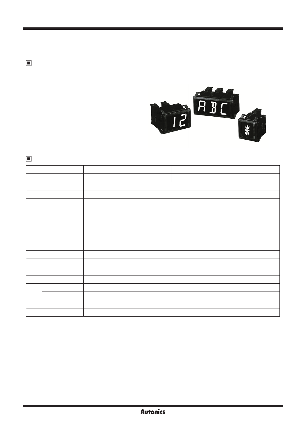
D1AA Series
Small Display Unit for Vivid Display (W11×H22mm) and
Various 61 Characters and Symbols
Features
● Displays 61 types of characters and signs
(0 to 9, A to Z, decimal point, 24 symbols)
● Selectable input logic (PNP/NPN), data input type (parallel/serial)
● 16-segment in red/green
● Wide range of input signal level
: Low: 0-1.2VDC, High: 4.5-24VDC
● 12-24VDC power supply
● Multi-stage connection available
Specifications
~
※
Model D1AA-RN D1AA-GN
Display method 16-segment LED display (red) 16-segment LED display (green)
Power supply 12-24VDCᜡ
'
Allowable voltage range 90 to 110% of rated voltage
Current consumption Max. 32mA
Display character 61 characters (0 to 9, A to Z, decimal point, 24 symbols)
Character size W11×H22mm
Input
'
Input level High: 4.5-24VDCᜡ, Low: 0-1.2VDC
Max. Clock Max. 3kHz
Input resistance 20
Output Data output (serial input)
Input logic Selectable positive (PNP) or negative (NPN) (by inner soldering)
'
Noise immunity ±300V the square wave noise (pulse width: 1μs) by the noise simulator
Ambient temperature 0 to 60℃, storage: -10 to 85
Environ
-ment
Ambient humidity 35 to 85%RH
u
Accessory Connector
'
Unit weight Approx. 22g (including right/left caps)
~
※
1: It is option.
※
Max. Clock is for 1:1 of duty ratio (ON, OFF ratio).
※
Environment resistance is rated at no freezing of condensation.
4
j
j
j
j
j
J
•Parallel: Parallel 6-bit data, latch, decimal point
•Serial: Serial 6-bit or 7-bit data, clock, latch, decimal point (for 6-bit input)
j
j
ᜡ
j
kΩ
J
J
j
j
J
℃
J
j
J
J
l
1
j
~
j
~
~
j
~
R-38
Autonics
16-Segment Display Unit
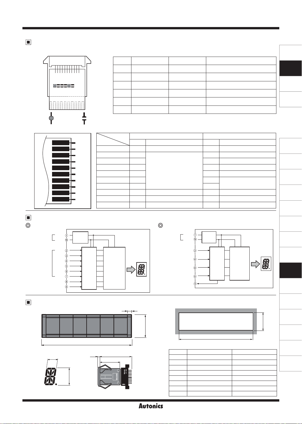
Unit Description
Function set switches
①
Switch ON OFF Function
S1
①
S4 J2 J1 S3 S2 S1
r1
r·1 r·1
r-~
n n
--------
r-1
J.
defaults>
②
r1
n n
※
ON = (short) OFF = (open)
<factory
S2 Parallel Serial Input
S3 7-bit 6-bit Serial input
J1 Use Unused Serial data output
J2
S4 Negative (NPN) Positive (PNP) Input logic
※
T
Input/Output terminals
②
I
10
9
8
7
6
5
4
3
2
)
Block Diagram
~
1
Parallel input Serial input
Power
[
V+
GND
Stablize
power
Terminal
~
1 VCC 12-24VDC VCC 12-24VDC
2 D0
3 D1 CK Clock input
4 D2 DI Data input
5 D3 DO Data output
6 D4 N·C
7 D5 N·C
8 LE Latch input LE Latch input
9 DP Decimal point input DP Decimal point input
10 GND 0V GND 0V
- -
- -
1: For Serial input, set this as ON. For Parallel input, set this as OFF.
Input
Parallel input Serial input
Code Function Code Function
Data input
Power
[
V+
GND
Unused
※
1
Always set as OFF.
N·C Do not connect anything.
e---
Stablize
Do not connect anything.
power
SENSORS
CONTROLLERS
MOTION DEVICES
SOFTWARE
(J)
Temperature
Controllers
(K)
SSRs
(L)
Power
Controllers
(M)
Counters
(N)
Timers
(O)
Digital
Panel Meters
(P)
Indicators
D0
D1
Data input
Decimal point - DP
D2
D3
D4
D5
LATCH - LE
Dimensions
II
I I I I I lf
,____
______
11
Clock input - CK
Data input - DI
Input
circuit
A
22
DECODER
DRIVER
3.5 54
35
Latch inupt - LE
Decimal point - DP
Data output - DO
6
33
~
1
● Panel cut-out
...
j===~~~IJJ
>+-------~'
● Panel cut-out chart
Digit (N) Dimension A (20×N+12) Dimension B (20×N+10)
1 32 30±0.1
2 52 50±0.1
3 72 70±0.1
4 92 90±0.1
F==t======±=====~
5 112 110±0.1
6 132 130±0.1
7 152 150±0.1
8 172 170±0.1
Input
circuit
※
The ②, ⑥, ⑦
B
DECODER
DRIVER
pin are not used.
(unit: mm)
31
Autonics
R-39
(Q)
Converters
(R)
Digital
Display Units
(S)
Sensor
Controllers
(T)
Switching
Mode Power
Supplies
(U)
Recorders
(V)
HMIs
(W)
Panel PC
(X)
Field Network
Devices
~-

D1AA Series
(Q) (Q)
● Connector (model: CT-10S)
7 5
2-Ø3.4
n
7.5
13.5
19
7.5
M
0
...
~~
._,ro
~
0
I
2
y
s
b
1
B
q
i
Ii
t
I
L
-
I
..!
?
...
~"'
...
......
~
...
J
~N
23
D3 D2 D1 D0
L L H L
L L H H
L H L L
L H L H
L H H H
H L L L
H L L H
H L H L
H L H H
H H L L
H H L H
H H H L
H H H H
42
37
32
I
Input Data Chart
~
Upper 2-bit data (PNP type) in positive logic Lower 4-bit data (PNP type) in positive logic
D5 D4 D5 D4 D5 D4 D5 D4
L L L H H L H H
Blank
R
]
r
'Tl
.JJ
E
F
G
H
T
J.
T 7
IJ
f:
I
L
M 1
I I
Ill
I
II
In
u
※
Blank: Even though data is input as signal, it does not display.
p
n I
u
R
r
T
I
I I
u
ti
I I
1111
11
11
11
I
L II
[
I
I
J -
Ill
t
Blank L L L L
Blank L L L H
,,
II 3 L J
~
i
Blank L H H L
I
I
I
I
I
I
+
Ii
-
ii
I
I
Sold separately Accessory
● CAP
Iii
● D1AA-RN: DAR(L)-R (right/left 1 set)
● D1AA-GN: DAR(L)-BL (right/left 1 set)
※
Cap is optional (1 set).
ii
※
In case of positive logic (PNP).
Input Circuit
Positive logic (PNP) input Negative logic (NPN) input
5V
20
kΩ
100
R-40
Input
20
kΩ
100
kΩ
※
Input level
IC
High: 4.5-24VDC
[
Low: 0-1.2VDC
Input
Autonics
kΩ
IC

~
Data Input Method
(Q)
Parallel input
● 6-bit static parallel input (e.g.: displays Auto.)
6-bit Data3+Point3
6-bit Data2+Point2
6-bit Data1+Point1
6-bit Data0+Point0
LATCH
3
10
.~.
10
2
/r
10
1
.;,
0
10
[I [I [I [I
● 6-bit dynamic parallel input (e.g.: displays ACE007.)
3
6-bit Data
Point
LATCH 5
LATCH 4
LATCH 1
LATCH 0
(Q)
Serial input
10
2
10
1
10
0
10
[I] [I] [I] [I]
LATCH 5
LATCH 4
LATCH 3
LATCH 2
LATCH 1
LATCH 0
● 6-bit serial input (e.g.: displays -20.8)
START
t
LATCH
CLOCK
1-bit Data
※
1: For 6-bit Serial input, connect DP of rear input terminal to V+ to display decimal point.
In case of negative logic (NPN), connect DP to GND.
SH FT
H H H H H H H H H H H H
L L L L L L L L L L L L
D3 D3 D3 D3D4 D4 D4 D4D5 D5 D5 D5D2 D2 D2 D2D1 D1 D1 D1D0 D0 D0 D0
MSB (3)
0 33ms
Data Data Data Data
1
[I]
LSB (3)
MSB (2)
[I
LSB (2)
MSB (1)
● 7-bit serial input (e.g.: displays AUTO.)
START
t
LATCH
CLOCK
1-bit Data
SHIFT
L L L L L L L L L L L L L L L L L
D5 D5 D5 D5D3 D3 D3 D3D4 D4 D4 D4D2 D2 D2 D2 D2D1 D1 D1 D1 D1D0 D0 D0 D0 D0 D0
0 33ms
H H H H H H H H H H H
16-Segment Display Unit
6-bit Data3+Point3
6-bit Data2+Point2
6-bit Data1+Point1
6-bit Data0+Point0
LATCH
6-bit
Data
Point
Pw
LLLLLH LLLLHH LLLHLH HHLLLL HHLLLL HHLHHH
t1 t3
t2
10
[I]
3
LLLLLH+L
LHLHLH+L
LHLHLL+L
LLHHHH+H
__
[j]
2
10
※
~ ~ ~
5
1010
※
Clock: Max. 3kHz
※
In case of positive logic (PNP), hexadecimal number
1
~
※
1
1ml
3
10
ta: 0.23ms (Min.)
tw: 0.05ms (Min.)
LSB (1)
MSB (0)
2
10
※
Pw=t1+t2+t3
Pw: 0.33ms (Min.)
t1: 0 05ms (Min.) → Data LATCH
t2: 0 23ms (Min.) → Data move
t3: 0 05ms (Min.) → Data
,----t-7
10
Data input speed: Max. 3kHz
~
1
x=:::::=::>c
x=:::::=::>c
x=:::::=::>c
~
__
'---------'----.-----'---------'
• ! ! •
[I]
[I
1
0
10
~
; i i i i
: I I : :
! i i i :
: : i i
: I i i i
' i i : i
• • t t t t
~
~
~
rmllffillffil~rel
1
10
[I
0
10
tw
~
ta
tttttttttttttttttttttttt
LSB (0)
ta: 0.23ms (Min.)
tw: 0.05ms (Min.)
tw
ta
tttttttttttttttttttttttttttt
SENSORS
CONTROLLERS
MOTION DEVICES
SOFTWARE
(J)
Temperature
Controllers
(K)
SSRs
(L)
Power
Controllers
(M)
Counters
(N)
Timers
(O)
Digital
Panel Meters
(P)
Indicators
(Q)
Converters
(R)
Digital
Display Units
(S)
Sensor
Controllers
(T)
Switching
Mode Power
Supplies
(U)
Recorders
(V)
HMIs
~
(W)
Panel PC
,~,~,~~~~~~-~,~·~·~,~~~~~~-~,~·~·~~\._______A_____\_J\__j\__jl
(X)
Field Network
Devices
Point
Data Data Data Data
MSB (3)
[I]
LSB (3)
Point
MSB (2)
[I]
LSB (2)
Point
MSB (1)
LSB (1)
[i]
s,1uo1ny
Point
MSB (0)
1 1 1 1
[I]
LSB (0)
R-41

D1AA Series
Multi-Stage Connection Method
※
Do wiring after removing the rear case of the product.
Parallel input: 4-digit
● Static parallel input
DP 0
D5
D4
- - -
D3
;,:====: ;,:====:
D2
D1
=
D0
>---
~
0 0 0 0
c-----
10
GND GND GND GND
9
DP DP DP DP
- -
8
LE LE LE LE
7
D5 D5 D5 D5
- -
6
D4 D4 D4 D4
5
- - -
D3 D3 D3 D3
4
D2 D2 D2 D2
-
3
D1 D1 D1 D1
2
DO DO DO DO
- - -
1
V+ V+ V+ V+
- - - -
,-
Q
0
10
● Dynamic parallel input
0 0 0 0
10
GND
9
DP
LE
8
7
D5
6
D4
5
D3
4
D2
3
D1
2
DO
1
V+
0 0 0
0
10
DP 1
D5
D4
D3
D2
;,:====:
D1
D0
>---
~
10
9
8
- -
7
- -
6
5
4
-
3
- -
2
1
~
Q Q
1
10
10
GND GND GND
9
DP DP DP
LE LE LE
8
7
D5 D5 D5
6
D4 D4 D4
5
D3 D3 D3
4
D2 D2 D2
3
D1 D1 D1
2
DO DO DO
1
V+ V+ V+
1
10
DP 2
D5
D4
E
D3
=
D2
'======cc!
D1
~
D0
'--------'
~
~
10
9
8
7
6
5
4
... ...
3
2
1
~
2
10
10
9
8
7
6
5
4
3
2
1
2
10
DP 3
D5
D4
D3
;,:====:
D2
;,:====:
D1
D0
~
~
~
c-----
10
9
8
7
6
...
5
4
3
2
1
,-
Q
3
10
9
7
5
3
1
10
GND
LATCH
V+
LATCH 0
LATCH 1
LATCH 2
LATCH 3
10
8
6
4
2
3
GND
DP
D5
D4
D3
D2
D1
D0
V+
Serial input: 4-digit
0 0 0 0
10
GND
9
DP
8
LE
7
...
6
... ...
5
DO DO DO DO
4
DI DI DI DI
3
CK CK CK CK
2
...
1
V+ V+ V+ V+
0 0 0 0
0
10
R-42
10
9
8
7
... ...
6
5
4
3
2
1
1
10
10
9
8
7
6
...
5
4
3
2
... ...
1
2
10
Autonics
10
DI
(data input)
10
9
8
7
6
5
4
3
2
1
3
GND
LATCH
CK
V+

16-Segment Display Unit
The Application of PLC Program [Serial Input Type]
1. Display unit: D1AA -
2. Data transmission type: Serial input
□
3. Connection method: Refer to serial connection type
when using more than 2.
4. Display result: "A" display
P000
M000
M001
-------1
M000
::
M001
M000
M001
::
M000
-------1
M001
M000
..
M001
-------1
M000
M001
::
M000
S00.13
f------------11-----------i
S00 01
S00 03
"
S00 05
::
S00 07
S00 09
S00.11
..
S00.13
..
S00 02
S00 04
S00 06
S00 08
S00.10
S00.12
PG~
S00 02
S00 04
S00 06
S00 08
S00.10
S00.12
PG~
P000
..
S00 01
S00 02
f-
,:
S00 03
S00 04
f-,: I
S00 05
S00 06
f-,: I
S00 07
S00 08
f-,: I
S00 09
S00.10
f-,: I
S00.11
S00.12
r-
,:
S00.13
--
M015
I
I
M014
I
M013
I
M012
I
M011
I
M010
I
I
5. PLC: LSIS (LS Industrial Systems), Master-K Series
6. When using serial type,
use transistor output card of PLC
7. Negative logic (NPN)
[ SET S00.01 ]
[ SET S00.02 ]
[ SET S00.03 ]
[ SET S00.04 ]
[ SET S00.05 ]
[ SET S00.06 ]
[ SET S00.07 ]
[ SET S00.08 ]
[ SET S00.09 ]
[ SET S00.10 ]
[ SET S00.11 ]
[ SET S00.12 ]
[ SET S00.13 ]
[ SET S00.00 ]
(M000)
(M001)
(P010)
[ MOV h001 M01 ]
(P011)
(P012)
[ END ]
Shift register
Reset
Clock output
HEX "1" value
Transmission order to M01
HEX "1" value data output
"A" display
Latch output
SENSORS
CONTROLLERS
MOTION DEVICES
SOFTWARE
(J)
Temperature
Controllers
(K)
SSRs
(L)
Power
Controllers
(M)
Counters
(N)
Timers
(O)
Digital
Panel Meters
(P)
Indicators
(Q)
Converters
(R)
Digital
Display Units
(S)
Sensor
Controllers
(T)
Switching
Mode Power
Supplies
(U)
Recorders
(V)
HMIs
(W)
Panel PC
(X)
Field Network
Devices
Autonics
R-43
 Loading...