

DRW171143A D
Autonics
Counter/Timer
CT SERIES
I N S T R U C T I O N M A N U A L
CTS SeriesCTY Series
Thank you for choosing our Autonics product.
Please read the following safety considerations before use.
Safety Considerations
Please observe all safety considerations for safe and proper product operation to avoid hazards.
※
symbol represents caution due to special circumstances in which hazards may occur.
※
Failure to follow these instructions may result in serious injury or death.
Warning
Failure to follow these instructions may result in personal injury or product damage.
Caution
Warning
1. Fail-safe device must be installed when using the unit with machinery that may cause
serious injury or substantial economic loss. (e.g. nuclear power control, medical equipment,
ships, vehicles, railways, aircraft, combustion apparatus, safety equipment, crime/disaster
prevention devices, etc.)
Failure to follow this instruction may result in re, personal injury, or economic loss.
2. Install on a device panel to use.
Failure to follow this instruction may result in electric shock or re.
3. Do not connect, repair, or inspect the unit while connected to a power source.
Failure to follow this instruction may result in electric shock or re.
4. Check ‘Connections’ before wiring.
Failure to follow this instruction may result in re.
5. Do not disassemble or modify the unit.
Failure to follow this instruction may result in electric shock or re.
Caution
1. When connecting communication, the power/sensor input and relay output, use
AWG 20(0.50mm
0.74 to 0.90N.m.
Failure to follow this instruction may result in re or malfunction due to contact failure.
2. Use the unit within the rated specications.
Failure to follow this instruction may result in re or product damage.
3. Use dry cloth to clean the unit, and do not use water or organic solvent.
Failure to follow this instruction may result in electric shock or re.
4. Do not use the unit in the place where ammable/explosive/corrosive gas, humidity,
direct sunlight, radiant heat, vibration, impact, or salinity may be present.
Failure to follow this instruction may result in re or explosion.
5. Keep metal chip, dust, and wire residue from owing into the unit.
Failure to follow this instruction may result in re or product damage.
Manual
For the detail information and instructions, please refer to user manual and user manual for
communication, and be sure to follow cautions written in the technical descriptions (catalog, homepage).
2
) cable or over, and tighten the terminal screw with a tightening torque of
CTM Series
1----------------------i~
Ordering Information
~
CT 2P64 TM
LJ
I
tem
-
Size
Display digits
Output
Communication
Power supply
No-mark None
T RS485 communication output
2 24VAC 50/60Hz, 24-48VDC
4 100-240VAC 50/60Hz
1P 1-stage preset
2P 2-stage preset
※
1
I
Indicator
S D N W48×H48mm
Y D N W72×H36mm
M D N W72×H72mm
4 9999 (4-digit)
6 999999 (6-digit)
CT Counter/Timer
※
1:
CT4S model does not support indicator type.
1---------------------,~
Unit Description
CTS Series
1
6
3
7
8
9
CTY Series
0
7
4
5
3
1. Counting value display component (red)
2. Setting value display component (yellow-green)
3. Key lock indicator (LOCK) Turns ON for key lock setting.
4. Counter indicator (CNT) Turns ON for counter operation.
5. Timer indicator (TMR) Flashes (progressing time) or Turns ON (stoping time) for timer operation.
6. Preset value checking and changing indicator (PS1, PS2)
7. Output indicator (OUT1, OUT2) Turns ON for the dedicated control output ON.
8.
9.
10.
11. key
12. BATCH output indicator (BA.O) (red)
13. BATCH preset value checking and changing indicator (BA.S) (yellow-green)
612
RUN mode
: Displays counting value for counter operation
or time progress value for timer operation.
Function setting mode: Displays setting item.
RUN mode: Displays setting value.
Function setting mode: Displays setting content.
Turns ON when checking and changing preset value.
key
~
RUN mode: Press the
BATCH counter mode: Press the
key
~
RUN mode: Hold the
Function setting mode: Press the key to select function setting mode parameter.
III~~
1)
2) , key
~
RUN mode: Press the
Turns ON when checking and changing BATCH preset value.
Hold the key over 5 sec. to enter function setting mode(communication setting).
key
,
key
~
RUN mode: Press the key to enter preset mode.
Preset mode: Press the key to move preset digits.
Iii
l1il
RUN mode: Hold the key over 1 sec. to enter Function setting check mode.
Preset mode: Used for increasing or decreasing preset value.
Function setting mode: Changes the settings.
Function setting check mode: Press the key to move the previous parameter.
2
5
4
10
8
10
9
key to reset the counting value.
~
key over 3 sec. to enter function setting mode(parameter setting).
IMDI
IMO
Hold the key over 3 sec. to return RUN mode.
~
~
key to reset the batch counting value.
~
~
MD
l1il
I!!]
Press the key to the next parameter.
l1il
key to enter BATCH counter indication mode.
~
Connections
CTS Series
0
CT□S-1P
•
12VDC 100mA
INB / INH
INA
CT□S-2P
•
12VDC 100mA
INB / INH
INA
OUT1
250VAC 5A, 30VDC 5A
CT6S-I
• •
12VDC 100mA
INB / IN
INA
0
CT6Y-1P
• •
INA
INB / INH
12VDC 100mA
CT6Y-2P
• •
INA
INB / INH
12VDC 100mA
CT6Y-I
• •
INA
INB / INH
12VDC 100mA
※
The above specifications are subject to change and some models may be discontinued
without notice.
Be sure to follow cautions written in the instruction manual, user manual and the technical
※
descriptions (catalog, homepage).
□
※
2
RESET
6172839410
NO
250VAC 5A, 30VDC 5A
RESISTIVE LOAD
※
6172839410
RESISTIVE
0VDC
OUT
COM
5
NC
※
□
2
RESET
0VDC
OUT2
5
※
□
※
2
H
6172839410
CTY Series
250VAC 3A, 30VDC 3A
RESET
0VDC
5
※
□
RESISTIVE LOAD
NC COM NO
819210311412513
OUT
※
2
□
NC COM OUT
819210311412513
OUT2
※
2
RESET0VDC
250VAC 3A, 30VDC 3A
RESISTIVE LOAD
NO
OUT1
RESET0VDC
□
1 2 3 4 5 6 7
※
2
RESET0VDC
1211
1
1211
1
1211
1
STATE OUT
OUT
30VDC
100mA
OUT2
30VDC
100mA
SOLID
30VDC
100mA
6 7
6 7
OUT
※
1
SOLID
STATE OUT
30VDC
100mA
OUT2
※
1
※
1
CTM Series
B.B.B.B.B.B
6
13
3
7
8
Model Changed Note
CT4S-1P
CT6S-1P
CT6Y-1P
CT6M-1P
CT6S-I
CT6Y-I
CT6M-I
※
Be sure that connection is varied by
supporting RS485 communication.
CT□S-1P□T
•
12VDC 100mA
INB / INH
INA
250VAC 5A, 30VDC 5A
CT□S-2P□T
12VDC 100mA
INB / INH
INA
CT6S-I□T
12VDC 100mA
INB / INH
INA
CT6Y-1P□T
INA
INB / INH
12VDC 100mA
CT6Y-2P□T
INA
INB / INH
12VDC 100mA
CT6Y-I□T
INA
INB / INH
12VDC 100mA
11
PS2→PS
OUT2→OUT
PS2→PS
CT4S model does not support indicator type.
※
2
6172839410
RS485
A(+) B( )
OUT
COM
NO
RESISTIVE LOAD
※
2
6172839410
A(+)
RS485
OUT1
OUT2
250VAC 5A, 30VDC 5A
RESISTIVE
※
2
6172839410
RS485
A(+) B( )
250VAC 3A, 30VDC 3A
RESISTIVE LOAD
NC COM NO
819210311412513
OUT
※
2
250VAC 3A, 30VDC 3A
RESISTIVE
819210311412513
OUT2 OUT1
※
2
819210
※
2
10
9
There are no
PS1, OUT1 LEDs
There are no
PS1, OUT1, OUT2,
BA.S, BA.O LEDs,
key.
l
ieAi
RESET
0VDC
1211
5
NC
※
1
RESET
0VDC
B( )
1211
5
※
1
RESET
0VDC
1211
5
※
1
SOLID
STATE OUT
30VDC
A(+) B( )
100mA
RS485
OUT
6 7
RESET0VDC
A(+) B( )
RS485
6 7
RESET0VDC
A(+) B( )
RS485
3114125136 7
RESET0VDC
1
2
5
4
12
※
1
※
1
※
1
Specications
Series
1-stage preset CT4S -1P
I
2-stage preset
Model
I
I
Indicator
Display digits 4-digit 6-digit 6- digit 6-digit
Display method 7 segment (c ounting val ue: red, set ting value: ye llow-g reen) LED metho d
Counting value 6.5×10m m 4.5×10 mm 4.2× 9.5mm 6.6×13mm
I
Character
size(W×H)
I
Setting value 4.5×8mm 3. 5×7m m 3 .5 ×7mm 5×9 mm
I
AC voltag e 100 -240VACᜠ 50/60Hz
Power
supply
AC/DC vol tage 24VACᜠ 50/60Hz, 24-48VDC
I
Permissible voltage range 90 to 110% of rated vo ltage
I
AC voltag e Ma x. 12VA
Power
consumption
I
AC/DC vol tage AC: ma x. 10VA, DC: ma x. 8W
INA/ NB
Max. co unting spe ed
Counting range -999 to 9999 -99999 to 999999
Scale
Counter
Min. signal width RE SET signa l: selectable 1ms/20ms
I
4-digit 9 999s, 99 99s, 999.9s, 9999s, 99m59s, 999.9m, 9999m, 99h59m, 9999h
Time
range
6-digit
Operation method Count up, Count down, Count Up/Down
Min. signal width IN A, NH , RESET sig nal: selec table 1ms/2 0ms
Timer
Repeat error
Set error
Voltage error
Temp. error
Input method
One- shot outpu t time 0.01s to 99.9 9s setti ng
--
-
Contac t
output
Solid st ate
output
Control output
(NPN open
collector)
Exter nal power su pply Max. 12VDCᜡ ±10%, 100 mA
Memory retention Approx. 10 years (non-volatile memory)
Insulation resistance Over 100 MΩ (at 500VD C megger)
Dielectric strength 2,000VAC 50 /60Hz fo r 1 min.
Noise
immunity
Vibration
Shock
Relay life
cycle
Protection structure IP65 (f ront par t, IEC stan dard)
Environ-
mental
Approval
Weight
※
1: The weight includes packaging. The weight in parenthesis is for unit only.
Environment resistance is rated at no freezing or condensation.
※
Communication Specications
Interface
Comm. protocol Modbus RTU with 16-bit CRC
Connection type RS485
Application standard Compliance with EIA RS485
Max. connection 31 units (address: 1 to 127)
Comm. type Two-wire half duplex
Synchronous method Asynchronous
Comm. distance Max. 800m
Comm. speed 2400, 4800, 9600(factory default), 19200, 38400bps
Comm. response time 5 to 99ms (factory default: 20ms)
Start bit 1-bit (xed)
Data bit 8-bit (xed)
Parity bit None(factory default), Even, Odd
Stop bit 1, 2-bit (factory default: 2-bit)
※
It is recommended to use Autonics communication converter; SCM-WF48 (Wi-Fi to RS485 USB wireless
communication converter, sold separately), SCM-US48I (USB to RS485 converter, sold separately), SCM-38I
(RS232C to RS485 converter, sold separately).
※
Please use twisted pair wire, which is suitable for RS485 communication, for SCM-WF48, SCM-US48I and
SCM-38I.
Dimensions
CTS Series
0
CTY Series
0
Capacity
Capacity Max. 30VD Cᜡ, 100m A
AC voltag e Square-wave no ise by noise s imulator (p ulse widt h 1㎲) ±2kV
AC/DC vol tage Square- wave noise by no ise simula tor (pulse w idth 1㎲) ±500V
Mechanical
Malfunction
Mechanical 30 0m/s² (approx. 30 G) in each X, Y, Z direc tion for 3 ti mes
Malfunction 100m/s ² (approx. 10G) in e ach X, Y, Z directi on for 3 time s
Mechanical Min. 10,000,000 operations
Malfunction Min. 100,000 operations
I
Ambient temp. -10 to 55℃, storage: - 25 to 65
Ambient humi. 35 to 85%RH, storage: 35 to 8 5%RH
I
※
1
48
□
72
l•IJ
CTM Series
□
11
2 3 tj 5.15
:I 123~5.Sl
Cl
• 9
Cl
ID
CXJOOI
Bracket Panel cut-out
0
CTS Series CTS Series
•
48.3 15
0
CTS CTY CTM
CT4 S- 2P
-
Selectable 1cps/30cps/1kcps/5kcps/10kcps
Decimal point
up to third d igit
999.999s, 9999 99s, 99999.9s, 999999s, 99m59 99s, 999m59.9s, 9999m59s,
99999.9m, 999999m, 99h59m59s, 9999h59m, 99999.9h
In case of p ower ON sta rt: max. ± 0.01% ±0 05s
In case of s ignal star t: max. ±0.01% ±0.03 s
Select able volt age input (P NP) or no-vo ltage inp ut (NPN)
[Volta ge input] -input imp edance: 5. 4kΩ, [H]: 5 -30VDCᜡ, [L]: 0-2 VDC
[No- voltage in put]- s hort- circuit i mpedanc e: max. 1kΩ,
Standard Comm. Standard Comm. Standard Comm.
-
1-stage
SPDT(1c): 1 S PDT(1c): 1 SPDT(1c): 1
I
2-stage
SPS T(1a): 2 SPST(1a), SPDT(1c): 1
I
Typ e
250 VACᜠ 5A, 30V DCᜡ 5A
resistive load
1-stage
1
2-stage
Typ e
f-
0.75mm ampl itude at fre quency of 10 to 5 5Hz (for 1 min.) in ea ch X, Y, Z
direct ion for 1 hou r
0.5mm am plitude at f requency o f 10 to 55Hz (for 1 m in.) in each X, Y, Z
direction for 10 minutes
CE,"1,.
Approx. 212g
(approx. 159g)
1
o o
26.345.8
.
CT6S -1P
□□
CT6S-2P
□ □
CT6S-I CT 6Y- I CT6M-I
Decima l point up to f ifth dig it
-
~
6 77
36
~-
: :
10 8572
CT 6Y-1 P CT6M -1P
□ □
□□
□□ □□
short-circuit residual voltage: max. 2VDC
□ □
CT 6Y-2 P CT6M-2P
□ □
I
I
ᜡ
250 VACᜠ 3A, 30 VDCᜡ 3A
resistive load
1
℃
Approx. 228g
(approx. 140g)
9010
n : c~ ,:
0
==
==
==
==
=
=~
0
•
[
Min. 62
I
1 2
I
-
I
45
30.2
H
67
□
Min. 55
EBEE:
□
□
□□
□□
INA, R ESET, INHIB IT,
BATCH RESET si gnal:
selectable 1ms/20ms
ᜡ
I
SPST(1a): 1, SPDT(1c): 1
250 VACᜠ 5A, 30V DCᜡ 5A
resistive load
3
Approx. 322g
(approx. 252g)
I
2
I
(unit: mm)
0
+0.6
45
EB
60.2
CTY Series
•
4
I
'
•
12
: I
CTM Series
•
□
.
0
z:,£3
60
TI
9
Li
~
~
68 4.4
10
l!C
l
14.5
CTY Series
Min. 40
CTM Series
•
Min. 91
+0.7
68
0
Min. 91
◄
►
D D,I
Min. 91
12
52
{
CTM Series
0
.
CT6M-1P
12VDC 100mA
INB
INA
• •
12VDC 100mA
INB
INA
12VDC 100mA
INB
INA
※
1: AC Voltage: 100-240VAC 50/60Hz
※
2: Counter operation: If INHIBIT signal is applied, count input will be prohibited.
□
8
OUTPUT
COMMON
15
192103
CT6M-2P
□
8
OUTPUT
COMMON
15
OUT1
192103
250VAC 5A, 30VDC 5A
RESISTIVE LOAD
CT6M-I
□
8
15
192103
AC/DC Voltage: 24-48VDC, 24VAC 50/60Hz
Timer operation: If INH BIT signal is applied, time progressing will stop (HOLD)
※
2
INHIBIT
RESET
0VDC
11
SOLID STATE OUT
OUT BATCH
16
OUT
4
250VAC 5A, 30VDC 5A
RESISTIVE LOAD
※
2
INHIBIT
RESET
0VDC
11
SOLID STATE OUT
OUT1 OUT2 BATCH
16
OUT2
4
※
2
INHIBIT
RESET
0VDC
11
16
4
12
5
NCCOMNO
12
5
NCCOMCOM NONO
12
5
131714
30VDC
100mA
18
131714
30VDC
100mA
18
131714
18
6 7
6 7
6 7
BATCH RESET
※
BATCH RESET
※
※
Input Logic Selection
CTS Series
①
Turn OFF the power before
changing input logic (PNP/NPN)
CTS CTY
0
No-voltage input(NPN)
NPN NPN
PNP PNP
SW1
※
How to change settings
Power OFF → change settings → power ON → press key or input signal (min. 20ms)
1. The power must be cut off.
2. Squeeze toward ① and pull toward ② as the gure.
①
Voltage input(PNP)
(CTS/CTY Series)
3. Select input logic by using input logic switch (SW1) inside
②
Counter/Timer.
4. Push a case in the opposite direction of ②.
5. Then supply the power to counter/timer.
No-voltage input(NPN)
NPN NPN
PNP PNP
1
1
1
CT6M-1P□T
•
12VDC 100mA
INB
INA
8
192103
CT6M-2P□T
12VDC 100mA
INB
INA
8
OUT1
192103
250VAC 5A, 30VDC 5A
RESISTIVE LOAD
CT6M-I□T
12VDC 100mA
INB
INA
8
192103
Voltage input(PNP)
SW1
※
2
INHIBIT
RESET
0VDC
11
RS485
15
16
A(+) B( )
SOLID STATE OUT
OUT
4
250VAC 5A, 30VDC 5A
RESISTIVE LOAD
INHIBIT
RESET
0VDC
11
RS485
15
16
A(+)
B( )
SOLID STATE OUT
OUT2
4
INHIBIT
RESET
0VDC
RS485
15
16
A(+) B( )
CTM
0
Voltage input(PNP) No-Voltage input(NPN)
PNP PNPNPN NPN
12
OUT BATCH
30VDC
100mA
5
NCCOMNO
※
2
12
18
OUT2 BATCH
5
NCCOM COMNO NO
※
2
11
12
4
5
SW1
BATCH RESET
131714
18
6 7
BATCH RESET
131714
30VDC
100mA
6 7
131714
18
6 7
※
※
Basic Operations
(Counter/Timer/Communication)
1. Operations and functions
BATCH
RESET
BATCH counter
※
1
Change
of BATCH
setting value.
1: If no key is touched for 60 sec.,
※
the counter will return to RUN mode
without being restored.
1-1. Change of preset (Counter/Timer)
Even if changing the preset value, input operation and output control will continue. In addition, the
preset value could be set to 0 and the ouput of 0 preset value turns ON. According to the output
mode, preset value could not be set to 0. (When setting to 0, preset value "0" will ash 3 times.)
In RUN mode, press the key
to enter preset mode. 'PS1'
indicator turns ON and rst digit
of preset value ashes.
1-2. Function setting check mode
Setting value of function setting mode can be conrmed using the and keys.
1-3. Switching display function in preset indicator
Setting value 1(PS1) and setting value 2(PS2) are displayed each time pressing key in dual
preset model. (In timer, it is available for
1-4. Reset
In RUN mode or function setting mode, if pressing key or applying the signal to the RESET
terminal on the back side, present value will be reset and output will maintain off status.
-CT S: Short no. 8 and 10 terminals for voltage input (PNP), short no. 9 and 10 terminals for non-voltage input (NPN).
□
-CT6Y: Short no. 3 and 5 terminals for voltage input (PNP), short no. 4 and 5 terminals for non-voltage input (NPN).
-CT6M: Short no. 10 and 12 terminals for voltage input (PNP), short no. 11 and 12 terminals for non-voltage input (NPN).
2. Flow chart for function setting mode
....
.....
.......
....
Counter
[
COUN
Input mode
[IN]
Output mode
[
OUt M
Indication mode
[
DSp M
※1
Max. counting speed
[
OUT2 output time
[
OUT2
OUT1 output time
[
OUT1
Decimal point
[DP]
Min. reset time
[
Function setting mode
................ :@l .............................. ................................................................. ......... .
※
If changing Parameter group1 setting value, display value and output are reset.
※
Parameter 2 group is not available to non-communication models.
Timer Mode
1. Parameter setting
Parameter Setting
Counter/Timer
[
C T
Time range
[
HOUR/MIN
SEC
Up/Down mode
[
U D
0
+0.5
Indication mode
[
31.5
DSpM
Memory
protection
[
DATA
Output mode
[
OUtM
OUT2
output time
[
OUT2
0
+0.7
OUT1
68
output time
[
OUT1
OUT
output time
[
OUtT
Input logic
[
SIG
Input signal
time [
Key lock
[
LOCK
※
1: When output mode is
does not appear. The output time of
When output mode is
※
2:
INt2
2. Timer '0' time setting
2-1. Timer output mode for '0' time setting [
2-2. Operations by output mode ('0' time setting)
1
1
※
A. OND (Signal ON Delay) mode [
Set '0' for setting time 1.
NA (START)
Setting time 2
B. OND.1 (Signal ON Delay 1) mode [
Set ‘0’ for setting time 1.
NA (START)
Setting time 2
C. OND.2 (Power ON Delay) mode [
Set ‘0’ for setting time 1.
POWER
RESET
Setting time 2
1
D. NFD (ON-OFF Delay) mode [
Set '0' for Off_Delay setting time.
UP
DISPLAY
DOWN
E. NFD.1 (ON-OFF Delay1) mode [
Set ‘0’ for Off_Delay setting time.
UP
DISPLAY
DOWN
RST
Input logic
[
SI G
Prescale decimal
point
[
ScDP
Prescale value
[
SCL
Start Point value
[
STRT
Memorize
counting value
[
DATA
Lock key
[
LOCK
]
/
]
]
]
]
]
※
1
]
※
1
]
※
1
]
]
]
InT
]
mode is available only for 2-stage preset model.
····
0
OUT 1
_
OUT 2
RESET
0
OUT 1
OUT 2
---,-
······
0
OUT 1
OUT 2
-
INA (START)
RESET
On_Delay
On_Delay
OUT 2 (OUT)
INA (START)
RESET
On_Delay
On_Delay
OUT 2 (OUT)
indication mode
※
3sec. 3sec. 5sec. 3sec.
...........
:@J
Parameter group1
I I,
]
Counter/Timer
]
※
1
]
]
CPS
]
]
]
]
]
]
]
]
]
COUN
-
6-digit type
•
0 001s to
999.999s
•
HOUR
9999(9
~
0.1h to
99999.9h
•
.
1m to
9999h59m
4-digit type
•
er
0 001s to
9 999s
•
UP
DN
-
TOTAL
- -
•
※
Used for the indicator type only.
※
It is added that the feature which set the setting time when selecting
CLR
-
OND ONd1 ONd2 FLK FLk1 FLk2 INT
- - - - - -
INTG
L
※
Set one-shot output time of OUT2.
※
Setting range: 00.01 to 99.99sec., Hold.
※
When 1st digit is ashing, press the
※
Set one-shot output time of OUT1.
※
Setting range: 00.01 to 99.99sec., Hold.
※
When 1st digit is ashing, press the
※
Setting range: 00.01 to 99.99sec., Hold.
※
When 1st digit is ashing, press the
: No-voltage input,
NPN
※
Check input logic value(PNP, NPN).
1
20
--------.
unit: ms
lOFF
-
t t
LOc3 LOc2
-
FLk1, FLk2, INTG
OND, ONd1, ONd2, INt2, OUT1
Up mode
r::=:7
77
c::b
__,
h~
Up mode
□
□
Up mode
- - P P
!zn
r::t:J
----
□~
7 P F
0
0
fi
PP
0
0
RESET
RUN
BATCH counter is
available for CT6M-1P/2P
model only.
Function 3sec. Enters into parameter 1 group
setting mode
Press the
set the desired value (example,
180
enter the PS2 setting mode.
, and keys to
). Press the
OND, ONd1
RUN mode
I 1 :@] ...........
[
]
GRp1
[
]
C T
※
※
※
※
-
TIME
I I
999(9999(999 9999(9 999999 995(99
J I
I I
I I
99h59m59s
SECSEC SEC
9(99(999 99(9
0 01s to
99 99s
L_J
►
1h to
9999h
HOLD ONtD
Timer
[
TIME
Time range
[
HOUR/MIN/SEC
2
Up/Down mode
[
U D
Indication mode
[
DSpM
Memorize
counting value
[
DATA
Output mode
[
OUtM
IMQ]
OUT2 output time
[
OUT2
~
OUT1 output time
[
OUT1
~i
Input logic
[
SIG
IMQ]
+
Input signal time
[
InT
IMQ]
+
Lock key
[
LOCK
IMQ]
I
1: Indicator
2: Output type
When changing the setting of shaded parameters,
all output turn OFF. When returning RUN mode,
PV is reset.
MD
key: Moves the settings,
(
□
SECSEC SEC SEC M S
I
I
0.01s to
9999.99s
I
I
1s to
~
0.1s to
999 9s
''
- -
1m to
99h59m
※
UP
DN
mode
3sec.
5sec.
3sec.
5sec. Enters into parameter 2 group
key to
or
output mode.)
ONd2
...
......
...
.....................
§]
~
·I I i
]
]
]
※
1
]
]
]
]
]
]
---
]
]
:
Counter
COUN
※
: Timer
TIME
0.1s to
99999.9s
1m to
999999m
9999
n
9999m
: Time progresses from ‘0’ to the setting time.
: Time progresses from the setting time to ‘0’.
SEC
1s to
9999s
1m to
999999s
1
..
9999(9999999995959999959
I
0.1m to
99999.9m
M S
9959
99m59s
•
•
MI NMINH MHOUR
,,
L_J
99(9999999599999
0.1m to
999.9m
•
※
Used for the indicator type only.
※
REC
-
※
,
※
LOc1
One-shot output (0.01 to 99.99 sec.)
Retained output
OND
·····=··
···
·
=s::
NFD
NFd1
: Reset time value when power is off.
CLR
: Memorizes time value at the moment of power off.
REC
NFd1 NFD OFD INt2 INt1
CTS/CTY: Set min. width of INA, NH, RESET signal.
CTM: Set min. width of INA, RESET, INHIBIT, BATCH RESET
※
lOFF
LOc1
LOc2
LOc3
]
Down mode
r::=:7
- -
-
key once and
I!]
key once and
I!]
key once and
I!]
: Voltage input
PNP
signal.
: Unlock keys, key lock indicator turns OFF
: Locks
OUT2
: Locks
: Locks
key, key lock indicator turns ON
~
, , keys, key lock indicator turns ON
I!]~§]
, , , keys, key lock indicator turns ON
~
IIl~
and
OND, ONd1, ONd2
is displayed as
OND, ONd1, ONd2, NFD, NFd1
§l
.
OUtT
appears.
Set ‘0’ for setting time 2.
NA (START)
Setting time 1
·r
b
h
]
ONd1
Down mode
□□
ONd2
Down mode
]
····
r
h
□
tJ
]
]
Set ‘0’ for On_Delay setting time.
UP
DISPLAY
DOWN
Set ‘0’ for On_Delay setting time.
F 9 9
UP
DISPLAY
DOWN
OUT 1
OUT 2
Set ‘0’ for setting time 2.
NA (START)
RESET
Setting time 1
OUT 1
OUT 2
Set ‘0’ for setting time 2.
POWER
RESET
Setting time 1
OUT 1
OUT 2
INA (START)
RESET
Off_Delay
Off_Delay
OUT 2 (OUT)
INA (START)
RESET
Off_Delay
Off_Delay
OUT 2 (OUT)
※
1
Preset mode
1sec.
Function setting
1sec.
check mode
Press the
set the desired value (example,
200
return RUN mode.
, and keys to
). Press the
~
11 .~ .........
Parameter group2
[
Communication
Comm. address
[
ADDR
Comm. speed
[
Comm. parity
[
PRTY
Comm. stop bit
[
IMQ_
Response
waiting time
[
RSwT
~ i
Comm. writing
[
COmW
IMQ_
key: Changes the settings)
GRp2
BPS
STP
t
key to
...
.. .
]
]
]
]
]
]
]
I
I
1s to
MINMINH M SH M
1s to
of 1-stage preset model,
One-shot output
0.01s to
99m59.99s
M S
•
9995(9
0.1s to
999m59 9s
t
M S
...
,
999959
1s to
9999m59s
HOLD
•
-
appears.
HOLD
appears.
HOLD
appears.
HOLD
]
------:--------------:---
0
I
J
I
or
ONtD
OUT1
Retained output
r:::::::j
p
□
D
0
t::::::J
Up mode
□
······i··············i···
0
t::::::J
0
9 P
0
~
0
dti
ri
ri
d
F7
0
0
r:---j
t:::::::J
Counter Mode
1. Parameter setting
Parameter Setting
Counter/
Timer [
C T
Input mode
[IN]
Output mode
[
]
OUtM
Indication
mode
[
]
DSpM
Max. counting
speed
[
]
CPS
OUT2
output time
[
]
OUT2
OUT1
output time
[
]
OUT1
OUT
output time
[
]
OUtT
Decimal
2
※
point
[DP]
Min. reset
time [
RST
Input logic
[
]
SIG
Prescale
decimal
2
※
point
[
]
ScDP
Prescale
value [
SCL
Start point
value
[
]
STRT
Memory
protection
[
]
DATA
Key lock
[
]
LOCK
※
1:
For 1-stage preset model,
※
2: Decimal point and prescale decimal point
- Decimal point: Set the decimal point for display value regardless of prescale value.
- Prescale decimal point: Set the decimal point for prescale value of counting value regardless of
2. Input mode
Input mode
UP
[Up]
UP 1
[Up-1]
UP 2
[Up-2]
DN
[Down]
DN 1
[Down-1]
DN 2
[Down-2]
UD A
[Up/
Down-A]
1
※
UD B
[Up/
Down-B]
1
※
UD C
[Up/
Down-C]
※
1:
For selectable no-voltage input (PNP) ,
voltage input (NPN) model.
A: over min. signal width, B: over than 1/2 of
※
min. signal width. If the signal is smaller than
these width, it may cause counting error (±1) .
※
The meaning of "H", "L"
Input method
Character
f---
1 ····--
.. ___
H 5-30VDC Short
L 0-2VDC Open
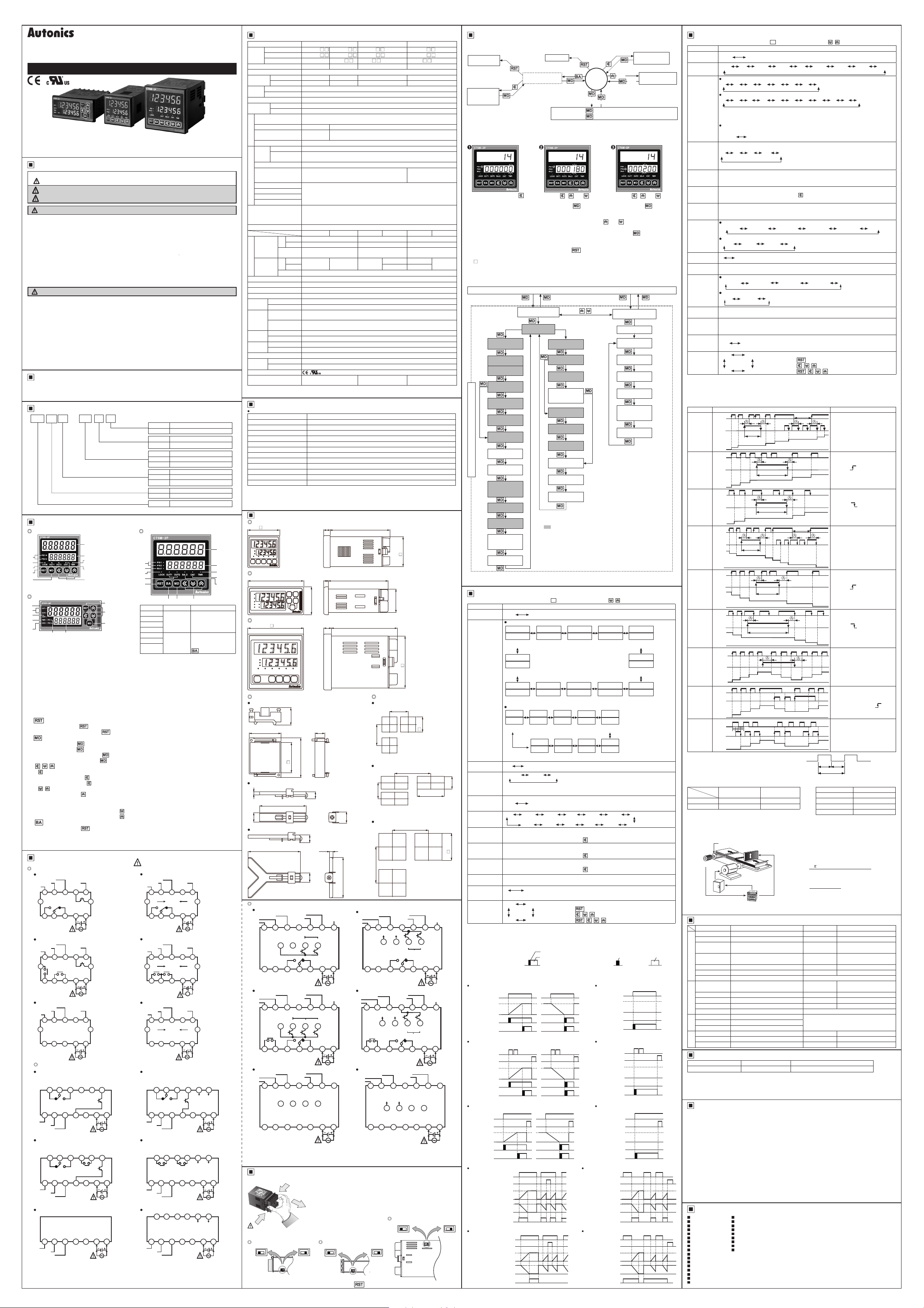
3. Prescale function
This function is to set and display calculated unit for actual length, liquid, position, etc. t is called
“prescale value” for measured length, liquid, or position, etc per 1 pulse. For example, when moving L,
the desired length to be measured, and P, the number of pulses per 1 revolution of a rotary encoder,
occurs, prescale value is L/P.
E.g.) Positioning control by counter and encoder
Rotary encoder
Motor control system
Set decimal point[DP] as [
as [0.
] at function setting mode. It is available to control conveyer position by 0.1mm unit.
069
+-+
COUN
]
UD C
.
•
.
•
※
.
type
30
+ +
※
1
※
※
※
※
1
※
※
※
※
1
※
※
6-digit type
•
4-digit type
•
•
1
]
NPN
※
6-digit type
•
4-digit type
•
※
]
※
※
CLR
lOFF
LOc3 LOc2
Counting chart Operation
INA
INB
Count
INA
INB
Count
INA
INB
Count
INA
INB
Count
0
INA
INB
Count
INA
INB
Count
INA
INB
Count
INA
INB
0
Count
INA
INB
Count
Voltage input
(PNP)
--+--
__ · I
Pulley
TIME
UP
- - -
-
•
Input mode is
N [ R K P Q A
F
----
Input mode is
N [ R K P Q A S T D
F
----------
If max. counting speed is 5kcps, and output mode is D, max. counting speed is
automatically changed as 30cps, factory default.
In case of the indicator
HOLD TOTAL
+-+
1K 5K 10K 1
--- -
Set one-shot output time of OUT2.
Setting range: 00.01 to 99.99sec.
When input mode is F, N, S, T, D,
Set one-shot output time of OUT1. ※Setting range: 00 01 to 99.99sec., Hold.
When 1st digit is ashing, press the
When input mode is S, T, D,
Setting range: 00.01 to 99.99sec.
When input mode is F, N, S, T, D,
. . . . .
-
•
.
. .
- -
, unit: ms
20
-
: No-voltage input,
Check input logic value (PNP, NPN).
.
+
-
. . .
!
-
Setting range of prescale value
6-digit type: 0.00001 to 99999 9, 4-digit type: 0.001 to 999.9
Setting range (linked with decimal point [DP]):
6-digit type: 0.00001 to 999999, 4-digit type: 0.001 to 9999
When input mode is DN,
.........
REC
LOc1
-
t t
-
decimal point of display value.
H
L
H
L
No counting
1
0
H
L
□n□ e
H
L
:1r r~
2
1
0
H
L
□
□
H
L
1
_____r-
0
H
L
H
L
No counting
n
--LJ
..__..
n-1
n-2
H
L
H
L
n
n-1
n-2
0
H
L
H
L
n
n-1
0
H
L
H
L
2
1
0
~
H
L
nnn,----:,
H
' ' i
L
2
~
1
H
L
H
L
~
0
---+------,
Motor
MD
key: Moves the settings,
(
□
※
COUN
UP 1 UP 2 DN DN 1 DN 2 UD A UD B
UP, UP 1, UP 2
UD A, UD B, UD C
--
※
In case of the indicator type, indicate mode selection
[
DSpM
※
t is the added function to set the preset value when
selecting
-
-
: Voltage input
PNP
. . . .
-
-
♦
DN 1, DN 2
※
: Resets the counting value when power OFF.
CLR
: Maintains the counting value when power OFF.
REC
(memory protection)
※
: Unlock keys, key lock indicator turns OFF
lOFF
LOc1
: Locks
LOc2
: Locks
LOc3
does not appear. The output time of
OUT1
4
3
2
□
No counting
3
D
□□
No counting
2
n-3
n-4
--,____;
No counting
n-3
No counting
n-2
4
3
3
□
4
3
.
3
3
22
No-voltage input
(NPN)
Cutter
Counter
], prescale decimal point [
-
or DN,
DN 1, DN 2
,
] is displayed.
HOLD
※
Max. counting speed is when duty ratio of NA or
INB input signal is 1:1. It is applied for INA, or INB
input as same.
※
When output mode is D, set max. counting speed
one among 1cps, 30cps, or 1kcps.
OUT2
key once and
<I
does not appear. (xed as HOLD)
OUT1
OUtT
-
※
Set min. width of external reset signal input.
-
, start point value does not appear.
: Locks
~
, keys, key lock indicator turns ON
I!] ~
1
RSTn«rn
No counting
5
□
4
P
3
No counting
n-5
-
n-6
n-4
n-3
2
1
□
t7
t:::::::t::::,
2 2
:
11
INA
H
(INB)
L
I
[ Diameter (D) of pulley connected with
encoder= 22mm, the number of pulses by
1 rotation of encoder=1,000]
Prescale value
*
=
=
=
[§!I
[!'jJ
, key: Changes the settings)
Counter
:
: Timer
TIME
- -
,
-
•
.
does not appear. (xed as HOLD)
HOLD
does not appear. (xed as HOLD)
-
appears.
- -
※
Decimal point is applied to counting
value and setting value.
-.
※
ecimal point of prescale should not
D
set smaller than decimal point [DP].
key, key lock indicator turns ON
§I
,
~
, keys, key lock indicator turns ON
※
7
6
f7
※
5
※
※
※
4
※
※
※
n-7
※
※
※
n-5
※
※
※
n-4
n-5
※
※
4
3
2
□□
µ--
___f7_____f7__
※
※
4
3
※
3
2
~
ON
T.on
T.off
"I
...
T
※
Min. signal width by counting speed
Counting speed Min. signal width
1cps 500ms
t-----
1
30cps 16.7ms
1kcps 0.5ms
5kcps 0.1ms
× Diameter (D) of pulley
)C
The number of pulses by 1
rotation of encoder
3.1416 × 22
1000
0.069mm/pulse
] as [
ScDP
is displayed as
OUT2
When NA is counting input,
NB is no counting input.
When INB is counting input,
NA is no counting input.
When NA input signal is
rising ( ) , it counts.
INA: Counting input
INB: No counting input
When NA input signal is
falling ( ) , it counts.
L
INA: Counting input
INB: No counting input
When NA is counting input,
INB is no counting input.
When INB is counting input,
NA is no counting input.
When NA input signal is
r
rising ( ) , it counts.
INA: Counting input
INB: No counting input
When NA input signal is
falling ( ) , it counts.
"1..
INA: Counting input
INB: No counting input
INA: Counting input
NB: Counting command
input
When NB is "L", counting
command is up.
When INB is "H", it is
counting command is down .
INA: Up counting input
INB: Down counting input
When NA and NB input
signals are rising (
the same time, it maintains
previous counting value.
When connecting encoder
output A, B phase with
counter input, INA, NB, set
input mode [
different input [
counter operation.
.
N.M
I
] as phase
UD C
ONOFF OFF
"
T.on, T.off: Min. signal width
__,______,
], prescale value [
r
Factory Default
Parameter Factory default Parameter Factory default
IN UD C RST 20
OUtM F SIG NPN
DSpM TOTAL ScDP
CPS 30 SCL
Counter
OUtT
(
OUT2
OUT1 0)10 DATA CLR
HOUR/MIN/SEC
DSpM TOTAL SIG NPN
Timer
DATA CLR InT 20
OUtM OND
LOCK lOFF
PS1
PS2
General
ADDR 001 STP 2
Com.
PRTY NONE COmW ENA
) Hold (xed)
DP
U D UP OUT1 0)10
BPS 96 RSWT 20
6-digit typ e:
4-digit type:
1000
5000
0.001
0.001
-
999.999
s
-
9.999
s
STRT 000000
s
OUT2
s
OUtT
(
6-digit type:
4-digit type:
6-digit type:
4-digit type:
)
HOLD
.
.
1.00000
1.000
Error Display and Output Operation
Error Display Error description Troubleshooting
ERR0
※
When error occurs, the output turns OFF.
※
When 1st setting value is set as 0 (zero), OUT1 maintains OFF.
When 2nd setting value is smaller than 1st setting value, 1st setting value is ignored and only
OUT2 output operates.
※
Indicator model does not have error display function.
Cautions during Use
1. Follow instructions in ‘Cautions during Use’. Otherwise, t may cause unexpected accidents.
2. 24-48VDC, 24VAC power supply should be insulated and limited voltage/current or Class 2, SELV
power supply device.
Use the product, 0.1 sec after supplying power.
3.
4. When supplying or turning off the power, use a switch or etc. to avoid chattering.
5. Install a power switch or circuit breaker in the easily accessible place for supplying or disconnecting the
power.
6. In case of contact input, set count speed to low speed mode (1cps or 30cps) to operate.
If set to high speed mode (1k, 5k, 10kcps), counting error occurs due to chattering.
7. Keep away from high voltage lines or power lines to prevent inductive noise.
In case installing power line and input signal line closely
wire at input signal line.
Do not use near the equipment which generates strong magnetic force or high frequency noise.
8. This product may be used in the following environments.
①
Indoors (in the environment condition rated in ‘Specications’)
②
Altitude max. 2,000m
③
Pollution degree 2
④
Installation category II
l-~--------------------1
Major Products
Photoelectric Sensors Temperature Controllers
Fiber Optic Sensors Temperature/Humidity Transducers
Door Sensors SSRs/Power Controllers
Door Side Sensors Counters
Area Sensors Timers
Proximity Sensors Panel Meters
Pressure Sensors Tachometer/Pulse (Rate) Meters
Rotary Encoders Display Units
Connector/Sockets Sensor Controllers
Switching Mode Power Supplies
Control Switches/Lamps/Buzzers
I/O Terminal Blocks & Cables
Stepper Motors/Drivers/Motion Controllers
Graphic/Logic Panels
Field Network Devices
Laser Marking System (Fiber, CO₂, Nd: YAG)
Laser Welding/Cutting System
Setting value is 0. Change the setting value anything but 0.
, use line lter or varistor at power line and shielded
■
■
■
■
■
■
■
■
■
DR W17114 3 A D
OUtT
) at
] for
+
SCL
.
]
 Loading...