

DRW171149AD
Autonics
MULTI FUNCTION TIMER
AT11DN/AT11EN SERIES
I N S T R U C T I O N M A N U A L
t---CE_c'i\l_us
Please read the following safety considerations before use.
Safety Considerations
00
Please observe all safety considerations for safe and proper product operation to avoid hazards.
※
symbol represents caution due to special circumstances in which hazards may occur.
※
Warning
~1
i ---------ll
Caution
Warning
b.
1. Fail-safe device must be installed when using the unit with machinery that may cause serious injury
or substantial economic loss. (e.g. nuclear power control, medical equipment, ships, vehicles,
railways, aircraft, combustion apparatus, safety equipment, crime/disaster prevention devices, etc.)
Failure to follow this instruction may result in personal injury, economic loss or fire.
2. Do not use the unit in the place where ammable/explosive/corrosive gas, humidity, direct sunlight,
radiant heat, vibration, impact, or salinity may be present.
Failure to follow this instruction may result in explosion or re.
3. Install on a device panel to use.
Failure to follow this instruction may result in fire or electric shock.
4. Do not connect, repair, or inspect the unit while connected to a power source.
Failure to follow this instruction may result in fire or electric shock.
5. Check 'Connections' before wiring.
Failure to follow this instruction may result in fire.
6. Do not disassemble or modify the unit.
Failure to follow this instruction may result in fire or electric shock.
Caution
1. Use the unit within the rated specications.
Failure to follow this instruction may result in re or product damage.
2. Use dry cloth to clean the unit, and do not use water or organic solvent.
Failure to follow this instruction may result in fire or electric shock.
3. Keep metal chip, dust, and wire residue from owing into the unit.
Failure to follow this instruction may result in re or product damage.
Ordering Information
AT
11 DN
1
Number of plug pins
Item
※
11-pin socket (PG-11, PS-11(N)) is sold separately.
Unit Description
00
Operation/Power indicator
(Flashes for timer operation,
Turns ON for timer stop)
Time range indication
Time range setting switch
Output operation mode indicator
(sec, min, hour, 10h mode)
Connections
00
. .
AT11DN SERIES AT11EN SERIES
RESET
START
INHIBIT
(Time limit
1c)
※
1: AC/DC voltage: 100-240VAC 50/60Hz, 24-240VDC
: 24VAC 50/60Hz, 24VDC
DC voltage: 12VDC
※
The above specications are subject to change and some models may be discontinued
without notice.
※
Be sure to follow cautions written in the instruction manual and the technical descriptions
(catalog, homepage).
Thank you for choosing our Autonics product.
----------1
Failure to follow these instructions may result in serious injury or death.
Failure to follow these instructions may result in personal injury or product damage.
Time Specications
-
Power
supply
Time operation
7
7
5
4
3
2
1
100-240VAC 50/60Hz,
No mark
24-240VDC
1 12VDC
2 24VAC 50/60Hz, 24VDC
DN Time limit 2c
Instantaneous 1c
EN
+ Time limit 1c
11 11-pin plug type
AT Analog Timer
CONTACT OUT:
250VAC 5A,
24VDC 5A
6
7
RESISTIVE LOAD
8
9
10
11
(Time limit 1c)
※
1
Time limit output
indicator
Output operation
mode indicator
(A, F, F1,
C, D,
Output operation
mode setting SW
(Instantaneous
1c)
Time range Time unit
0.5
1.0 0.1 to 1 sec.
5 0.5 to 5 sec.
10 1 to 10 sec.
0.5
f-----------+----------j
1.0 0.1 to 1 min.
5 0.5 to 5 min.
10 1 to 10 min.
0.5
1.0 0.1 to 1 hour
5 0.5 to 5 hour
10 1 to 10 hour
0.5
1.0 1 to 10 hour
5 5 to 50 hour
mode)
10 10 to 100 hour
RESET
START
INHIBIT
6
5
4
3
2
1
sec
min
hour
10h
11
7
8
9
10
CONTACT OUT:
250VAC 5A,
30VDC 5A
RESISTIVE LOAD
Time setting range
0.05 to 0.5 sec.
0.05 to 0.5 min.
0.05 to 0.5 hour
0.5 to 5 hour
(Time limit 1c)
※
1
Dimensions
48 6.5
i
30.5
36
~
44.9
48.6
45
Li
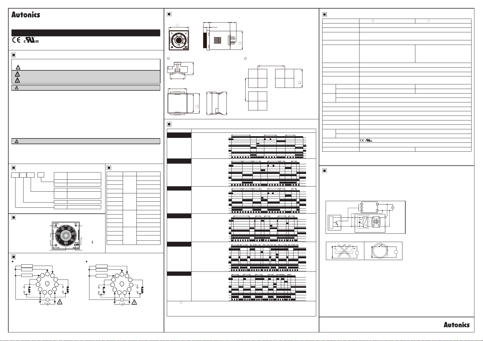
Output Operation Mode
00
Mode Time chart
A
Signal ON Delay
F
Flicker
(OFF Start)
F1
Flicker 1
(ON Start)
C
Signal OFF Delay
D
Signal ON/OFF
Delay
I
Interval
※AT11EN- model only supports
If power is cut or the RESET terminal is short-circuited, the timer will be RESET.
※
If the INHIBIT terminal is short-circuited during a time limit operation, the time will stop.
※
In case of F, F1 output operation mode, setting time should be over 100ms.
※
If not, it may cause abnormal output operation due to under 100ms of setting time.
□
□
!
5014.9 14.7
44.8
~
Panel cut-out Bracket
Min. 65
55
[[[
Power 2-10
START 2-6
INHIBIT 2-5
RESET 2-7
Time limit contact N.C.
Time limit contact N.O.
Instantaneous contact N.C.
Instantaneous contact N.O.
Time limit output indicator
Operation/Power indicator
Power 2-10
START 2-6
INHIBIT 2-5
RESET 2-7
Time limit contact N.C.
Time limit contact N.O.
Instantaneous contact N.C.
Instantaneous contact N.O.
Time limit output indicator
Operation/Power indicator
Power 2-10
START 2-6
INHIBIT 2-5
RESET 2-7
Time limit contact N.C.
Time limit contact N.O.
Instantaneous contact N.C.
Instantaneous contact N.O.
Time limit output indicator
Operation/Power indicator
Power 2-10
START 2-6
INHIBIT 2-5
RESET 2-7
Time lim t contact N.C.
Time limit contact N.O.
Instantaneous contact N.C.
Instantaneous contact N.O.
Time limit output indicator
Operation/Power indicator
Power 2-10
START 2-6
INHIBIT 2-5
RESET 2-7
Time lim t contact N.C.
Time limit contact N.O.
Instantaneous contact N.C.
Instantaneous contact N.O.
Time limit output indicator
Operation/Power indicator
Power 2-10
START 2-6
INHIBIT 2-5
RESET 2-7
Time limit contact N.C.
Time limit contact N.O.
Instantaneous contact N.C.
Instantaneous contact N.O.
Time limit output indicator
Operation/Power indicator
Instantaneous contact.
56
l
l...l.l.B..116
3
-
BIi
_,
t t1 t2
...
__
t t t t1 t2t-a
t t t t1 t2t-a
..
il
..
t
-------------
-------------
t t t
t t t
EE
.l
il:
Min. 65
[t: Setting time, t=t1+t2, t>t-a]
□
t-a t-a
t1t2t-a
El
..
l.R
t2
t1
t-a
t-a t-a
t1 t2t-a t-a
(unit: mm)
0
+0.6
45
□
Specications
00
Model AT11DN-
Function Multi Function Timer
Control time setting range
Power supply
Allowable voltage range 90 to 110% of the rated voltage
Power consumption
Return time Max. 100ms
Time operation Signal ON Start
Min. input signal width START, RESET, INHIBIT: approx. 50ms
Input
Contact type Time limit DPDT (2c)
Control
output
Contact capacity 250VACᜠ 5A, 24VDC 5A resistive load 250VACᜠ 5A, 30VDC 5A resistive load
Mechanical Min. 10,000,000 operations
Relay
life cycle
Electrical Min. 100,000 operations (250VAC 5A resistive load)
Repeat error Max. ±0.2% ±10ms
Setting error Max. ±5% ±50ms
Voltage error Max. ±0.5%
Temperature error Max. ±2%
Insulation resistance 100MΩ (at 500VDC megger)
Dielectric strength 2,000VAC 50/60Hz for 1 minute
Ambient temp. -10 to 55℃, storage: -25 to 65
Environment
Ambient humid. 35 to 85%RH, storage: 35 to 85%RH
Approval
Accessory Bracket
2
※
Weight
※
1: Refer to time specications for control time setting range by model.
※
2: The weight includes packaging. The weight in parenthesis is for unit only.
※
Environment resistance is rated at no freezing or condensation.
□ □
1
※
0.05 sec. to 100 hour
•100-240VACᜠ 50/60Hz, 24-240VDC universal •24VACᜠ 50/60Hz, 24VDC universal
• 12VDC
•Max. 3.5VA (100-240VAC
Max. 1.5W (24-240VDC )
•Max. 4VA (24VACᜠ),
Max. 1.5W (24VDC )
•Max. 1W (12VDC )
START, RESET, INHIBIT: [No-voltage input] - Short-circuit impedance: max. 1kΩ,
Residual voltage: max. 0.5VDC, Open-circuit impedance: max. 100kΩ
CE
,'ill.
Approx. 132.2g (approx. 85g) Approx. 134.7g (approx. 87.5g)
) ,
ᜠ
℃
AT11EN-
•Max. 4.3VA (100-240VACᜠ) ,
Max. 2W (24-240VDC )
•Max. 4.5VA (24VACᜠ),
Max. 2W (24VDC )
•Max. 1.5W (12VDC )
Instantaneous SPDT (1c)+Time limit SPDT (1c)
Cautions during Use
1. Follow instructions in 'Cautions during Use'. Otherwise, it may cause unexpected accidents.
2. 12VDC, 24VDC, 24VAC power supply should be insulated and limited voltage/current or Class 2, SELV power
supply device.
3. When supplying or turning o the power, use a switch or etc. to avoid chattering.
4. Install a power switch or circuit breaker in the easily accessible place for supplying or disconnecting the power.
5. In order to block peripheral current, use isolation transformer which of secondary part is not grounded as (Figure 1)
to supply power to the external input device.
(Figure 1)
< Sensor >
Main circui
6. In order to avoid leakage current owing, connect resistance and condenser as (Figure 3).
If connect as (Figure 2), it may cause malfunction due to leakage current.
(Figure 2) (Figure 3)
Leakage
current
Power
R C
7. Do not connect two or more timers with only one input contact or transistor simultaneously.
8. Keep away from high voltage lines or power lines to prevent inductive noise.
In case installing power line and input signal line closely, use line lter or varistor at power line and shielded wire at
input signal line.
Do not use near the equipment which generates strong magnetic force or high frequency noise.
9. Change setting time, time range, operation mode or etc. after turning o the power of the timer.
10. This unit may be used in the following environments.
Indoors (in the environment condition rated in 'Specications')
①
Altitude max. 2,000m
②
Pollution degree 2
③
Installation category II
④
START
RESET
INHIBIT
Rectication
circuit
Timer
T
Power
Isolation
transformer
Power
<External sensor
power supply>
R
C
T
Timer
Autonics
 Loading...