

AS Series
Rectangular, Long Sensing Distance Type Proximity Sensor
Features
● Sensing up to as 50mm
● Improved the noise immunity with dedicated IC
● Built-in reverse polarity protection circuit,
surge protection circuit,
output short over current protection circuit
● Wide range of power supply: 12-48VDC
(voltage range: 10-65VDC)
● Simultaneous output of Normally Open+Normally Closed
● Built-in power indicator and operation indicator
● IP67 protection structure (IEC standard)
Please read “Safety Considerations”
in the instruction manual before using.
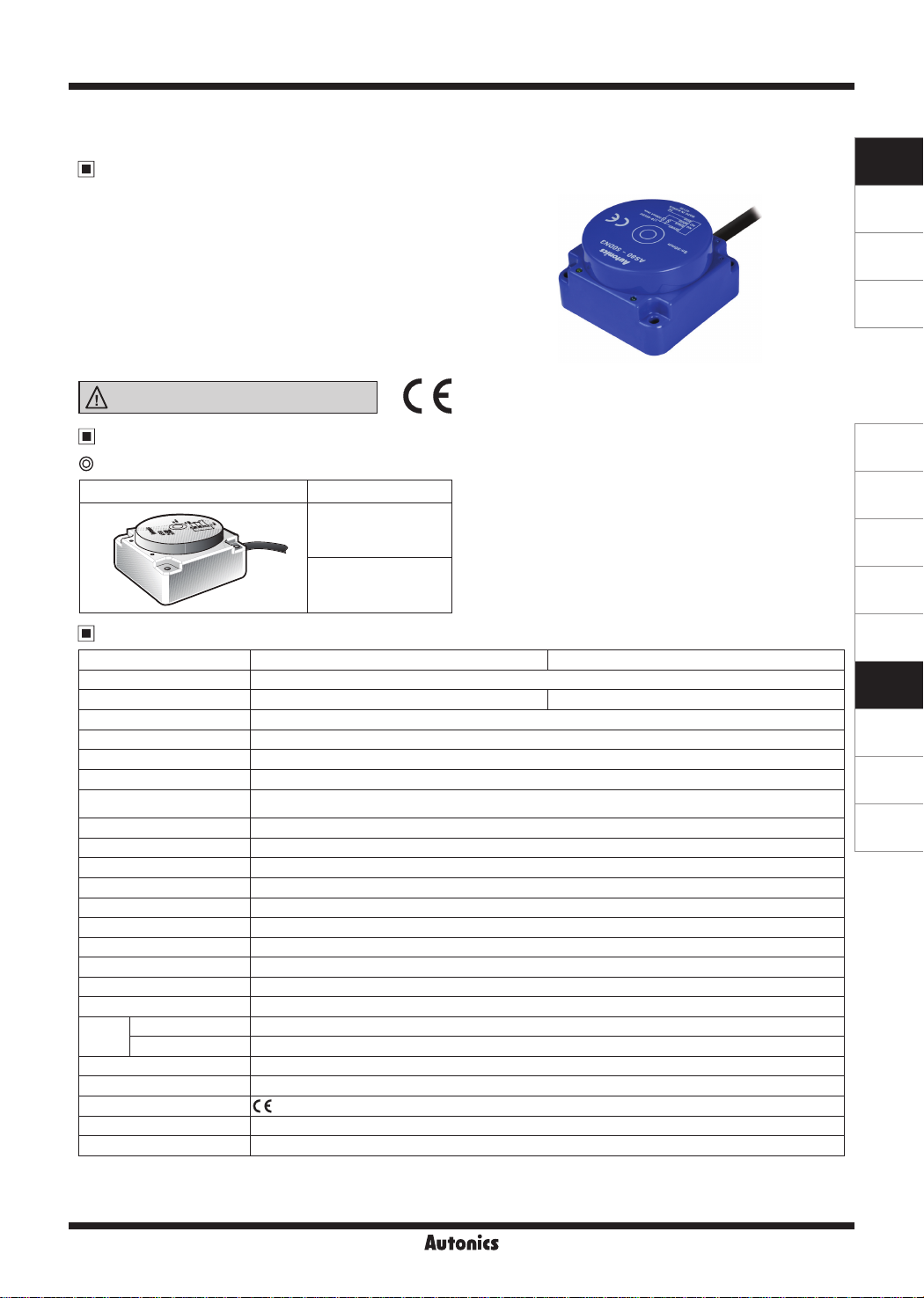
Type
DC 4-wire long distance type
Appearance Model
AS80-50DN3
CE
SENSORS
CONTROLLERS
MOTION DEVICES
SOFTWARE
(A)
Photoelectric
Sensors
(B)
Fiber Optic
Sensors
(C)
LiDAR
AS80-50DP3
Specification
Model AS80-50DN3 AS80-50DP3
Sensing side Upper side
Sensing type NPN Normally Open + Normally Closed PNP Normally Open + Normally Closed
Sensing distance 50mm
Hysteresis Max. 15% of sensing distance
Standard sensing target 150×150×1mm (iron)
Set ing distance 0 to 35mm
Power supply
(operating voltage)
Current consumption Max. 20mA
Response frequency
Residual voltage Max. 2V
Aection by Temp.
Control output Max. 200mA
Insulation resistance Over 50MΩ (at 500VDC megger)
Dielectric strength 1,500VAC 50/60Hz for 1 min
Vibration 1mm amplitude at frequency of 10 to 55Hz (for 1 min) in each X, Y, Z direc ion for 2 hours
Shock 500m/s² (appox. 50G) in X, Y, Z direction for 3 times
Indicator Power indicator: Green LED, Operation indicator: Yellow LED
Ambient temperature -25 to 70℃, storage: -30 to 80
Environ-
I
ment
Ambient humidity 35 to 95%RH, storage: 35 to 95%RH
I
Protection circuit Surge protection circuit, reverse polarity protection circuit, output short over current protection circuit
Cable Ø5mm, 4-wire, 2m (AWG22, Core diameter: 0.08mm, Number of cores: 60, Insulator diameter: Ø1.25mm)
Approval
Protection structure IP67 (IEC standard)
Unit weight Approx. 470g
※
1: The response frequency is the average value. The standard sensing target is used and the width is set as 2 times of the standard
sensing target, 1/2 of the sensing distance for he distance.
※
Environment resistance is rated at no freezing or condensation.
※
12-48VDCᜡ
(10-65VDCᜡ)
1
30Hz
Max. ±10% for sensing distance at ambient temperature 20℃
℃
CE:
I
I
(D)
Door/Area
Sensors
(E)
Vision
Sensors
(F)
Proximity
Sensors
(G)
Pressure
Sensors
(H)
Rotary
Encoders
(I)
Connectors/
Connector Cables/
Sensor Distribution
Boxes/ Sockets
Autonics
F-173
AS Series
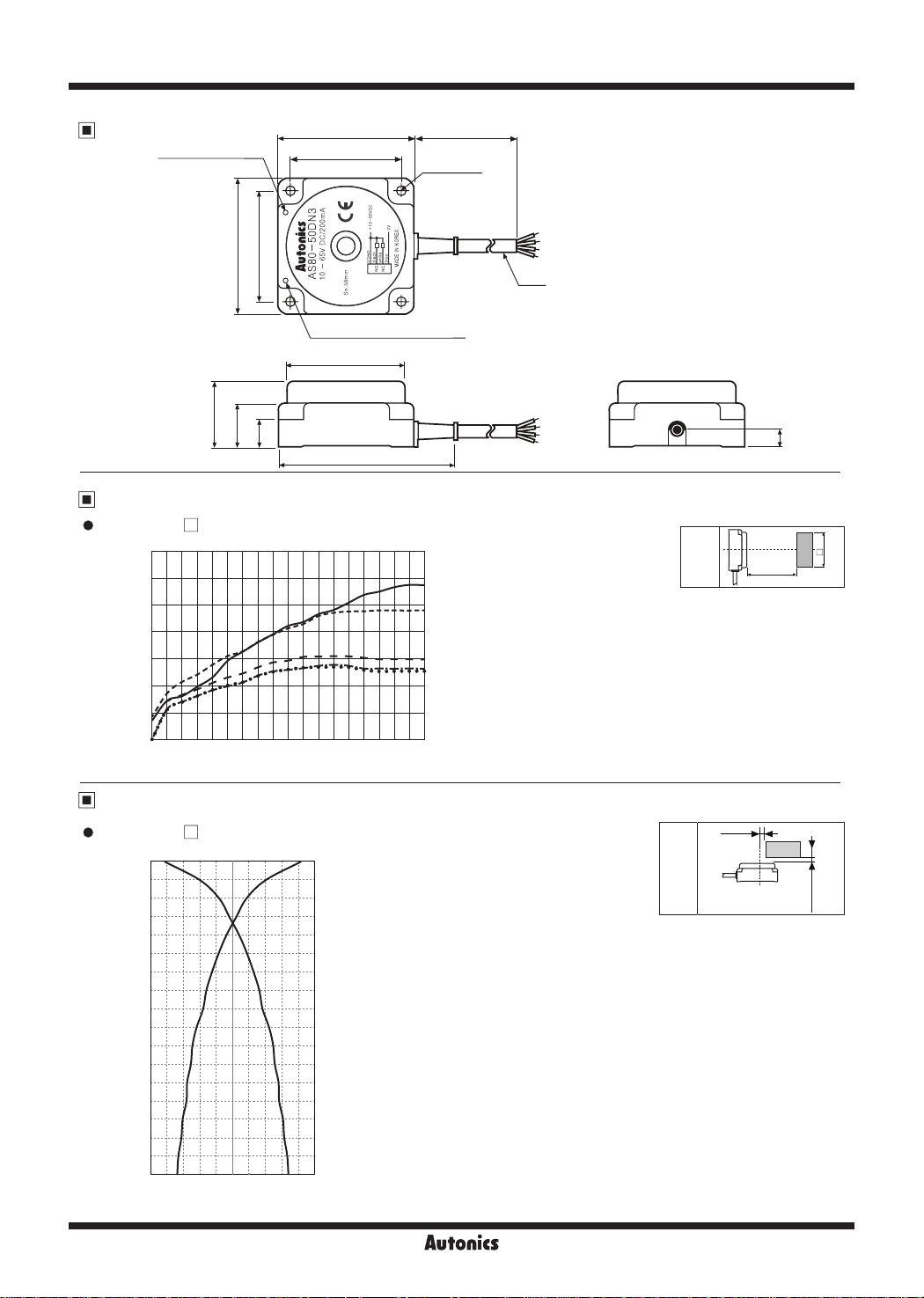
Dimensions
Operation indicator
(yellow LED)
lliE_5
80
65
65
80
Power indicator (green LED)
Ø74
45
30
20
_i------,]r--
102
2000
4-Ø5 5
Ø5
R
~
Sensing Distance Feature Data by Target Material and Size
AS80-50D
70.00
60.00
50.00
40.00
30.00
20.00
Sensing distance X (mm)
10.00
□
r
r
~
-
,...,...,--
r"""
..
I";-
,i-;:
LI.I
'l
0.00
4 8 10 12 15 18 20 25 30 35 40 45 50 60 70 75 80 90 100
• !'"
"V
.
One side length of sensing target d (mm)
.
. .
.
.
r.
-
-
-
.
..
•
..--~
- -
.
Iron (SS401)
Stainless steel 364
(SUS364)
Brass (C3601)
Aluminum (ALS052)
•
Copper (C1100)
Detecting
Method
I
(unit: mm)
11
Sensing
I~
distance (X)
d
target
length
Sensing
One side
_rn
I
Sensing Distance Feature Data by Parallel (Left/Right) Movement
AS80-50D
•
Sensing distance X (mm)
F-174
50.0
49.0
46.0
43.0
40.0
37.0
34.0
31.0
28.0
25.0
22.0
19.0
16.0
13.0
10.0
□
7.0
4.0
1.0
50.0 40.0 30.0 20.0 10.0 0.0 10.0 20.0 30.0 40.0 50.0
Left ← Center → Right
Sensing area Y (mm)
Autonics
Detecting
Method
Sensing
area (Y)
Sensing
target
Sensing
distance (X)

Rectangular, Long Sensing Distance Type
Control Output Diagram and Load Operation
~
47k
Ω
NPN
(N.O.+N.C.)
Main circuit
PNP
(N.O.+N.C.)
Main circuit
47kΩ47k
Proper Usage
~
@
Mutual-interference
47k
Brown
Black
White
Blue
Brown
Black
White
Blue
Load
N.O
N.C.
Load
Ω
Ω
N.C.
N.O.
Load
Load
+V
Sensing
Operation
indicator
(yellow LED)
(brown-black)
(black-blue)
0V
+V
Sensing
Operation
indicator
(yellow LED)
(black-blue)
voltage
0V
(black-blue)
target
Load
Output
voltage
target
Load
Output
Presence
[
None
ON
[
OFF
Operation
[ n
Return
H
[
L
Presence
[ n
None
ON
[
OFF
Operation
[
Return
H
[
L
N.O.
n
D
N.O.
n
D
Sensing
target
Operation
indicator
(yellow LED)
Load
(brown-white)
Output
voltage
(white-blue)
Sensing
target
Operation
indicator
(yellow LED)
Load
(white-blue)
Output
voltage
(white-blue)
Presence
[
None
ON
[
OFF
Operation
[
Return
H
[
L
Presence
[
None
ON
[
OFF
Operation
[
Return
H
[
L
When several proximity sensors are mounted close to one another a malfunction of the sensor may be caused due to
mutual interference. Therefore, be sure to provide a minimum distance between the two sensors as below chart indicates.
N.C.
D
D
D
N.C.
D
D
(unit: mm)
SENSORS
CONTROLLERS
MOTION DEVICES
SOFTWARE
(A)
Photoelectric
Sensors
(B)
Fiber Optic
Sensors
(C)
LiDAR
(D)
Door/Area
Sensors
(E)
Vision
Sensors
320
(Face to Face)
320
(Parallel)
Influence by surrounding metals
When sensors are mounted on metallic panel, you must prevent the sensors from being affected by any metallic object
except target. Therefore, be sure to provide a minimum distance as below chart indicates.
(unit: mm)
150
80 80
Metal
Earth-plate
(F)
Proximity
Sensors
(G)
Pressure
Sensors
(H)
Rotary
Encoders
(I)
Connectors/
Connector Cables/
Sensor Distribution
Boxes/ Sockets
Autonics
F-175
 Loading...