

DRW171436AA
Autonics
DeviceNet Analog Remote I/O
Standard Terminal Block Type
ARD SERIES
I N S T R U C T I O N M A N U A L
(only for ARD-A 04,
other models are
compatible)
Please read the following safety considerations before use.
Safety Considerations
Please observe all safety considerations for safe and proper product operation to avoid hazards.
※
※
symbol represents caution due to special circumstances in which hazards may occur.
Warning Failure to follow these instructions may result in serious injury or death.
Caution
Warning
1. Fail-safe device must be installed when using the unit with machinery that may cause serious
injury or substantial economic loss. (e.g. nuclear power control, medical equipment, ships,
vehicles, railways, aircraft, combustion apparatus, safety equipment, crime/disaster prevention
devices, etc.)
Failure to follow this instruction may result in re, personal injury, or economic loss.
2.
Do not disassemble or modify the unit.
Failure to follow this instruction may result in re.
3.
Do not connect, repair, or inspect the unit while connected to a power source.
Failure to follow this instruction may result in re.
4.
Check 'Connections' before wiring.
Failure to follow this instruction may result in re.
Caution
1.
Use the unit within the rated specications.
Failure to follow this instruction may result in re or product damage.
Use dry cloth to clean the unit, and do not use water or organic solvent.
2.
Failure to follow this instruction may result in electric shock or re.
3.
Do not use the unit in the place where ammable/explosive/corrosive gas, humidity, direct
sunlight, radiant heat, vibration, impact, or salinity may be present.
Failure to follow this instruction may result in re or explosion.
4. Keep metal chip, dust, and wire residue from owing into the unit.
Failure to follow this instruction may result in re or product damage.
5.
Do not disconnect terminal or power, when the product is operating.
Failure to follow this instruction may result in re or malfunction.
Model
Model Network Digital/Analog Input/Output Input/Output point
ARD-AI04
ARD-AO04 Output
DeviceNet Communication
tem Specication
Communication
Communication distance
Node address Max. 64 nodes
Communication speed
Insulation
Approval
The communication speed is automatically set to the communication speed of the Master (PC,
※1.
PLC, etc.) When changing the communication speed during operation, the network status (NS) LED
ashes in red and communication is not possible.
The above specications are subject to change and some models may be discontinued
※
without notice.
Be sure to follow cautions written in the instruction manual, user manual, and
※
the technical descriptions (catalog, homepage).
Thank you for choosing our Autonics product.
Failure to follow these instructions may result in personal injury or product damage.
DeviceNet Analog
I/O Slave messaging (Group 2 only slave)
Poll command: Yes Bit_strobe command: Yes
Cyclic command: Yes COS command: Yes
Max. 500m (125 kbps),
Max. 250m (250kbps),
Max.100m (500 kbps)
125 kbps 250 kbps
※1
500 kbps(automatically set when connecting with master)
I/O and inner circuit: Non-insulated,
DeviceNet and inner circuit: insulation, Power of DeviceNet: insulation
ARD-AI04 : DeviceNet conformance
ARD-AO04 : DeviceNet compatible
Input
4-point
Specications
Model ARD-AI04 ARD-AO04
Power supply Rated voltage: 24VDCᜡ, Voltage range: 12-28VDC
Power consumption Max. 3W
Output points
Voltage
Current
Control
Max. allowable
/O
control I/O
Resolution 14-bit, 1/16,000
Accuracy
Insulation resistance Min. 200MΩ (at 500VDC megger)
Noise resistance ±500V the square wave noise(pulse width: 1㎲) by the noise simulator
Dielectric strength
Vibration
Shock 500m/s
Ambient temp. -10 to 50℃, storage: -25 to 75
I
Environment
Ambient humi. 35 to 85%RH, storage: 35 to 85%RH
I
Protection structure IP20(IEC standard)
Protection circuit Surge, ESD protection, Reverse polarity protection circuit
Indicator
Material Front case, Body Case: PC
Mounting DIN rail or screw lock type
Insulation type
Approval
1
※
Weight
※
1: The weight includes packaging. The weight in parentheses is for unit only.
※
Environment resistance is rated at no freezing or condensation.
Unit Description
2
1
2. Rotary switch for node address
3. Status LED
4. Rail lock
5. DIP switch
~
0-5VDC
1-5VDC
0-10VDC
-
-
DC4-20mA
DC0-20mA
※
6. I/O terminal block
~
6
Two rotary switches are used for setting node address.
X10 switch represents the 10's multiplier and X1 switch represents the 1's multiplier.
It displays the status of unit (MS) and network (NS).
t is used for holding DIN rail and fixing screw holes.
Set the range of I/O.
(Factory default: All switches are OFF)
ARD-AI04 (input model) ARD-AO04 (output model)
/O range
5-5VDC
10-10VDC
1: Turn ON SW8 and I/O range can be set by D P switch(SW1 to SW6). Turn OFF SW8 and I/O range can be
t connects /O with external devices.
CH0, CH1 CH2, CH3 CH0, CH1 CH2, CH3
SW1 SW2 SW3 SW4 SW5 SW6 SW1
set by communication.
By DIP switch, CH0 and CH1(CH2 and CH3) cannot be set separately. By communication, each CH can be
set.
Dimensions
4 points of input
(enables to switch voltage/current)
0-10VDCᜡ, -10-10VDCᜡ,
0-5VDCᜡ, 1-5VDCᜡ, -5-5VDC
(input impedance: min. 1MΩ)
DC 4-20mA, DC0-20mA
(input impedance: 250Ω)
±5% for rated output range
At room temperature (25±5
Out of room temperature ranges: ±0.6% F.S.
500VAC 50/60Hz for 1 minute (between external terminals and case, between
output terminals and power terminals)
1.5mm amplitude at frequency of 10 to 55Hz (for 1 min.) in each X, Y, Z direction
for 2 hours
2
(approx. 50G) in each X, Y, Z direction for 3 times
Network status (NS) LED: Green, Red
Unit status (MS) LED: Green, Red
I/O and inner circuit: non-insulated, DeviceNet and inner circuit: insulated,
Power of DeviceNet: insulated
, , DeviceNet compatible
CE:
De"1c:eNe~
Approx. 210g (approx. 145g)
3
4
(iffl~
ON
- -
- - - - - - -
-
-
•
-
•
• •
- -
-
•
-
•
•
•
•
105
50
- -
•
- -
•
-
• • -•
- -
• -•
-
• •
- -
•
ᜡ
±0.3% F.S.
℃):
℃
1.
DeviceNet Connector
No. Color For Organization
5 Red 24VDC(+)
4 White CAN_H
!------1---1--__J
5
3 None SHIELD
2 Blue CAN_L
1------1---1--__J
1 Black 24VDC(-)
1 2 3 4 5 6 7 8
SW2 SW3 SW4 SW5 SW6
- -
•
Not supported
3-Ø4.5
- -
•
•
-
-
•
ᜡ
4 points of output
(voltage: 2CH, current: 2CH)
-0-10VDCᜡ, -10-10VDCᜡ,
0-5VDCᜡ, 1-5VDCᜡ, -5-5VDC ᜡ
(load resistance: min. 1kΩ)
DC4-20mA, DC0-20mA
(load resistance: max. 600Ω)
ICE:
V+
~
:V,·.~
i
[]
■
SW7 SW8
Not Used
(off
setting)
50
CAN_H
SHIELD
CAN_L
V-
( : ON, : OFF)
•
ON
Used DIP
switch
OFF
Not used
D P switch
(unit: mm)
3-M4 Tap
I
I
Not supported
- I - I -
• I - I -
Panel cut out
•
-./~'\
.
--\~!
• I
※
~
'
52
60.5
---L--
' 8
~
I
+
l~U
I
38.5
~
35.3
I•
•I
l/O Circuit Diagram
Item
Analog
input
Analog
output
Input/Output Range
No.
0 0-5VDC
1 1-5VDC 0 8-5.2VDC
2 0-10VDC
3
4
5 DC4-20mA DC3 2-20.8mA
6 DC0-20mA DC0-21mA
Setup and Installation
1) Setting of node address
Two rotary switches are used for setting node address.
X10 switch represents the 10's multiplier and X1 switch represents
the 1's multiplier. Node addresses are available from 0 to 63.
The node address is changed when supplying the power to the unit.
0
Re-supply the power to the unit after changing the node address.
The address of the connected unit must not be duplicated.
When changing the address during operation, the unit status (MS) LED
flashes in red and the unit communicates to the address before the change.
2) Installation of Unit
Installation on panel
Pull two rail locks on the rear part of unit, and there are xing screw holes.
Place this unit on a panel to be mounted.
rn
-
1
Make holes on the each xing screw hole position.
Place this unit on the two xing screw holes and x them tightly with 0 5 N m tightening torque.
Installation on D N rail
Pull two rail locks on the rear part of unit.
Gl
Place this unit on a panel to be mounted.
0
(jJ
Press the rail locks and x it rmly.
3) I/O cable connection
Refer to the I/O circuit diagram and connections.
Connect a sensor or the signal cable of external I/O device to the terminals.
(Tightening torque: 0 5 N m)
4) DeviceNet cable connection
For stable system, it is recommended to use the DeviceNet cable.
Gl
Connect the DeviceNet cable to the DeviceNet connector and tighten the xed screw of the connector by
0
a driver. (Tightening torque: 0 5 N.m)
Connect the DeviceNet connector to the ARD unit and supply the power to the network.
P N No.
5 V+
4 CAN_H
3 SHIELD
2 CAN_L
1 V-
5) Setting of master unit
Check the LED status of ARD unit when power is ON. Normal operation is as below table.
Gl
tem Status LED Status description
Unit status LED (MS) Green LED is ON
Network status LED (NS)
Install the software from master unit manufacturing company.
0
Setting communication speed and node address in the software.
(jJ
Baud rate: 125/250/500 kbps
Node address of master unit: Usually it is set 00 address.
Resister connected unit in the network.
@
There are two methods to resister, automatically in on-line or manually in off-line.
(Refer to the manual of the master unit.)
ARD Series /O assignment: Usually it is automatically assigned by the software.
Setting of operation mode: Select among Poll, COS, Cyclic, Bit Strobe(Usually set Poll mode)
6) Check operating status
When installation and setting are completed, MS LED and NS LED turn ON in green.
(Refer to the Status LED'. )
Terminating resistance
0
120 1 % of metallic film
Q
•
Do not install terminating resistance on ARD unit, or it may cause network problem and malfunction.
*
(Impedance can be too high or low.)
Connect terminating resistance on the both ends of the trunk line.
*
Communication Distance
~
Baud Rate Max. network length Max. length of branch line
125 kbps 500m 6m 156m
250 kbps 250m 6m 78m
500 kbps 100m 6m 39m
I
DeviceNet Connector
CAN...H
SHIELD ,t}:
CAN_L
CAN_H
SHIELD
CAN_L
Input
/Output range Max. allowable input/output range
-
5-5VDC
-
10-10VDC
Master unit
Signal Name
i.i
•
V+
ft
,Q)+-----rt------1
f)+-----rt------1
:(,;)
f}+----i-----__J
JJ,
Inner circuit
Inner circuit Input circuit
Power circuit Power circuit
Inner circuit Output circuit
Power circuit
-
0.25-5 25VDC
-
0.5-10 5VDC
-
5.5-5 5VDC
-
11-11VDC
P N No. Signal Name
Red
5 V+
White
4 CAN_H
None
3 SHIELD
Blue
2 CAN_L
Black
1 V-
Green LED is ON /
ashes
1/4 W
•
ARD unit
When master unit status is communication standby, NS LED
ashes When master unit setting is completed, NS LED is
ON.
Power circuit
External connection
Short V□+ and I□+ and
※
it is current input.
LOAD
Min. 1k
LOAD
Max. 600
E.g.)
X10
The X10 and X1 switches point at "3".
Therefore, the node address is "33".
Allowable expansion length of
branch line
X1
5(Red): V+
4(White): CAN_H
3(None): SHIELD
2(Blue): CAN_L
1(Black): V-
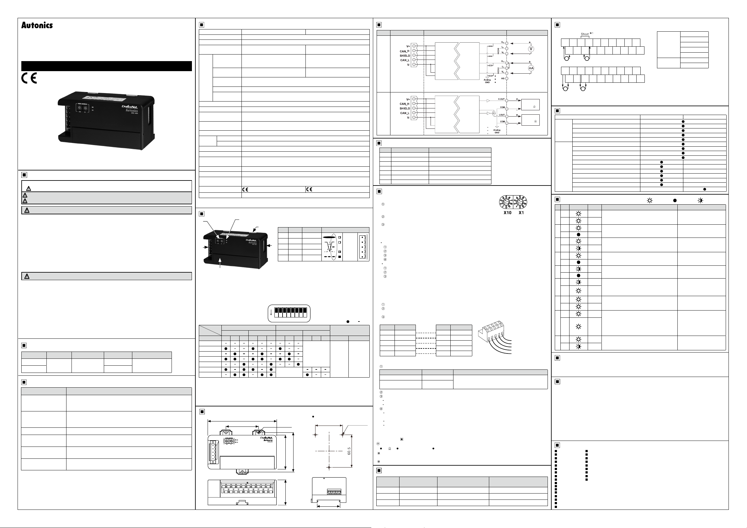
Connections
1. ARD-A 04
V
I0V1I1V2I2V3I
0
l~JI
V
0-
I I
V
2. ARD-AO04
V0V1I0I
I I
COM COM COM COM
B I I I I I I I I I
V
When wiring the communication connector, use cable and tap which meet the DeviceNet standard
※
and tighten the connector screw with a tightening torque of 0.5N.m.
When wiring the input/output terminal, tighten the connector screw with a tightening torque of 0 5N m.
※
1
Short
*
1111
V
AG AG AG AG
1g
V
1-
~
I I I I I I I
mA
N.C N.C N.C N.C N.C N.C
1
I I I I I I
mA
3
V
2-
3-
N.C N.C
N.C N.C
0-5VDC
1-5VDC
Voltage
Current
※1:
N.CN.CN.CN.CN.CN.C
-5-5VDC
0-10VDC
-10-10VDC
DC0-20mA
DC4-20mA
For current input, short between
+
V□
and I□+.
Functions
Model ARD-A 04(Input) ARD-AO04(Output)
Communication speed auto-detection
Network power voltage
Power on total time
Basic
Unit comment
Last maintenance date stored
Scaling
/O comment
Adjustment gradient
Adjustment offset
Number of AD Conversion Points Setting
Analog
Moving Average Filter of Number
Peak/Bottom hold
Disconnected cable detection
Comparator
Hysteresis
Fault state
Status LED
~
No Type LED status Color Description Troubleshooting
MS
1
2
3
4
5
6
7
8
9
~
For the detail information and instructions, please refer to user manual, and be sure to follow cautions
written in the technical descriptions (catalog, homepage).
~
1. Follow instructions in 'Cautions during Use'. Otherwise, it may cause unexpected accidents.
2. 24VDC power supply should be insulated and limited voltage/current or Class 2, SELV power supply
3. Keep away from high voltage lines or power lines to prevent inductive noise.
4. This unit may be used in the following environments.
~
■ ■
■ ■
■ ■
■ ■
■ ■
■ ■
■ ■
■ ■
■ ■
■
■
■
■
■
■
■
■
-¢-
NS Green
-¢-
MS
-¢-
NS
•
MS
-¢-
NS Green
MS
-¢-
*
NS
•
MS
NS
*
•
MS
NS
-¢-
*
MS
-¢-
NS
-¢-
MS
-¢-
NS
-¢-
MS
-¢-
NS
*
Manual
Caution during Use
device.
In case installing power line and input signal line closely, use line filter or varistor at power line and
shielded wire at input signal line.
Do not use near the equipment which generates strong magnetic force or high frequency noise.
Indoors (in the environment condition rated in 'Specifications')
①
Altitude max. 2,000m
②
Pollution degree 2
③
Installation category II
④
Major Products
Photoelectric Sensors Temperature Controllers
Fiber Optic Sensors Temperature/Humidity Transducers
Door Sensors SSR/Power Controllers
Door Side Sensors Counters
Area Sensors Timers
Proximity Sensors Panel Meters
Pressure Sensors Tachometer/Pulse(Rate)Meters
Rotary Encoders Display Units
Connector/Sockets Sensor Controllers
Switching Mode Power Supplies
Control Switches/Lamps/Buzzers
I/O Terminal Blocks & Cables
Stepper Motors/Drivers/Motion Controllers
Graphic/Logic Panels
Field Network Devices
Laser Marking System(Fiber, Co₂, Nd:yag)
Laser Welding/Soldering System
Normal operation
Green
Output communication or message
communication is working.
Standby duplicated node address check
Green
The status of standby for receiving message of
-
duplicated node address check from master unit.
Standby normal operation
Green
The status of standby for establish connection
from master unit.
Red
Watchdog timer error
Watchdog timer error occurs at the slave unit.
-
Switch setting error
Red
The status that DIP switch or another switch
-
setting is invalid.
Changed node address during normal
Red
operation
The status that node address is changed while it
Green
is operating normally.
Green
Invalid node address
The status of setting node address wrongly.
Red
Red
Duplicated node address
There is duplicated node address in the network.
Bus-Off error
Red
The communication is stopped with Bus-Off.
Green
Input/Output Connection time out
Red
•
•
•
•
•
•
-
:LED ON :LED OFF :LED Flash
-¢-
•
•
•
•
•
•
•
•
•
-
-
-
-
-
-
•
•
*
-
-
-
Change the slave unit.
Change the switch with valid
value and re-supply the
power.
Change the initial node
address when suppling the
power.
Change valid node address
and re-supply the power.
Change node address not
duplicated. Power on the
slave unit again. Check
master unit, communication,
cable, terminating resistance
and noise of network.
Check the master setting and
the user program.
DRW171436AA
 Loading...