

Page 1

The Authority in Custom Motorized Lifts
INSTALLATION MANUAL
INVIS
-O-TRAK
MODEL
000-INH
# 3
# 3000-INV
WWW.AUTON.COM
29102 Hancock Pkwy | Valencia, California 91355
Phone: 661-257-9282 | Fax: 661-295-5638
E-mail: [email protected]
Page 2
Installation
Step 1: Horizontal
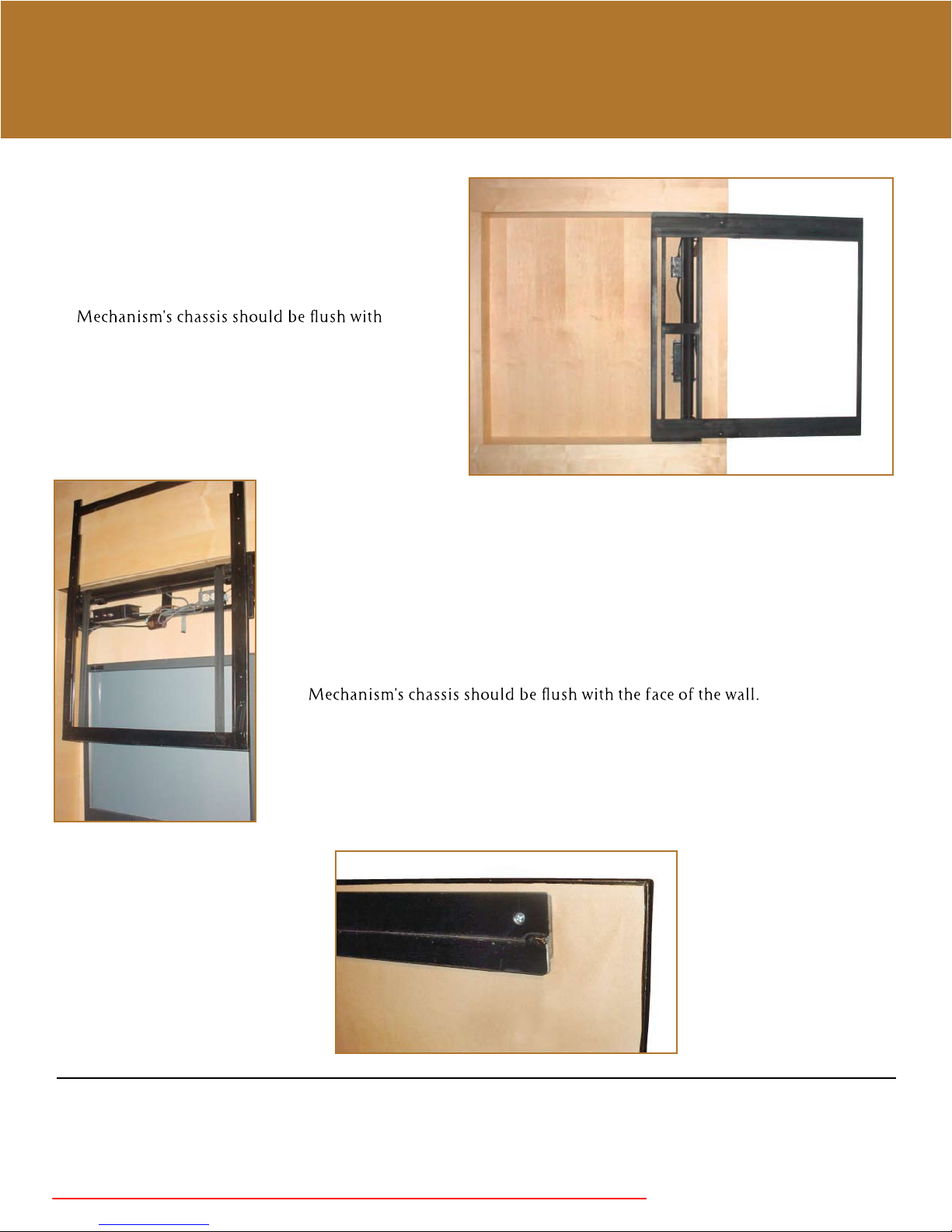
A. With mechanism in “open” position, attach
to jamb using all 8 mounting holes (4 upper
and 4 lower).
B.
the face of the wall.
C. Make certain horizontal rails are level, or
picture will not hang level.
Step 2:
A. Connect the Molex plugs
between the mechanism and
the control box.
B. Plug power cord into the 115
VAC outlet.
Step 1: Vertical
A. With mechanism in “open” position, attach to jamb using all 8 mounting holes
(4 right and 4 left).
B.
C. Make certain vertical rails areperpendicular, or picture will not hang level.
Step 3:
A. Attach “hanger rail”
to back side of painting.
Make certain it’s level.
Installation support:
We take great pride in manufacturing the best lift systems in the world. Our design and production techniques enable simple installation.
In the event that you require assistance, do not hesitate to contact one of our technicians. We will be happy to answer your questions and resolve
any problems you encounter during the installation process. Phone Support: 661-257-9282, ext. 104 • Email Support: [email protected]
Keep unit free of debris, keep covered prior to installation
Page 3
caution:
Dropping or jarring unit b
or other objects may cause misalignment of lif
ting walls, ceilings,
y hit
t.
Step 4: Adjust Motor & Limit Switches
(choose which motor you have either a ________ or a __________.
Limit switches are preset at the factory for optimal positioning and performance, but they may be changed.
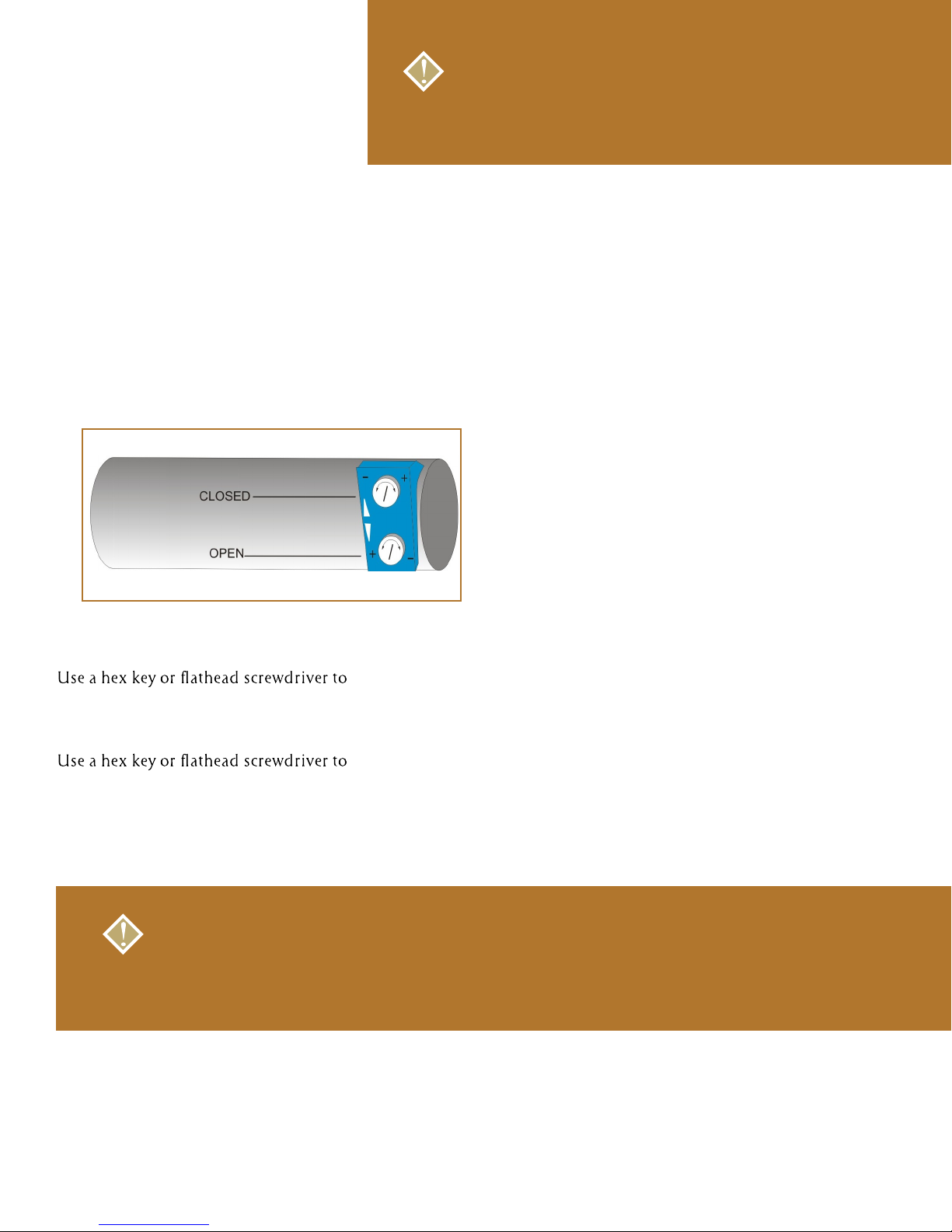
Two adjusting screws for the limit are located at the end of the motor. The bottom screw controls the open
travel , the top screw controls the closed travel.
Using a power tool to adjust the limits will void the warranty.
1. to increase open travel:
turn the top screw clockwise; turn counter-clockwise to decrease the
down travel.
2. to increase closed travel:
turn the bottom screw clockwise; turn counter-clockwise to decrease the
down travel.
3. Run the lift in the opposite direction for approximately 6” and stop. The motor will recognize the adjustment.
NOTE:
When adjusting the limit switches, turn the adjusting screw in very small increments so
over-adjustment doesn’t occur. Each full turn of the screw corresponds to 3/8” in travel.
*The motor is equipped with a built-in thermal overload protection system. In the event the lift (motor) is moved
too frequently in a short period of time, the unit will be disabled to prevent overheating and possible damage.
The unit will automatically re-set itself within 10-15 minutes.
Page 4
caution:
Dropping or jarring unit b
or other objects may cause misalignment of lif
ting walls, ceilings,
y hit
t.
Continued
Adjust Motor and Limit Switch Continued
Limit switches are preset at the factory for optimal positioning and performance, but they may be changed.
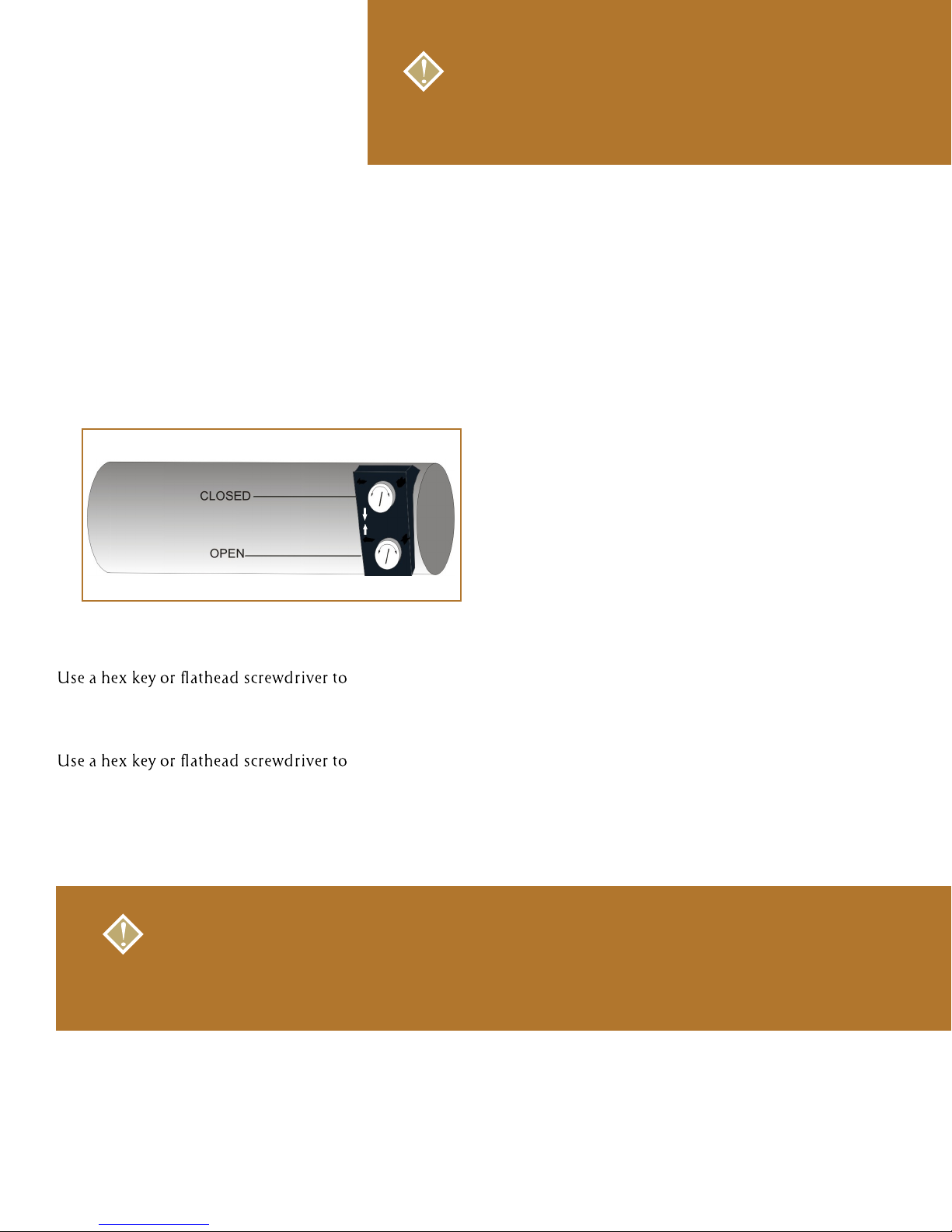
Two adjusting screws for the limit are located at the end of the motor. The bottom screw controls the open
travel, the top screw controls the closed travel.
-
+
-
+
Using a power tool to adjust the limits will void the warranty.
1. to increase open travel:
turn the bottom screw counter clockwise; turn clockwise to decrease the
up travel.
2. to increase closed travel:
turn the top screw counter clockwise; turn clockwise to decrease the
down travel.
3. Run the lift in the opposite direction for approximately 6” and stop. The motor will recognize the adjustment.
NOTE:
When adjusting the limit switches, turn the adjusting screw in very small increments so
over-adjustment doesn’t occur. Each full turn of the screw corresponds to 3/8” in travel.
*The motor is equipped with a built-in thermal overload protection system. In the event the lift (motor) is moved
too frequently in a short period of time, the unit will be disabled to prevent overheating and possible damage.
The unit will automatically re-set itself within 10-15 minutes.
Page 5
caution:
Dropping or jarring unit b
or other objects may cause misalignment of lif
ting walls, ceilings,
y hit
t.
Continued
Adjust Motor and Limit Switch Continued
Limit switches are preset at the factory for optimal positioning and performance, but they may be changed.
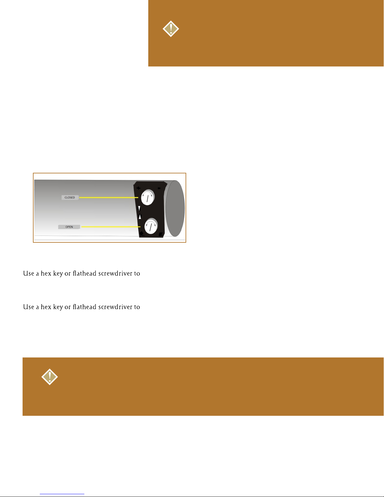
Two adjusting screws for the limit are located at the end of the motor. The top screw controls the open
travel , the bottom screw controls the closed travel.
- +
- +
Using a power tool to adjust the limits will void the warranty.
1. to increase open travel:
turn the top screw clockwise; turn counter-clockwise to decrease the
down travel.
2. to increase closed travel:
turn the bottom screw clockwise; turn counter-clockwise to decrease the
down travel.
3. Run the lift in the opposite direction for approximately 6” and stop. The motor will recognize the adjustment.
NOTE:
When adjusting the limit switches, turn the adjusting screw in very small increments so
over-adjustment doesn’t occur. Each full turn of the screw corresponds to 3/8” in travel.
*The motor is equipped with a built-in thermal overload protection system. In the event the lift (motor) is moved
too frequently in a short period of time, the unit will be disabled to prevent overheating and possible damage.
The unit will automatically re-set itself within 10-15 minutes.
Page 6
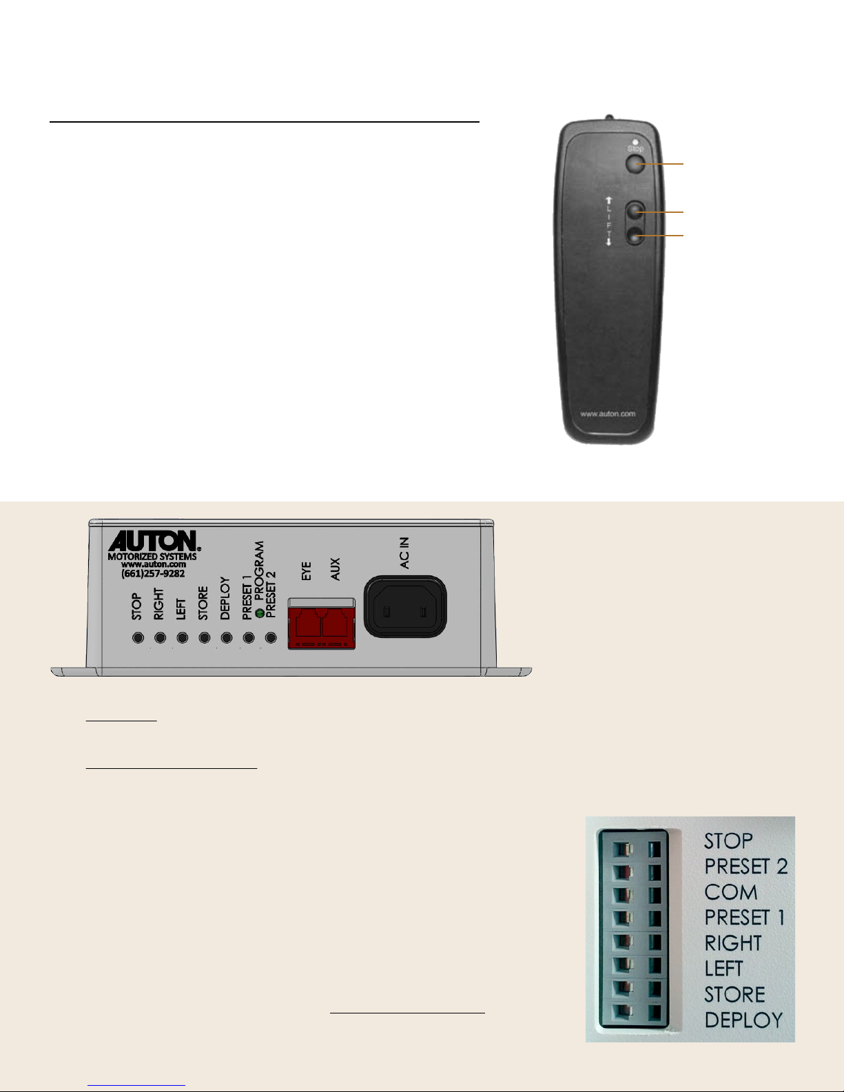
Step 5: Operation Instructions
Multi-Function Controller
The multi-function controller operates with RF (Radio Frequency),
IR (Infrared) simultaneously and has3 buttons:
1) Stop - Press and release for stop motion
2) Down/Right – Press and release for down (or Right) motion*
3) Up/Left – Press and release for up (or Left) motion*
Additional Button Functions:
A) When in motion, press the opposite direction.
The lift will pause for 1 second and then reverse direction.
B) When in motion, press the same button direction.
The lift will stop.
* Horizontal Installation moves left and right, Vertical Installation moves up and down
1) Stop
Up*
2)
Down
3)
*
IR Control
Connect the IR eye to the EYE port
Optional Control Method
Connect optional control accessory
to AUX port
Dry Contact Operation:
Short desired operation with COM
 Loading...