

SRR5-C / BSM User Manual
C ADAS D PD
Filename: SRR5-B Exhibit 2 - User Manual_156FE42.doc
Issue Status: 1.0 Document maturity: Released
Department: C ADAS D PD
page
1/8
Copyright by Continental 2016
All rights reserved
User Manual for
77 GHz Adaptive Radar Sensor
SRR5-C
AUTHORS
Name
Organisation
Section
Daniel Nenninger
Continental, C ADAS D PD
Systems Engineering
SRR5-C / BSM User Manual
C ADAS D PD
Filename: SRR5-B Exhibit 2 - User Manual_156FE42.doc
Issue Status: 1.0 Document maturity: Released
Department: C ADAS D PD
page
2/8
Copyright by Continental 2016
All rights reserved
Issue
status
(Index)
Document
maturity
(draft / valid)
Date of Issue
(200x-MM-DD)
Document Owner
Department
Description
0.1
Draft
2016-10-06
Dr. Frank Gruson
C ADAS D PD
0.2
Valid
2018-03-07
Daniel Nenninger
C ADAS D PD
Systems Engineer

SRR5-C / BSM User Manual
C ADAS D PD
Filename: SRR5-B Exhibit 2 - User Manual_156FE42.doc
Issue Status: 1.0 Document maturity: Released
Department: C ADAS D PD
page
3/8
Copyright by Continental 2016
All rights reserved
1. Table of Contents
1. TABLE OF CONTENTS...................................................................................................................................3
2. PURPOSE........................................................................................................................................................4
3. GENERAL INFORMATION..............................................................................................................................5
4. SRR5-C SENSOR COMPONENT DESCRIPTION..........................................................................................7
5. SRR5-C SENSOR SOFTWARE OPERATION................................................................................................8
LIST OF FIGURES
FIGURE 1: SENSOR SRR5-C......................................................................................................................................5
FIGURE 2: ILLUSTRATION OF THE MOUNTING POSITION OF THE SRR5-C.......................................................................5
FIGURE 3: FIELD OF VIEW OF THE SRR5-C ................................................................................................................6
FIGURE 4: EXPLODED VIEW OF THE SRR5-C..............................................................................................................7
SRR5-C / BSM User Manual
C ADAS D PD
Filename: SRR5-B Exhibit 2 - User Manual_156FE42.doc
Issue Status: 1.0 Document maturity: Released
Department: C ADAS D PD
page
4/8
Copyright by Continental 2016
All rights reserved
2. Purpose
In this document an operational description of Continental´s 77 GHz Advanced Radar Sensor SRR5-C is given.
Sufficient information is provided to understand the operation principle, the set up and the tuning of the radar
sensor.

SRR5-C / BSM User Manual
C ADAS D PD
Filename: SRR5-B Exhibit 2 - User Manual_156FE42.doc
Issue Status: 1.0 Document maturity: Released
Department: C ADAS D PD
page
5/8
Copyright by Continental 2016
All rights reserved
3. General information
The SRR5-C sensor measures independently the distance and velocity (Doppler's principle) to objects without
reflector in one measuring cycle on the basis of FMCW (Frequency Modulated Continuous Wave) with very fast
ramps. A special feature of the device is the simultaneous measurement of large distances up to 99 meters,
relative velocities between ±300 km/h and the angle relation between two objects.
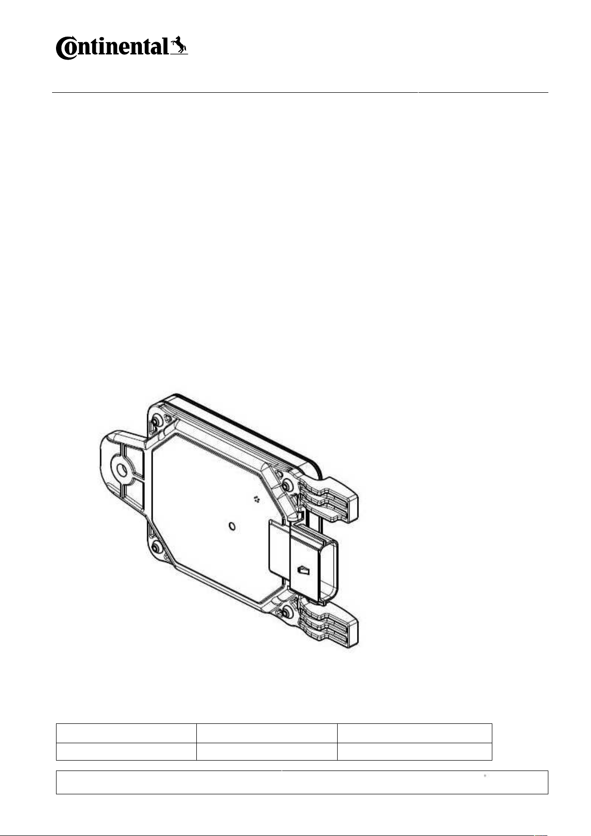
Figure 1 shows an image of the sensor SRR5-C.
Figure 1: Sensor SRR5-C
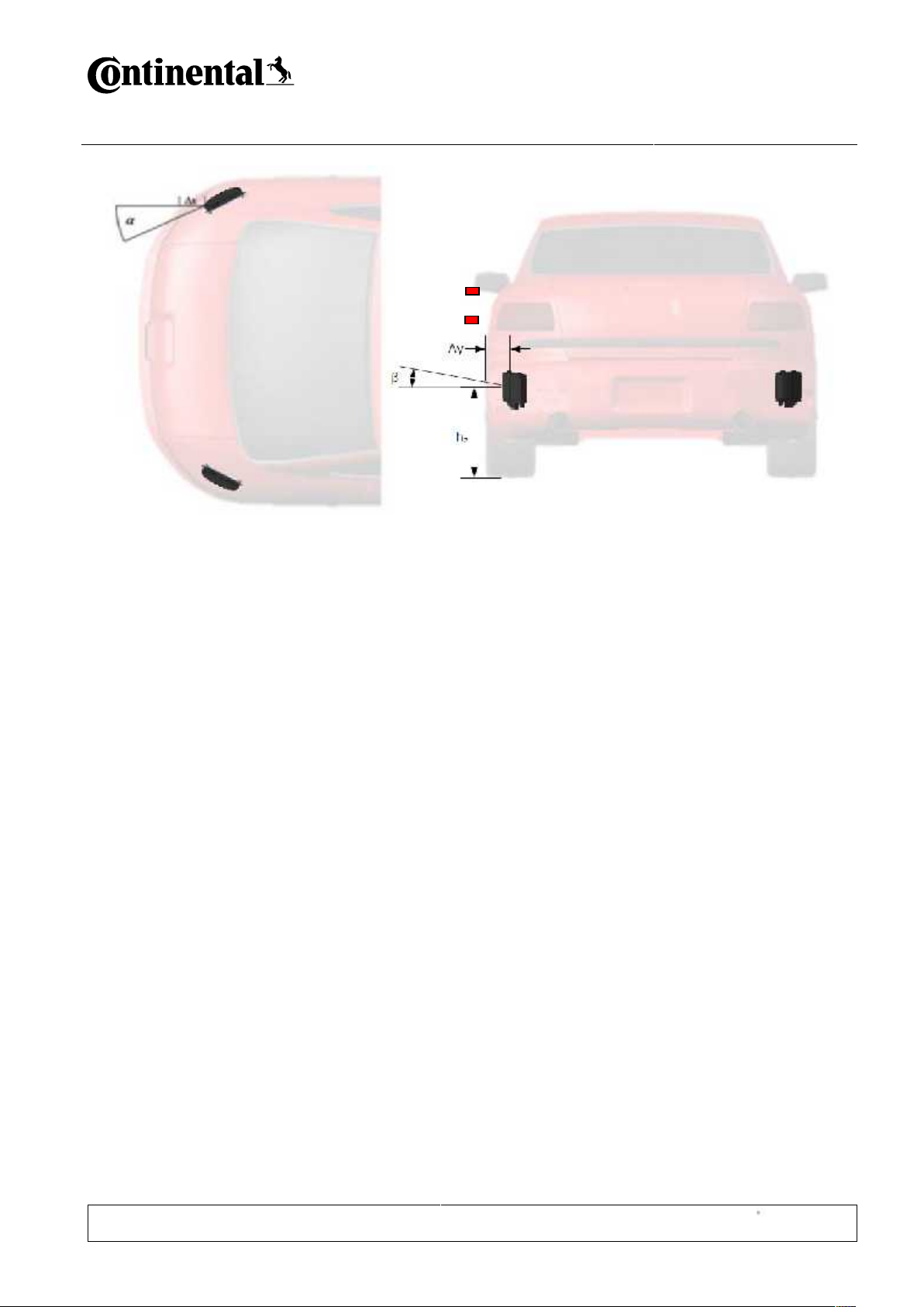
The sensor is mounted in the front or rear corner of the car behind the bumper, as illustrated in Figure 2.
SRR5-C / BSM User Manual
C ADAS D PD
Filename: SRR5-B Exhibit 2 - User Manual_156FE42.doc
Issue Status: 1.0 Document maturity: Released
Department: C ADAS D PD
page
6/8
Copyright by Continental 2016
All rights reserved
Figure 2: Illustration of the mounting position of the SRR5-C
The sensor performs in alternation a Short Range (SR) Scan cycle and a Far Range (FR) Scan cycle. The Short
Range Scan covers distances up to 12.6 meters and angles of ±90 degrees in front of the sensor. The Far
Range Scan covers distances up to 99 meters with angles of ±90 degrees.
Figure 3 illustrates the Field of View of the sensor SRR5-C for the Short Range Scan and the Far Range Scan
for different object classes and radar cross sections.

SRR5-C / BSM User Manual
C ADAS D PD
Filename: SRR5-B Exhibit 2 - User Manual_156FE42.doc
Issue Status: 1.0 Document maturity: Released
Department: C ADAS D PD
page
7/8
Copyright by Continental 2016
All rights reserved
Figure 3: Field of View of the SRR5-C
The sensor allows a detection of up to 64 objects in the given Field of View (FoV) and evaluates the current
constellation under consideration of all detected objects and among others the following information:
Vehicle Dynamics Data (e.g. Velocity, Acceleration, Yaw Rate of the host vehicle) which is transmitted to
the sensor from the car via the vehicle bus
The sensor SSR5-B is designed for comfort/safety applications in passenger cars and trucks like Blind Spot
Detection, Rear Cross Traffic Alert (with braking), Lane Change Assist, Trailer Detection
In dependence of the overall information the sensor outputs specific messages, which may then be used by
other vehicle components (braking system, power train, door modules etc.).

SRR5-C / BSM User Manual
C ADAS D PD
Filename: SRR5-B Exhibit 2 - User Manual_156FE42.doc
Issue Status: 1.0 Document maturity: Released
Department: C ADAS D PD
page
8/8
Copyright by Continental 2016
All rights reserved
4. SRR5-C Sensor Component Description
The SRR5-C sensor consists of the following components:
Plastic housing with sensor Controller Area Network (CAN) connector
Radio Frequency (RF) Printed Wiring Board (PCB) including the antenna which is plugged into the
housing
A PCB Carrier, which holds the antenna in place, and also provides a shield between the high
frequency and low frequency hardware.
Low Frequency (LF) PWB incl. Board-to-Board (B2B) Connector (connector between RF and LF unit)
A plastic molded radome through which the radar beams are emitted.
Figure 4: Exploded view of the SRR5-C

SRR5-C / BSM User Manual
C ADAS D PD
Filename: SRR5-B Exhibit 2 - User Manual_156FE42.doc
Issue Status: 1.0 Document maturity: Released
Department: C ADAS D PD
page
9/9
Copyright by Continental 2016
All rights reserved
5. SRR5-C Sensor Software Operation
Only one operational mode exists where the sensor measures continuously with pulse frequency modulation
(FM). The sensor operates in this mode over its life time in the vehicle, being powered by the vehicle power
supply.
Sensors which are dedicated for type approval contain a configured sensor SW which enters the operational
mode if a 12V power supply is applied to power supply pin and 0V is applied to GND pin. For USA type approval
using this special configured sensor software, a CW (continuous wave) mode is available.
No CAN bus messages, protocol or handshake protocol is necessary in this special mode.
 Loading...