

Page 1
1
2V BATTERY
INSTALLATION INSTRUCTIONS
2 1/16" ELECTRIC PYROMETER
GAUGES
2650-1131
Important
Pyrometers are sensitive, high accuracy instruments. They must be handled and installed with care to insure
proper performance. Carefully read and follow these instructions, and your pyrometer will provide you with a
long and accurate life.
OPTIONAL
SLIT TUBING
RECOMMENDED
(AVAILABLE AT MOST
HARDWARE STORES)
FIREWALL
GROMMET
BLACKWHITE
+12v
DASH
FUSE
(SEE CAUTION
BELOW)
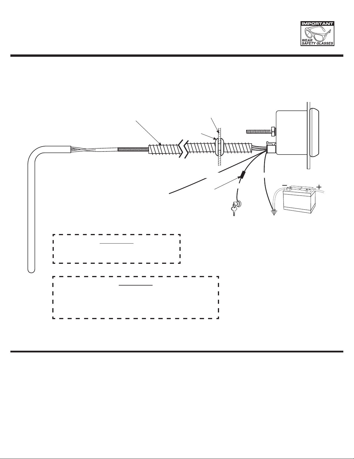
CAUTION:
Wear Safty glasses and disconnect the battery
before making any electrical connections.
CAUTION:
As a safety precaution, the +12V terminal of this product
should be fused before connecting to the 12V ignition switch.
We recommend using a 1 Amp, 3AG fast-acting type cartridge
fuse (Littlefuse
NOTE: When the ignition is off the pointer may not always rest at zero.
®
# 312 001 or an equivalent).
RED
+ 12v CONNECTION
GOOD ENGINE
GROUND
INSTALLATION
1. Check that you have all parts required for installation, and the engine is cool.
2. Disconnect the negative (-) battery cable.
3. Gauge mounts in a 2 1/16” hole. Use supplied brackets and nuts to secure gauge to dash.
4. Drill 1” diameter hole where wires pass through sheet metal (such as firewall) and install rubber grommet provided.
(Grommet will require slit.)
5. Connect the white wire to dash lighting or switchable 12v light source.
Page 2
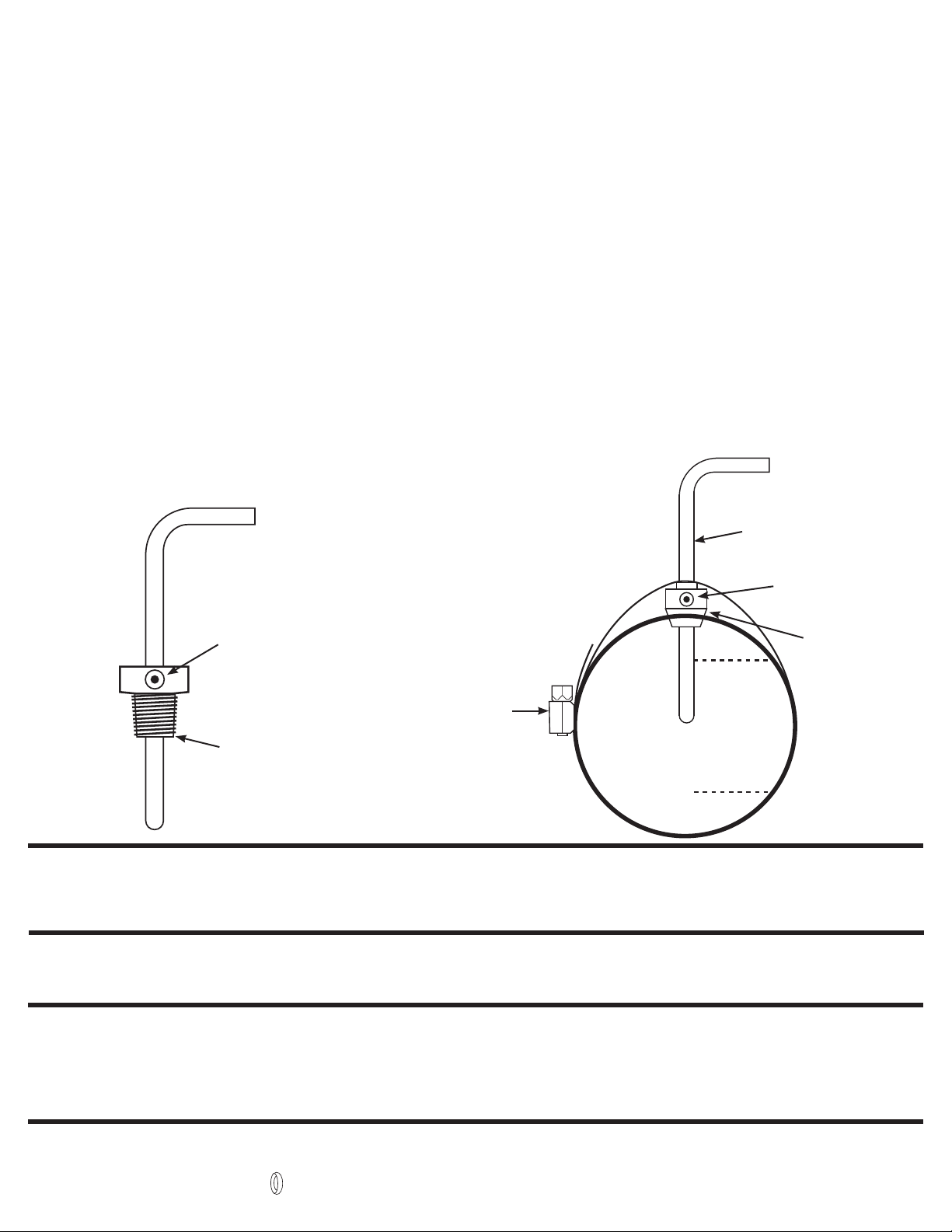
PROBE INSTALLATION
1. Begin by installing the thermocouple in the exhaust, then work back to the gauge. Installing the probe in the proper location will
insure optimal temperature readings. For non-turbo engines, install the probe 1-2 inches from the cylinder head.
For turbo engines, remove the exhaust manifold and install the probe 1-2 inches from the cylinder head. If the exhaust manifold
cannotberemoved,installtheprobe1-2inchesaftertheturboexhaustoutlet(Exhaustgastempscoulddropover200˚when
installing after the turbo). CLEAN ALL METAL FILINGS out of the exhaust manifold. Metal filings will damage the turbo impellor
if they go through the turbo.
The probe can be mounted in two different ways, so please use the method best suited for your needs.
A) Pre-existing 1/8” NPT Threaded Hole: Simply screw the threaded fitting into the hole, insert the probe, and tighten the set
screw snugly onto the probe. (Caution: do not over tighten set screw or damage to probe may occur.) Make sure the probe is
oriented so the wires do not come in contact with, or become too close to the manifold or other hot engine parts.
See illustration for details.
B) Stainless Clamp Method: This method is for applications that require frequent removal of the manifold or header for service,
or just faster and easier installation. Drill a 7/16” diameter hole about 6” down from the junction of the exhaust pipe to manifold
junction. Undo the clamp and slide the probe into the hole in the clamp. Slide the set screw collar onto the probe.
Before tightening the collar in position make sure that when inserted, the probe will have it’s tip in the middle two-thirds of the
exhaust stream. Tighten screw collar in position. (Caution: do not over tighten set screw or damage to probe may occur.)
Hold the clamp open when inserting the probe into the 13/32” hole. Re-join the clamp ends and tighten in position.
Make sure the probe is oriented so the wires do not come in contact with, or become too close to the manifold or other hot
engine parts. See the illustration below for details.
2. With the probe installed, the wire harness can now be routed to the gauge. The wire harness is an integral part of the pyrometer
calibration. It may not be shortened or lengthened without affecting the gauge calibration. You will need to determine a suitable
location to coil the excess wire, and tie it loosely with a wire tie. (Loosely tying the excess coil prevents embritlement caused by
vibration.) Pass the harness through the fire wall using an existing hole, or drill a 1” diameter hole and use the rubber grommet
provided to protect the wire from damage.
A. Pre-existing 1/8” NPT Threaded Hole B. Stainless Clamp Method
PROBE
SET SCREW
SET SCREW
1/8” NPT FITTING
STAINLESS
CLAMP
middle 2/3
COLLAR
Power-Up
The pointer will move backward to the stop pin and then display actual temperature. This procedure is an auto-calibration function and is
performed on every power-up. While this test is being performed, the gauge may make a clicking sound. This is normal.
For service send your product to Auto Meter in a well packed shipping carton. Please include a note explaining what the problem is along with your phone number. Please specify when you need
the product back. If you need it back immediately mark the outside of the box “RUSH REPAIR,” and Auto Meter will service product within two days after receiving it. ($10.00 charge will be added
to the cost of “RUSH REPAIR.”) If you are sending product back for Warranty adjustment, you must include a copy (or original) of your sales receipt from the place of purchase.
SERVICE
12 MONTH LIMITED WARRANTY
Auto Meter Products, Inc. warrants to the consumer that all Auto Meter High Performance products will be free from defects in material and workmanship for a period of twelve (12) months from date of the
original purchase. Products that fail within this 12 month warranty period will be repaired or replaced at Auto Meter’s option to the consumer, when it is determined by Auto Meter Products, Inc. that the product
failed due to defects in material or workmanship. This warranty is limited to the repair or replacement of parts in the Auto Meter instruments. In no event shall this warranty exceed the original purchase price of
the Auto Meter instruments nor shall Auto Meter Products, Inc. be responsible for special, incidental or consequential damages or costs incurred due to the failure of this product. Warranty claims to Auto Meter
must be transportation prepaid and accompanied with dated proof of purchase. This warranty applies only to the original purchaser of product and is non-transferable. All implied warranties shall be limited in
duration to the said 12 month warranty period. Breaking the instrument seal, improper use or installation, accident, water damage, abuse, unauthorized repairs or alterations voids this warranty. Auto Meter
Products, Inc. disclaims any liability for consequential damages due to breach of any written or implied warranty on all products manufactured by Auto Meter.
FOR SERVICE SEND TO: AUTO METER PRODUCTS, INC. 413 W. Elm St., Sycamore, IL 60178 USA (815) 899-0801
Email us at service@autometer.com
http://www.autometer.com
© 2006 Auto Meter Products, Inc.
The Super Bezel is a registered trademark of Auto Meter Products, Inc.
2650-1131 2/23/06
 Loading...