

Page 1
2650-859F
COIL
12V BATTERY
9
8
7
6
5
4
3
2
0
1
M
A
D
E
I
N
U
S
A
C
O
P
Y
R
I
G
H
T
P
A
T
E
N
T
P
E
N
D
I
N
G
A
U
T
O
M
E
T
E
R
P
R
O
D
U
C
T
S
,
I
N
C
.
S
Y
C
A
M
O
R
E
,
I
L
U
S
A
R
P
M
X1000
•
CANCEL
MENU
SELECT
•
ENTER
INSTALLATION INSTRUCTIONS
5” PRO-COMP PRO-STOCK TACH
If after completely reading these instructions you have questions regarding the operation or installation of your instrument(s),
please contact Auto Meter Technical Service at 815-899-0801.
You may also email us at service@autometer.com.
Additional information can also be found at http://www.autometer.com/tech_faq.aspx
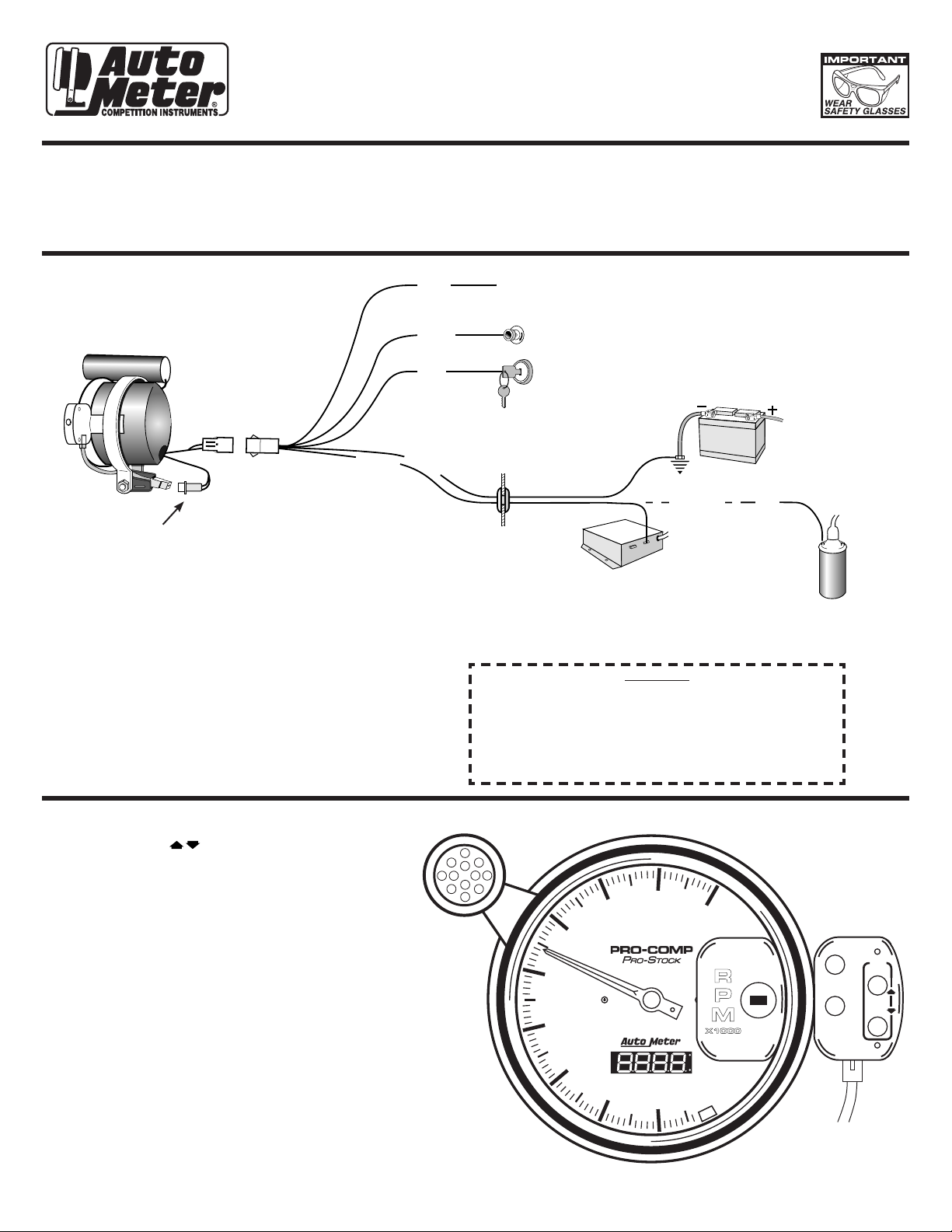
Wiring
P1
P3
P2
Shift-Lite connector must be plugged
in prior to operation. It has been left
disconnected for shipping purposes.
NOTE: This tachometer operates on standard, factory
electronic and high performance electronic
racing ignitions, such as Crane and MSD. (This
tach is NOT recommended for use on Accel’s
BEI or Laser I & II ignitions. These ignitions
require model 5215 adapter.)
NOTE: With power off the tach pointer may not always
rest at zero. This is a natural characteristic of the
High Performance air-core meter movement used
in this tachometer. When the engine is started,
the pointer will position on the correct RPM.
Green
QUESTIONS:
Blue
White
Red
Black
Grommet in
Firewall
Warranty will be void if connected to coil when using
an aftermarket ignition box such as, but not limited to
products from the following manufacturers: MSD, Crane,
Jacobs, Mallory, Holley, Etc.. Prior to installation of your
tachometer, check with the ignition box manufacturer for
recommended tachometer signal location.
Clutch Switch or
+12V Line Lock Switch
12V Dash Lighting
12V Ignition Switch (+)
*Electronic Ignition (Such
as GM, HEI or MSD):
connect to tach terminal.
NOTE: The Blue wire is used to start
the setpoint change delay and
the sequence of four shift points.
(Momentary 12 volts will activate
the delay and shift sequence.)
Good Engine Ground
Green
OR
Standard ignition:
GREEN wire
attaches to coil
negative (-).
WARNING
Introduction To Tach Set-Up
1. The Pro-Stock Tach uses a menu system for configuration.
Use the arrows ( ) to scroll up and down the menu.
When you reach the bottom or top of the menu you will
automatically jump to the other end of the menu.
2. To select a menu option press the ENTER button. If at
any time you want to exit the menu you are currently
in, press the CANCEL button. This will take you back to
the TACH display and will not store the entries you have
made.
3. Press the ENTER key to store the settings you have
entered. After pressing ENTER, the only way to return
to the original settings is to return to step 1 and reset as
needed.
NOTE: The included 12 LED Shift-Lite has 3 intensity
settings. The switch in the back of the Shift-Lite will
select the intensity of the Shift-Lite. The intensities
are as follows;
HI - Very Bright - For use on a bright sunny day
MED - Bright - For use on a cloudy or over cast day
LOW - Dim - For use at night
Page 2
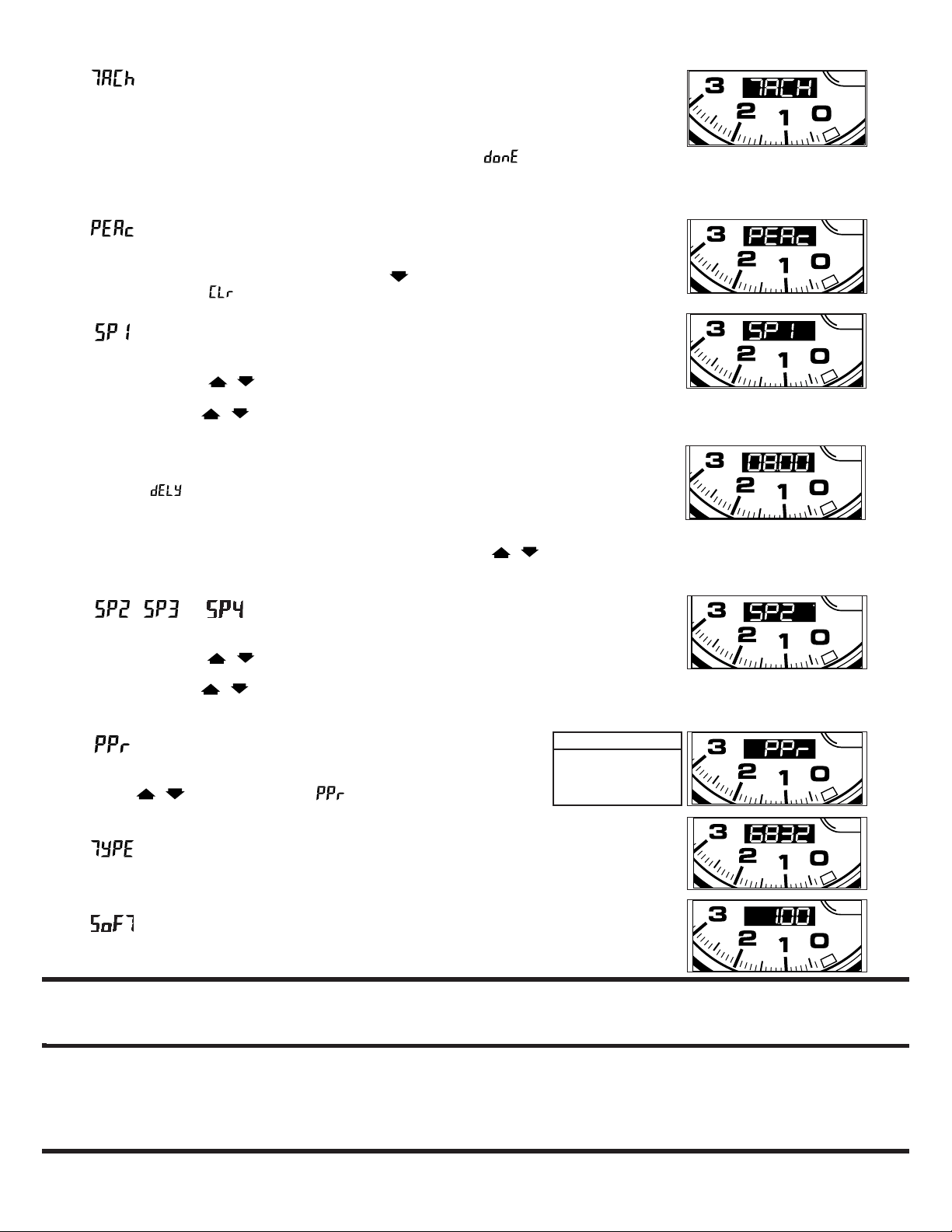
Main Menu Options
A. - Tach Mode
In Tach Mode, the Tach operates as a standard tach. It displays RPM and operates the shift light.
All 4 shift points are active only when the blue wire is used. When the blue wire is not used, only
the first shift point is active. When the tach RPM is less than 3,000 RPM the tach will return to
shiftpoint 1, and hold shiftpoint 1, and the delay timer will be reset. Timer will not start again until
blue wire is activated. The shift-lite will not light after the fourth shift and will be displayed.
The shift-lite will not operate when the blue wire is connected to a +12V source or when the hold
setpoint delay is running. Momentary 12 volts will activate the delay and shift sequence.
B. - Peak Recall
1. Press ENTER, the current peak RPM value will be displayed and a LED on the right side of
the display will light up.
2. Press ENTER to return to the MAIN Menu or; press to clear the Peak Recall value. The
display will change to . Press ENTER and the peak will be cleared.
C. - Set Shift Setpoint #1
1. Press ENTER, the current setpoint will be displayed on LED.
2. Adjust Shift Setpoint 1 as follows;
a. Press and hold the / arrow.
• The displayed RPM will change.
• Continue holding / and the RPM display will increase in speed.
NOTE: The RPM value increases in 13 RPM increments. The display shows the RPM
value in decimal form (RPM x 1000). The decimal point represents a comma (Example:
07.99=7,990).
b. When the desired reading is displayed, press ENTER.
c. The word will now be displayed, press ENTER to continue.
d. The Hold Setpoint 1 Delay is now displayed. The tach reads a profile of RPM increase and
decrease as a shiftpoint. The delay feature prevents inadvertently triggering a shiftpoint due
to wheel spin or inconsistent throttle off the launch.
e. Set the delay time slightly before your known first shiftpoint with the / arrows.
3. Press ENTER to store the setpoint and return to the Main Menu.
The display shows 8,000 RPM
D. , & - Set Shift Setpoint #2, 3 & 4
1. Press ENTER, the current setpoint will be displayed.
2. Adjust the Shift Setpoints as follows;
a. Press and hold the / arrow.
• The display RPM will change one count.
• Continue holding / and the RPM display will increase in speed.
3. When the desired reading is displayed, press ENTER and return to the Main Menu.
E. - Pulse Per Revolution
Sets the Pulse Per Revolution Setting.
1. Press ENTER to display the current pulse per revolution setting.
2. Press the / arrows to change the .
3. Press ENTER to store the setpoint and return to the Main Menu.
PPR Table
2PPR = 4 Cy 4 STR
3PPR = 6 Cy 4 STR
4PPR = 8 Cy 4 STR
F. - Displays the Tachs Model Number
1. Press ENTER to display the model number.
2. Press ENTER to return to the Main Menu.
G. - Displays Current Software Revision
1. Press ENTER to display the current software version number.
2. Press ENTER to return to the Main Menu.
For service send your product to Auto Meter in a well packed shipping carton. Please include a note explaining what the problem is along with your phone number. Please specify when you
need the product back. If you need it back immediately mark the outside of the box “RUSH REPAIR,” and Auto Meter will service product within two days after receiving it. ($10.00 charge will be
added to the cost of “RUSH REPAIR.”) If you are sending product back for Warranty adjustment, you must include a copy (or original) of your sales receipt from the place of purchase.
12 MONTH LIMITED WARRANTY
Auto Meter Products, Inc. warrants to the consumer that all Auto Meter High Performance products will be free from defects in material and workmanship for a period of twelve (12) months from date of the
original purchase. Products that fail within this 12 month warranty period will be repaired or replaced at Auto Meter’s option to the consumer, when it is determined by Auto Meter Products, Inc. that the product
failed due to defects in material or workmanship. This warranty is limited to the repair or replacement of parts in the Auto Meter instruments. In no event shall this warranty exceed the original purchase price
of the Auto Meter instruments nor shall Auto Meter Products, Inc. be responsible for special, incidental or consequential damages or costs incurred due to the failure of this product. Warranty claims to Auto
Meter must be transportation prepaid and accompanied with dated proof of purchase. This warranty applies only to the original purchaser of product and is non-transferable. All implied warranties shall be
limited in duration to the said 12 month warranty period. Breaking the instrument seal, improper use or installation, accident, water damage, abuse, unauthorized repairs or alterations voids this warranty. Auto
Meter Products, Inc. disclaims any liability for consequential damages due to breach of any written or implied warranty on all products manufactured by Auto Meter.
FOR SERVICE SEND TO: AUTO METER PRODUCTS, INC. 413 W. Elm St., Sycamore, IL 60178 USA (815) 899-0801
© 2005 Auto Meter Products, Inc.
Email us at service@autometer.com
SERVICE
2650-859F 9/14/05
 Loading...