

Page 1
INSTALLATION INSTRUCTIONS
12v b
A
TTER
Y
DIGITAL bOOST/vAC GAUGE
2650-1236-00
If after completely reading these instructions you have questions regarding the operation or installation of your instrument(s),
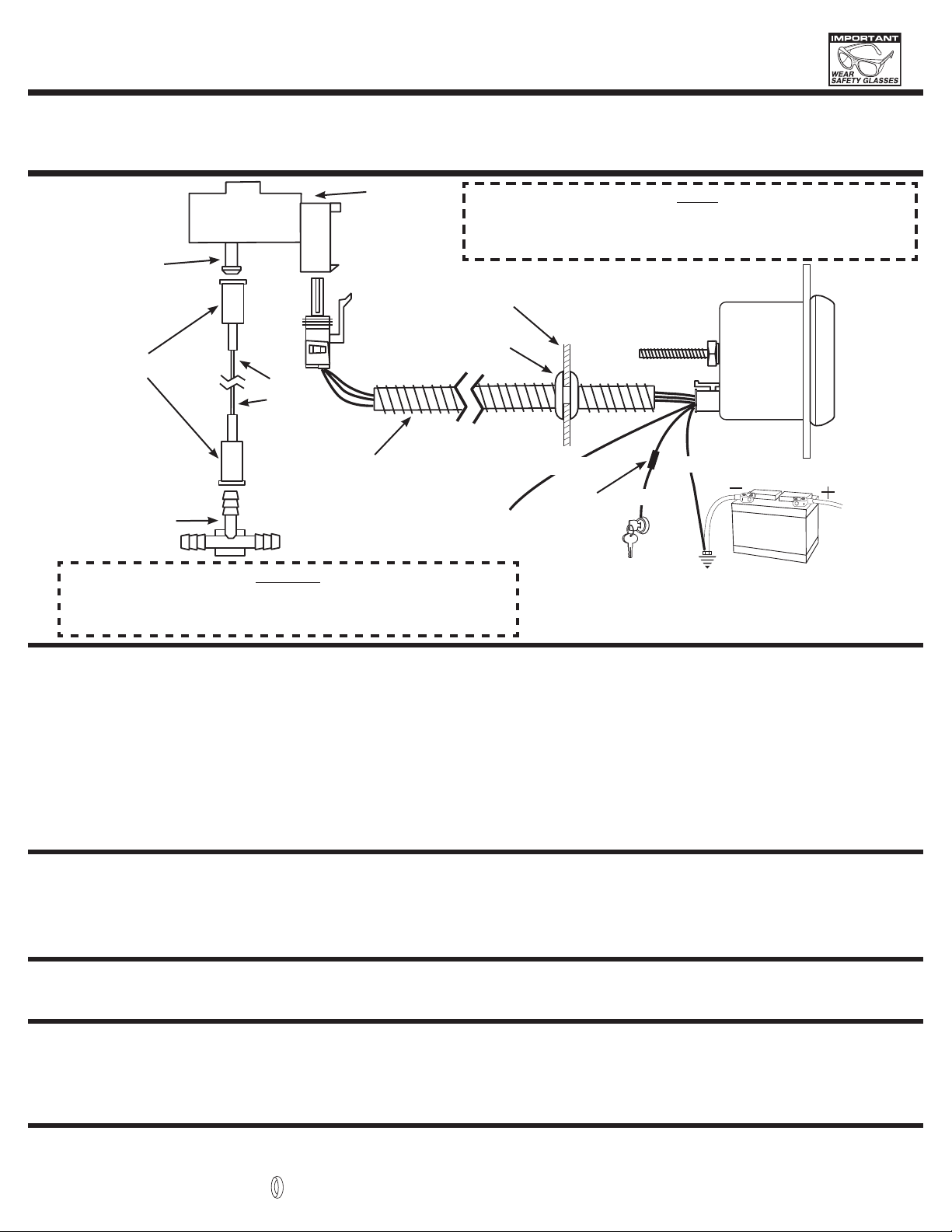
PRESSURE
PORT
TUBING ADAPTER
VACUUM “T”
3
/16 x 3/16 x ¼
please contact Auto Meter Technical Service at 815-899-0801.
You may also email us at service@autometer.com.
Additional information can also be found at http://www.autometer.com
MAP
SENSOR
MAP Sensor should be mounted with PRESSURE PORT facing down.
NOTE:
Failure to do so could result in inaccurate readings due to condensation
in the line. (Bracket fabrication may be required.)
FIREWALL
GROMMET
NYLON
TUBING
WHITEOPTIONAL
BLACK
SLIT TUBING
RECOMMENDED
(AVAILABLE AT MOST
HARDWARE STORES)
+12v DASH
LIGHTING
FUSE
(SEE
CAUTION
BELOW)
RED
QUESTIONS ?
As a safety precaution, the +12V terminal of this product should be fused before
CAUTION!
connecting to the 12V ignition switch. We recommend using a 1 Amp, 3AG fastacting type cartridge fuse (Littlefuse® # 312 001 or an equivalent).
+ 12v CONNECTION
*SEE STEP 8 BELOW
GOOD ENGINE
GROUND
Installation
1. Check that you have all parts required for installation, and the engine is cool.
2. Disconnect the negative (-) battery cable.
3. Gauge mounts in a 21⁄16” hole. Use supplied brackets and nuts to secure gauge to dash.
4. Drill 1” diameter hole where wires pass through sheet metal (such as firewall) and install rubber grommet provided . (Grommet will require slit.)
5. Securely mount the MAP sensor to the firewall or inner fender with pressure port facing down. (Bracket fabrication may be required.)
6. Install T-Fitting in a manifold vacuum hose. Attach one end of the nylon tubing to the T-Fitting using a tubing adapter. Connect the other end of the nylon tubing to the MAP
sensor with the other tubing adapter. If different size “T” is needed you may obtain one from most parts stores. Rubber boot requires ¼" leg of “T”.
7. Connect the white wire to dash lighting or switchable 12v light source. Digital display will dim when power is applied.
8. Connect the red power wire to a switched +12 volt source that maintains power during engine cranking. Most vehicles break the electrical connection to accessories while
the engine is being started. If the boost gauge is connected to one of these circuits, the auto zero function will not work properly and inaccurate readings will result.
To determine whether a switched source maintains power during starting, look for electrical accessories in the vehicle that remain on while the engine is being started.
Connect the red power wire to the same circuit that powers one of these accessories.
Power-Up
When power is applied to the gauge, the display will light up with all eights immediately followed by the gauge firmware version. After the firmware version is momentarily
displayed, the gauge will begin normal operation and display real time sender readings.
Electronic Boost/Vac gauges are equipped with an auto zero function used to compensate for operation at varying altitudes. This function takes a pressure reading during the
time that the key switch “flies through” from the ON position to the START position. The reading represents 0 pressure and is used to set the zero point on the gauge each time the
engine is started.
For service send your product to Auto Meter in a well packed shipping carton. Please include a note explaining what the problem is along with your phone number. Please specify when you
need the product back. If you need it back immediately mark the outside of the box “RUSH REPAIR,” and Auto Meter will service product within two days after receiving it. ($10.00 charge will be
added to the cost of “RUSH REPAIR.”) If you are sending product back for Warranty adjustment, you must include a copy (or original) of your sales receipt from the place of purchase.
Auto Meter Products, Inc. warrants to the consumer that all Auto Meter High Performance products will be free from defects in material and workmanship for a period of twelve (12) months from date of the
original purchase. Products that fail within this 12 month warranty period will be repaired or replaced at Auto Meter’s option to the consumer, when it is determined by Auto Meter Products, Inc. that the product
failed due to defects in material or workmanship. This warranty is limited to the repair or replacement of parts in the Auto Meter instruments. In no event shall this warranty exceed the original purchase price of
the Auto Meter instruments nor shall Auto Meter Products, Inc. be responsible for special, incidental or consequential damages or costs incurred due to the failure of this product. Warranty claims to Auto Meter
must be transportation prepaid and accompanied with dated proof of purchase. This warranty applies only to the original purchaser of product and is non-transferable. All implied warranties shall be limited in
duration to the said 12 month warranty period. Breaking the instrument seal, improper use or installation, accident, water damage, abuse, unauthorized repairs or alterations voids this warranty. Auto Meter
Products, Inc. disclaims any liability for consequential damages due to breach of any written or implied warranty on all products manufactured by Auto Meter.
12 MONTH LIMITED WARRANTY
SERvICE
FOR SERVICE SEND TO: AUTO METER PRODUCTS, INC. 413 W. Elm St., Sycamore, IL 60178 USA (815) 899-0801
Email us at service@autometer.com
http://www.autometer.com
© 2007 Auto Meter Products, Inc.
The Super Bezel is a registered trademark of Auto Meter Products, Inc.
2650-1236-00 5/17/07
 Loading...