

Page 1

Race Dash
Users Guide
Part No. 2650-1474-00
Page 2

Page 3
Preface
Preface
Congratulations
Congratulations on your purchase of the Race Dash Display from
Auto Meter.
This system will give you a wealth of information to enable you
to obtain the maximum safe performance from your vehicle.
Purpose of this manual
This manual will help you install and use your Auto Meter Race
Dash Display. It explains how to set up and configure the system
for your vehicle.
Units of Measure
Units used in the various display parameters are shown in the
following table.
Parameter Type Units
Speed MPH
Temperature ºF
Wheel Circumference Inches
Pressure PSI
Race Dash Users Guide i
Page 4

Preface
Related Products From Auto Meter
If you need information about other Auto Meter products, these
can be obtained from Auto Meter or from your local Auto Meter
dealer. Products available from Auto Meter include:
• Tachometers
• Playback Tachometers
• Speedometers
• Boost Gauges
• Analog Sensors
• Digital Sensors
• Data Logging Systems
• Display and Logging Systems
• Display and Analysis Software
Please visit www.autometer.com
for a complete listing.
Who to Contact at Auto Meter in Case of
Difficulty
Auto Meter and its approved distributors provide a
comprehensive Technical Help service to assist with your
inquiries. Contact Auto Meter toll free at 866-248-6357 for
technical support or email us at service@autometer.com.
You may also visit us on the web at www.autometer.com
accessories, instructions, view FAQ’s and for installation tech
tips.
Auto Meter ® is a registered trademark of Auto Meter Products Inc.
Information in this publication is subject to change without notice and does not represent
a commitment on the part of Auto Meter. No responsibility is accepted for error or
omission. Copyright © 2009 Auto Meter Products Inc
to view
ii Race Dash Users Guide
Page 5

Contents
Contents
Preface i
Related Products From Auto Meter ii
Who to Contact at Auto Meter in Case of Difficulty ii
Contents iii
Chapter 1. Introducing the Display System 1
How to Use this Manual 2
Chapter 2. Getting Started 3
The Display Module 4
Wiring Harness 4
Connecting the Components 5
Chapter 3. Operating the Display System 6
Switching the Display System On 6
Changing the Display Layers 6
Peak Values (Tell Tales) 9
Alarms 11
Lap Times 13
Gear Shift Light 14
Making a Recording 14
Playback Menu 15
Replaying the Recorded Data 16
Chapter 4. Configuring the Display System 17
System Configuration Mode 17
Leaving Configuration mode 20
Chapter 5. Installing the Display System 21
Who can install the Display System? 21
Tools Needed to Install the Display System 21
Preconfigured Display Systems 21
Fitting the Display Module 22
Switches 23
Warning Lights 24
Engine Speed (RPM) Measurement 24
Connecting the Display System to the Ignition System 25
Pressure Sensors 27
Temperature Sensors 28
VSS Pulse Amplifier Interface 29
Lap Timing Sensor (optional) 33
Trackside Infra-Red Lap Beacon (optional) 34
Wiring harness 35
Checks and Alarms 36
Race Dash Users Guide iii
Page 6

Contents
Chapter 6. Troubleshooting 37
Appendix A. Template for the Display Module 44
Appendix B. Wiring Harness Diagram 46
Appendix C. Summary of Switch Functions 47
Appendix D. Service and Support 48
Service 48
12 Month Limited Warranty 49
Index 50
iv Race Dash Users Guide
Page 7

Chapter1. Introducing the Display Systems
Chapter 1. Introducing the Display
System
The Auto Meter Race Dash Display System monitors and
displays a range of values, known as performance parameters,
needed for effective car and driver management in most
competitive situations.
The system combines an analog tachometer with a digital display
for the following performance parameters:
• Engine speed (RPM)
• Oil pressure
• Oil temperature
• Water Temperature
• Fuel Pressure
You can view the peak values (tell-tales) for all the parameters.
The system provides a range of warning messages based on
preset alarm values for the following performance parameters:
• Oil pressure
• Oil temperature
• Water temperature
You can enable or disable the warning system for each parameter
individually.
You can redefine the preset alarm value for each parameter to a
value that is more suitable for your vehicle.
The system provides a shift light that illuminates above a RPM
value that you define for your vehicle.
• Battery Voltage
• Wheel speed
• Lap times up to 45
minutes
• Fuel pressure
• Battery voltage
Race Dash Users Guide 1
Page 8
Chapter 1. Introducing the Display Systems
How to Use this Manual
Auto Meter recommends that you unpack and connect the
components in the system before you install it in your vehicle.
This will enable you to familiarize yourself with operating the
display and configuring it for the vehicle in which you intend to
install it.
This manual starts by taking you through the process of setting
up the system before installation, operating the digital display,
configuring the system, setting the alarm values and installing it
in the vehicle. By the end of Chapter 2, you will have set up the
system so that you will be assured that it is functioning normally.
You can then read Chapter 3 and practice using its functions.
Chapter 4 takes you through configuring it for your vehicle.
Chapter 5 explains how to install it in the vehicle and Chapter 6
provides a set of trouble-shooting guidelines.
A template for the Race Dash dashboard cut-out is provided in
Appendix A and a schematic diagram of the wiring harness is in
Appendix B.
Please note that this manual does not attempt to explain how to
interpret or use the information from the Race Dash as this is
very specific to the type of vehicle in which it is installed and the
type of competition in which the vehicle is engaged.
2 Race Dash Users Guide
Page 9

Chapter 2. Getting Started
Chapter 2. Getting Started
This chapter guides you through the initial unpacking and setting
up of the equipment for pre-installation checks and
familiarization with its operation.
Standard Race Dash Display System Items
The Race Dash Display System is supplied with the following
standard components
Quantity Description
1 Display Module with 2 mounting brackets
1 Wiring Harness
2 Pressure Sensors
2 Temperature Sensors
4 Switches (supplied with and to be connected to the wiring harness)
1 Pulse Amplifier for VSS input
Optional Race Dash Display System Items
The Race Dash Display System can be used with the following
optional components:
Quantity Description
1 Infra-red Lap Time Receiver (model # 5266)
1 Infra-red Lap Time Beacon (model # 5267)
1 External Shift Light (model # 9580)
Race Dash Users Guide 3
Page 10
Chapter 2. Getting Started
The Display Module
The Display Module consists of an analog tachometer and a
digital display panel.
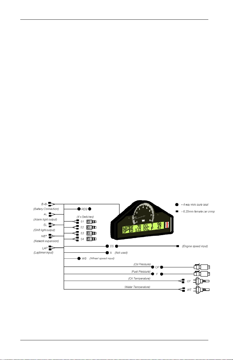
The Display Module is connected to a variety of sensors by a
wiring harness. The wiring harness has a 19-way military
connector for connection to the Display Module.
Wiring Harness
Each of the wires in the harness is labeled.
Labels on Short Cables Connection To
REG 5 volt regulator stub
S1 to S4 Switches 1 to 4
WS Wheel speed sensor
LAP Lap timing sensor
SL Shift light
AL Alarm warning light
4 Race Dash Users Guide
Page 11
Chapter 2. Getting Started
Labels on Long Cables Connection To
ES Engine speed (RPM)
OT Oil temperature sensor
WT Water temperature sensor
OP Oil pressure sensor
F Fuel pressure sensor
B + Battery Positive
B - Battery Negative (Ground)
Connecting the Components
1. Connect the wiring harness to the display module.
2. Connect the four switches to the cables labeled S1 to S4.
3. Connect each of the sensors that you have purchased to the
appropriate wire in the wiring harness, as shown above.
4. Connect a 12v DC power supply to the power input cable.
5. Switch on the 12v DC power supply.
The Display Module should start up with an alarm signal
indicating low oil pressure.
This is normal in this environment.
You can now proceed to familiarize yourself with operating the
Display Module.
Race Dash Users Guide 5
Page 12

Chapter 3. Operating the Display System
Chapter 3. Operating the Display System
This chapter takes you through the operation of the system so
that you can familiarize yourself with its use before you install it
in the vehicle.
Switching the Display System On
You will have switched the system on already if you have
followed the instructions in the previous chapter and have just
set the system up for the first time before installing it.
When installed in the vehicle, the system is switched on when
you switch the ignition on.
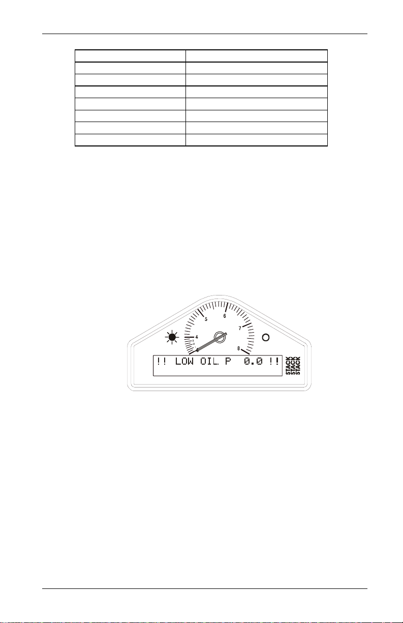
When the power is first switched on, the digital display will
immediately show a "Low Oil P" warning and the alarm light
will come on. The tachometer will reset itself by moving the
needle until it touches the stop-pin and then moving it back to
the zero RPM position. Press Switch 2 or Switch 3 to clear the
warning message from the display.
The digital display panel and the analog dial face are always
backlit when the system is switched on
If none of these actions occurs when you switch on, switch off
the power to the system and consult the section on
troubleshooting in this manual.
Changing the Display Layers
The digital display can show separate sets of parameters and
their values on the various display layers.
Each of the display layers can be displayed in turn by pressing
Switch 3. Press switch 3 when the last display layer is being
displayed in order to return to the first display layer. The Display
System will remember which display layer was showing when
the unit was switched off and will redisplay that layer at powerup.
6 Race Dash Users Guide
Page 13
Chapter 3. Operating the Display System
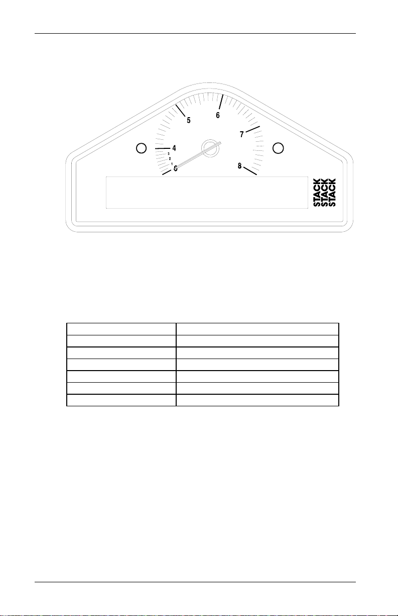
Displ ay Layer 1
6
5
7
4
3
2
1
0
8
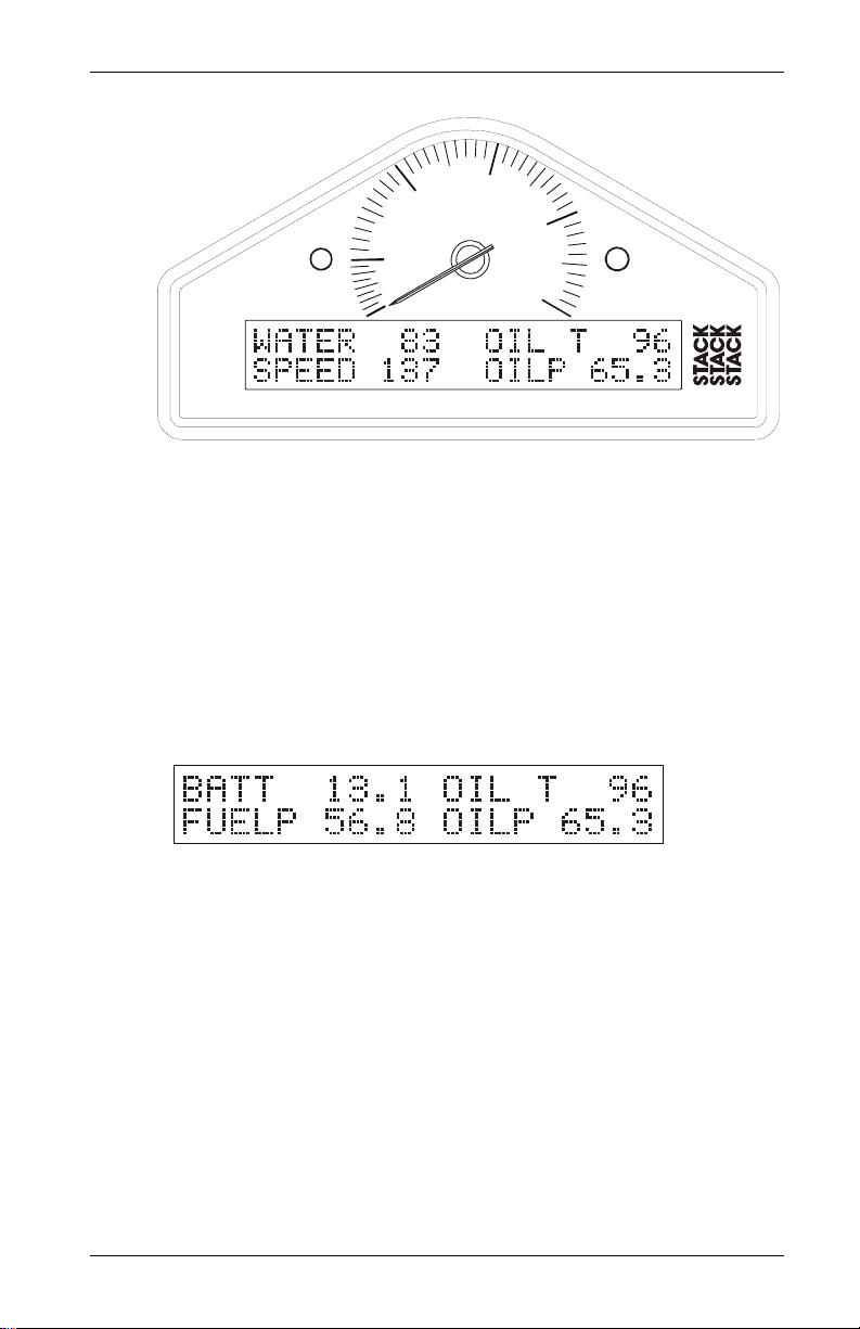
Display layer 1 shows:
• Water Temperature (WATER)
• Oil Temperature (OIL T)
• Current speed (SPEED)
• Oil Pressure (OILP)
Press Switch 3 to change the display to layer 2.
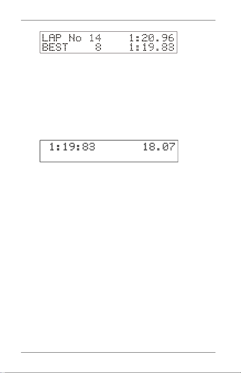
Displ ay Layer 2
Display layer 2 shows:
• Battery voltage (BATT)
• Oil Temperature (OIL T)
• Fuel Pressure (FUELP)
• Oil Pressure (OILP)
Press Switch 3 to change the display to layer 3.
Race Dash Users Guide 7
Page 14
Chapter 3. Operating the Display System
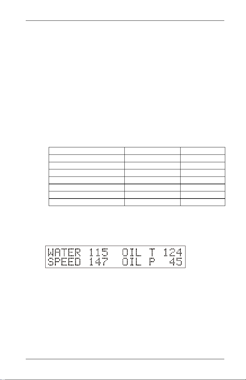
Displ ay Layer 3
Display layer 3 shows:
• Lap number of the last completed lap
• Lap time for the last completed lap
• Lap number of the fastest lap
• Fastest lap time (BEST)
Press Switch 3 to change the display to layer 4.
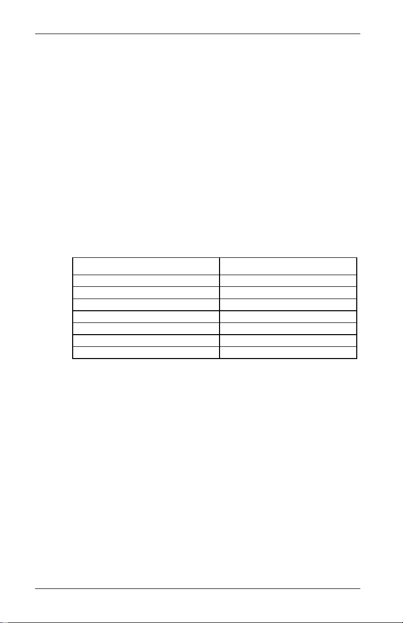
Displ ay Layer 4
Display layer 4 shows
• Fastest lap time
• Running time from the start of the current lap
Press Switch 3 to change the display back to layer 1.
8 Race Dash Users Guide
Page 15
Chapter 3. Operating the Display System
Peak Values (Tell Tales)
The system can display the peak values (sometimes called ‘telltales’) that have been recorded during a run for all the monitored
parameters.
Peak values are updated only when the engine speed has
exceeded its "gate value" for RPM for at least one second. This
allows the values to stabilize. Blipping the engine may not be
enough to update the peak values. The gate value is a predefined
RPM value that is used to control when the system updates the
peak values. This is to prevent abnormal peak values from being
recorded when, for example, the engine is either not running, is
idling or is being warmed up.
The system stores either a maximum or a minimum value as the
peak value, depending on the parameter, as follows:
Parameter Type of Peak Value Gated to RPM
Engine Speed (RPM) Maximum Yes
Oil Temperature Maximum Yes
Water Temperature Maximum Yes
Oil Pressure Minimum Yes
Fuel Pressure Minimum Yes
Battery Voltage Minimum Yes
Wheel Speed Maximum Yes
Displaying the Peak Values
Press and hold Switch 1 to show the peak values for the
parameters currently being displayed. Release the switch to
return to the normal display.
Race Dash Users Guide 9
Page 16
Chapter 3. Operating the Display System
Resetting the Peak Values
You can reset all of the peak values, except the fastest lap time,
manually. All peak values are reset at the same time. If the
engine is running at or above its gate value when the peak
values are reset, they are set to the current value of each
performance parameter.
To reset the peak values:
• Press and hold Switch 1 to display the peak values.
• While holding Switch 1, press and hold Switch 3.
• With Switch 3 held down, you will see the display revert to
the current values. The new peak values that are stored are
those being displayed when you release Switch 3.
If the engine is running below its gate value, the peak values are
not reset to the current values but are set to the values in the
following table:
Parameter New Peak Value
Engine RPM 0 RPM
Wheel speed 0 MPH
Oil Pressure 999.9 PSI
Fuel Pressure 99.99 PSI
Oil Temperature 0ºF
Water Temperature 0ºF
Battery Voltage 26.0V
Peak Value Memory
The peak values are stored in a memory that is powered by an
internal back-up battery. They remain stored in this memory
when the external power source is disconnected from the system.
The system needs to be returned to Auto Meter every 4-5 years
for the internal battery to be changed. An alarm is triggered when
the power from this battery drops below a safe level and the
warning “MEM BATT” is displayed.
10 Race Dash Users Guide
Page 17
Chapter 3. Operating the Display System
Alarms
The Display System has built-in warnings to alert the driver
when certain parameters either exceed or fall below their alarm
values. For example, a warning is signalled if the fuel pressure
falls below its alarm value or if the oil temperature rises above its
alarm value. You can adjust the preset alarm levels when you
configure the Display System. See Chapter 4, Configuring the
Display System in this manual.
Some of the warnings (see the following table) are triggered only
while the engine speed exceeds its "gate value" for RPM for at
least one second. Blipping the engine should not be enough to
trigger a warning. The gate value is a predefined RPM value that
is used to control when the system is to trigger a warning. This
is to prevent abnormal warnings from being triggered when, for
example, the engine is either not running, is idling or is being
warmed up.
(The oil pressure alarm will come on at power-up until the
engine is started and pressure exceeds the threshold set for the
alarm.)
The Display System has the following built-in alarms:
Parameter Alarm is triggered when the: Gated to RPM
Oil Temperature Current value exceeds the preset
value
Water Temperature Current value exceeds the preset
value
Oil Pressure Current value drops below the
preset value
Fuel Pressure Current value drops below the
preset value
Battery Voltage Current value drops below the
preset value
Yes
Yes
No
Yes
No
Race Dash Users Guide 11
Page 18

Chapter 3. Operating the Display System
Displaying an Alarm
When an alarm condition occurs, the built-in amber warning
light turns on and the digital display gives a warning message to
show the type and value of the alarm.
If you are using the External Alarm Warning Lamp, that lamp
will illuminate at the same time.
6
5
7
4
3
2
1
0
8
Clearing an Alarm
Press Switch 2 or Switch 3 while the alarm is being displayed.
Showing the Last Alarm
Press and hold Switch 2.
12 Race Dash Users Guide
Page 19

Chapter 3. Operating the Display System
Lap Times
The lap time is displayed for a preset time either when triggered
by the infra-red lap time sensor passing the lap time beacon or
when the driver presses Switch 4
You can adjust the preset display time when you configure the
Display System. See Chapter 4, Configuring the Display System
in this manual.
The most recent lap time is held in display layer 3. Press switch 3
to see this display layer. This display gives you the lap number
and time of the last recorded lap.
Resetting the Lap Time to Zero
Press and hold Switch 1 and then press Switch 4 to reset the lap
count and lap time to zero.
Race Dash Users Guide 13
Page 20

Chapter 3. Operating the Display System
Gear Shift Light
The gear shift light comes on when the engine RPM exceeds a
predefined value. See Chapter 4, Configuring the Display
System for information about setting this value.
If you purchased the optional Shift Light (model no. 9580) that
light will illuminate at the same time.
6
5
7
4
3
2
1
0
8
Making a Recording
All of the displayed parameters are recorded including the Lap
Times.
Data recording starts when the Engine Speed rises above a preset
RPM value. That value can be configured as described in
Configuring the Display System below. Recording stops when
the Race Dash is switched off or after the Engine Speed has been
at zero (engine not running) for more than five seconds.
The Race Dash can hold up to fifteen Runs; about two hours of
data. Recorded data can be deleted from the Playback Menu (see
next page).
14 Race Dash Users Guide
Page 21

Chapter 3. Operating the Display System
Playback Menu
The Playback Menu is displayed by holding down Switch
3 while the dash is powered up. The most recent run
will be selected, eg,
The top line of the display shows the currently selected run, the
maximum number of runs recorded and the duration of the
selected run.
The bottom line shows the number of laps in the run and the best
lap time.
Select the run which you wish to reply using Switches 1 and 2 to
scroll through the available runs. Then press Switch 4 to start
replaying.
The Playback Menu will not be displayed if the Engine Speed is
running, ie, RPM is above zero.
A summary of the switch actions is shown in the table below:
Switch Action
1 Select the previous run
2 Select the next run
3 No action; used to enter Playback mode at
power-up
4 Play the selected run;
if there are no runs, it won't play
1 & 3 Delete all the runs (see Note below)
A confirmation is required before the runs are deleted; press
Switch 1 to cancel and Switch 2 to confirm. Once the runs are
deleted, the number of runs will show zero.
Exit from Playback Mode by switching off the power. If Switch
3 is not held when the power is restored, the unit will revert to
Normal display mode.
Race Dash Users Guide 15
Page 22

Chapter 3. Operating the Display System
Replaying the Recorded Data
Once the selected run is replaying, the display layers work in the
same way as they did when the run was being recorded.
You may press Switch 4 at any time to pause the replay.
Pressing either Switch 1 or 2 will nudge the replay forwards or
backwards by the preset number of seconds.
A summary of the switch actions is shown in the table
below:
Switch Action
1 Nudge replay backwards XX seconds
2 Nudge replay forwards XX seconds
3 Change to next display layer or cancel a
displayed message
4 Toggle Pause function; press once to pause,
press again to restart
1 & 4 Exit back to the Run Selection Menu before the
replay has finished.
It is not possible to display peak values during the replay. The
original peak values are retained for viewing in Normal Mode.
The number of seconds which the replay can be nudged forwards
or backwards can be set in the Configuration Menus. The
default is ±10 seconds. The switches do not auto-repeat so, for
example, going forwards 40 seconds will require Switch 2 to be
pressed four times. Pressing the nudge switches will cancel any
displayed message before performing the nudge.
The display will change to a Run Navigation display while
Switches 1, 2 or 4 are held, showing the switch function and the
time position in the run.
Once the selected run has finished replaying, the Run Selection
Menu will be redisplayed.
16 Race Dash Users Guide
Page 23

Chapter 4. Configuring the Display System
Chapter 4. Configuring the Display
System
System Configuration Mode
You put the Display System into System Configuration Mode by
pressing Switches 1 and 2 together. You then work through the
configurable parameters in a preset sequence, pressing Switch 3
to display the next configurable parameter.
Setting or resetting configuration values
Use Switch 1 to decrease the value being configured and Switch
2 to increase it. The rate at which the value increases or
decreases accelerates while the switch is being held down.
Examples of the displays for each of the configuration items are
shown below.
Wheel circumference:
Set the value for the wheel circumference in the units of
measurement indicated.
Wheel speed pulses:
Set the value to the number of ferrous targets that the wheel
sensor is to count for each wheel revolution.
Engine speed cylinders:
Set the number of cylinders for the engine (for RPM).
Race Dash Users Guide 17
Page 24

Chapter 4. Configuring the Display System
Gate RPM:
Set the RPM above which peak values are stored and the Fuel
Pressure, Oil Temperature and Water Temperature warnings
operate.
Recording RPM:
Set the RPM at which the recording option is started.
Shift RPM:
Set the RPM at which the shift light is to come on.
High water temperature:
Set the value above which the water temperature alarm will
occur.
High oil temperature:
Set the value above which the oil temperature alarm will occur.
18 Race Dash Users Guide
Page 25

Chapter 4. Configuring the Display System
Low fuel pressure:
Set the value below which the fuel pressure alarm will occur.
Low oil pressure:
Set the value below which the oil pressure alarm will occur.
Low battery voltage:
Set the value below which the battery voltage alarm will occur.
Lap time pop-up:
Set the time in seconds for which the Lap Time pop-up will be
displayed when the vehicle passes the lap time beacon.
Recording RPM:
Set the RPM at which recording starts. Press Switches 1 and 2
together to disable and re-enable recording.
Race Dash Users Guide 19
Page 26

Chapter 4. Configuring the Display System
Nudge Amount:
Set the number of seconds, in increments of 10 seconds, by
which you want to skip through the data when either of the
Nudge Keys are pressed (see Replaying the Recorded Data
below). We suggest that you use a small value for tracks which
contain short laps and a larger value for longer circuits.
Switching Alarms on or off
You can enable (switch on) or disable (switch off) each of the
alarm warnings by pressing and holding Switch 1 and then
pressing Switch 2.
Note that you might change the preset value of the parameter
slightly while pressing both switches. This does not matter if you
are switching the alarm warning off and, if necessary, you can
correct the preset value after you switch it on again.
Leaving Configuration mode
When you wish to return to the normal display, press Switch 4.
20 Race Dash Users Guide
Page 27

Chapter 5. Installing the Display System
Chapter 5. Installing the Display System
Who can install the Display System?
The Display System can be installed by anyone competent in
fitting electrical and mechanical accessories to cars.
Tools Needed to Install the Display System
No special tools other than normal workshop tools are needed.
Preconfigured Display Systems
Use the instructions in the previous chapters to set up, operate
and configure the display before installing it in the vehicle.
Race Dash Users Guide 21
Page 28
Chapter 5. Installing the Display System
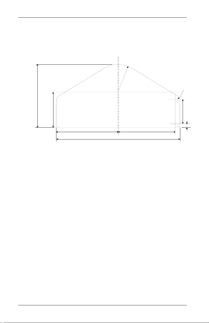
Fitting the Display Module
The Display Module is fitted into a cut-out in the instrument
panel/dashboard and secured using the two U-brackets at the
rear. The dimensions for the cut-out are shown below. A full
size template can be found in Appendix A.
97mm
(3.82 in.)
42.5mm (1.67 in)
Rad. Typ.
5.5mm (0.22 in)
Rad. Typ.
54.5mm
(2.15 in.)
95mm (3.74 in.)
190mm (7.48 in.)
89.5mm (3.52 in.)
Positioning the Display Module
Ensure that there is sufficient space behind the cut-out to allow
the wiring harness to be connected to the 19-way connector
without any tight bends to the wiring near the connector.
The Display Module must be positioned on the dashboard so that
the driver can see it, either over the steering wheel or through it.
The Display Module should be aligned so that the driver looks at
it square or from slightly above or below.
37.5mm
(1.48 in.)
5.5mm
(0.22 in.)
22 Race Dash Users Guide
Page 29
Chapter 5. Installing the Display System
Switches
The four switches are used to control the functions of the Race
Dash.
The normal functions of the four switches are:
Switch Functions
Switch 1
Switch 2
Switch 3
Switch 4 Manual Lap Marker
You can install the switches in any convenient location. When
installing the switches, you should take account of the following
considerations:
• The cable for each switch is approximately 16” in length
• It is important that the driver is able to reach Switch 3
• When you configure the system, you use Switches 1 to 4
1. Show Peak Values
2. Freeze speed on “HOLD” display (optional Corner Speed
feature only)
1. Show Last Alarm or
Enter Lap Time Memory mode (optional)
2. Clear Alarm
1. Change Display Layer
2. Clear Alarm
from the 19-way military connector.
easily in order to change the display and clear warning
messages after alarms. This switch is normally fitted on
the steering wheel.
for selecting the parameters and setting their values. These
switches should be installed so that you can reach them
easily when you are viewing the digital display.
Race Dash Users Guide 23
Page 30

Chapter 5. Installing the Display System
Warning Lights
The Race Dash has two built-in warning lights. One of these is
for the shift light and the other for warning the driver that an
alarm has been triggered.
As an option, you can install additional external warning lights
for these functions. External warning lights should be installed in
any position that is in the driver’s direct line of vision as they
need to be visible at all times.
Auto Meter can supply suitable external warning lights for
installation in the dashboard as well as shrouded versions that
can be mounted on top of the dashboard.
If you are using your own warning lights, ensure that the bulb
rating does not exceed 2 Watts; otherwise the Race Dash will be
damaged. If you need to use lamps greater than 2W, connect
them to relays and use the output sockets from the Race Dash to
switch these relays.
Engine Speed (RPM) Measurement
The engine speed (RPM) is measured by connecting the engine
speed wire directly to the ignition system. A single wire, with the
label ES, connects the Race Dash to the ignition system or lowtension negative side of the coil (see warning on the next page).
24 Race Dash Users Guide
Page 31

Chapter 5. Installing the Display System
Connecting the Display System to the
Ignition System
The Display System can be connected to engines with a variety
of ignition systems. Please see below.
* WARNING
Warranty will be void if connected to coil when using an
aftermarket ignition box such as, but not limited to products
from the following manufacturers: MSD, Crane, Jacobs,
Mallory, Holley, Etc.. Prior to installation, check with the
ignition box manufacturer for recommended tachometer
signal location.
See autometer.com/tech_installation.aspx
information.
The following connections are shown in greater detail:
• Series Resistor Connection
• ECU Connection (+ Pull-up resistor)
The connection of the Display System to these types of ignition
system is described on the next page:
for specific vehicle
Race Dash Users Guide 25
Page 32

Chapter 5. Installing the Display System
,
Series Resistor Connection
For systems which require series resistor on the ES (Engine
Speed Wire) the resistor must be connected directly to the
terminal to limit interference from the spark plug and coil wires
(which must be the shielded type).
Ignition
System
Resistor
ES (Engine
Speed) Wire
-
CB SW
+
Electronic Ignition or ECU Connection
Connect the ES (Engine Speed) wire directly to the “Tacho”
output of the electronic ignition or ECU. If this results in a Zero
RPM reading with the engine running then …
Some ECU’s (GM LS-1) require a Pull-up resistor connected
between the ES wire & +5v (reference wire). Resistor value of
10,000 Ohms is required.
ECU
Tacho o/p
+5v
Resistor
10
000 Ohms
ES
26 Race Dash Users Guide
Page 33

Chapter 5. Installing the Display System
Pressure Sensors
Fitting the pressure sensors
The system is supplied with two 150 psi pressure sensors to
measure Oil Pressure and Fuel Pressure. These sensors have a
1/8” NPTF thread.
Optional adapters may be supplied to match the pressure ports of
different types of engines.
If you find that you have a sensor with an incorrect thread, please
contact Auto Meter for advice.
Installing the pressure sensors
• Position each sensor and its cable as far as possible from all
sources of intense heat and from the ignition HT leads.
• Each sensor can be either screwed in directly to the
monitoring point or fitted separately by using a suitable
pressure hose to connect it to the monitoring point.
• Do not screw the sensor directly into the engine block, as
excessive vibration from some racing engines can affect the
long-term life of the sensor.
• Do not over-tighten the sensors.
Race Dash Users Guide 27
Page 34

Chapter 5. Installing the Display System
Temperature Sensors
The Race Dash is supplied with two temperature sensors with
1/8” NPTF thread. Each sensor can be used for monitoring both
oil temperature and water temperature.
Fitting the temperature sensors
• Position the sensors and their cables as
far as possible from sources of intense
heat and from the ignition HT leads.
• Mount each temperature sensor directly
in the appropriate fluid line. Screw the
sensor into a suitable mounting boss, so
that its end lies in the middle of the flow
of fluid.
28 Race Dash Users Guide
Page 35

Chapter 5. Installing the Display System
A
VSS Pulse Amplifier Interface
Introduction
This amplifier is designed to convert the output of an existing
sensor, which generates a pulsed signal which is not compatible
with the system’s channel input requirements. This
incompatibility may be caused by insufficient voltage or lack of
output current drive capability.
The amplifier has negligible loading effect on the signal and
includes the facility to adjust its sensitivity, so can be used with a
wide variety of sensors.
WARNING! For reasons of safety, NEVER
connect the amplifier to an ABS speed sensor.
Installation
Mounting
The amplifier should be mounted, using the self-adhesive dual
locking material supplied, in a position away from strong sources
of heat and H.T. leads. It should be noted that this adhesive will
not reach full strength for up to 24 hours.
On one side of the module there is a small red LED and a
potentiometer access hole. This potentiometer is used to alter the
sensitivity and the LED is used to give visual confirmation of
correct adjustment. Access to this part should therefore be
considered when choosing a mounting position.
To Vehicle Speed
Extension harness
To “WS” on
harness
djustment
screw
Race Dash Users Guide 29
LED
Page 36

Chapter 5. Installing the Display System
Using the 'dual-lock' fastener with Auto Meter sensors
This is a high opening force 'Velcro-type' fastener system with
identical mating halves. It is intended to be used for semipermanent fixing applications and is not intended for frequent
dismantling.
For best performance, the following precautions should be taken:
Bond strength is dependent upon the amount of adhesive to
surface contact development. Firm application pressure develops
better adhesive contact and thus improves bond strength.
To obtain maximum adhesion, the bonding surfaces must be
clean, dry and well unified. Typical surface cleaning solvents
are isopropyl alcohol/water mixture (rubbing alcohol) or
heptane. Use proper safety precautions when handling solvents.
Ideal application temperature range is 70-100ºF. Initial
application to surfaces at temperatures below 50ºF is not
recommended because the adhesive becomes too firm to adhere
readily.
To mount a sensor or housing on the vehicle
Take one of the supplied pieces of 'dual-lock' fastener, remove
the adhesive backing and attach to the sensor or housing.
Take a second strip of the fastener and attach to the first piece by
pushing them together firmly, ensuring correct alignment.
Remove the adhesive backing off the second strip of fastener and
attach the sensor or housing to the vehicle in the desired position.
Push against the fastener firmly to ensure maximum adhesion.
Do not try to separate the 2 strips of fastener immediately
The acrylic adhesive backing should be given 24 hours to
achieve full bond strength.
If you require further fastener strip or have any comments,
questions or recommendations regarding its use, please contact
Auto Meter or your nearest distributor.
30 Race Dash Users Guide
Page 37

Chapter 5. Installing the Display System
Electrical
The amplifier connects into the system via a four way Mini Sure
Seal (MSS) socket, the larger of the two connectors on the
amplifier. Use the extender cable supplied to connect the
amplifier to the WS input on the harness.
Use the vehicle speed extension harness with a MSS connector at
one end and two wires at the other to connect the amplifier to the
speed sensor.
For a two wire sensor, connect sensor wires to the white and
black wires on the cable.
For a three wire sensor, such as 5291 & 5292, connect black wire
to common ground with sensor and connect the white wire to the
sensor signal.
Adjustment
Once the system has been fully wired power should be applied.
At this stage it is desirable to arrange for the sensor to generate a
low frequency signal by spinning the wheel slowly. The red LED
at the end of the amplifier should be seen to flash as each signal
is received. If the frequency is higher than approximately 10
flashes/second the LED may only appear to dim, as the flashing
is too fast for the eye to see.
If this does not happen (the LED is always on or off) it will be
necessary to adjust the input sensitivity of the amplifier to match
the sensor. This is accomplished by turning the small screw
head, which is recessed, in the hole adjacent to the LED. This
should be adjusted until the LED flashes consistently.
The operation should be checked at the lowest possible
frequency, as this is the most likely speed for problems to occur.
Following these adjustments, correct operation can be verified by
observing the LCD speedometer at a range of speeds.
Race Dash Users Guide 31
Page 38

Chapter 5. Installing the Display System
VSS Pulse Amplifier Technical Specification
Supply : From system input
Output characteristics : compatible with system
Input impedance : >50K Ohms
Operating temperature range : -4 to 176 ºF
Input threshold adjustment range : -5 Volts to +12 Volts
Input hysteresis : +/- 0.1 Volt
Maximum input frequency 2000 Hertz
Physical dimensions : (mm) L 51, H 18, W 32
(in) L 2, H ¾, W 1¼
Weight : 50g / 2oz maximum
Vibration testing : 20 G, 50Hz to 2000Hz,
1 Octave/min for 12 hours
32 Race Dash Users Guide
Page 39

Chapter 5. Installing the Display System
Lap Timing Sensor (optional)
The lap timing sensor is actuated by an infra-red beacon
positioned at the side of the circuit. The sensor is fixed to a rigid
bracket mounted at a convenient position on the outside of the
vehicle where it is able to detect the signals from the beacon.
• It is secured by two nuts with M18 x 1mm threads.
• This sensor must be positioned horizontally and square to
the axis of the vehicle.
• In order to detect the signals from the beacon, it must be
situated outside the vehicle.
• It should, if possible, be positioned so that other vehicles
that are being overtaken (or are overtaking) at the moment
your vehicle passes the beacon do not block the signal.
After detecting a signal, the system does not recognise any
further signals from beacons for a period of ten seconds.
Race Dash Users Guide 33
Page 40

Chapter 5. Installing the Display System
Trackside Infra-Red Lap Beacon (optional)
The trackside infra-red lap beacon has a threaded socket on its
base for mounting to a standard photographic tripod. It should be
located as follows:
• As near to the start-finish line as possible
• At the same height as the on-vehicle detector
• Level, so that it emits a horizontal beam
• It must be between 6 and 95 feet from the vehicle when the
vehicle passes it
• Avoid positioning it so that the sun is directly behind it
when it is being used.
• Where the unit is to be used for lengthy periods in very
hot, sunny conditions, it should be protected by shading it
from direct sunlight.
• Do not allow water to be sprayed onto the transmitter
lenses. During wet conditions, fit a protective shroud over
the beacon. Do not cover the beacon, for example using a
plastic bag.
34 Race Dash Users Guide
Page 41

Chapter 5. Installing the Display System
Power supply to Trackside beacon
The beacon operates from a 12v DC supply. A sealed lead-acid
battery with a minimum rating of 2.5 Amp/hour is recommended.
This provides about 15 hours of operation.
The condition of the battery is indicated by the color of the LED
indicator on the front panel of the unit
Green The voltage is, at present, adequate for use
Red The voltage is too low (replace the battery).
No Color Battery exhausted or disconnected.
Wiring harness
The Race Dash and the sensors, switches and external lights for
your Display System are connected together by means of the
wiring harness supplied with the system.
The wiring harness can be fitted after the Race Dash and all the
sensors and switches have been installed.
This harness has been designed so that the various branches are
long enough for most applications. Occasionally, an individual
branch may need to be extended significantly. Contact Auto
Meter or your Auto Meter dealer to purchase extension cables.
Do not shorten the supplied wire harness. It is recommended that
additional length is coiled and secured away from moving parts
and high heat sources.
Extender wires for connecting the air temperature and wheel
speed sensors to the wiring harness are available in lengths of
either 2’, 4’ or 6’.
Model No. Length
9524 2’
9525 4’
9526 6’
Race Dash Users Guide 35
Page 42

Chapter 5. Installing the Display System
Fitting the wiring harness
When fitting the harness on the vehicle, you should observe the
following:
• Start by attaching the harness to the Race Dash by
connecting the 19-way military connector.
• First position the ends of all the wires at the locations of the
sensors, lamps and switches to which each is to be
connected, but do not connect them yet.
• All wires should be as far as possible and not less than 2”
from sources of electrical noise such as ignition HT leads,
distributor caps etc.
• When you pass any wire through a bulkhead or dashboard,
fit a cable gland into the hole so that the edge of the hole
cannot chafe the wire.
• Particular care is needed when passing wires through holes
in carbon fiber, as the carbon can cut through cables very
easily.
• The heatshrink sleeving around the sensor cables can be cut
back, if necessary, to enable the sensor cables to go in
separate directions earlier. It is recommended that you
always leave at least 6” of heatshrink sleeving to provide
additional strain relief for the cable where it enters the 19way connector.
• Connect the wires when all the sensors are in position and
you have secured the wiring harness.
Wiring labels
See Chapter 2 if you need to check the labels used to identify
the individual cables in the wiring harness
Checks and Alarms
You should check the system to ensure that all the sensors are
detecting the correct values. You should also run the engine up
to its operational levels to check that the values displayed by the
Display System are accurate. You should then check out the
alarm systems to ensure that they are functioning correctly
before going out for a test drive.
36 Race Dash Users Guide
Page 43

Chapter 6. Troubleshooting
Chapter 6. Troubleshooting
Symptom Possible Cause Remedy Notes
Display is dead
(no backlight,
nothing on
display, no green
dial lights)
Display is dead
(no backlight,
nothing on
display, green dial
lights on but dim)
or
!! LOW BATT !!
warning on
display
Display flashes
and dial pointer
resets or vibrates
The
!! LOW OIL P !!
message does
NOT appear on
power up.
The warning light
is not turned on.
Ignition is off Turn ignition on
Battery is dead Recharge or
Power connection
to B + or B - is
faulty
Battery is almost
dead
Power connection
to B + or B - is
faulty
Battery is almost
dead
Power connection
to B + or B - is
faulty
Pressure sensor
has failed
Sensor
connections are
faulty
Oil pressure alarm
disabled
replace battery
Check if battery is
connected
correctly. Check
power lead
continuity
Recharge or
replace battery
Check power lead
continuity
Recharge or
replace battery
Check power lead
continuity
Replace sensor Swap the fuel
Check for
continuity on
sensor lead.
Check that the oil
pressure alarm is
set on
The power lead is
labeled B+ & B-
The battery positive
lead B+ is 19w conn
pin G.
B- is 19w connector
pin H.
pressure sensor to
confirm fault
A reading of 999 on
the display indicates
an open circuit
connection (pin D to
the red sensor lead
and pin H to the
black sensor lead)
Race Dash Users Guide 37
Page 44

Chapter 6. Troubleshooting
Symptom Possible Cause Remedy Notes
Display gives a
fixed temperature
reading of 999° F
Faulty sensor
Display gives a
fixed temperature
reading of 0°F
when the engine
temperature is
above 55°F
reading of
999.9 PSI
Fixed pressure
reading of
-99.9 PSI
Fixed pressure
reading of 0.0 PSI
or suspected
low/slow reading
Temperature
sensor has failed
connections
A temperature
sensor has failed
Faulty sensor
connections
Pressure sensor
has failed
Faulty sensor
connections
Pressure sensor
has failed
Faulty sensor
connections
Pressure sensor
has failed
Faulty sensor
connections
Replace sensor
Check the
continuity of
sensor leads
Replace sensor Disconnect sensor
Check continuity
of sensor leads
for open circuits.
Replace sensor Fixed pressure
Check continuity
of sensor leads
for open circuits.
Replace sensor Disconnect sensor.
Check continuity
of sensor leads
for short circuits
Replace sensor Swap with the other
Check pressure
connections
Disconnect sensor.
If reading changes
to 0, replace sensor.
Otherwise check
harness for short
circuit
and short its lead
together. I fthe
reading changes,
replace the sensor.
Check the wiring
harness for open
circuits (pin E to the
red OT sensor wire,
pin P to the red WT
wire and pin H to
both the black OT
and WT sensor
wires)
Pin D to the red OP
wire, pin R to the
red F wire and pin H
to both the black OP
and F sensor wires
If reading changes
to 999, replace
sensor
Check the wiring
harness for short
circuit
pressure sensor to
confirm fault
Check plumbing for
a blockage (kinks in
flexible hoses)
38 Race Dash Users Guide
Page 45

Chapter 6. Troubleshooting
Symptom Possible Cause Remedy Notes
All sensors show
fixed high values
Faulty switch wiring Check switch wiring Check wiring for short
Displays pressure
values too low and
temperature values
too high
Sensor reading
incorrect
Peak values not
updated
Switch 1: Show
peak values does
not work
Switch 2: Show last
alarm function does
not work
Switch 3: Change
display layer
function does not
work
Switch 1 (Peaks)
faulty
Low Battery voltage Recharge battery The system does not
Another gauge
connected to sensor
Gate value set too
high
Internal memory
battery dead
Switch 1 faulty Replace switch Disconnect switch and
Faulty switch wiring Check switch wiring
Switch 2 faulty Replace switch Disconnect switch and
Faulty switch wiring Check switch wiring
Switch 3 faulty Replace switch Disconnect switch and
Faulty switch wiring Check switch wiring
Replace switch Disconnect switch. If
Disconnect other
gauge
Change Gate RPM
in the display
configuration menu
Return unit to Auto
Meter for new
battery service
for correct continuity
for correct
continuity.
for correct
continuity.
values return to
normal, replace switch.
between connector
pins K and H (earth)
give accurate readings
when voltage is below
9.0V
It is not permissible to
connect a second
gauge
Peak values only
updated while the
engine RPM is greater
than the Gate value
Display shows
“!! MEM BATT !!”
warning on power up
short its leads. If
display changes,
replace Switch 1
Otherwise check
wiring.
Pin K to red S1 wire
less than 1.0 Ohm and
Pin K to Pin H (ground)
greater than 1M Ohm
short its leads. If
display changes,
replace Switch 2
Otherwise check
wiring.
Pin L to red S2 wire
less than 1.0 Ohm and
Pin L to Pin H (ground)
greater than 1M Ohm
short its leads. If
display changes,
replace Switch 3
Otherwise check
wiring.
Pin U to orange S3
wire less than 1.0 Ohm
and Pin U to Pin H
(ground) greater than
1M Ohm
Race Dash Users Guide 39
Page 46

Chapter 6. Troubleshooting
Symptom Possible Cause Remedy Notes
Switch 4: does
not set or
display pop-up
lap times when
no automatic
receiver in use
Faulty switch
Lap time is not
displayed
automatically
(Automatic
receiver is fitted)
External warning
light dead when
the display
warning light is
OK
External gear
shift light dead
Faulty wiring to
Switch 4 faulty Replace
wiring
Lap marker
receiver lead
faulty
Lap marker
receiver faulty
Bulb has burnt
out
Faulty wiring to
light
Bulb has burnt
out
light
switch
Check switch
wiring for
correct
continuity.
Check lap
marker wiring
Replace lap
marker
receiver
Replace bulb Swap with the
Check
continuity of
wiring.
Replace bulb Swap with the
Check
continuity of
wiring:
Disconnect the
switch and short
the leads
together. If the
display changes
replace Switch 4
Otherwise check
wiring.
Pin U to yellow
S4 wire less than
1.0 Ohm and Pin
U to Pin H
(ground) greater
than 1M Ohm
Disconnect
receiver and
press lap
Switch 4. If
display changes
replace receiver
after checking its
wiring.
other light to
confirm burnt-out
bulb. If not burnt
out, check wiring.
Pin G to red AL
wire less than 1.0
Ohm and Pin N to
yellow AL wire
greater than 1.0
Ohm
other light to
confirm burnt-out
bulb. If not,
check wiring
Pin G to red SL
wire less than 1.0
Ohm and Pin M to
green SL wire
greater than 1.0
Ohm
40 Race Dash Users Guide
Page 47

Chapter 6. Troubleshooting
Symptom Possible Cause Remedy Notes
Display values
and messages
unclear or
unreadable (poor
contrast)
No RPM speed
reading
Displayed RPM
value too high or
too low by a
constant %-age
amount.
reading erratic,
pointer jumps high
or low
Display too hot or
too cold
ECU interface
shorted.
Not normally fitted
Incorrect wiring Check the
System configured
with wrong number
of engine cylinders.
Ignition system
pulses per
revolution not same
as number of
cylinders
Incorrect wiring Reconnect the
Signal from ignition
system or coil is
noisy
Ensure that the
display is
operated within
the specified
temperature range
Check the two
core screen ECU
wires for short
circuits
connection of the
engine speed wire
to the ignition
system (or sensor,
if used)
Reconfigure
system to correct
number of
cylinders.
Reconfigure
system to correct
number of pulses
per revolution.
tachometer as
specified in this
manual
Condition the ES
signal by placing
a resistor in line
with the ES wire
Operating
temperature is
+5°F to +160°F
ECU wire is 300mm
inside the main
sensor leads sleeve.
Make sure that none
of the wire ends are
shorted
See instructions
supplied in this
manual. If
connected directly to
the coil, check that it
is to the switched
low tension side
(usually the negative
side).
Ignition systems may
either:
a) produce "waste"
sparks giving double
the number of
cylinders per
revolution
b) use multiple coils
where each
additional coil gives
proportionately fewer
pulses per
revolution.
Tachometer
Resistor values
(1/2W 5% 350v) 10K
ohms for dedicated
tacho output; 47K
ohms for coil
connection (nonCDI); 100K ohms for
CDI connection.
Race Dash Users Guide 41
Page 48

Chapter 6. Troubleshooting
Symptom Possible Cause Remedy Notes
value too high or
too low by a
constant %-age
amount.
No speed reading
Speed reading
erratic, value jumps
high or low
Speed reading dies
after a short time
No alarms for
water, oil or fuel
(temperatures and
pressures) being
displayed
Display and alarm
light flash when the
engine is running
System configured
with wrong number
of targets per wheel
revolution
System configured
with wrong wheel
circumference.
Faulty sensor
and/or wiring
Incorrect sensor
gap (too far apart
or too close)
Sensor and targets
moving apart
Ambient
temperature too
high
All the alarms have
been switched off
The engine RPM
gate value is set
too high
Intermittent alarm
caused by a
parameter with its
alarm level set too
close to the normal
operating value
Reconfigure the
system with
correct values
Typical wheel
Check sensor
indicator for
correct operation
Check that the
gap is
approximately
1mm
Fabricate a more
rigid sensor
bracket
Shield the
sensor from
radiated heat
from brakes and
bearings.
Insulate sensor
from conducted
heat with fibre
washers. Duct
cooling air
around the
sensor
Switch on the
required alarms
Reset the RPM
gate to a lower
value.
Either change
the value for the
alarm or turn the
alarm off
Displayed speed
circumference for a
car is 70” or 35” for a
kart
Rotate the wheel by
hand and check that
the sensor indicator
lights up as each
target passes the
sensor
Maximum
temperature for
correct operation of
the wheel speed
sensor is 175°F
Alarms only operate
when the engine is
running at the RPM
gate value or above
it.
Press Switch 2 to
see which sensor is
causing the alarm.
42 Race Dash Users Guide
Page 49

Chapter 6. Troubleshooting
Symptom Possible Cause Remedy Notes
Display and alarm
light flash when
the engine is
running
Display works OK
until engine starts
then Display
freezes or resets
continuously.
Display recovers
once engine
stopped.
Intermittent alarm
caused by a
parameter with its
alarm level set too
close to the normal
operating value
Interference from
Ignition system &
HT Leads
Dash wiring close
to HT leads & or
injector leads, or
HT leads tied to
isolated metal work
to which Dash
wiring is also tied.
Either change the
value for the
alarm or turn the
alarm off
Fit Suppressed
(Silicon) HT
Leads. Fit a
suppression
capacitor (2.2uF)
between the coil
(battery
connection) &
chassis
Run Dash wiring
away from HT
leads & injector
leads
Press Switch 2 to
see which sensor is
causing the alarm.
Use ‘Helical’
suppressed leads in
extreme cases
Recommended
Minimum spacing
3.0”
Race Dash Users Guide 43
Page 50

Appendix A. Template for the Display
Module
Use the template on the following page for cutting out an
aperture for the Display System.
Page 51

Page 52

Appendix C. Summary of Switch Functions
Appendix B. Wiring Harness Diagram
46 Race Dash Users Guide
Page 53

Appendix C. Summary of Switch Functions
Appendix C. Summary of Switch
Functions
Normal Operation
Functions Switch or Switches
Show Peak Values Switch 1
Change Display Layer Switch 3
Clear Alarm Switch 2 or Switch 3
Show Last Alarm or
Enter Lap Time Memory (optional)
Manual Lap Marker Switch 4
Reset Peak Values Switches 1 & 3 together
Reset lap count and lap time to zero Switches 1 & 4 together
Enter System Configuration Mode Switches 1 & 2 together
System Configuration Mode
Functions Switch or Switches
Decrease the value of the parameter
being displayed
Increase the value of the parameter being
displayed
Enable or disable an alarm for the
parameter being displayed
Display the next configurable parameter Switch 3
Quit configuration mode and return to
normal mode
Switch 2
Switch 1
Switch 2
Switches 1 & 2 together
Switch 4
Lap Time Memory Mode (optional)
Functions Switch or Switches
Show Previous Lap Time Switch 1
Show Next Lap Time Switch 2
Quit Lap Time Memory Switch 3
Race Dash Users Guide 47
Page 54

Appendix D. Service and Support
Appendix D. Service and Support
Service
For service send your product to Auto Meter in a well packed
shipping carton. Please include a note explaining what the problem
is along with your phone number. Please specify when you need
the product back. If you are sending product back for Warranty
adjustment, you must include a copy (or original) of your sales
receipt from the place of purchase.
48 Race Dash Users Guide
Page 55

Appendix D. Service and Support
12 Month Limited Warranty
Auto Meter Products, Inc. warrants to the consumer that all Auto
Meter High Performance products will be free from defects in
material and workmanship for a period of twelve (12) months from
date of the original purchase. Products that fail within this 12
month warranty period will be repaired or replaced at Auto Meter’s
option to the consumer, when it is determined by Auto Meter
Products, Inc. that the product failed due to defects in material or
workmanship. This warranty is limited to repair or replacement of
parts in the Auto Meter instruments. In no event shall this warranty
exceed the original purchase price of the Auto Meter instruments
nor shall Auto Meter Products, Inc. be responsible for special,
incidental or consequential damages or costs incurred due to the
failure of this product. Warranty claims to Auto Meter must be
transportation prepaid and accompanied with dated proof of
purchase. This warranty applies only to the original purchaser of
product and is non-transferable. All implied warranties shall be
limited in duration to the said 12 month warranty period. Breaking
the instrument seal, improper use or installation, accident, water
damage, abuse, unauthorized repairs or alterations voids this
warranty. Auto Meter Products, Inc. disclaims any liability for
consequential damages due to breach of any written or implied
warranty on all products manufactured by Auto Meter.
For Service Send To: AUTO METER PRODUCTS , INC.
413 W. Elm St., Sycamore, IL 60178 USA (866) 248-6357
Email us at service@autometer.com
http://www.autometer.com
Race Dash Users Guide 49
Page 56

Index
Index
additional external warning lights, 24
alarm for battery voltage, 11
alarm for fuel pressure, 11
alarm for oil pressure, 11
alarm for oil temperature, 11
alarm for water temperature, 11
alarm warning light, wiring label, 4
alarms, 11
alarms, switching on or off, 20
analog tachometer, 4
battery voltage, 7
battery voltage alarm, 11
checks and alarms, 36
clearing an alarm, 12
configuring the display system, 17
current speed, 7
digital display panel, 4
Display layer 1, 7
Display layer 2, 7
Display layer 3, 8
Display layer 4, 8
display layers, 6
Display module, 4
Display System, template, 44
Dual-Lock, 30
engine speed (RPM), 24
engine speed (RPM), wiring label, 5
external warning lights, additional, 24
fastest lap time, 8
fitting the display module, 22
fuel pressure, 7
fuel pressure alarm, 11
fuel pressure sensor, wiring label, 5
gate value, 9, 11
Installing the Race Dash, 21
labels on wiring, 4
lap number, 8
lap time, 8
lap times, 13
lap timing sensor, 33
lap timing switch, wiring label, 4
making a recording, 14
maximum water temperature alarm, 18
MSS connector, 31
oil pressure, 7
oil pressure alarm, 11
oil pressure sensor, wiring label, 5
oil temperature, 7
oil temperature alarm, 11
oil temperature sensor, wiring label, 5
operating the system, 6
optional components, 3
peak value memory, 10
peak values, 1
peak values (tell tales), 9
peak values, resetting, 10
Performance parameters, 1
playback menu, 15
power supply, 5
power supply to trackside beacon, 35
pressure sensors, 26
replaying the recorded data, 16
resetting the peak values, 10
RPM gate value, 9, 11
shift light, 1, 14
shift light, wiring label, 4
showing the last alarm, 12
standard components, 3
switch functions, summary of, 47
switches, 23
switching the system on, 6
tachometer, 4
temperature sensors, 28
Template for the Display Module, 44
tools needed, 21
trackside infra-red beacon, 34
unpacking, 3
Velcro. See Dual-Lock
VSS Pulse amplifier
adjustment, 31
connection, 31
installation, 29
specifications, 32
warning lights, 24
warning messages, 1
water temperature, 7
water temperature alarm, 11
water temperature sensor, wiring label, 5
wheel speed sensor, wiring label, 4
wires in the harness, labels, 4
Wiring harness, 4
extenders, 35
Wiring Harness Schematic Diagram, 46
wiring harness, installation of, 35
50 Race Dash Users Guide
 Loading...