

Page 1
12V BATTER Y
INSTALLATION INSTRUCTIONS
ELITE SERIES
FULL SWEEP ELECTRIC PYROMETER
2650-1459-00
Important
Pyrometers are sensitive, high accuracy instruments. They must be handled and installed with care to insure proper performance. Carefully read and
follow these instructions, and your pyrometer will provide you with a long and accurate life.
Pro Control
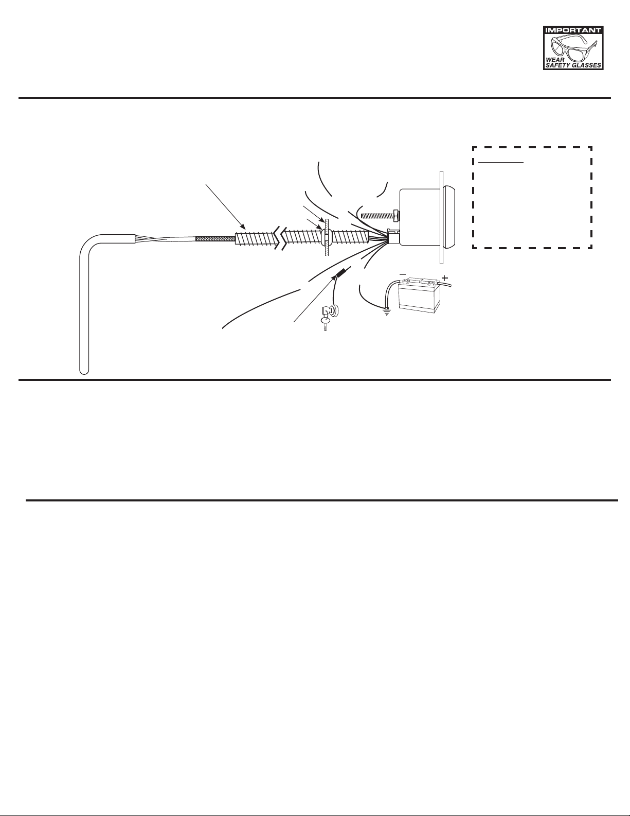
OPTIONAL SLIT TUBING RECOMMENDED
(AVAILABLE AT MOST HARDWARE STORES)
Pro Control
High Output #2
Firewall
Grommet
White
Low Output #1
Orange
Blue
Red
Black
Black
Pro Control
Ground
CAUTION:
As a safety precaution, the
+12V terminal of this product
should be fused before
connecting to the 12V ignition
switch. We recommend using
a 1 Amp, 3AG fast-acting type
cartridge fuse (Littlefuse® #
312 001 or an equivalent).
+12v Dash
Lighting
Important: See "Lighting Mode"
(See Caution Left)
Fuse
+12v Connection
Good Engine Ground
NOTE: When the ignition is off the pointer may not always rest at zero.
INSTALLATION
1. Check that you have all parts required for installation, and the engine is cool.
2. Disconnect the negative (-) battery cable.
3. Gauge mounts in a 2 1/16” hole. Use supplied brackets and nuts to secure gauge to dash.
4. Drill 1” diameter hole where wires pass through sheet metal (such as firewall) and install rubber grommet provided.
(Grommet will require slit.)
5. Connect the white wire to dash lighting or switchable 12v light source, red wire from harness to +12V terminal on
ignition switch or other +12V power source, and black wire to ground.
6. Reconnect negative (-) battery cable.
PROBE INSTALLATION
1. Begin by installing the thermocouple in the exhaust, then work back to the gauge. Installing the probe in the proper location will
insure optimal temperature readings. For non-turbo engines, install the probe 1-2 inches from the cylinder head.
For turbo engines, remove the exhaust manifold and install the probe 1-2 inches from the cylinder head. If the exhaust manifold
cannotberemoved,installtheprobe1-2inchesaftertheturboexhaustoutlet(Exhaustgastempscoulddropover200˚when
installing after the turbo). CLEAN ALL METAL FILINGS out of the exhaust manifold. Metal filings will damage the turbo impellor
if they go through the turbo.
The probe can be mounted in two different ways, so please use the method best suited for your needs.
A) Pre-existing 1/8” NPT Threaded Hole: Simply screw the threaded fitting into the hole, insert the probe, and tighten the set
screw snugly onto the probe. (Caution: do not over tighten set screw or damage to probe may occur.) Make sure the probe is
oriented so the wires do not come in contact with, or become too close to the manifold or other hot engine parts.
See illustration for details.
B) Stainless Clamp Method: This method is for applications that require frequent removal of the manifold or header for service,
or just faster and easier installation. Drill a 7/16” diameter hole about 6” down from the junction of the exhaust pipe to manifold
junction. Undo the clamp and slide the probe into the hole in the clamp. Slide the set screw collar onto the probe.
Before tightening the collar in position make sure that when inserted, the probe will have its tip in the middle two-thirds of the
exhaust stream. Tighten screw collar in position. (Caution: do not over tighten set screw or damage to probe may occur.)
Hold the clamp open when inserting the probe into the 13/32” hole. Re-join the clamp ends and tighten in position.
Make sure the probe is oriented so the wires do not come in contact with, or become too close to the manifold or other hot
engine parts. See the illustration below for details.
2. With the probe installed, the wire harness can now be routed to the gauge. The wire harness is an integral part of the pyrometer
calibration. It may not be shortened or lengthened without affecting the gauge calibration. You will need to determine a suitable
location to coil the excess wire, and tie it loosely with a wire tie. (Loosely tying the excess coil prevents embritlement caused by
vibration.) Pass the harness through the fire wall using an existing hole, or drill a 1” diameter hole and use the rubber grommet
provided to protect the wire from damage.
Page 2
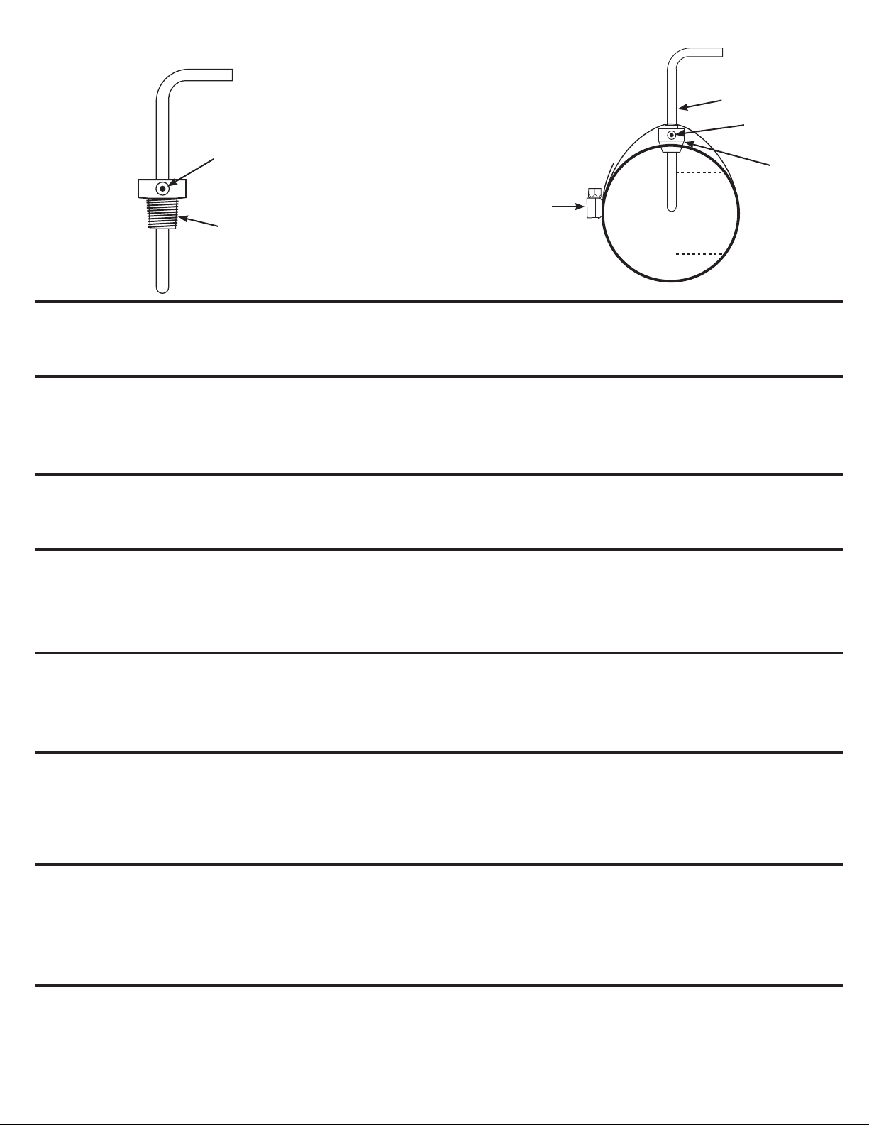
A. Pre-existing 1/8” NPT Threaded Hole
SET SCREW
B. Stainless Clamp Method
PROBE
SET SCREW
COLLAR
STAINLESS
CLAMP
1/8” NPT FITTING
middle 2/3
Power-Up
The pointer will move counter clockwise to the stop pin and then moves to the current gauge reading. This procedure is an auto-calibration function
and is performed on every power-up. While this test is being performed, the gauge may make a clicking sound. This is normal.
Peak Recall
Press and hold the PEAK button to recall the highest temperature reading since the memory was last cleared. To clear the memory, press and hold
the PEAK button, and while still holding the PEAK button, press the WARN button. The pointer will move to the stop pin to indicate that the memory
has been cleared. Release the PEAK and WARN buttons to resume normal operation. The peak recall point is retained when power is removed
from the gauge.
Full Dial Warning
This gauge features full dial warning. When a warning point is reached, the entire dial illuminates in the programmed warning color. This feature is
available for both a high and low warning set point. In addition, the warning color will flash when an over warn point is reached.
Pro Control High Warning Set Point
To adjust the high warning set point, press and release the WARN
button. The warning light will begin to flash and the pointer will move
to the previous high warning set point signifying that warning set
mode has been selected. Once in set mode, press the WARN button
to move the pointer down, or press the PEAK button to move the
pointer up. Three seconds after the last button press, the warning
light will stop blinking and the pointer will return to the current
reading. The warning set points are retained when power is removed
from the gauge.
Pro Control High Over Warn Set Point
To adjust the high over warn set point, press and hold the WARN
button. After three seconds the warning light will begin to flash and the
pointer will move to the previous high over warning set point signifying
that over warn set mode has been selected. Release the warn button.
Pro Control Low Warning Set Point
To adjust the low warning set point, press and hold the WARN button,
and while still holding the WARN button, press and release the PEAK
button. The warning light will begin to flash and the pointer will move to
the previous low warning set point signifying that warning set mode has
Pro Control Low Over Warn Set Point
To adjust the low over warn set point, press and hold the WARN
button, and while still holding the WARN button, immediately press and
hold the PEAK button. After three seconds the warning light will begin
to flash and the pointer will move to the previous low over warning set
Change Backlight Color
To change the backlight color:
With power off, press and hold the warning button. Apply power to
the gauge. Release the WARN button. Press and release the PEAK
button. The pointer will move to half scale and the dial will illuminate with
Once in set mode, press the WARN button to move the pointer down,
or press the PEAK button to move the pointer up. Three seconds after
the last button press, the warning light will stop blinking and the pointer
will return to the current reading. The over warn set points are retained
when power is removed from the gauge.
been selected. Once in set mode, press the WARN button to move the
pointer down, or press the PEAK button to move the pointer up. Three
seconds after the last button press, the warning light will stop blinking
and the pointer will return to the current reading. The warning set points
are retained when power is removed from the gauge.
point signifying that over warn set mode has been selected. Release
both buttons. Once in set mode, press the WARN button to move the
pointer down, or press the PEAK button to move the pointer up. Three
seconds after the last button press, the warning light will stop blinking
and the pointer will return to the current reading. The over warn set
points are retained when power is removed from the gauge.
the current Backlight Color. Press and hold the PEAK button to cycle
through the available colors. Once you have selected the desired color,
release PEAK and don’t press any buttons for about three seconds. The
dial will flicker white several times to indicate the desired setting has
been saved and the gauge will return to normal operation with your new
color selection. Color selections are saved when power is off.
Page 3

Change Low Warn Color
(Region A color)
Warn Color Set Mode:
With power off, press and hold the WARN button. Apply power to the
gauge. Release the WARN button. The pointer will be at the stop pin
and the dial illumination will be off. Press and release the WARN button
to cycle between HIGH warn color set and LOW warn color set modes.
In High Warn color set mode, the pointer will move to full scale and the
dial will illuminate with the current High Warn color. In Low Warn color
set mode, the pointer moves to the minimum position and the dial will
illuminate with the current Low Warn color.
To change Low Warn Color:
When the Low Warn color set mode has been selected (see above),
press and HOLD the WARN button to cycle through the available colors.
Once you have selected the desired color, release the WARN button.
Don’t press any buttons for about three seconds. The dial will flicker
white several times to indicate the desired setting has been saved and
the gauge will return to normal operation with your new Low Warn color
selection. Color selections are saved when power is off.
Change High Warn Color
(Region C color)
Warn Color Set Mode:
With power off, press and hold the WARN button. Apply power to the
gauge. Release the WARN button. The pointer will be at the stop pin
and the dial illumination will be off. Press and release the WARN button
to cycle between HIGH warn color set and LOW warn color set modes.
In High warn color set mode, the pointer will move to full scale and the
dial will illuminate with the current High Warn color. In Low Warn color
Lighting Mode
(Region B Color)
This gauge allows the dial lighting to operate in two modes, Full On or
Dimmable. Factory default is Full On.
Full On: In this mode, the white lighting wire is ignored. The gauge
dial lighting is always on at full brightness. (unless you select NO color
when setting the Backlight Color). If using Full On mode, white wire
hook-up is not needed.
Gauge Reset
It may be desired to reset the gauge. This clears programmable
settings to a system default. With power off, hold in both buttons.
Apply power to the gauge, wait two seconds, and release both buttons.
The dial face will flicker white several times and return to normal
operation. At this point, the gauge has been reset.
Reset Settings:
High Warning Set Point: Max Value
Low Warning Set Point: Lowest Value
set mode, the pointer moves to the minimum position and the dial will
illuminate with the current Low Warn color.
To change High Warn Color:
When the High Warn color set mode has been selected (see above),
press and hold the WARN button to cycle through the available colors.
Once you have selected the desired color, release the WARN button.
Don’t press any buttons for about three seconds. The dial will flicker
white several times to indicate the desired setting has been saved and
the gauge will return to normal operation with your new High Warn color
selection. Color selections are saved when power is off.
Dimmable: In this mode, the white wire is used to set the intensity of
the dial lighting from full brightness down to off.
To change the Lighting Mode:
With power off, press and hold the PEAK button. Apply power to the
gauge. Release the PEAK button and the dial face will illuminate with
either white lighting or blue lighting. Press and release the PEAK button
to toggle between Full On (dial is illuminated white) and Dimmable (dial
is illuminated blue). Once you have selected the desired mode, don’t
press any buttons for about three seconds. The dial will flicker white
several times to indicate the desired setting has been saved and the
gauge will return to normal operation with your new mode selection.
Mode selections are saved when power is off.
Peak: Lowest Value
High Warning Color: Red
Low Warning Color: Green
Backlighting Color: White
Lighting Mode: Full On
High Warning Pro Control State: Active High
Low Warning Pro Control State: Active Low
High Over Warn Set Point: Max Value
Low Over Warn Set Point: Lowest Value
Pro Control Active States
The active region for Pro Control outputs are user configurable. For
example, consider a pressure gauge with a low warning set point at
20 PSI . The gauge can be configured so the associated Pro Control
output is active when the pointer falls below the set point [less than 20
PSI] (active low) OR when the pointer is beyond the set point [greater
than 20 PSI] (active high). Likewise, consider a pressure gauge with
high warning set point at 95 PSI. Again, the gauge can be configured
so the associated Pro Control is active when the pointer falls below
the set point [less than 95 PSI] (active low) OR when the pointer
progresses beyond the set point [greater than 95 PSI] (active high).
To change the active state:
With power off, press and hold the PEAK button. Apply power to the
gauge. Release the PEAK button. Press and release the WARN
button. The gauge is now in Active State Set Mode. The pointer will
point straight up at the value in the top center of the dial. Press and
release the WARN button to toggle back and forth between the low and
high warning point active state modes. Doing so will cause the dial to
change back and forth between green and red. When setting the low
warning active state the dial face will be green. When setting the high
warning active state the dial face will be red.
Once the designated warning mode is selected (green or red) press and
hold the WARN button to toggle between active high and active low. As
you hold the button the pointer will continuously sweep from the left of
center and to the right of center pausing at each side. Left of center is
active low and right of center is active high. Release the WARN button
when the pointer is in the position of the desired active state. Once you
have selected the desired state, don’t press any buttons for about three
seconds. The dial will flicker white several times to indicate the desired
setting has been saved and the gauge will return to normal operation with
your new state selection. State selections are saved when power is off.
NOTE: The Pro Control Active State does not
affect the color of each dial region.
Page 4

Pro Control
The Pro Control feature activates a switched ground output at a user defined set point. Pro Control can be used to switch on a relay to activate
ignition kill, cooling fans, lamps, alarms, etc. The set points define three regions on the gauge dial, the region below the low set point, between the
set points, and above the high set point.
Low Set Point - ACTIVE STATE LOW (ORANGE WIRE)
Pointer Region
Pro Control Output #1Normally Open
Contact
Normally Closed
Contact Dial Color
A Active (ON) CLOSED (ON) OPEN (OFF) Low Warn Color
B OFF OPEN (OFF) CLOSED (ON) Backlight Color
C OFF OPEN (OFF) CLOSED (ON) High Warn Color
Low Set Point - ACTIVE STATE HIGH (ORANGE WIRE)
Pointer Region
Pro Control Output #1Normally Open
Contact
Normally Closed
Contact Dial Color
A OFF OPEN (OFF) CLOSED (ON) Low Warn Color
B Active (ON) CLOSED (ON) OPEN (OFF) Backlight Color
C Active (ON) CLOSED (ON) OPEN (OFF) High Warn Color
High Set Point - ACTIVE STATE HIGH (BLUE WIRE)
Pointer Region
Pro Control Output #2Normally Open
Contact
Normally Closed
Contact Dial Color
A OFF OPEN (OFF) CLOSED (ON) Low Warn Color
B OFF OPEN (OFF) CLOSED (ON) Backlight Color
C Active (ON) CLOSED (ON) OPEN (OFF) High Warn Color
High Set Point - ACTIVE STATE LOW (BLUE WIRE)
Pointer Region
Pro Control Output #2Normally Open
Contact
Normally Closed
Contact Dial Color
A Active (ON) CLOSED (ON) OPEN (OFF) Low Warn Color
B Active (ON) CLOSED (ON) OPEN (OFF) Backlight Color
C OFF OPEN (OFF) CLOSED (ON) High Warn Color
Normally
Closed
Normally
Open
+12v
Normally
Closed
Normally
Open
+12v
LOW
ExAmPLE
REGION B
REGION A
REGION C
HIGH
87A 87 85
8630
Relay: Dedenbear Part # HPR
Warning: Pro Control outputs shall not
exceed 2.0 amps at 12 volts
87A 87 85
Pro Control High Output (#2)
(Switched Ground)
Pro Control Low
Output (#1)
(Switched Ground)
8630
ORANGE
BLUE
Pro Control
Ground Neg. (-)
BLACK
5 4 3 2 1
10 9 8 7 6
SERVICE
For service send your product to Auto Meter in a well packed shipping carton. Please include a note explaining what the problem is along with your phone number. Please specify when you
need the product back. If you need it back immediately mark the outside of the box “RUSH REPAIR,” and Auto Meter will service product within two days after receiving it. ($10.00 charge will be
added to the cost of “RUSH REPAIR.”) If you are sending product back for Warranty adjustment, you must include a copy (or original) of your sales receipt from the place of purchase.
12 MONTH LIMITED WARRANTY
Auto Meter Products, Inc. warrants to the consumer that all Auto Meter High Performance products will be free from defects in material and workmanship for a period of twelve (12) months from date of the
original purchase. Products that fail within this 12 month warranty period will be repaired or replaced at Auto Meter’s option to the consumer, when it is determined by Auto Meter Products, Inc. that the product
failed due to defects in material or workmanship. This warranty is limited to the repair or replacement of parts in the Auto Meter instruments. In no event shall this warranty exceed the original purchase price of
the Auto Meter instruments nor shall Auto Meter Products, Inc. be responsible for special, incidental or consequential damages or costs incurred due to the failure of this product. Warranty claims to Auto Meter
must be transportation prepaid and accompanied with dated proof of purchase. This warranty applies only to the original purchaser of product and is non-transferable. All implied warranties shall be limited in
duration to the said 12 month warranty period. Breaking the instrument seal, improper use or installation, accident, water damage, abuse, unauthorized repairs or alterations voids this warranty. Auto Meter
Products, Inc. disclaims any liability for consequential damages due to breach of any written or implied warranty on all products manufactured by Auto Meter.
FOR SERVICE SEND TO: AUTO METER PRODUCTS, INC. 413 W. Elm St., Sycamore, IL 60178 USA (866) 248-6357
Email us at service@autometer.com
http://www.autometer.com
© 2009 Auto Meter Products, Inc.
The Super Bezel is a registered trademark of Auto Meter Products, Inc.
2650-1459-00 07/07/09
 Loading...