

Page 1
12V BA
TTER
Y
(-)
(+)
2650-1244-00
INSTALLATION INSTRUCTIONS
5" Tachometer
If after completely reading these instructions you have questions regarding the operation or installation of your instrument(s),
Additional information can also be found at http://www.autometer.com/tech_faq.aspx
please contact Auto Meter Technical Service at 815-899-0801.
You may also email us at service@autometer.com.
INTRODUCTION
QUESTIONS:
• Any Auto Meter Shift-Lite™, or Quick-Lite™ Shift-Lite can be used with tachs equipped with a black, Shift-Lite connector.
NOTE 1: This tachometer has an air core meter. With power off, it is normal for the pointer to leave zero. When 12V power is applied,
the pointer will move to the correct position.
NOTE 2: Tachometers with two or three buttons use an advanced microcontroller circuit to measure engine RPM for increased accuracy and zero pointer utter
at low RPM. When used on 0.5, 1, or 1.5 pulse per rev ignitions, a brief pause in pointer movement may be observed as RPM is rapidly decreased.
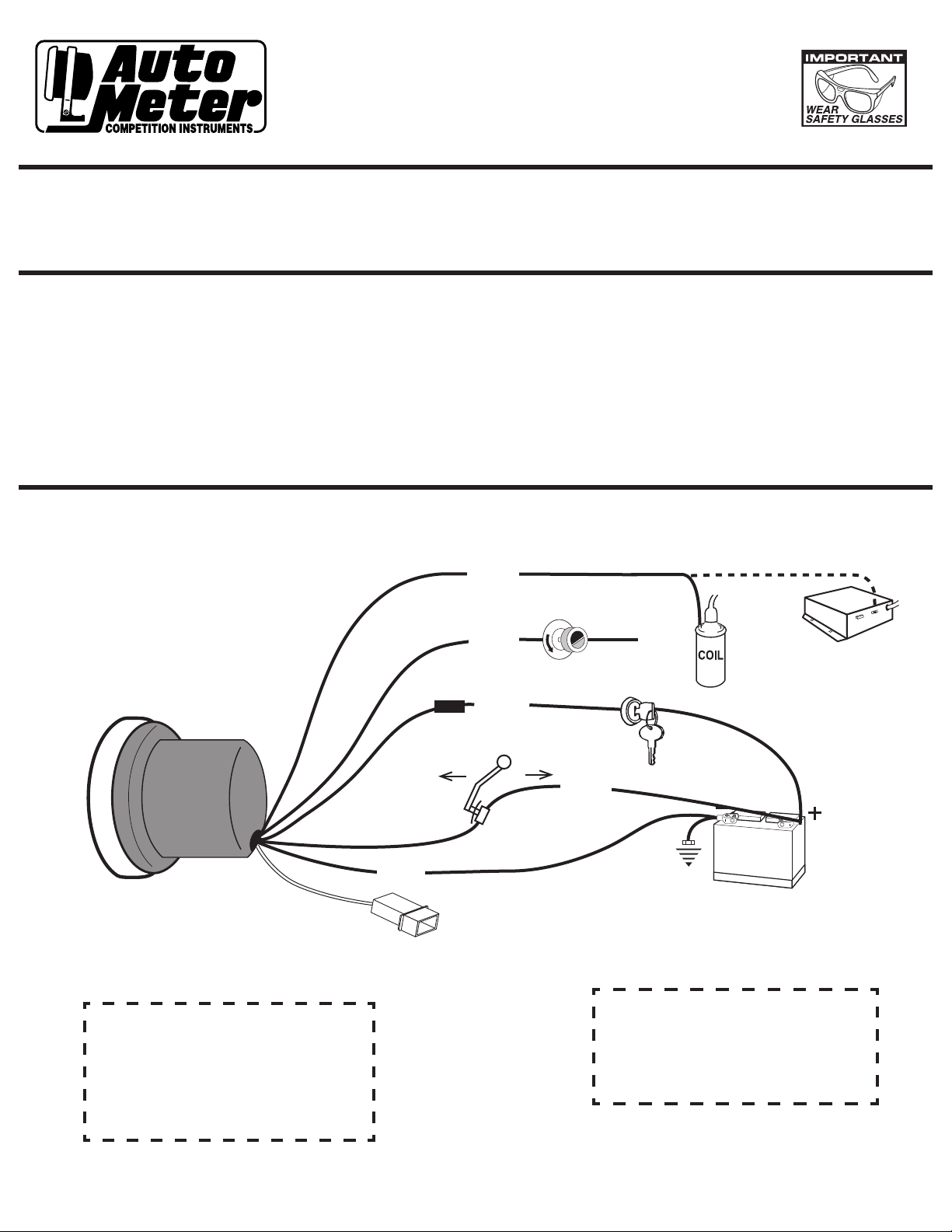
1. WIRING
* See “Warning” below
Tach output on
Electronic ignition
Fuse
(See caution
below)
Switch Closed
when shifter is in
1st or Low
Black
To Shift-Lite
(Optional)
2nd
Green
White
Red
Switch
Customer
Supplied
Momentary
Dash Lighting
1st
Blue
(Only on 2-stage
S.L. Tachs)
Ignition
Good Engine
Ground
or
Switch
12V Battery
As a safety precaution the RED wire of this product should
CAUTION!!!
be fused before connecting it to the positive (+) side of
switched power source. We recommend using a 4 Amp,
3AG fast-acting type cartridge fuse (Littlefuse® #312 004
or an equivalent) inline with the RED wire of our product
for tachs that use a Shift-Lite. For tachs without a ShiftLite we recommend using a 1Amp 3 AG fast-acting type
cartridge fuse (Littlefuse® #312 001 or an equivalent).
*
WARNING
Warranty will be void if connected to coil when using
an aftermarket ignition box such as, but not limited to
products from the following manufacturers: MSD, Crane,
Jacobs, Mallory, Holley, Etc.. Prior to installation of your
tachometer, check with the ignition box manufacturer for
recommended tachometer signal location.
*
See autometer.com/tech_installation.aspx for specic
vehicle information.
Page 2
WARNING
Check with engine builder for maximum
recom mended saf e shift point be fore
setting shift point on tachometer. Failure
to do this could lead to over-revving of
engine, causing serious damage to engine
and car.
IMPORTANT NOTE
This tach has an air core meter movement.
The tach pointer may not always rest at
zero. This is normal. When 12v power
is supplied, pointer will position to the
correct RPM.
Calibration
(Units with
orange &
brown loops)
CLIP NECESSARY
WIRE LOOPS. DO NOT
PUSH WIRES INTO CASE.
8 CYL. — NO adjustment is necessary.
6 CYL. — Clip BROWN wire loop only.
Insulate with electrical tape.
4 CYL. — Clip BROWN and ORANGE
wire loops. Insulate with
electrical tape.
Calibration
CLIP NECESSARY
WIRE LOOPS. DO NOT
PUSH WIRES INTO CASE.
8 CYL. (4 Pulse) — NO adjustment is necessary.
6 CYL. (3 Pulse) — Clip BROWN wire loop only.
Insulate with electrical tape.
4 CYL. (2 Pulse) — Clip BLUE wire loop only.
Insulate with electrical tape.
4 CYL. (1 Pulse) — Clip BROWN and BLUE
wire loops. Insulate with electrical tape.
(Units with blue & brown loops)
* If you are unsure of your
vehicle’s pulse(s) per
revolution or specific
calibration requirements,
contact Auto Meter
Tech Support at (815)
899-0801 or go to http://
hp.autometer.com/
techtips/ techtips.html for
information.
2. CALIBRATION (MODELS WITH NO CALIBRATION LOOPS)
The tachometer is congured at the factory for 4 PPR. To change the PPR on tachs with three buttons, follow the steps below:
1. With no power applied to the tach, press and hold the SET button.
2. Apply power to the tach by turning the ignition key to the “Accessory” or “On” position. Do not start the engine! The pointer will move to a
position on the dial which indicates the default conguration of 4 PPR. Release the SET button.
3. Press and release the (erase) button to increase the PPR setting. Press and release the (recall) button to decrease the PPR setting.
See the tables below to nd the pointer reading that corresponds to the desired PPR for your tachometer type.
4. When the pointer indicates the desired PPR, press and release the SET button to permanently store the settings and exit Conguration mode.
To change the PPR on tachs with two buttons, follow the steps below:
1. With no power applied to the tach, press and hold the yellow RECALL button.
2. Apply power to the tach by turning the ignition key to the “Accessory” or “On” position. Do not start the engine! Release the RECALL button.
The pointer will move to a position on the dial which indicates the default conguration of 4 PPR.
3. Press and release the red ERASE button to change the PPR setting. This will cause the pointer to indicate 5 PPR, then 6 PPR, then down to 0.5 PPR,
then 1, 1.5, 2, 2.5, 3, and back to 4 PPR. See the table below to nd the pointer reading that corresponds to the desired PPR.
4. When the pointer indicates the desired PPR, press and release the yellow RECALL button to permanently
store the settings and exit Conguration mode.
FOR MODELS 6858, 6857, 6856, 3906 AND 6851:
ENGINE Most 2 cyl. Most 4 cyl. Most 6 cyl. Most 8 cyl.
PPR 0.5 1 1.5 2 2.5 3 4 5 6
DIAL RPM 500 1000 1500 2000 2500 3000 4000 5000 6000
FOR MODELS 6809, 6811, 6854, 4499, 6852 and 5795
ENGINE Most 2 cyl. Most 4 cyl. Most 6 cyl. Most 8 cyl.
PPR 0.5 1 1.5 2 2.5 3 4 5 6
DIAL RPM 5000 5500 6000 6500 7000 7500 8000 8500 9000
FOR MODEL 6855:
ENGINE Most 2 cyl. Most 4 cyl. Most 6 cyl. Most 8 cyl.
PPR 0.5 1 1.5 2 2.5 3 4 5 6
DIAL RPM 7000 7500 8000 8500 9000 9500 10000 10500 11000
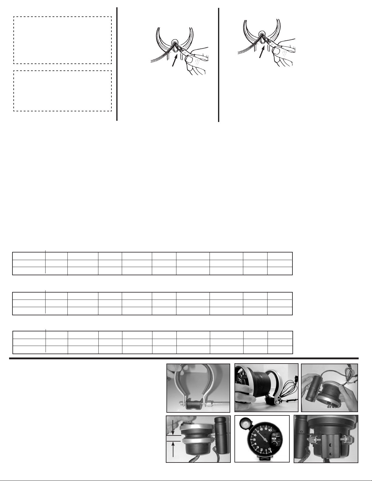
Mounting
1) Loosen both bolts holding the shock strap to the mounting foot. Back both
bolts out until each is only one or two turns into the spacer.
2) Pass tach wires through shock strap assembly and slide tach casing into
shock strap assembly.
3) For external Shift-Lite models, position Shift-Lite mounting bracket under
shock strap as shown in image. Adjust Shift-Lite
(if applicable), tach, and mounting base to desired positions (see figure 4
for recommended shock strap position), and tighten bolts holding mounting
foot to shock strap to secure the assembly.
4) Make sure rubber section of shock strap seats properly to ensure proper
fitment. Check to make sure shock strap is approximately 1
between center line of strap and step of tachometer casing for best
mounting. For external Shift-Lite models, plug shift light into tachometer
connector. Plug is directional, do not force fit!
5) Recommended placement of external Shift-Lite (if applicable) is at 10
o’clock position. It is possible to place Shift-Lite in other positions in
accordance with driver preference and vehicle mounting requirements.
6) The special design of the tachometer base allows for a variety of mounting
possibilities. Attach the base using screws provided or use a pop rivet tool.
(Shift-Lite model shown)
7
⁄8" (1.875”)
1)
2)
17⁄8"
4)
5)
Note: Installation images shown may be different from your actual model.
3)
6)
Page 3

Shift-Point
Erase
Recall
Set
Selection
TM
TACHOMETER
Shift-Lite: For shift-Lite bulb replacement, remove three screws on light.
The bulb, located in the rear section, is easily removed by pushing and
rotating it counter-clockwise. Replace with #1076 automotive bulb.
Display Button: Depressing red button
activates pointer to display Shift-Set RPM
while setting or verifying shift-point.
Note: For model #3903 with internal Shift-Lite, with
key on, engine off, pointer will indicate shift set point.
To adjust turn dial, when pointer indicates desired set
point, stop. Tach will now use set point until changed
Dial light:
For wedge base bulb replacement, order Auto Meter
3219 or GE 86 bulb. Turn socket 1/8 turn counterclockwise to remove. Used on selective models only.
Model
3904
Shown
1. Push and hold red button. Pointer
will display the tachometer’s shiftpoint and the Shift Lite will activate.
2. To set your desired shift-point,
continue depressing the red button,
then push and turn the Shift-Set
knob until the pointer reaches the
desired RPM.
3. To double check, push red set
button-- pointer will indicate your
shift-point.
4. During normal tachometer
operation, the Shift-lite will activate
at the exact same RPM that the
pointer indicates when red set
button is depressed.
Shift-Set: Depress the Shift-Set knob
and turn the knob until the pointe r
indicates the desired shift RPM. This is
exactly where the Shift-Lite will turn on.
Model
3906
Shown
1. Two-Stage Shift-Lite Set Mode (For tachs with two shift-lite set points)
1.1 To enter this mode, apply power to the tach with the engine off (no RPM signal to the tach).
1.2 Press and release the SET button. The pointer moves from 0 RPM to 1K RPM.
This is the indicator for the Low Set shift point.
1.3 Press and release the SET button to review and/or set the Low Set shift point.
` 1.4 Using the “erase” and “recall” buttons, move the pointer to the desired RPM for the Low Set shift point.
1.5 Once the pointer is positioned at the desired RPM, press & release the SET button to store the setting.
1.6 Press and release the “+” button. The pointer moves from 1K RPM to 2K RPM. This is the
indicator for High Set shift point.
1.7 Press and release the SET button to review and/or set the High Set shift point.
1.8 Using the “erase” and “recall” buttons, move the pointer to the desired RPM for the High Set shift point.
1.9 Once the pointer is positioned at the desired RPM, press & release the SET button to store the setting.
NOTE: If the Low Set shift point has been changed, the High Set shift point will also be
changed to the same value.
2. Two-Stage Shift-Lite Application (For tachs with two shift-lite set points)
2.1 To accomplish changing the shift setting, a Blue lead is brought out of the tachometer to a switch that the
driver may manually push. (See diagram in the wiring section.)
2.2 When the switch is closed (pushed), the Blue lead will be connected to 12V Power and the Low Set mode
will be in effect. When the switch is open (released), the High Set mode will be in effect.
2.3 Some racers mount the switch on the transmission or shifter such that when in first gear the switch is
closed, thus placing them in Low Shift set mode. When shifted out of 1st (Low) , the switch returns to open
and places the shift point in the High Set mode.
NOTE: If you prefer to use only one shift point, do not connect the Blue wire as shown in the diagram in
the Wiring section and only set the High Shift Point.
5. Memory Function (For Models with Memory)
3.1 Press “ERASE” button before each race. This clears the memory from your previous run. You are now ready to record.
3.2 Press “RECALL” button to display highest RPM reached. This can be done during or after a race.
Memory is retained even when power to the tachometer is off.
Installation Tips
1. Mount tach base firmly to reduce vibration, wear and tear.
2. Avoid contact of the tach with windshield or other objects to
maintain rubber shock absorbing feature.
3. A 12 V power source MUST be used to power this tachometer.
A 12V motorcycle battery is a good alternative for cars without batteries.
A battery with minimum 5 amp hour rating is recommended.
4. Avoid connecting tach power and ignition power leads together.
Use separate battery leads for ignition and tach to avoid excess voltage drop.
5. Wherever possible, solder wire connections and avoid crimp-type connectors.
This will minimize loose connections that could cause problems later.
6. Make sure you have a good ground to engine and battery negative terminal.
7. Wire installations should be neat and tied down to prevent tugging
and fraying of wires at connections.
For service send your product to Auto Meter in a well packed shipping carton. Please include a note explaining what the problem is along with your phone number. Please specify when you
need the product back. If you need it back immediately mark the outside of the box “RUSH REPAIR,” and Auto Meter will service product within two days after receiving it. ($10.00 charge will be
added to the cost of “RUSH REPAIR.”) If you are sending product back for Warranty adjustment, you must include a copy (or original) of your sales receipt from the place of purchase.
Auto Meter Products, Inc. warrants to the consumer that all Auto Meter High Performance products will be free from defects in material and workmanship for a period of twelve (12) months from date of the
original purchase. Products that fail within this 12 month warranty period will be repaired or replaced at Auto Meter’s option to the consumer, when it is determined by Auto Meter Products, Inc. that the product
failed due to defects in material or workmanship. This warranty is limited to the repair or replacement of parts in the Auto Meter instruments. In no event shall this warranty exceed the original purchase price of
the Auto Meter instruments nor shall Auto Meter Products, Inc. be responsible for special, incidental or consequential damages or costs incurred due to the failure of this product. Warranty claims to Auto Meter
must be transportation prepaid and accompanied with dated proof of purchase. This warranty applies only to the original purchaser of product and is non-transferable. All implied warranties shall be limited in
duration to the said 12 month warranty period. Breaking the instrument seal, improper use or installation, accident, water damage, abuse, unauthorized repairs or alterations voids this warranty. Auto Meter
Products, Inc. disclaims any liability for consequential damages due to breach of any written or implied warranty on all products manufactured by Auto Meter.
12 MONTH LIMITED WARRANTY
FOR SERVICE SEND TO: AUTO METER PRODUCTS, INC. 413 W. Elm St., Sycamore, IL 60178 USA (815) 899-0801
Email us at service@autometer.com
© 2007 Auto Meter Products, Inc.
The Super Bezel is a registered trademark of Auto Meter Products, Inc.
Trouble Shooting
If your tach does not function properly after installation check the following:
1. Are all electrical connections correct and tight?
2. If neither tach nor dial light work, check ground and 12V power connections.
3. Disregard tach readings that occur before engine is started.
4. If problems persist try tach on another vehicle with the same ignition.
5. For changes in ignition type, contact a service representative from Auto Meter.
6. Ignition manufacturers recommend that the ignition and coil be matched according to
criteria which they establish (often that the ignition and coil be products of the same company).
If they are mismatched, minor malfunctions may occur, showing as erratic readings on the tach.
Mismatching coil and ignition types is often the cause of incorrect tach performance.
SERVICE
2650-1244-00 4/17/07
 Loading...