

Page 1
INSTALLATION INSTRUCTIONS
®
BOOST CONTROLLER
2650-1706-00
WARNING!
The installation of the Auto Meter Boost Controller is recommended only for experienced technicians. This product may damage your engine if used properly or
improperly. Use extreme caution during installation and operation. When increasing boost, it is recommended to carefully increase the pressure in small intervals to avoid
engine damage. Auto Meter Products is not responsible for any engine damage caused by improper installation or the use of this product.
The Auto Meter Boost Controller is intended for off-road use only.
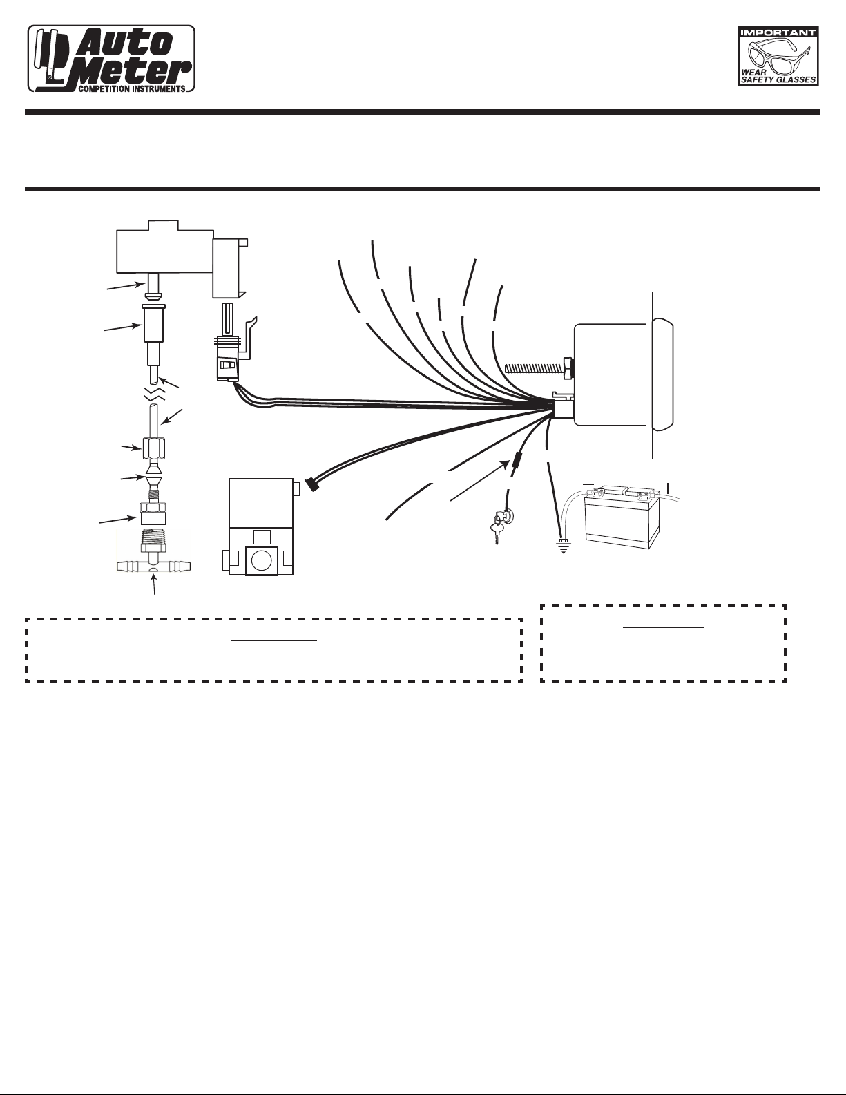
NOTE: MAP Sensor should be mounted with
PRESSURE PORT facing down.
Failure to do so could result in
inaccurate readings due to
condensation in the line.
(Bracket fabrication may be required.)
12V BATTERY
Pressure Port
Tubing Adapter
Compression
Nut
Ferrule
Compression
Adapter
Map Sensor (see note)
Nylon
Tubing
Vacuum “T”
3
2
Boost Control
Valve
Pro Control
1
Pro Control Input
(Optional)
Out
Gray
Orange
+12v
Dash
Lighting
Tach
Signal
Green
Speed
Signal
Violet
White
Fuse
(see
caution
below)
Data Logger
Output
Data Logger and
Pro Control Ground
Blue
Black/White
Red
+12v Connection
*See step 8 below
Black
Good Engine
Ground
CAUTION!
Warranty will be void if connected to coil when using an aftermarket ignition box such as, but not limited to
WARNING!
products from the following manufacturers: MSD, Crane, Jacobs, Mallory, Holley, Etc.. Prior to installation of
your boost controller, check with the ignition box manufacturer for recommended tachometer signal location.
As a safety precaution, the +12V terminal of this
product should be fused before connecting to the
12V ignition switch. We recommend using a 3 AMP
automotive type fuse.
WIRING INSTALLATION
Red Wire (Power):
Connect to a switched +12 volt source.
Black Wire (Ground):
Connect to good engine ground.
White Wire (Lighting Power)
Connect to dash lighting power.
Green Wire (Optional Tach Signal)*
Connect to the negative terminal of a standard ignition coil, or to the "Tach Output" terminal on the electronic ignition module. (See Tach
Signal section for further details)
Violet Wire (Optional Speed Signal)**
Connect to vehicle speed signal. (See Speed Signal section for further details)
Blue Wire (Optional Data Logger Signal Output)***
Connect to signal input(+) or Engine Management System or Data Acquisition unit.
Black/White Wire (Optional*** Data Logger Signal Ground)***
Connect to signal input(-) on Engine Management system or Data Acquisition Unit.
Orange (Optional Pro Control Output)****
Ground trigger for auxiliary device. Maximum 2 amps at 12 volts. (See Pro Control section for further details)
Black/White Wire (Optional Pro Control Ground)****
Connect to a good ground only when Pro Control is used. Pro Control ground reference point. (See Pro Control section for further details)
Gray Wire (Optional Pro Control Ground)****
Grounding this will shut down the Boost Control Valve. This can connect the pro control output to another gauge.
* Only used if Boost by RPM or Boost by Gear is used
** Only used if Boost by Gear is used
*** Only used if vehicle is equipped with a data logger or PCM that can utilize the signal
**** Only used if Pro Control is desired to control an auxiliary electronic device
Page 2
OPERATION
The Auto Meter electric boost controller operates by limiting the boost pressure seen by the wastegate to effectively increase the boost output
by the turbocharger. The Auto Meter boost controller offers configurable warnings, scalable bar graph display, and over boost protection but it is
important to keep watch of your boost levels to keep you and your engine safe. The boost pressure sensor has a maximum pressure capacity
of 30 PSI. Exceeding this pressure can cause damage to the sensor, connections, or most importantly, your engine. Data log output maximizes
at 30 PSI, exceeding this pressure may not be seen on the data log output signal. It is never recommended to increase the boost pressure over
double the wastegate spring pressure.
TACH SIGNAL (REFERENCE PULSES PER REVOLUTION, PAGE 6)
Connect the tach signal to the negative side of the coil* when using a standard ignition. HEI ignition systems will provide a tach signal terminal
off of the distributor cap. If using an electronic ignition module or a factory PCM, a tach signal may be available from the ignition box or PCM.
If the vehicle has multiple ignition coils and no tach output is available from the PCM, the Auto Meter tach adapter part number 9117 is
recommended. Contact Auto Meter if needed for additional information on your application.
*Warranty will be void if connected to coil when using an aftermarket ignition box such as, but not limited to products from the following
manufacturers: MSD, Crane, Jacobs, Mallory, Holley, Etc.. Prior to installation of your tachometer, check with the ignition box manufacturer for
recommended tachometer signal location.
SPEED SIGNAL (REFERENCE TACH AND SPEED SIGNAL TEST, PAGE 6)
If the vehicle has a factory speed sender, you may use the factory signal for the boost controller. This can be accomplished by splicing into the
factory signal from the sender or using a speed output from the PCM or transmission controller.
Any speed sender or electronic module that meets the following two conditions can be used:
1. Pulse rate generated is proportional to vehicle speed.
2. Output voltage within the ranges listed below:
a. Hall effect sender, 3 wire (5 to 16V)
b. Sine wave generator, 2-wire (1.4 VAC min.)
c. Source wave singal from ECM, PCM, TCM 5V to 16V
Recommended – Auto Meter Hall effect sender, 3 wire, 16 pulses/revolution
5291 Standard 7/8" - 18 Thread
5292 Ford, plug in
BOOST SOLENOID INSTALLATION
Install the boost control solenoid using new vacuum lines. Mount the boost solenoid away from any direct heat sources and route all vacuum
lines away from heat or moving parts. If the factory setup includes a restrictive mechanical control or an electric solenoid, they will need to be
bypassed for the boost controller to work as intended. It is recommended that the boost solenoid vent port is routed back into the intake, after
the air flow meter (if equipped) and prior to the turbocharger.
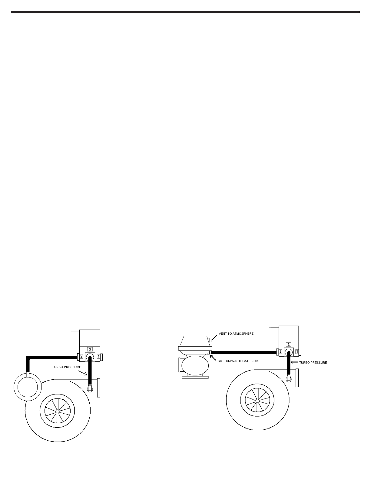
SINGLE TURBO - INTERNAL WASTEGATE SINGLE TURBO - EXTERNAL WASTEGATE, SINGLE PORT
Port 1 – Sintered muffler
Port 2 – To Wastegate
Port 3 – To turbo pressure source
Port 1 – Sintered muffler
Port 2 – To bottom port of wastegate
Port 3 – To turbo pressure source
Page 3
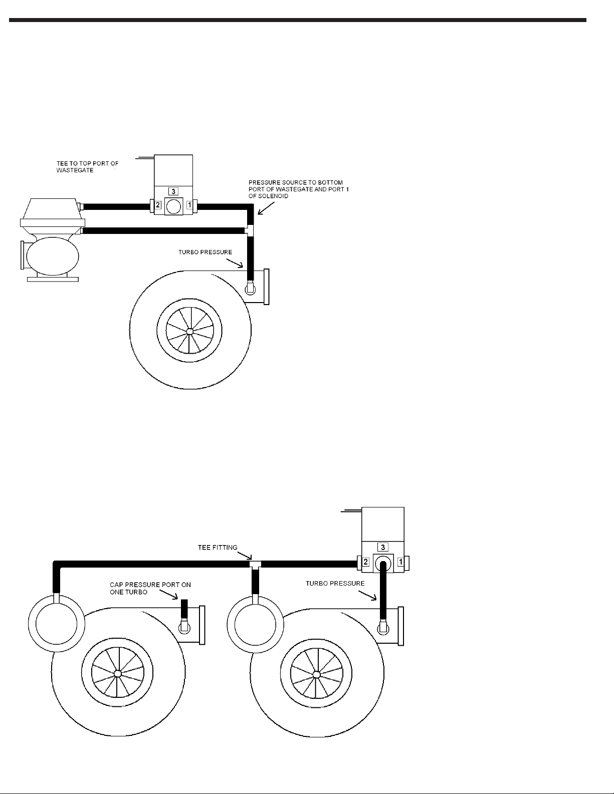
Single Turbo – External Wastegate, Dual Port
This set up is used when higher boost are desired over the previous external
Wastegate single port application
Port 1 – To turbo pressure source, shared with bottom port if the wastegate
Port 2 – To both wastegates
Port 3 – Sintered muffler
TWIN TURBO – INTERNAL WASTEGATES
Port 1 – Sintered muffler
Port 2 – To both wastegates
Port 3 – To turbo pressure source
Page 4

Twin Turbo – External Wastegates, Single Port
Port 1 – Sintered muffler
Port 2 – To bottom port on both wastegates
Port 3 – To turbo pressure source
TWIN TURBO – EXTERNAL WASTEGATES, DUAL PORT
This set up is used when higher boost are desired over the previous external
wastegate single port application
Port 1 – To turbo pressure source, shared with bottom port of both wastegates
Port 2 – To top port on both wastegates
Port 3 – Sintered muffler
Page 5

OPERATION GUIDE
MODE
HI/LO
SELECT
This product has many features that can be adjusted for your specific application. Use the MODE (-), HI/LO, and SELECT (+) buttons to navigate
menu options, confirm selections, and fine tune options to your needs. Pressing Mode will cycle through the top levels of the menu, one step at a
time. Press Select to choose the option.
Key Terms:
A list of acronyms and abbreviations are defined below in order to help you more clearly understand the menu operations, functions, and
components available on your Auto Meter Boost Controller:
BGD – Bar Graph Display. This is the curved, multi-color, LED radial display used to indicate how much vacuum or pressure the MAP sensor
senses.
SSD – Seven Segment Display. This is the digital numeric display that indicates your current pressure reading. This display is also used to help
you navigate and make changes to your settings.
Duty Cycle – The duty cycle is the percentage that the boost solenoid is turned on. This percentage is different for every application. The
percentage is based on the wastegate spring pressure, exhaust pressure, and boost level. We recommend starting with a 20% duty cycle and
increasing the percentage slowly until the desired boost level is reached.
MENU OPTIONS
There are several features provided by your Auto Meter Boost Controller. Use the MODE (-) button to navigate through the following options in
order
• Boost Mode – SSD will display " "
• Peak/Recall – SSD will display " "
• Duty Cycle – SSD will display " "
• Bar Graph Limit/Warning – SSD will display " "
• Pro Control Set Point – SSD will display " "
• Pro Control Active State – SSD will display " "
• Gear Capture – SSD will display " "
• Display Units – SSD will display " "
• Barometric Compensation – SSD will display " "
• Data Logger Output – SSD will display " "
• Pulse Per Revolution – SSD will display " "
• Tacho Signal Test – SSD will display " "
• Speed Signal Test – SSD will display " "
• Firmware Version – SSD will show firmware version
BOOST
CONTROL
MODE
A
U
T
O
M
E
T
E
R
HI/LO
SELECT
1
8
3
4
-
3
1
0
2
©
P
.
C
R
N
O
I
D
S
U
T
C
BOOST MODE SETTING ( )
This allows the user to select one of four basic modes of operation, Press Select. Then press Mode until the desired mode is shown on the
display. NOTE: The boost seleniod will be full on if boost pressure is less than 2 PSI in every mode except .
- Boost control off. In this mode the boost solenoid will be de-energized.
- High/Low mode. The Mac solenoid will be energized at either of two set duty cycles. Pressing the HI/LO button toggles between the high
and low duty cycle settings.
- Boost by RPM. The boost solenoid will be energized at a duty cycle that has been set for each 500 rpm band.
- Boost by gear. The boost solenoid will be energized at a duty cycle that has been set for each gear.
PEAK RECALL ( )
Press the mode button until " " is displayed and then press Select.. The display will show the highest boost pressure measured by the gauge.
To clear this setting, press Hi/LO while the gauge displays the peak pressure. Press the Select button to clear. Press the Mode button to save the
peak reading.
DUTY CYCLE SETTING ( )
This allows the user to set all the applicable duty cycles of the boost control solenoid for the current boost mode. The exact procedure depends
on the current boost mode selected in the Boost ( ) menu. See the respective menu setting procedure below.
If using High/Low Mode ( )
Press the mode button until " " is displayed and then press Select. The display will show LO. To set the low duty cycle value, press Select.
To set the high duty cycle value, press Mode. The display will show HI. Press Select. The current duty cycle value will be shown. Press Select
+ to increase the value, press Mode - to decrease the value. Press HI/LO when the desired value is shown. The display will show . Press
Mode to save the value and exit duty cycle set mode. The new, set value will flash once on the display. If Select is pressed instead of mode,
the new setting will be cancelled. The old value will flash once on the display.
Page 6

If using Boost by RPM mode ( )
Press the mode button until " " is displayed and then press Select. The display will show 0.0. This indicates the lowest rpm band from 0.0 K
RPM to 0.5 K RPM. Press Select. The current duty cycle value for this rpm band will be shown. Press Select + to increase the value, press
Mode - to decrease the value. Press HI/LO when the desired value is shown. The display will show . Press Mode to save the value and exit
duty cycle set mode for this rpm band. The new, set value will flash once on the display. If Select is pressed instead of Mode, the new setting
will be cancelled. The old value will flash once on the display. Press Mode. The display will show 0.5. This indicates the next rpm band from 0.5
K RPM to 1.0 K RPM. Set this and all other rpm bands in the same manner. The highest rpm band set will apply to any higher engine rpm. To
exit set duty cycle mode, press HI/LO when the rpm band is shown.
If using Boost by Gear Mode ( )
Press the mode button until " " is displayed and then press Select. The display will show " ". This indicates the duty cycle setting for first
gear. Press Select to program the duty cycle for 1st gear. The current duty cycle value for this gear will be shown. Press Select + to increase
the value, press Mode - to decrease the value. Press HI/LO when the desired value is shown. The display will show . Press Mode to save
the value and exit duty cycle set mode for this gear. The new, set value will flash once on the display. If Select is pressed instead of Mode, the
new setting will be cancelled. The old value will flash once on the display. On the gear selection screen, press the Mode button to select the
next gear. Follow the same procedure until all of the duty cycle settings have been set for the amount of gears in your transmission. To exit set
duty cycle mode, press HI/LO when a gear number is shown.
BAR GRAPH HIGH LIMIT/WARNING ( )
This sets the boost pressure level that causes the led bar graph to reach its maximum. At this level, all the green leds will be lit. If the boost
level exceeds this set value, the green LED’s will all flash to indicate warning. If boost pressure exceeds this limit by 2.5 psi, the boost mode will
change to off, and the boost solenoid will be de-energized to return to wastegate pressure.
To set the bar graph high limit/warning, press the mode button until " " is displayed and then press Select. The current limit will be shown.
Press Select + to increase the limit, press Mode - to decrease the limit, allowing from 0 PSI to 30 PSI. Press HI/LO when the desired limit is
shown. The display will show . Press Mode to save the limit and exit. The new, set limit will flash once on the display. If Select is pressed
instead of Mode, the new setting will be cancelled. The old limit will flash once on the display.
PRO CONTROL SET POINT ( )
This sets the boost pressure level that causes the Pro Control output to activate. Press the mode button until " " is displayed and then press
Select.. The current value for the Pro Control will be shown. Press Select + to increase the value, press Mode - to decrease the value. Press HI/
LO when the desired value is shown. The display will show . Press Mode to save the value and exit Pro Control value set mode. The new, set
value will flash once on the display. If Select is pressed instead of Mode, the new setting will be cancelled. The old value will flash once on the
display.
PRO CONTROL ACTIVE STATE ( )
This sets whether the Pro Control active state is high or low. Press the mode button until " " is displayed and then press Select. Press Mode
to toggle between and . Press Select to confirm your selection. The display will flash the new setting. Or press HI/LO to exit without
making a change. The display will flash the old setting. If is chosen, the Pro Control output will be switched to ground when the pressure
is less than the Pro Control set value. If is chosen, the Pro Control output will be switched to ground when the pressure exceeds the Pro
Control set value.
GEAR CAPTURE ( )
This is used with the boost by gear mode. A tachometer RPM signal and a speedometer speed signal are both required. Press the mode button
until "gr" is displayed and then press Select.. The display will show . The vehicle must be in first gear and turning the speed sender. Press
Select to save the first gear reading. The display will flash , indicating the gauge has captured the ratio of speed to rpm for the first gear.
Press Mode to move on to the next gear and repeat the process for each gear. You will need to capture each gear for your vehicle and may
capture up to 10 different gears. To exit, press the HI/LO button.
If the Boost Controller does not see a tach signal when trying to capture gears, the display will show "not" for no tach. If the Boost Controller does
not see a speed signal when trying to capture gears, the display will show "noS" for no speed.
PRESSURE UNITS ( )
Press the mode button until " " is displayed and then press Select.. The display will show the current units for pressure. Press mode to
change units. If the display shows PSI, boost pressure is shown in psi, vacuum is shown as in. of Hg. If the display shows " ", boost pressure
is shown in BAR, vacuum in cm. of Hg. If the display shows "KPA", both boost pressure and vacuum are shown in kilopascals. Press Select when
the desired units of measure are displayed
Page 7

BAROMETRIC COMPENSATION ( )
Press the mode button until " " is displayed and then press Select. Press Mode to toggle between On and OFF. Press Select to confirm your
selection. The display will flash the new setting. Or press HI/LO to exit without making a change. The display will flash the old setting. If the OFF
selection is chosen, the pressure shown on the gauge is referenced to standard atmospheric pressure, regardless of altitude. If ON is chosen,
the pressure shown on the gauge is compensated for altitude by a second pressure sensor inside the gauge. At higher altitudes, the displayed
pressure is increased to compensate for atmospheric pressure.
DATA LOGGER OUTPUT ( )
Press the mode button until " " is displayed and then press Select. Press Mode to toggle between and . Press Select to confirm your
selection. The display will flash the new setting. Or press HI/LO to exit without making a change. The display will flash the old setting. If is
chosen, the data logger output will represent the pressure shown on the gauge. To calculate gauge pressure from data logger output voltage:
P = (V * 11.25) - 15
Presssure is referenced in PSI. If pressure is negative, vacuum is referenced as inches of Hg using psi * 2.036.
If PSA is chosen, the data logger output will represent the actual sender output voltage.
To use this feature, you must have a data logger system installed in the vehicle and connect the data logger output from the gauge to the data
logger. Pins number 4 (black/white wire, ground) and 10 (blue wire, signal) in the connector on the back of the gauge are the data logger sensor
signal and ground connections that must be connected to the data logger. After connecting the gauge to the data logger, refer to your data logger
instruction on how to calibrate the data logger to use the signal. The signal provided is a linear 0-4v output from 30inHG (-14.73 PSI) to 30 PSI.
Zero pressure is equal to 1.333v. Pressure above 30 PSI may not be seen on the data logger output signal.
PULSE PER REVOLUTION ( )
This calibrates the tachometer input of the gauge for the number of cylinders. In most cases PPR should be set to half the cylinder number. For
an 8 cylinder engine, PPR should be 4.0. This is important if boost by gear or boost by rpm mode is used. Press the mode button until " " is
displayed and then press Select.. Press Mode to change the PPR value. Press Select when the desired PPR is shown. The display will flash the
new setting. Or press HI/LO to exit without making a change. The display will flash the old setting.
TACH ( ) AND SPEED ( ) SIGNAL TEST
The tach menu allows you to display the engine RPM. Press the mode button until " " is displayed and then press Select. The display
will show the engine rpm, provided the gauge is connected to a proper tach signal source. This can be used to confirm the gauge is properly
connected to a tach signal, and that the pulse per rev. (see PPR) has been set correctly. This is displayed in thousands of rpm. 2,500 rpm would
be displayed as 2.50 on the gauge. Press the Hi/Lo button to exit.
The speed menu allows you to display a speed to confirm that the boost controller has a working signal. Press the mode button until " " is
displayed and then press Select. This will show a speed value, provided the gauge is connected to a proper speedometer signal source. This can
be used to confirm the gauge is properly connected to a speedometer signal. This value is a relative value, not actual MPH. The value should
increase as speed increases, but the numbers will depend on your particular vehicle. Press the Hi/Lo button to exit.
FIRMWARE VERSION
The menu selection after " " is the firmware version number of the gauge.
For service send your product to Auto Meter in a well packed shipping carton. Please include a note explaining what the problem is along with your phone number. Please specify when you
need the product back. If you are sending product back for Warranty adjustment, you must include a copy (or original) of your sales receipt from the place of purchase.
12 MONTH LIMITED WARRANTY
Auto Meter Products, Inc. warrants to the consumer that all Auto Meter High Performance products will be free from defects in material and workmanship for a period of twelve (12) months from date of the original
purchase. Products that fail within this 12 month warranty period will be repaired or replaced at Auto Meter’s option to the consumer, when it is determined by Auto Meter Products, Inc. that the product failed due
to defects in material or workmanship. This warranty is limited to the repair or replacement of parts in the Auto Meter instruments. In no event shall this warranty exceed the original purchase price of the Auto
Meter instruments nor shall Auto Meter Products, Inc. be responsible for special, incidental or consequential damages or costs incurred due to the failure of this product. Warranty claims to Auto Meter must be
transportation prepaid and accompanied with dated proof of purchase. This warranty applies only to the original purchaser of product and is non-transferable. All implied warranties shall be limited in duration to the
said 12 month warranty period. Breaking the instrument seal, improper use or installation, accident, water damage, abuse, unauthorized repairs or alterations voids this warranty. Auto Meter Products, Inc. disclaims
any liability for consequential damages due to breach of any written or implied warranty on all products manufactured by Auto Meter.
SERVICE
FOR SERVICE SEND TO: AUTO METER PRODUCTS, INC. 413 W. Elm St., Sycamore, IL 60178 USA (866) 248-6357
© 2014 Auto Meter Products, Inc.
Email us at service@autometer.com
2650-1706 -00 2/21/14
 Loading...