

Page 1
2650-1143-00
Rev. A
INSTALLATION INSTRUCTIONS
21/16" WIDE BAND AIR/FUEL RATIO MONITOR
®
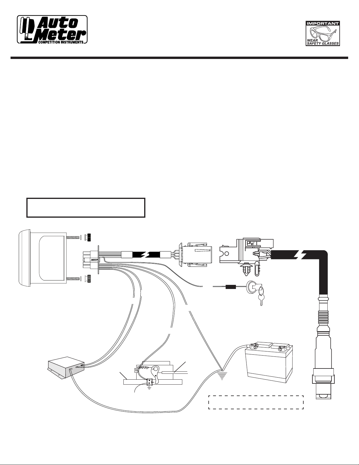
Installation
1. Disconnect the negative (-) battery cable.
2. Gauge can be mounted in a 21⁄16” dia. hole
with brackets supplied. Gauge can also be
mounted in Auto Meter Mounting Cup, or in
Auto Meter Gauge Works Pods.
3. Wire gauge as shown.
WARNING
Sender Will Get Very Hot During Operation.
Red Wire(Power):
Connect to a fused and switched 12V positive source
that is turned on and off with the ignition switch. Place
a 3 amp automotive fuse (available commercially) in
line with this connection to protect your gauge. It is
recommended that vehicles without alternators connect
this wire to a separate switch or direct to the vehicle’s
master cutoff switch. (See Sensor Heating Element Section)
Black Wire(Ground):
Connect to good engine ground.
Brown Wire(Optional Peak/Recall & Warning WOT Switch):
Connect to Wide Open Throttle Switch. Required for
Peak Recall Functionality.
Blue Wire (Optional Data Logger Signal Output):
Connect to signal input(+) or Engine Management System
or Data Acquisition unit.
Blue/Black Wire (Optional Data Logger Signal Ground):
Connect to signal input(-) on Engine Management system
or Data Acquisition Unit.
Data Logger Output
Blue
Blue/Black
Carb or
Throttle Body
Wide Open Throttle Switch
(for WOT peak function)
Black
Brown
Throttle Cable
Red
Fuse
12V Ignition Switch
Good
Engine Ground
Connect Data Acquisition Unit and Air/Fuel
Ratio Monitor to a common grounding point
Page 2

Mounting Sensor
The heated oxygen sensor comes with a stainless steel weld-in bung,
plug, and wiring harness with a weather pack connector. The oxygen
sensor should be installed as close to the cylinder head as is reasonably
possible so that the sensor reaches operating temperature quickly. If
long tube headers are used, the oxygen sensor should be installed in
the collector. If cast iron manifold(s) or shorty headers are used, install
the sensor in the pipe just below the manifold. In multi-bank applications
mounting in the left or right side is acceptable. Turbocharged applications
should have sensor installed 4-5" after turbo on the down pipe.
Auto Meter recommends welding supplied
stainless steel bung with a TIG welder.
1. The exhaust pipe in front of the sensor should not contain any pockets, projections, protrusions, edges, flex-tubes etc. to avoid
accumulation of condensation. A downwards slope of the pipe is recommended. If the exhaust pipe is parallel to the ground, the
sensor must be installed in the top half of the pipe to avoid damage to due to condensation
2. Tightening torque: 30-44 ft Ibs.
3. Avoid excessive heating of the sensor cable. Route sensor cable away from exhaust pipe.
4. The maximum temperature of the sensor on the outside of the exhaust fitting should not exceed 900o F.
The Air / Fuel Ratio Monitor can be used with the following fuels.
Fuels
Unleaded Gasoline
Methanol
Ethanol
LPG (Propane)
CNG
NOTE: OK for use with Nitrous Oxide.
NOTE: Stoichiometric Air / Fuel Ratio is the chemically correct
ratio where theoretically all of the oxygen and all of the
fuel are consumed. The mixture is neither rich or lean.
Stoichiometric Air / Fuel Ratio
14.7:1
15.5:1
17.2:1
6.4:1
9.0:1
Operation Guide
This product has many features that can be adjusted for your specific application. Use the MODE (-) and SELECT (+) buttons to navigate
menu options, confirm selections, and fine tune options to your needs.
Acronyms:
A list of acronyms and abbreviations are defined below in order to help you more clearly understand the menu operations, functions, and
components available on your Auto Meter Wideband Air/Fuel gauge:
BGD – Bar Graph Display. This is the curved, multi-color, LED radial display used to indicate how “Rich” or “Lean” the current Air Fuel or
Lambda reading is relative to your Stoichiometric point with respect to your upper and lower range tolerances.
SSD – Seven Segment Display. This is the digital numeric display that indicates your current Air Fuel or Lambda reading. This display is
also used to help you navigate and make changes to your settings.
AFR – Air / Fuel Ratio. This is shown as a numeric value on the SSD, characterized by only having a single decimal place (i.e. 14.7). This
value is also visually represented on the BGD, indicating whether the value is “Rich” or “Lean” of the selected Stoiciometric value and relative to the upper and lower range tolerances. AFR, as the name implies, represents the ratio of Air to Fuel being mixed and consumed, in
real time, by the engine / vehicle upon which this instrument has been installed.
ʎ Lamda, is an alternate way of expressing AFR, assuming that the stoichiometric point selected equals one and readings “rich” or “lean”
will be expressed as values above or below one, characterized by a value displayed with two decimal places, (i.e. 1.00). The gauge can
display data in either AFR or Lambda as needed by the user.
Real-Time Mode:
Real-Time mode is the default mode of operation for this product. When Real-Time mode is active, the instrument will display the current
air/fuel ratio in either AFR or Lambda.
To toggle between AFR and Lambda display types, press the SELECT(+) button. Remember that AFR values have a single decimal place
(i.e. 14.7), and that Lambda values have two decimal places (i.e. 1.00).
Page 3

Menu Options:
There are several other features provided by your Auto Meter Wideband Air/Fuel Ratio gauge. Use the MODE (-) button to navigate
through the following options in order:
Peak/Recall - SSD will display “P”
Alarm/Warning - SSD will display “ALr”
Stoichiometric AFR Setting - SSD will display “AFr”
BGD Range – SSD will display “dSP”
Auto-Dim – SSD will display “Br”
Heater – SSD will display “Htr”
Once the desired option is displayed on the gauge, press the SELECT(+) button to confirm your selection. Specific Menu options are outlined in the following section.
If no selection is desired, you may continue to press MODE (-) until you return to Real-Time Mode or press neither button for 3 seconds
and the gauge will return to Real-Time Mode on its own.
Wide Open Throttle Peak/Recall Mode:
WOT Peak/Recall mode provides you with a quick and easy way to find out exactly how “Lean” your engine / vehicle got during the last pull,
run, or race. This value is recorded when the Brown Wire in the instrument harness is connected to a good engine ground via a normally
open, momentary closed wide open throttle switch (not included, see wiring diagram) such as may be used with a Nitrous Oxide application.
This allows peak readings to be sampled only during wide open throttle conditions. If the Air / Fuel Monitor gauge will not be used with a Wide
Open Throttle switch, connect the brown wire permanently to a good engine ground to continuously monitor for peak conditions.
To View:
From Real-Time Mode, press MODE (-) to scroll until the display indicates “P”, then press SELECT (+) to display your Peak.
To Clear:
When the Peak value is displayed, press SELECT (+) to clear your Peak value and return to Real-Time Mode. The SSD will display “---
“once the peak has been cleared and until a new peak value has been recorded.
If neither button is pressed for 3 seconds after the Peak Value is displayed, the gauge will return to Real-Time Mode.
Wide Open Throttle Alarm/Warning Mode:
Alarm/Warning mode enables you to program a visual alert point into the gauge in order to warn you of when air/fuel mixtures are running dangerously
lean in your vehicle’s engine. The visual alarm or warning activates when the AFR or Lambda reading reaches or exceeds your programmed alarm
point. When the alarm activates the BGD will blink rapidly to warn the driver of the Alarm condition. Similar to Peak/Recall Mode, this function only
operates when the Brown wire is grounded via a normally open, momentary closed, wide open throttle switch (not included , see wiring diagram) such
as may be wired with a Nitrous Oxide application.
To View your current Alarm Point Setting:
From Real-Time Mode, press MODE (-) to scroll until the display indicates “ALr”, then press SELECT (+) to display your current
Alarm set point.
If neither button is pressed for 3 seconds after the Alarm Point Setting is displayed, the gauge will return to Real-Time Mode.
To Change your Alarm Point Setting:
When the current Alarm set point is displayed, press SELECT (+) to increase your alarm point setting, and MODE (-) to decrease
your alarm point setting.
After you have selected your new alarm set point, the gauge will flash your new set point 5 times on the display and then the SSD
will display “S C” for Save/Cancel.
To confirm your new alarm point setting, press MODE (-). This will save your Alarm set point changes and return
the gauge to Real-Time mode.
To cancel the changes and return to your previous set point, press SELECT (+). This will cancel the Alarm set point changes and
Page 4

Stoichiometric AFR Setting Mode:
The Stoichiometric AFR setting allows you to adjust the gauge scale for alternate fuel types such as Ethanol. As a default this product is set up
for gasoline, with a stoichiometric AFR point of 14.7:1. If you would like to adjust this product for use on an alternate fuel type or would merely
like to adjust the “center” point of your BGD, please follow the instructions below.
To view your current Stoichiometric AFR setting:
From Real-Time Mode, press MODE (-) to scroll until the display indicates “AFr”, then press SELECT (+) to display your current
Stoichiometric set point.
If neither button is pressed for 3 seconds after the Alarm Point Setting is displayed, the gauge will return to Real-Time Mode.
To Change your Stoichiometric AFR setting:
When the current Stoichiometric set point is displayed, press SELECT (+) to increase your Stoichiometric AFR setting, and MODE (-) to
decrease your Stoichiometric AFR setting.
After you have selected your new Stoichiometric set point, the gauge will flash your new set point 5 times on the display and then the
SSD will display “S C” for Save/Cancel.
To confirm your new Stoichiometric setting, press MODE (-). This will save your Stoichiometric set point changes
and return the gauge to Real-Time mode.
To cancel the changes and return to your previous set point, press SELECT (+). This will cancel the Stoichiometric set point changes
and return the gauge to Real-Time mode.
BGD Range Setting Mode:
The Bar Graph Display (BGD) Range Setting Mode allows you to fine tune the resolution of this instrument for your specific application.
With upper and lower set point adjustability, you can set the BGD to utilize the exact range that the engine / vehicle operates within and
see exactly how rich or lean you are running in relation to your current set up and tune. Adjusting your BGD limits also adjusts the scaling
of the 0-4v data logger output supplied from the gauge. The selected low set point of the BGD Range becomes the 0v value of the data
logger output. The selected high set point of the BGD Range becomes the 4v value of the data logger output. Whenever you change these
points, the instrument adjusts the data logger output so that the 0-4v signal is always linear between your chosen set points.
To view your current BGD Range HI / Lean setting or LO / Rich setting:
From Real-Time Mode, press MODE (-) to scroll until the display indicates “dSP”, then press SELECT (+) to display your current
BGD Range set point.
The SSD of your display will show “HI” in the display to indicate that you will be viewing the “above Stoichiometric” or
“Lean”upper range boundary.
If you would like to view the LO / Rich setting, press MODE (-) when “HI” is shown on the SSD. The SSD should
now indicate “LO”.
When the desired setting, “HI” or “LO”, is displayed, confirm this selection by pressing SELECT (+). The upper or lower BGD range
value will then be displayed in the SSD of your gauge corresponding to your selection.
Note: When your selection is made and the numeric range value is shown, LEDs in the BGD will light to indicate which set point
you are viewing. If the LEDs to the left of center or Stoichiometric are lit, you are viewing the “LO” or Rich set point. If the LEDs
to the right of center or Stoichiometric are lit, you are viewing the “HI” or Lean set point.
If neither button is pressed for 3 seconds after the BGD Range “HI” Setting is displayed, the gauge will return to Real-Time Mode.
To Change your BGD Range setting:
When the current BGD Range “HI” or “LO” set point is displayed, press SELECT (+) to increase your chosen BGD Range setting,
and MODE (-) to decrease your BGD Range setting.
After you have selected your new BGD Range set point, the gauge will flash your new set point 5 times on the display and then the
SSD will display “S C” for Save/Cancel.
To confirm your new BGD Range setting, press MODE (-). This will save your BGD Range set point changes
and return the gauge to Real-Time mode.
To cancel the changes and return to your previous set point, press SELECT (+). This will cancel the BGD Range set point changes
and return the gauge to Real-Time mode.
Page 5

Auto-Dim Mode:
This product incorporates an Auto-Dimming feature that allows it to adjust automatically for varying lighting conditions. This is accomplished
with a sensor light embedded in the dial. You may enable or disable this feature depending upon your viewing preference. When Auto-Dim
mode is disabled, the product and LED’s operate at maximum brightness regardless of atmospheric lighting conditions. The auto-dim mode
is set to “off” from the factory.
To view your current Auto-Dim setting:
From Real-Time Mode, press MODE (-) to scroll until the display indicates “Br” for brightness, then press SELECT (+) to display your
current Auto-Dim setting which will be indicated as either “ON” or “OFF” in the SSD.
If neither button is pressed for 3 seconds after the Auto-Dim Setting is displayed, the gauge will return to Real-Time Mode.
To Change your Auto-Dim setting:
When the current Auto-Dim setting is displayed, press MODE (-) to toggle between “On” and “OFF”.
After you have selected your new Auto-Dim setting, the gauge will flash your new setting 5 times on the display and then the SSD
will display “S C” for Save/Cancel.
To confirm your new Auto-Dim setting, press MODE (-). This will save your Auto-Dim setting changes and return
the gauge to Real-Time mode.
To cancel the changes and return to your previous set point, press SELECT (+). This will cancel the Auto-Dim setting changes and
return the gauge to Real-Time mode.
Heater Control Mode:
All O2 sensors must be heated before an accurate signal is produced. Potential sensor damage can occur if the gauge begins to heat the
sensor before the engine is running due to condensation that forms on the sensor tip and in the exhaust. To accommodate this, an internal
trigger within the gauge will automatically begin heating the sensor when 13.5 volts or higher is seen on the Red wire (“Normal” operating
mode). While the gauge does not require 13.5 volts to operate (12 volts will suffice), this voltage is used to indicate to the gauge that the
engine is running, as most regulated charging systems will maintain 14 volts or higher. Once the gauge sees 13.5 volts, it will begin
heating the sensor and transition from (---) to a 20 second countdown on the seven-segment display. When the countdown is complete,
the sensor is heated, and the gauge will begin reading air/fuel ratio in real-time.
In applications where a standard charging system is not used (vehicles without a regulated alternator, for example) there is an override
available that will allow sensor heating to occur without the gauge reading a 13.5 volt trigger. This can be accomplished while the sevensegment display shows (---) (thereby overriding “Normal” operating mode) or set to trigger when 12 volts is applied on the Red wire
(“On” operating mode).
To View your current Heater Operating Mode:
From Real-Time Mode, press MODE (-) to scroll until the display indicates “Htr”, then press SELECT (+) to display your current
Heater Operating Mode.
If neither button is pressed for 3 seconds after the Heater Operating Mode is displayed, the gauge will return to Real-Time Mode.
To Override “Normal” Operating Mode:
While displaying (---), press any button to begin the 20-second heater process.
To Switch Between Heater Operating Modes:
When the current heater operating mode is displayed (either “Nor” or “On”), press SELECT (+) to choose the current setting or
MODE (-) to switch to the alternate setting.
After you have selected your new Heater Operating Mode, the SSD will display “S C” for Save/Cancel.
To confirm your new Heater Operating Mode, press MODE (-). This will save your current Heater Operating Mode and return the
gauge to Real-Time mode.
To cancel the changes and return to your previous Heater Operating Mode, press SELECT (+). This will cancel the Heater
Operating Mode change and return the gauge to Real-Time mode.
Page 6

Red
Green
Amber
MODE SELECT
-
+
Data Logger Output Range:
The Auto Meter Wideband Air / Fuel gauge has a signal output for supplying information to a Data Logger or engine management system. The signal
provided is a linear 0-4v output. See the BGD Range Setting Mode for information about how to define the air/fuel mixture values for low (0v) and high
(4v) ranges of the output in order to scale this linear signal output for best operation with your Data Logger or engine management.
Warning
Fouling and/or permanent damage to the oxygen sensor
over time will result if used with any of the following:
• Leaded gasoline and fuel additives containing lead
• 2 cycle gasoline (gas/oil mix)
• Diesel Fuel
• Nitromethane
• Excessively rich mixtures
If the Air/Fuel Ratio Monitor responds sluggish, the oxygen
sensor is probably partially fouled and should be replaced.
LED Chart
Lean Range Eight red LED’s
Stoichiometric Range Fourteen green LED’s
Rich Range Eight amber LED’s
For service send your product to Auto Meter in a well packed shipping carton. Please include a note explaining what the problem is along with your phone number. Please specify
when you need the product back. If you need it back immediately mark the outside of the box “RUSH REPAIR,” and Auto Meter will service product within two days after receiving
it. ($10.00 charge will be added to the cost of “RUSH REPAIR.”) If you are sending product back for warranty adjustment, you must include a copy (or original) of your sales
Auto Meter Products, Inc. warrants to the consumer that this product will be free from defects in material and workmanship for a period of twelve (12) months from date of the original purchase. Products that
fall within this 12 month warranty period will be repaired or replaced at Auto Meter’s option to the consumer, when it is determined by Auto Meter Products, Inc. that the product failed due to defects in material
or workmanship. This warranty is limited to the repair or replacement of parts in the Auto Meter instruments. In no event shall this warranty exceed the original purchase price of the Auto Meter instruments nor
shall Auto Meter Products, Inc. be responsible for special, incidental or consequential damages or costs incurred due to the failure of this product. Warranty claims to Auto Meter must be transpotation prepaid
and accompanied with dated proof of purchase. This warranty applies only to the original purchaser of product and is non-transferable. All implied warranties shall be limited in duration to the said 12 month
warranty period. Breaking the instrument seal, improper use or installation, accident, water damage, abuse, unauthorized repairs or alterations voids this warranty. Auto Meter Products, Inc. disclaims any liability
for consequential damages due to breach of any written or implied warranty on all products manufactured by Auto Meter.
receipt from the place of purchase.
12 MONTH LIMITED WARRANTY
SERVICE
FOR SERVICE SEND TO: AUTO METER PRODUCTS, INC. 413 W. Elm St., Sycamore, IL 60178 (815) 899-0801
The “Super Bezel” is a registered trademark of Auto Meter Products, Inc.
For Email: Service@autometer.com
© 2007 Auto Meter Products. Inc. 2650-1143-00 Rev. A 10/27/06
 Loading...