

Page 1
INSTALLATION INSTRUCTIONS
IMPORTANT
1-1/2" ELECTRIC MINI GAUGES
Instr. No. 2650-235D
Congratulations! You have purchased a quality
gauge that will help you monitor your vehicle's vital
functions. 18-gage wire is required for installation
and can be purchased separately at an auto parts
store near you. Auto Meter wire kit no. 2214 is
recommended.
Preliminary Steps
1. Read instructions thoroughly. Please consult a qualified mechanic if
you have not had training in the proper installation of instruments.
2. Determine ideal mounting location. Choose a location that will not
obstruct visibility or impair driving. Consult your vehicle's repair manual
to locate:
A) water temperature port
B) 12V ignition switch or fuse box
C) oil pressure port
3. Consult your vehicle's manual to determine the best route for tubing to
follow. Choose a path free from hazard of moving parts or hot engine
components.
4. Assemble tools and parts required for installation.
5. Disconnect negative (-) battery cable. Do not allow terminal to touch
battery or any metal. (NOTE: Disconnecting battery ground may require
you to re-program your radio station and clock after re-connection.
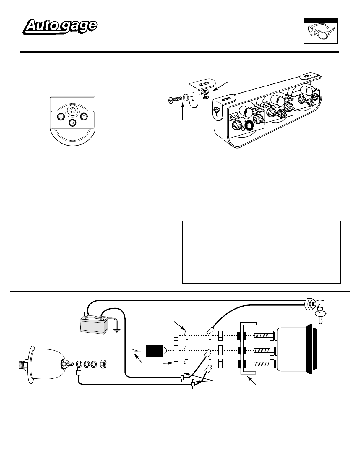
6. Hold console in desired mounting location and use as a template to
mark drill holes on underside of dash.
7. Drill holes with an 1/8" drill bit and mount bracket under dash using
self-tapping screws and flat washers provided. Mount console to
bracket by lining up side holes of bracket with side holes in console. Fit
8-32x1/2" screws and no. 8 flat washers provided through side holes in
bracket and console. Screw into nut attached to inside of panel.
MODEL 2354, 2355, 2356, 2391
Models 2354,
2355, 2356
No. 8 Screw & Flat
Washer Use No. 8
Nut on inside panel.
WEAR
SAFETY GLASSES
Model 2391
Self-Tapping Screw with Washer
(Used to attach bracket before
mounting panel)
CAUTION: Some late model vehicles use electronic sensors in their
pressure and temperature senders for engine control functions. Before
removing the original senders, we recommend that you contact your
automotive dealer to be sure no critical functions will be disrupted.
■ With pressure gauges, it is beneficial to add a T-fitting to install your
new gauge and to keep the warning light operational. This allows you
to monitor the pressure and still have a warning light to indicate
emergency conditions.
NOTE: For light bulb replacement order Auto gage no. 2388.
Important Assembly Procedures To Follow
Tighten nuts and lock washer that secure the gauge mounting bracket.
Be sure they are not so tight as to bend or distort mounting bracket.
Install additional wiring and hardware as shown in diagrams below.
Now tighten the outer nut while holding the inner nut. This is the only
correct procedure and must be followed to insure safe electrical
connections. This applies to the gauge and both senders.
Make sure wires are not rubbing against metal or each other.
Oil Pressure
To Oil
Pressure
Port On
Engine
Pressure Sender
1. Drill a 3/8" dia. hole in firewall. Install rubber grommet provided in
firewall to insulate wire where it passes through sheet metal.
2. Remove existing oil pressure sender. (For computerized vehicles see
caution in Preliminary Steps.) Install new Pressure Sender using
sealing compound on pipe threads.
3. Cut three lengths of 18-gage wire. Strip insulation back 1/4" on each
end of wire and attach solder lug terminals to each end.
4. Connect one end of wire with solder lug terminal to sender (S) terminal
post on back of gauge using split lockwasher and nut provided. Route
wire through firewall. Connect opposite end of wire with solder lug
terminal to pressure sender using split lockwasher and nut provided.
GROUND
Split Lockwasher
Connect lights
to dash lighting
curcuit (12V).
To Good
Engine
GROUND
Nut
(+)
(-)
(S)
Grommet
Placed In
Firewall
5. Connect one end of wire with solder lug terminal to negative (-)
terminal post on back of gauge using split lockwasher and nut
provided. Connect opposite end to good engine ground, such as body
frame bolt.
6. Connect solder lug terminal and wire to positive (+) terminal post on
back of gauge using split lockwasher and nut provided. Connect
opposite end of wire to accessory terminal on fuse block with solder
lug terminal to ignition switch.
CAUTION: Be careful not to touch ignition wire to negative (-) terminal
on back of gauge or sender will be damaged.
to complete installation.
Steel Mounting Bracket
with Plastic Insulators.
See final procedures
Ignition Switch
Terminal
Or Other 12V
Source that is
turned off
when ign. is
off.
Page 2
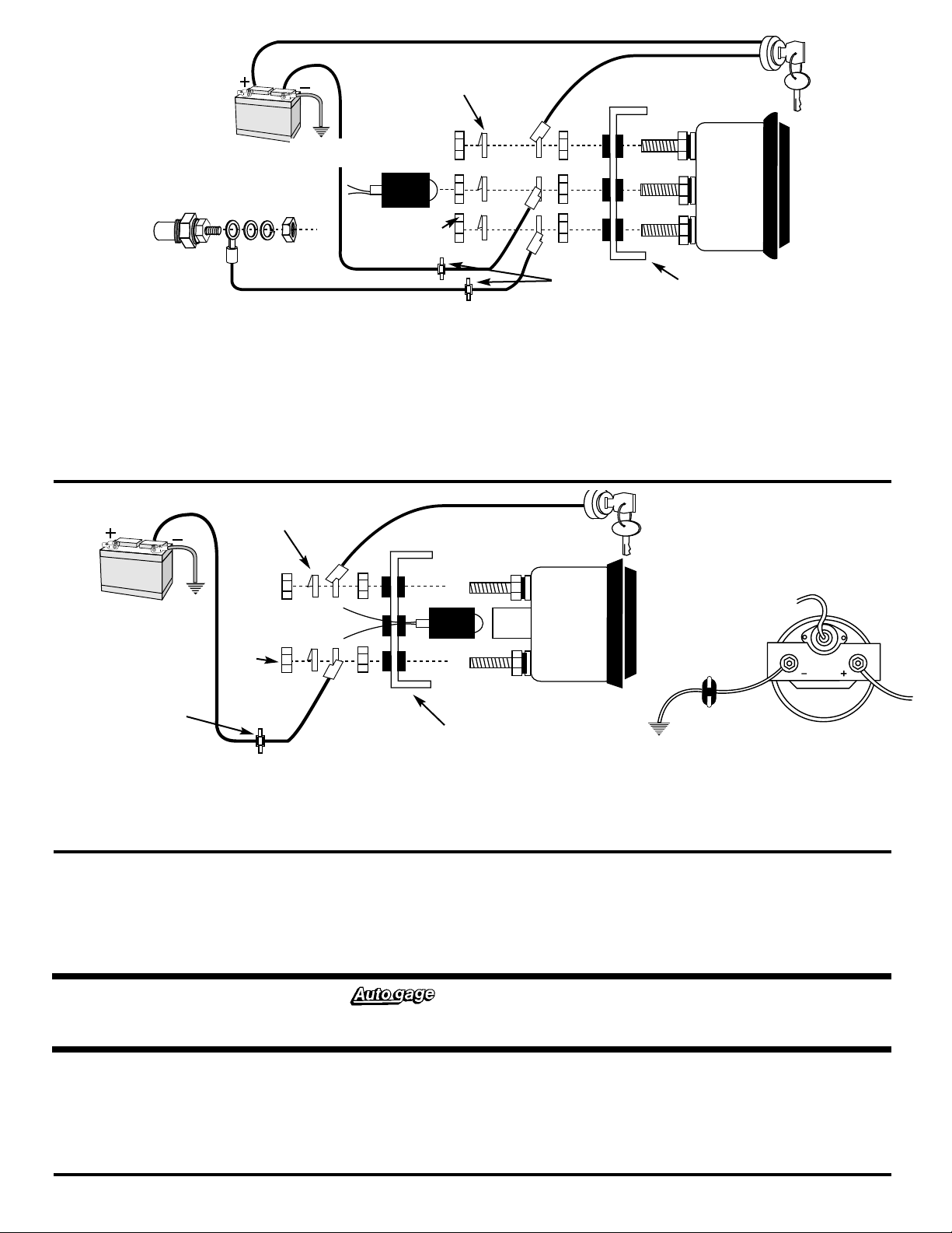
Water Temperature
12V BATTERY
(+)
(-)
(S)
12V BATTERY
(+)
(-)
Split Lockwasher
Connect lights
GROUND
To Coolant
Temperature
Port On Engine
Temperature
Sender
NOTE: Use Teflon
Sealing Tape or Sealing
Compound on threads.
1. Drill a 3/8" dia. hole in firewall. Install rubber grommet provided in
firewall to insulate wire where it passes through sheet metal.
2. Drain antifreeze from cooled radiator into a container.
coolant!
Save antifreeze to refill radiator after installation. Remove
existing water temperature sender for indicator light and install new
sender. (For computerized vehicles see caution in Preliminary Steps.) If
indicator light is still desired, a second port must be drilled and tapped in
block.
3. Cut three lengths of 18-gage wire. Strip insulation back 1/4" on each
end of wire and attach solder lug terminals to each end.
4. Connect one end of wire with solder lug terminal to negative (-)
terminal post on back of gauge using split lockwasher and nut
to dash lighting
curcuit (12V).
To Good
Engine
GROUND
Never drain hot
Nut
Ignition Switch
Terminal Or
Other 12V
Source that is
turned off when
ign. is off.
Grommet Placed
In Firewall
provided. Connect opposite end of wire with solder lug terminal to
good engine ground, such as body frame bolt.
5. Connect one end of wire with solder lug terminal to positive (+)
terminal post on back of gauge using split lockwasher and nut
provided. Connect opposite end of wire with solder lug terminal to
ignition switch or accessory terminal on fuse block.
CAUTION: Be careful not to touch ignition wire to negative (-) terminal
on back of gauge or sender will be damaged.
Steel Mounting Bracket
with Plastic Insulators.
See final procedures to complete installation.
NOTE: 18-gage wire is required for installation of this consle. Auto
Meter wire kit no. 2214 is recommended and may be purchased
separately at an auto parts store near you.
Voltmeter
GROUND
Grommet
Placed In
Firewall
1. Drill a 3/8" dia. hole in firewall. Install rubber grommet provided in
firewall to insulate wire where it passes through sheet metal.
2. Cut two lengths of 18-gage wire. Strip insulation back 1/4" on each
end of wire and attach solder lug terminals to each end.
3. Connect one end of wire with solder lug terminal to negative (-)
terminal position on back of gauge using split lockwasher and nut
Split Lockwasher
To dash lighting (12V).
GROUND
Nut
Final Procedures
1. Insert light bulb and socket assembly into back of gauge. Connect red
lighting wire to 12V power source in dash lighting circuit. Connect
black wires to good engine ground, such as body frame bolt.
2. Reconnect negative (-) battery cable. Re-program your clock and
radio if necessary.
Ignition Switch Terminal
Or Other 12V Source that is turned off
when ign. is off.
To Good
Engine
GROUND
Steel Mounting Bracket
with Plastic Insulators.
provided. Connect opposite end of wire to good engine ground, such
as body frame bolt.
4. Connect one end of wire with solder lug terminal to positive (+)
terminal on back of gauge using split lockwasher and nut provided.
Connect opposite end to 12V terminal on ignition switch or any 12V
source.
See final procedures to complete installation.
3. Wrap a clean rag around fittings on back of oil pressure gauge and
place a pan on floor under them to protect vehicle interior from
potential leaking oil. Start engine and run for 30 seconds. Shut engine
off and check rag for leaks. If none appear, start engine again and
visually check all connections for leaks.
Grommet
BACK VIEW
Service
For service send your gauge to Auto Meter in a well packed shipping carton. Please include a note explaining what the problem is, the year and model of your vehicle, engine size,
etc., and your phone number. If you are sending a gauge back for Warranty adjustment, you must include a copy (or original) o f your sales receipt from the place of purchase.
12 MONTH LIMITED WARRANTY
The manufacturer warrants to the consumer that this product will be free from defects in materials and workmanship for a period of twelve (12) months from the date of the original purchase.
Products that fail within this 12 month warranty period will be repaired or replaced at the manufacturer's option to the consumer, when determined by the manufacturer that the product failed
because of defects in material or workmanship. This warranty is limited to the repair or replacement of parts in the instrument and the necessary labor done by the manufacturer to affect the
repair or replacement of the instrument. In no event shall this warranty exceed the original purchase price of the instrument, nor shall the manufacturer be responsible for special, incidental
or consequential damages or costs incurred due to failure of this product. Warranty claims to the manufacturer must be transportation prepaid and accompanied with dated proof of purchase.
This warranty applies only to the original purchaser of product and is non-transferable. All implied warranties shall be limited in duration to the said 12 month warranty period. Breaking the
meter seal, improper use or installation, accident, water damage, abuse, unauthorized repairs or alterations voids this warranty. The manufacturer disclaims any liability for consequential
damages due to breach of any written or implied warranty on all products made by the manufacturer.
FOR SERVICE SEND TO: AUTO METER PRODUCTS, INC. 413 W. Elm St., Sycamore, IL 60178 (815) 895-8141
© 2001 Auto Meter Products, Inc.
2/20/01 2650-235D
 Loading...