

Page 1
®
IMPORTANT
WEAR
SAFETY GLASSES
by
INSTALLATION
INSTRUCTIONS
Instr. No. 2650-317B
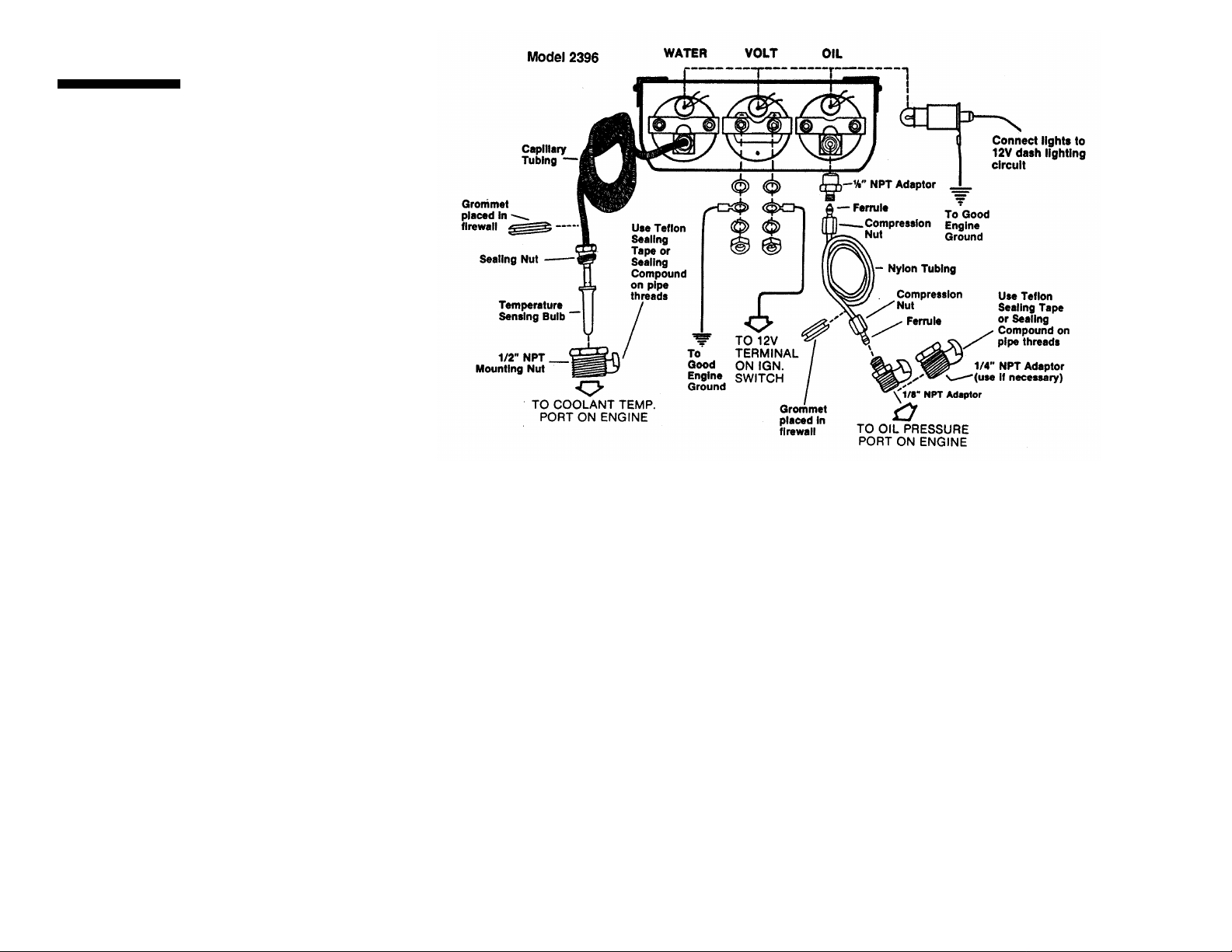
1-1/2" Mechanical Mini Gauges
MODEL 2351, 2352 & 2396
WARNING: Some late model vehicles use electronic sensors in
their pressure and temperature senders for engine control
functions. Before removing the original senders, we recommend
that you contact your automotive dealer to be sure no critical
functions will be disrupted. With pressure gauges, it is beneficial
to add a T-fitting to install your new gauge and to keep the
warning light operational. This allows you to monitor the pressure
and still have a warning light to indicate emergency conditions.
Preliminary Steps
1. Read instructions thoroughly. Please consult a qualified mechanic if you have
not had training on the proper installation of instruments.
2. Consult your vehicle's repair manual to locate:
A) oil pressure port,
B) 12V ignition switch or fuse box , and
C) water temperature port
3. Determine ideal mounting location. Choose a location that will not obstruct
visibility or impair driving movement.
4. Determine the best route for tubing to follow. Choose a path free of hazards
of moving parts or hot engine components.
5. Assemble tools and parts required for installation.
6. Remove gauges from metal panel. Notice their placement to make
reassembly easier.
7. Disconnect negative (-) battery cable.
8. Hold panel in desired mounting location. Use panel as template and mark
holes to be drilled for mounting. ( For mini consoles, use mounting brackets
as templates.)
9. Drill holes with a 9/64" drill bit and attach metal panel with self-tapping
screws provided.
For actual gauge installation, see further instructions inside.
Oil Pressure, cont.
4. Route tubing through small grommet in firewall and cut to
meet mounted panel (leave one foot of extra length before
cutting). Be sure to avoid potential hazard of moving parts
or hot engine components.
5. Secure gauge in mounted panel using non-insulated
mounting bracket.
6. Slide sealing nut and ferrule on this end of tubing and
tighten in the same manner described in Step 4 (use 9/16"
and 3/8" open-ended wrenches).
Final Procedures
(Follow these steps after you've completed the steps for all three gaugeslisted on inside pages.)
1. Insert light bulb and socket assembly into back of each gauge. Connect all red
lighting wires to 12V power source in dash lighting circuit. This allows the gauge
lights to be dimmed with normal dash lighting and only used at night. Connect the
black wires to good engine ground. (Body frame bolt is a good engine ground.)
2. Reconnect negative (-) battery cable.
3. Wrap a clean rag around fittings on back of oil pressure gauge and place a pan
on floor under them to protect vehicle interior from potential oil leaking. Start
engine and run for 30 seconds. Shut engine off and check rag for leaks. If none
appear, start engine again and visually check all connections for leaks.
®
SERVICE
For service send your gauge to Auto Meter in a well packed shipping carton. Please include a
note explaining what the problem is, the year and model of your vehicle, engine size, etc., and
your phone number. If you are sending a gauge back for Warranty adjustment, you must
include a copy (or original) of your sales receipt from the place of purchase.
Auto Meter Products, Inc. warrants to the consumer that all Auto gage instruments will be free from defects in materials
and workmanship for a period of twelve (12) months from the date of the original purchase. Products that fail within this 12
month warranty period will be repaired or replaced at Auto Meter's option to the consumer, when determined by Auto
Meter Products, Inc. that the product failed because of defects in material or workmanship. This warranty is limited to the
repair or replacement of parts in the Auto gage instrument and the necessary labor done by Auto Meter Products, Inc. to
affect the repair or replacement of the Auto gage instrument. In no event shall this warranty exceed the original purchase
price of the Auto gage instrument, nor shall Auto Meter Products, Inc. be responsible for special, incidental or
consequential damages or costs incurred due to failure of this product. Warranty claims to Auto Meter Products, Inc. must
be transportation prepaid and accompanied with dated proof of purchase. This warranty applies only to the original
purchaser of product and is non-transferable. All implied warranties shall be limited in duration to the said 12 month
warranty period. Breaking the meter seal, improper use or installation, accident, water damage, abuse, unauthorized
repairs or alterations voids this warranty. Auto Meter Products, Inc. disclaims any liability for consequential damages due
to breach of any written or implied warranty on all products made by Auto Meter.
FOR SERVICESEND TO: AUTO METER PRODUCTS, INC.
12 MONTH LIMITED WARRANTY
413 W. Elm St.,
Sycamore, IL 60178
(815) 895-8141
Page 2
Tools Required
Electric Drill
Drill Bits: 9/64", 3/8", 7/8" dias.
Open-End Wrenches: 7/16", 9/16", 3/8", 7/8"
Standard Screwdriver
Clean Rag
Thread Sealing Compound
NOTE: For Model 2351 & 2352 single gauges, refer
to hook-up instructions for your particular gauge.
Water Temperature
1. Drain coolant from cooled radiator into a container.
hot coolant!
2. Drill a 7/8" dia. hole in firewall and route temperature sensing
bulb through mounted panel first and then through firewall
hole. Slit rubber grommet and position in firewall hole to hold
gauge tubing in place.
3. Using sealing compound on threads, insert and tighten
mounting nut in the 1/2" NPT port in engine. (Use 7/8" openend wrench). If port opening is not 1/2" NPT, use the 3/8"
adapter provided in kit. Insert temperature sensing bulb into
mounting nut and carefully thread the sealing nut into the
mounting nut. Be sure to hold the mounting nut securely
(with 7/8" open-end wrench) while tightening sealing nut
(with 5/8" open-end wrench). Check that tubing is free from
hazard of moving parts or hot engine components.
4. Refill radiator with coolant.
5. Secure gauge in mounted panel using non-insulated
mounting bracket.
Note: Whenever removing temp. sensing bulb, loosed sealing
nut but DO NOT allow mounting nut to rotate. Rotation may
break capillary tubing, thus voiding warranty.
Save antifreeze to refill radiator after installation.
Never drain
Voltmeter
1. Negative (-) battery cable should remain disconnected.
2. Fasten voltmeter in metal panel using insulated bracket, 2
lockwashers, and 2 #10 nuts.
3. Cut two lengths of 18-gauge wire. One wire is for connecting
gauge to fuse box, the other connects to good engine
ground. Strip insulation back 1/4" on one end of each wire.
Attach solder lug terminal and wire to positive (+) terminal on
back of gauge using proper lockwashers and #10 nut.
Connect other end of this wire to appropriate 12V source at
fuse box. Attach the ground wire to negative (-) terminal on
back of gauge and connect other end to good engine ground.
(Body frame bolt is a good engine ground.)
Oil Pressure
1. Drill a 3/8" dia. hole in firewall. Install small rubber grommet in
firewall to insulate nylon tubing where it passes through
sheet metal.
2. Remove existing oil pressure sender (for computerized
vehicles, see warning on pg. 1). Install 1/8" NPT adapter
(with 7/16" open-end wrench) in this location using sealing
compound on pipe threads. If 1/4" NPT adapter is needed,
install it first instead ( with 9/16" open-end wrench). Be sure
to hold 1/4" NPT adapter while tightening 1/8" NPT adapter
firm (with 7/16" open-end wrench).
3. To help prevent leaks, be sure the end of nylon tubing is cut
cleanly and straight. Slide compression nut onto tubing with
threads toward end of tubing. Slide ferrule onto end of tubing,
leaving 3/16" between ferrule and end of tube. Insert end of
tubing into 1/8" NPT adapter. Apply pressure to maintain
constant bond between end of tubing and inside of adapter.
Slide ferrule into the adapter then compression nut. Tighten
compression nut (with 3/8" open-end wrench) while holding
1/8" NPT adapter firm (with 7/16" open-end wrench). To
make sure it is a snug fit, tug lightly on nylon tubing to make
sure it doesn't come out.
(Steps for installing this gauge continue on back cover.)
 Loading...