

Page 1
GND
S I
INSTALLATION INSTRUCTIONS
GND
S I
21/16" ELECTRIC GAUGES
2650-1179
If after completely reading these instructions you have questions regarding the operation or installation of your instrument(s),
please contact Auto Meter Technical Service at 815-899-0801. You may also email us at service@autometer.com.
Additional information can also be found at http://www.autometer.com
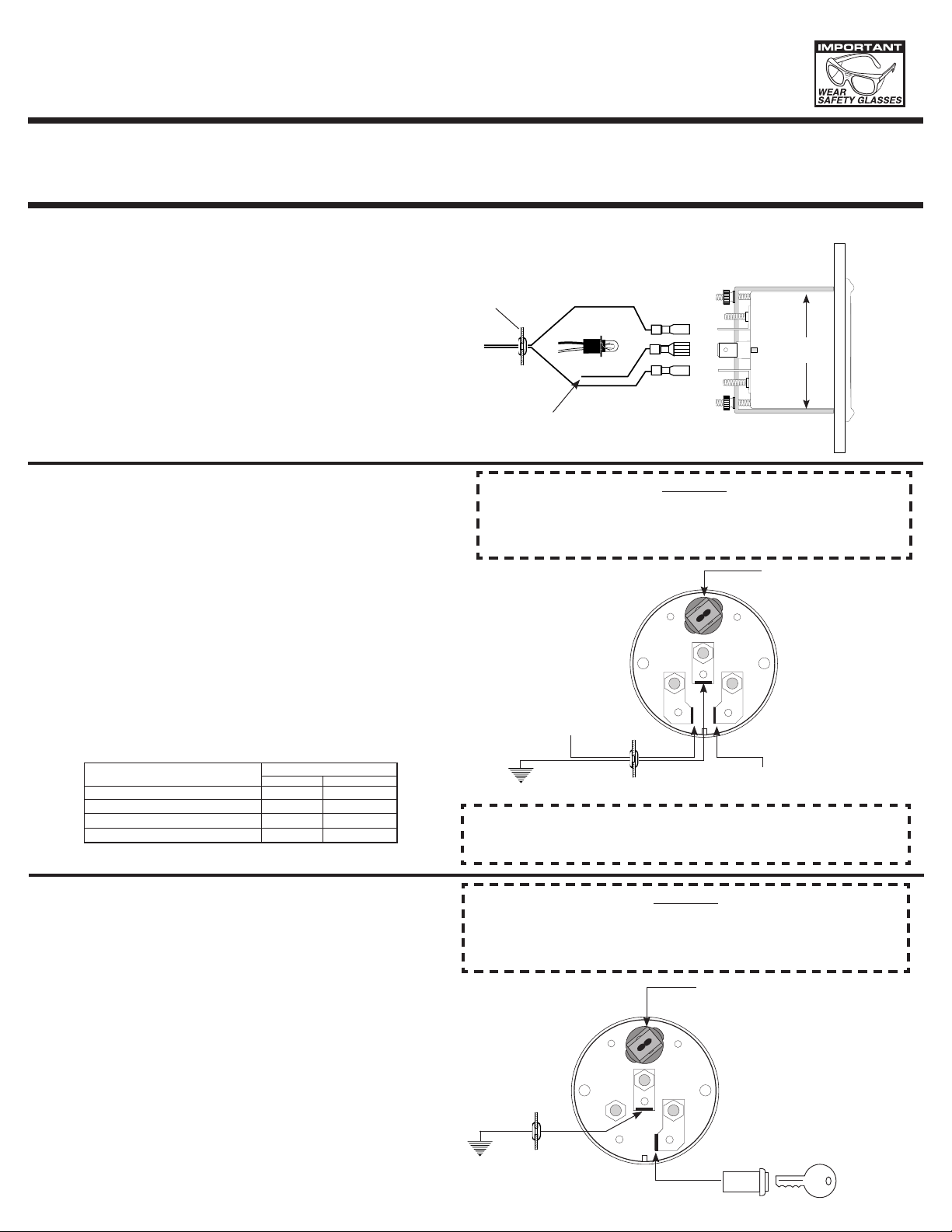
Mounting
These gauges can be mounted in a 2 1⁄16" dia. hole or in a standard
aftermarket street rod panel. Fasten with brackets supplied as shown.
(Hookup wire is required.) To assure proper functioning of this instrument, please read instructions thoroughly before installing.
NOTE: Some late model vehicles use electronic sensors in their
pressure and temperature senders for engine control functions. Before removing the original sender, we recommend
that you contact your automotive dealer to be sure no
critical functions will be disrupted. With pressure gauges
it is beneficial to add a T-fitting to install your new gauge
and to keep the warning light operational. This allows you
to monitor the pressure and still have a warning light to
indicate emergency conditions.
Fuel Level
1. Disconnect negative (-) battery cable.
2. Gauge connects to fuel sender on fuel tank. Existing wires may be
used, or route proper length of 18 gauge, 2 conductor wire from
fuel tank to gauge. Connect one end to terminal post on fuel level
sender and the opposite end to the sender (S) terminal spade on
back of gauge. See illustration at right.
3. Connect wire from center terminal spade on back of gauge GND (-)
to ground on fuel tank.
4. Connect wire from ignition switch to the positive I (+) wire on the
back of gauge. See figure above.
5. Install light in back of gauge and connect one wire to dash lighting
circuit or to other 12V power source and connect other wire to (-)
negative ground.
6. Reconnect negative (-) battery cable.
QUESTIONS:
Grommet
To Good Dash
or Chassis
Ground.
As a safety precaution the Red wire of this product should be fused before connecting
it to the positive (+) side of the 12V DC battery. We recommend using a 4 Amp, 3AG
fast-acting type cartridge fuse (Littlefuse® # 312 004 or an equivalent) inline with the
Red wire of our product.
Connect to terminal post
on sender on fuel tank.
FRONT MOUNTING (BOTTOM VIEW)
Replace light bulb with the same
number bulb as the one removed.
Light
CAUTION!
21⁄16"
Twist-In Light
GAUGE
(back view)
#
MODEL
For most GM vehicles
For most Ford and Chrysler vehicles
Use 3262 Fuel level sender
For most GM vehicles before 1965
SENDER RESISTANCE (OHMS)
EMPTY
0
73
240
0
FULL
90
8-12
33
30
Voltmeter
1. Disconnect negative (-) battery cable.
2. Using 18 gauge wire, route one length through firewall using
grommet. Attach one end to the negative GND (-) spade terminal on back of gauge, and the opposite end to a good engine
ground. See illustration at right.
3. Attach one length of wire to the positive I (+) wire on back of
gauge and opposite end to 12V terminal on ignition switch or
other 12 power source.
4. Install light in back of gauge and connect one wire to dash
lighting circuit or to other 12V power source and connect other
wire to (-) negative ground.
5. Reconnect negative (-) battery cable.
To ignition switch
Ground
Grommet
CAUTION:
Be careful not to touch ignition wire to the sender terminal on
back of gauge or the sender will be damaged.
CAUTION!
As a safety precaution the Red wire of this product should be fused before connecting it
to the positive (+) side of the 12V DC battery. We recommend using a 4 Amp, 3AG fastacting type cartridge fuse (Littlefuse® # 312 004 or an equivalent) inline with the Red
wire of our product.
Twist-In Light
Grommet
To 12V Terminal on Ignition
Switch or other 12V source.
Ground
Page 2

GND
S I
Water Temperature
GND
S I
Twist-In Light
TEMPERATURE SENDER
As a safety precaution the Red wire of this product
CAUTION!
should be fused before connecting it to the positive
(+) side of the 12V DC battery. We recommend
using a 4 Amp, 3AG fast-acting type cartridge fuse
(Littlefuse® # 312 004 or an equivalent) inline with
the Red wire of our product.
1. Disconnect negative (-) battery cable.
2. Install water temperature sender. Remove stock sender for water
temperature indicator light and install new sender.
3. Route 18 gauge twin conductor wire through firewall using grommet.
Connect one end to terminal post on sender and opposite end to the
sender (S) terminal spade on back of gauge. See illustration above.
4. Connect wire from center terminal spade GND (-) on back of gauge to
a good engine ground.
5. Connect a wire from the ignition switch to the ignition ( I ) terminal
spade on back of gauge. See illustration above.
Oil Pressure
No. 2242 for Domestic
Cars with 1/8" NPT
Outlet. Ford uses 1/4"
NPT Adapter included.
CAUTION!
As a safety precaution the Red wire of this product
should be fused before connecting it to the positive
(+) side of the 12V DC battery. We recommend
using a 4 Amp, 3AG fast-acting type cartridge fuse
(Littlefuse® # 312 004 or an equivalent) inline with
the Red wire of our product.
PRESSURE
SENDER
GAUGE
(back view)
Grommet
To ignition switch
Ground
CAUTION:
Be careful not to touch ignition wire to the sender terminal
on back of gauge or the sender will be damaged.
6. Install light in back of gauge and connect one wire to dash lighting
circuit or to other 12V power source and connect other wire to (-)
negative ground.
7. Reconnect negative (-) battery cable.
Twist-In Light
GAUGE
(back view)
Grommet
To ignition switch
1. Disconnect negative (-) battery cable.
2. Remove stock sender for dash warning light and install gauge
adapter. Sender fits 1⁄8" NPT and comes with 1⁄4" NPT adapter. Sender
should automatically be grounded when installed. If not, proper
Ground
CAUTION:
Be careful not to touch ignition wire to the sender terminal
on back of gauge or the sender will be damaged.
ground connections should be made.
3. Route 18 gauge twin conductor wire through firewall using grommet.
Connect one end to terminal post on pressure sender, and opposite
end to the sender (S) terminal spade on back of gauge. See illustration above.
4. Connect wire from center terminal spade GND (-) on back of gauge to
engine ground near sender.
5. Connect a wire from the ignition switch to the ignition ( I ) terminal
spade on back of gauge.
6. Install light in back of gauge and connect one wire to dash lighting
circuit or to other 12V power source and connect other wire to (-)
negative ground.
7. Reconnect negative (-) battery cable.
SERVICE
For service send your product to Auto Meter in a well packed shipping carton. Please include a note explaining what the problem is along with your phone number. Please specify when you
need the product back. If you need it back immediately mark the outside of the box “RUSH REPAIR,” and Auto Meter will service product within two days after receiving it. ($10.00 charge will
be added to the cost of “RUSH REPAIR.”) If you are sending product back for Warranty adjustment, you must include a copy (or original) of your sales receipt from the place of purchase.
12 MONTH LIMITED WARRANTY
The manufacturer warrants to the consumer that this product will be free from defects in materials and workmanship for a period of twelve (12) months from the date of the original purchase. Products
that fail within this 12 month warranty period will be repaired or replaced at the manufacturer’s option to the consumer, when determined by the manufacturer that the product failed because of defects
in material or workmanship. This warranty is limited to the repair or replacement of parts in the instrument and the necessary labor done by the manufacturer to affect the repair or replacement of the
instrument. In no event shall this warranty exceed the original purchase price of the instrument, nor shall the manufacturer be responsible for special, incidental or consequential damages or costs
incurred due to failure of this product. Warranty claims to the manufacturer must be transportation prepaid and accompanied with dated proof of purchase. This warranty applies only to the original
purchaser of product and is non-transferable. All implied warranties shall be limited in duration to the said 12 month warranty period. Breaking the instrument seal, improper use or installation, accident,
water damage, abuse, unauthorized repairs or alterations voids this warranty. The manufacturer disclaims any liability for consequential damages due to breach of any written or implied warranty on all
products made by the manufacturer.
FOR SERVICE CONTACT: AUTO METER PRODUCTS Inc. 413 W. Elm St., Sycamore, IL 60178 USA (815)899-0801 or
© 2006 Auto Meter Products, Inc.
Email us at service@autometer.com
2650-1179 7/11/06
 Loading...