

Page 1

INSTALLATION INSTRUCTIONS
31/8" ELECTRIC SPEEDOMETER
2650-1184
If after completely reading these instructions you have questions regarding the operation or installation of your instrument(s),
please contact Auto Meter Technical Service at 815-899-0801.
You may also email us at service@autometer.com.
Additional information can also be found at http://www.autometer.com/tech_faq.aspx
General Information
This electric speedometer utilizes a LCD to display odometer and trip
odometer mileage. Momentarily pressing of the Trip/Reset button on the
dial window toggles the odometer/trip odometer information displayed
on the LCD. Pressing the button, while in trip mode, for more than two
seconds will reset the trip odometer. The odometer cannot be reset.
This Auto Meter electric speedometer is pre-calibrated for 16,000 pulses/
mile. When converting from a cable driven speedometer, no further
calibration is needed if:
Speedometer Senders
The speedometer is designed to operate with an electrical speed
sender. The speed senders signal impulse range must be between
500 and 400,000 pulses/mile. Any speed sender or electronic
module that meets the following two conditions can be used:
Mounting
Front
1. Mount the speedometer in a 3.156" (35⁄32") dia. hole in the
dashboard. (Be careful not to cut the hole too large.) It can also
be mounted in standard after market street rod panels.
2. Cut a 3⁄8" dia. hole in the firewall for the speedometer wires. Place
a rubber grommet in the hole and route the connector wires
through the grommet to the engine compartment.
3. Connect the speedometer wires as shown in the Wiring Section.
4. Secure the speedometer to the dashboard using the provided
bracket, thumbnuts and lockwashers.
NOTE: With the ignition switch off, the speedometer pointer may
not always rest at zero. This is normal. When engine is started,
pointer will position correctly.
WARNING
Incorrect hookup will damage speedometer and void
warranty. Please read these instructions.
QUESTIONS:
1. The transmission’s speedometer cable take off is 1000 RPM at 60
MPH. Most vehicles meet this requirement. If the vehicles tire size
and/or differential ratio has changed, the speedometer needs to
be recalibrated.
2. The vehicle is equipped with a 16-pulse/revolution sender.
(See Speedometer Senders below for available Auto Meter Senders.)
If the above conditions have not been met, the speedometer must be recalibrated.
(see calibration section)
NOTE: The odometer on this speedometer will read from 1 to 5 miles.
This is done during factory testing to insure optimum quality.
• Pulse rate generated proportional to vehicle speed.
• Output within the voltage ranges listed below:
2.0 to 16 V peak (Square Wave), 3 wire
2.0 to 120 V peak to peak (Sine Wave), 2 wire
Recommended Auto Meter Hall Effect (Square Wave), 3 wire 16 pulses
Per Revolution senders:
5291 Standard 7⁄8-18 thread
5292 Ford, plug in
3.300"
1
2
⁄ 4"
3.141" dia. (3
9
⁄ 64" ref.)
Side View
Once the speedometer is mounted and wired into the vehicle, the
speedometer should be tested to verify the electrical connections are
working properly. First, watch the speedometer’s pointer as the power
is applied. The pointer should first move to a midrange position, then
down to the zero box on the dial. This action verifies that power is
properly connected to the speedometer. The vehicle should be driven
some distance to verify the Vehicles Speed Sender (VSS) is connected
properly, and that the pointer moves. If the pointer does not move off the
zero box, verify the VSS is connected properly.
Calibration
(Only needed if the conditions in General Information
are not met.)
Calibration Range: 500 to 400,000 pulses/mile
1. Speedometer and sender must be installed.
2. To set the speedometer in calibration mode; press and hold the
Trip/Reset button while starting the engine, then release the
Trip/Reset button. The pointer will then move to full scale.
3. Go to the beginning of a known two-mile distance and stop. Press and
release the Trip/Reset button. The pointer will move to half scale and
is ready for calibration.
NOTE: The accuracy of the speedometer depends on the accuracy of the
measured two-mile distance.
4. Drive the two-mile distance and stop. Press and release the
Trip/Reset button. The calibration mode will be exited and the pointer
will return to 0 mph.
Calibration is complete!
This is a list of factors that can affect speedometer accuracy and
how to minimize them during calibration.
1. Tires slightly increase in diameter as vehicle speed increases.
To minimize this error drive at an average speed during
calibration. (Approx. 45 mph for most street vehicles. )
2. Tires slightly increase in diameter as air pressure is increased.
To minimize this error, check the tires to ensure correct air pressure.
3. The diameter of the tires change with vehicle load. Minimize this
error by having an average load in the vehicle during calibration.
4. Tire slippage. Minimize this error by not breaking traction.
5. Accuracy of 2 mile distance driven during calibration. Minimize
this error by verifying the distance.
NOTE:
Always recalibrate speedometer after any tire size or differential
ratio change.
Page 2
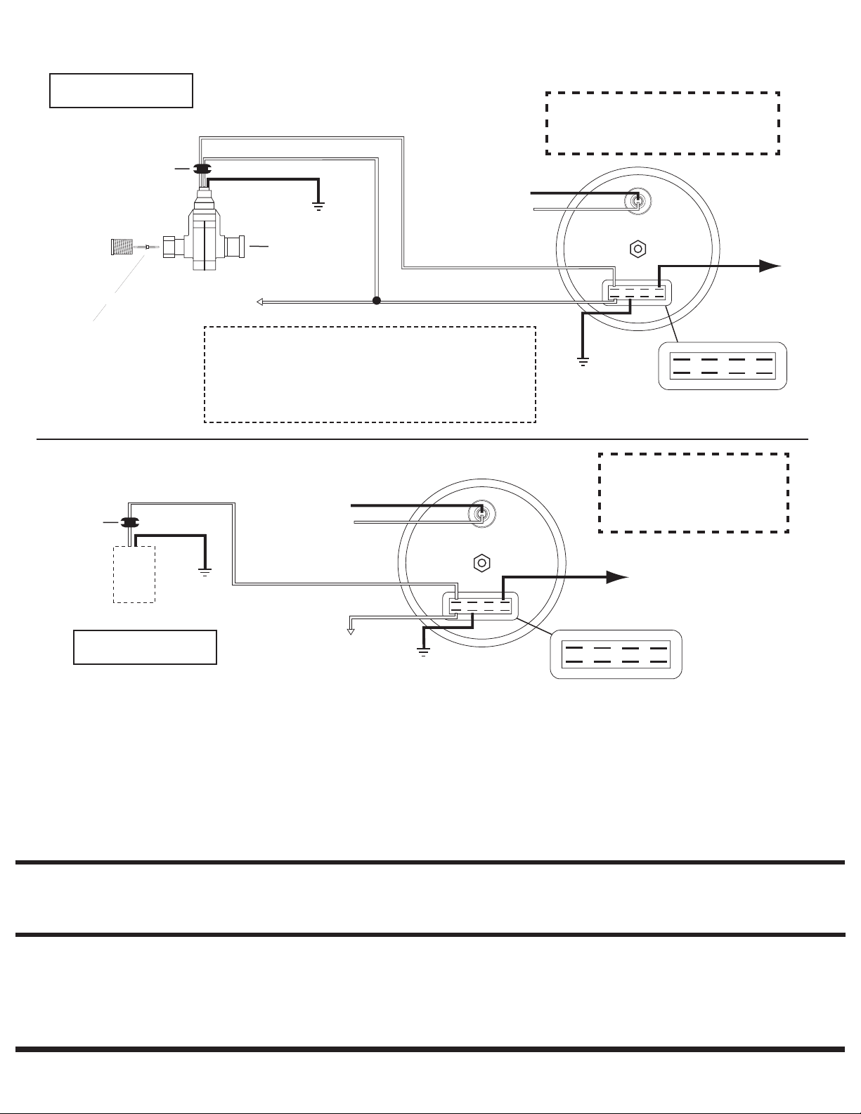
SIG.
+12V
LAMP
GND
GND
LAMP
OUT
+12V
To ground (-) negative
Light wire - dash lighting
circuit or 12 Volt (+)
Grommet
To +12 V
ignition source
GND
Back of
speedometer
Sine
Wave
2 Wire
Sender
GND
SIG.
+12V
LAMP
GND
GND
LAMP
OUT
+12V
SIG.
+12V
LAMP
GND
GND
LAMP
OUT
+12V
White (SQ)
To ground (-) negative
Light wire - dash lighting
circuit or 12 Volt (+)
Grommet
To +12 V ignition source
7/8-18 thread
Remove cap for cruise
control cable, otherwise
leave cap installed.
Transmission
take-off
GND
Red (+12 V)
Black (GND)
3-Wire Sender
Back of
speedometer
Drive Key
Supplied with .104 sq x .104 sq
GND
SIG.
+12V
LAMP
GND
GND
LAMP
OUT
+12V
Wiring
Use 20 AWG stranded or
heavier wire for hook-up
Auto Meter Hall-Effect senders (Square Wave)
- Models 5291 (standard 7/8-18 thread) & 5292 (For Plug in Sensor), 3 wire sender, cruise.
WARNING
This speedometer is not recommended
for vehicles with solid core ignition wires
To PCM/
Computer
(see Note)
NOTE: This speedometer provides an output (OUT) terminal that can
be used with late model vehicle installations using the existing Vehicle
Speed Sensor (VSS). In these installations, the VSS signal wire should
be connected to the SIG terminal of the speedometer only. The OUT
terminal should then be connected to where the VSS output was
originally wired. This will provide a buffered VSS signal to the PCM/
computer in the vehicle.
Most OEM style or Factory Installed, 2 wire senders (Sine Wave)
IMPORTANT
When using most OEM/factory
installed (2 wire) senders, you
must calibrate the speedometer
before it will function properly.
To PCM/
Computer
(see Note in
above section.)
Use 20 AWG stranded or
heavier wire for hook-up
For service send your product to Auto Meter in a well packed shipping carton. Please include a note explaining what the problem is along with your phone number. Please specify when you need the
product back. If you need it back immediately mark the outside of the box “RUSH REPAIR,” and Auto Meter will service product within two days after receiving it. ($10.00 charge will be added to the
cost of “RUSH REPAIR.”) If you are sending product back for Warranty adjustment, you must include a copy (or original) of your sales receipt from the place of purchase.
Products that fail within this 12 month warranty period will be repaired or replaced at Auto Meter’s option to the consumer, when it is determined by Auto Meter Products, Inc. that the
product failed due to defects in material or workmanship. This warranty is limited to the repair or replacement of parts in the Auto Meter instruments. In no event shall this warranty
exceed the original purchase price of the Auto Meter instruments nor shall Auto Meter Products, Inc. be responsible for special, incidental or consequential damages or costs incurred
due to the failure of this product. Warranty claims to Auto Meter must be transportation prepaid and accompanied with dated proof of purchase. This warranty applies only to the
original purchaser of product and is non-transferable. All implied warranties shall be limited in duration to the said 12 month warranty period. Breaking the instrument seal, improper
use or installation, accident, water damage, abuse, unauthorized repairs or alterations voids this warranty. Auto Meter Products, Inc. disclaims any liability for consequential damages
due to breach of any written or implied warranty on all products manufactured by Auto Meter.
FOR SERVICE CONTACT: AUTO METER PRODUCTS Inc. 413 W. Elm St., Sycamore, IL 60178 USA (815)899-0801 or
© 2006 Auto Meter Products, Inc.
SERVICE
12 MONTH LIMITED WARRANTY
Email us at service@autometer.com
2650-1184 7/24/06
 Loading...