

Page 1

INSTALLATION INSTRUCTIONS
TACH/SPEEDO COMBO
2650-1175-00 Rev. B
QUESTIONS:
If after completely reading these instructions you have questions regarding the operation or installation of your instrument(s),
please contact Auto Meter Technical Service at 815-899-0801.
You may also email us at service@autometer.com.
Additional information can also be found at http://www.autometer.com/tech_faq.aspx
General Information
The electronic speedometer in this instrument utilizes a single LCD to display odometer and two trip odometer mileages. Press the Trip/Reset button on the dial
window to cycle between odometer, Trip 1, and Trip 2 displays on the LCD. Pressing and holding the Trip/Reset button for more than 2 seconds while viewing
either Trip display will reset the trip currently being displayed. The odometer cannot be reset.
NOTE: The odometer on the speedometer portion of this instrument will show some mileage less than 5 miles (8km). This is a result of factory testing to ensure optimum quality.
TIP: Auto Meter always recommends performing the calibration process for best speedometer accuracy.
Speedometer Senders:
The electronic speedometer in this instrument is designed to operate with an electrical speed sender. The speed sender signal range must be between 500
and 400,000 pulses/mile (310 and 248,500 pulses/km). Any speed sender or electronic module that meets the following two conditions can be used:
1. Pulse rate generated is proportional to vehicle speed.
2. Output voltage within the ranges listed below:
a. Hall effect sender, 3 wire (5 to 16V)
b. Sine wave generator, 2-wire (1.4 VAC min.)
c. 5v Square Wave (CMOS)
Recommended – Auto Meter Hall effect sender, 3 wire, 16 pulses/revolution
5291 Standard 7/8” – 18 Thread
5292 Ford, plug in
Installation Tips
1. A 12 V power source MUST be used to power this tachometer. A 12V motorcycle battery is a good alternative for cars without batteries.
A battery with minimum 5 amp hour rating is recommended.
2. Wherever possible, solder wire connections and avoid crimp-type connectors. This will minimize loose connections that could cause problems later.
3. Make sure you have a good ground to engine and battery negative terminal.
4. Wire installations should be neat and tied down to prevent tugging and fraying of wires at connections.
Trouble Shooting
If your tach/speedo does not function properly after installation check the following:
1. Are all electrical connections correct and tight?
2. If neither the tach/speedo nor dial light work, check ground and
12V power connections.
3. Disregard tach/speedo readings that occur before engine is started.
4. If problems persist try the tach/speedo on another vehicle with the same ignition.
5. For changes in ignition type, contact a service representative from Auto Meter.
6. Ignition manufacturers recommend that the ignition and coil be matched according to criteria which they establish (often that the ignition and coil be
products of the same company). If they are mismatched, minor malfunctions may occur,showing as erratic readings on the tach. Mismatching
coil and ignition types are often the cause of incorrect tach performance.
Page 2
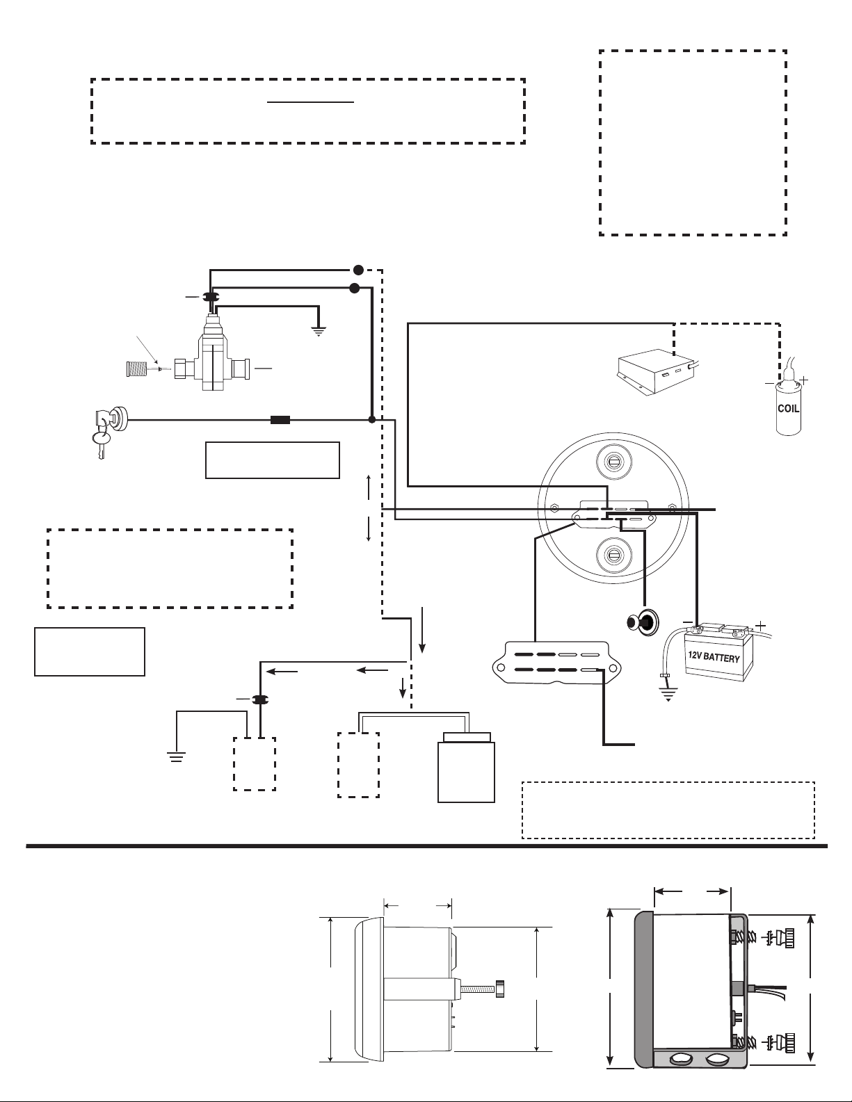
Wiring
SPEED
White
Grommet
7/8-18 thread
Remove cap for cruise
control cable, otherwise
leave cap installed.
On 5291 and 5292 Sender
Transmission
take-off
GND
FUSE
(SEE CAUTION)
Red
Black
3-Wire Sender
12V
IGNITION
SWITCH
Back of
speedometer
Drive Key
.104 sq x .104 sq
GND
12V DASH
LIGHTING
GND
+12V
GND
TACH
LAMP
VSS
+12V
Good Engine Ground
Grommet
SPEED
GND
+12V
GND
TACH
LAMP
VSS
+12V
(OR)
Electronic Ignition
Tach
Terminal
(OR)
Early Model
Ignition
CAUTION!
As a safety precaution, the power wire to this product should be fused before
connecting it to the positive (+) side of the 12 VDC battery. We recommend using a
1 Amp fuse.
Auto Meter Hall-Effect senders (Square Wave)
- Models 5291 (standard 7/8-18 thread) & 5292
(Ford Plug in Sensor), 3 wire sender, cruise.
Use 20 AWG stranded or
heavier wire for hook-up
WARNING
Warranty will be void if
connected to coil when using
an aftermarket ignition box
such as, but not limited to
products from the following
manufacturers: MSD, Crane,
Jacobs, Mallory, Holley, Etc..
Prior to installation of your
tachometer, check with the
ignition box manufacturer for
recommended tachometer
signal location.
Most OEM style or Factory Installed,
2 wire senders (Sine Wave)
Use 20 AWG
stranded or heavier
wire for hook-up
IMPORTANT
When using most OEM/factory installed
(2 wire) senders, you must calibrate the
speedometer before it will function properly.
GND
Mounting
1. Mount a 33⁄8" tach/speedo in a 33⁄8" dia. hole
and a 5" tach/speedo in a 45⁄8" dia. hole in the
dashboard. (be careful not to make the
hole too large.)
2. Cut a 3⁄8" dia. hole in the firewall for the
tach/speedo wires. Place a rubber grommet in
the hole and route the connector wires through
the grommet to the engine compartment.
3. Connect the tach/speedo wires as shown in the
wiring section.
4. Secure the tach/speedo to the dashboard using
the provided bracket, and hardware.
HI
LO
Sine
Wave
2 Wire
Sender
IF NO
COMPUTER
3¾"
OR
Sine
Wave
2 Wire
Sender
V.S.S.
33/8" Models
IF COMPUTER
CONTROLLED
TAP ONTO
HI-SIDE V.S.S.
SIGNAL
HI
LO
COMPUTER
1
2
/8"
PCM,
ECM,
VSS to ECM
(see Note)
Can use to power a 3 wire speed
sensor or another gauge
NOTE: The speedometer signal output terminal (VSS) produces
a +5 volt DC Square wave signal. This signal may be
able to be used as a VSS signal with some OEM and
aftermarket ECM’s and cruise control units.
11
3
/32"
5" Models
23⁄8"
415⁄16"
419⁄32"
Page 3

Operation
When power is first applied to the gauge, the odometer will display the current, PPM calibration, then the current, PPR calibration. Then it enters normal
operation mode and displays the odometer or trip miles, depending on the state of the odometer (total miles or trip) when it was last turned off.
Testing
Once the instrument is mounted and wired into the vehicle (see preceding page), the instrument should be tested to verify that the electrical
connections are working properly. First, watch the instrument’s pointers as power is applied with the key in the accessory position. The pointers
should first move to a midrange position, then down to the zero position on the dial. This action verifies that power is properly connected to the
instrument. Start engine. Tach should show idle RPM. The vehicle should be driven some distance to verify the Vehicle’s Speed Sender (VSS)
is connected properly and that the pointer moves. If the pointer does not move out of the zero position, verify that the VSS is connected properly
and that calibration has been performed
Calibration (Electronic Speedometer calibration made easy!)
To calibrate your electronic speedometer:
1) With the power off, push and hold the trip/reset button. While holding the button, start the vehicle and continue to hold the button until the pointer sweeps to full scale and
stays at full scale. You may now release the button.
2) Drive to the beginning of a pre-marked 2 mile distance and come to a stop. It does not matter how far away it is to get to this pre-marked 2 mile distance. DO NOT SHUT THE
ENGINE OFF. Push and release the button. The pointer will drop to half scale.
3) Drive the 2 mile distance. The pointer will remain at the half scale mark no matter what speed you drive. If the speedometer has a LCD display odometer, it will be normal to
see it counting rapidly as it is receiving a speed signal. If you have to stop during the calibration, that is o.k. The speedometer will simply stop counting pulses during this time.
4) At the end of the 2 mile distance, come to a complete stop and push and release the button. The pointer will drop to 0 and the calibration is stored. You are now finished.
Remember the accuracy of your 2 mile distance will directly affect the accuracy of your speedometer.
The following list contains factors that can affect speedometer accuracy and how to minimize them during calibration.
1. Tire diameter increases slightly as vehicle speed increases. To minimize this error drive at an average speed of 45 MPH (175 KPH) during calibration.
2. Tire diameter increases slightly as tire air pressure increases. To minimize this error, check the vehicle’s tires to ensure correct air pressure.
3. Tire diameter changes with vehicle load. Minimize this error by having an average load in the vehicle during calibration.
4. Minimize tire slippage error by not breaking traction during calibration.
Note: Always recalibrate your speedometer after any tire size or differential ratio change.
PPR (Tachometer Calibration)
With the power off, push and hold Odometer Trip button
While holding the button, turn power on to gauge by turning the key to the accessory position, and continue to hold trip button in while pointer
moves to 1/2 scale. Release the trip button once the pointer reaches 1/2 scale. The Odometer will show 0.5
NOTE: If the Trip button is held for 2 seconds or more, the gauge will enter PPM set mode. If this happens, press and release the Trip button. The
pointer will move to 1/2 scale. Press and realease the Trip button again. The pointer will move to the zero position. Turn off the power to the gauge
and repeat the PPR set procedure from the beginning.
The Odometer display will change, every 1.25 seconds to 1.0, then 1.5,2.0,2.5,3.0,3.5,4.0,4.5,5.0,5.5,6.0, and back to 0.5. It will continue to cycle
in this manner until the Trip button is pressed for 1 second and released. This enters the displayed PPR value and exits field cal mode.
ENGINE Most 2 cyl. Most 4 cyl. Most 6 cyl. Most 8 cyl.
PPR 0.5 1 1.5 2 2.5 3 3.5 4 4.5 5 5.5 6
For service send your product to Auto Meter in a well packed shipping carton. Please include a note explaining what the problem is along with your phone number. Please specify when you
need the product back. If you need it back immediately mark the outside of the box “RUSH REPAIR,” and Auto Meter will service product within two days after receiving it. ($10.00 charge will
be added to the cost of “RUSH REPAIR.”) If you are sending product back for Warranty adjustment, you must include a copy (or original) of your sales receipt from the place of purchase.
12 MONTH LIMITED WARRANTY
Auto Meter Products, Inc. warrants to the consumer that all Auto Meter High Performance products will be free from defects in material and workmanship for a period of twelve (12) months from date of the
original purchase. Products that fail within this 12 month warranty period will be repaired or replaced at Auto Meter’s option to the consumer, when it is determined by Auto Meter Products, Inc. that the product
failed due to defects in material or workmanship. This warranty is limited to the repair or replacement of parts in the Auto Meter instruments. In no event shall this warranty exceed the original purchase price of
the Auto Meter instruments nor shall Auto Meter Products, Inc. be responsible for special, incidental or consequential damages or costs incurred due to the failure of this product. Warranty claims to Auto Meter
must be transportation prepaid and accompanied with dated proof of purchase. This warranty applies only to the original purchaser of product and is non-transferable. All implied warranties shall be limited in
duration to the said 12 month warranty period. Breaking the instrument seal, improper use or installation, accident, water damage, abuse, unauthorized repairs or alterations voids this warranty. Auto Meter
Products, Inc. disclaims any liability for consequential damages due to breach of any written or implied warranty on all products manufactured by Auto Meter.
SERVICE
FOR SERVICE SEND TO: AUTO METER PRODUCTS, INC. 413 W. Elm St., Sycamore, IL 60178 USA (815) 899-0801
©2007 Auto Meter Products, Inc.
Email us at service@autometer.com
2650-1175-00 Rev. B 12/18/07
 Loading...