


C3 Camera
Hardware Reference
Manual
Rev. 1.3.7
Automation Technology GmbH


C3 Camera Hardware Reference Manual Rev. 1.3.7 • iii
Table Of Contents
Table Of Contents iii
Overview 2
Introduction................................................................................................... 2
Measuring Principle........................................................................................ 2
Geometry 1 .......................................................................................3
Geometry 2 .......................................................................................3
Geometry 3 .......................................................................................4
Geometry 4 .......................................................................................4
The C3 Camera Algorithms ............................................................................ 5
The Image Mode (IMG) ...................................................................... 5
The Maximum Intensity Profile Mode (MAX)........................................... 6
The Threshold Mode (TRSH) ................................................................7
The Center Of Gravity Mode (COG).................................................... 8
The Camera AOIs.......................................................................................... 9
The Image Data Output Format .................................................................... 10
The Data Channel Assignment DC0-DC2........................................... 10
Image Acquisition ........................................................................................ 11
Sensor Modes .................................................................................. 11
Trigger Modes.................................................................................. 13
The External Trigger Enable line ......................................................... 14
Output of internal Trigger and Status signals .................................................. 15
Software Integration of C3 Camera ............................................................... 16
Register Description 20
The C3 Camera Register Set ......................................................................... 20
Register Reference........................................................................................ 20
CFG_REG .......................................................................................20
CL_X0_REG ..................................................................................... 21
CL_DX_REG..................................................................................... 22
CL_DY_REG .................................................................................... 22
JTAG_REG....................................................................................... 22
ITIME_L_REG ................................................................................... 23
ITIME_H_REG .................................................................................. 23
IRTIME_L_REG .................................................................................23
IRTIME_H_REG ................................................................................24
PTIME_L_REG ..................................................................................24
PTIME_H_REG .................................................................................24

iv • C3 Camera Hardware Reference Manual Rev. 1.3.7
SENSOR_REG.................................................................................. 24
SENSOR_X0_REG ............................................................................25
SENSOR_DX_REG ............................................................................ 25
TRIG_CNT_REG............................................................................... 26
CL_CFG_ REG................................................................................. 26
HWINFO_REG................................................................................. 26
NUM_AOIS_REG ............................................................................. 27
LINLOG_VAL0_REG (obsolete, C3-A1024-CL only .............................27
LINLOG_VAL1 (obsolete, C3-A1024-CL only)..................................... 27
LINLOG_TIME_L_REG (obsolete, C3-A1024-CL only) ......................... 28
LINLOG_TIME_H_REG (obsolete, C3-A1024-CL only .........................28
ADC0_REG (obsolete, C3-A1024-CL only)......................................... 28
ADC2_REG (obsolete, C3-A1024-CL only)......................................... 29
CTRL_REG ....................................................................................... 29
STATUS_REG ................................................................................... 30
MUX_REG ....................................................................................... 30
MUX_TRIG_STATUS.......................................................................... 31
MUX_SENSOR_READOUT_TIME .......................................................31
MUX_FRAME_OUTPUT_TIME_L......................................................... 31
MUX_FRAME_OUTPUT_TIME_H........................................................ 32
MUX_CAP_INFO.............................................................................. 32
MUX_REVISION ...............................................................................32
IO_REG........................................................................................... 33
DATAOUT_REG ............................................................................... 33
AOI0_Y0-AOI7_Y0 ..........................................................................34
AOI0_DY-AOI7_DY ......................................................................... 35
AOI0_TRSH-AOI7_TRSH................................................................... 35
Sensor DAC Channels ...................................................................... 35
LASER_CONTROL_REG (C3-CompactSensors only) ............................ 36
WIDTH_VALID_MIN_REG.................................................................. 37
WIDTH_VALID_MAX_REG ................................................................. 37
SUM_INT_VALID_MIN_REG .............................................................. 37
SUM_INT_VALID_MAX_REG.............................................................. 37
I/O Interface 39
The Camera I/O Interface ............................................................................39
The internal DIP-Switches.............................................................................. 40
Description of LEDs ...................................................................................... 40
The External I/O Panel ................................................................................. 41
The CameraLink Interface of C3 Camera 42
System Overview.......................................................................................... 42
Supported CameraLink Modes ...................................................................... 42
Output Modes of C3 Camera with CameraLink Interface ..................... 44
CameraLink Signal Assignment .......................................................... 44
Camera Control Signal Assignment.................................................... 44
The UART Configuration Protocol.................................................................. 45
CMD_WRITE_DAC ........................................................................... 45
CMD_WRITE_REG............................................................................ 45
CMD_READ_REG............................................................................. 46
CMD_PROM.................................................................................... 46
The CameraLink Connection......................................................................... 47

C3 Camera Hardware Reference Manual Rev. 1.3.7 • v
Technical Specifications 49
C3-1280-CL Sensor..................................................................................... 49
C3-2350-CL Sensor..................................................................................... 51
Operating Specifications .............................................................................. 53
Camera Specifications ......................................................................53
Electrical Specification of I/O Signals .................................................53
Mechanical Specifications............................................................................. 54
Service Information 55
Document Revision ......................................................................................55
Product Information and Updates .................................................................. 55
Warranty Conditions .................................................................................... 56
Index 57


C3 Camera Hardware Reference Manual Rev. 1.3.7 Table Of Contents • 1
© 2009 Automation Technology GmbH.
All rights reserved. No part of this document shall be reproduced, stored in a retrieval system, or
transmitted by any means, electronic, mechanical, photocopying, recording, or otherwise without
consent in writing from the owners, AT-Automation Technology GmbH.
Disclaimer
While care has been exercised in the preparation of this document to ensure that it is fully correct and
comprehensive, the owners assume no responsibility for errors or omissions. Neither is any liability
assumed for damages resulting from the use of the information contained herein. No license is
granted under any patents or patent right of AT – Automation Technology GmbH.
Trademarks
3M™ is a registered trademark of the 3M Company.
Camera Link™ is a registered trademark of PULNIX America, Inc.
Channel Link™ is a registered trademark of National Semiconductor, Inc.
Matrox™ is a registered trademark of Matrox Electronic Systems Ltd.
LINLOG™ is a registered trademark of Photonfocus AG
All other nationally and internationally recognized trademarks and tradenames are hereby
acknowledged.
This document is subject to change without notification. All rights reserved.

2 • Overview C3 Camera Hardware Reference Manual Rev. 1.3.7
Overview
Introduction
The C3 camera series is a revolutionary product family of high speed intelligent sensors. It is optimised
for 3D shape measurement by means of laser triangulation technique. The 3D profile extraction is
performed in the camera by using high performance parallel hardware processors. At the same time
only the 3D profile data is sent to the PC over a standard interface (CameraLink). This extreme data
reduction boosts the measuring speed to unprecedented levels without affecting the performance of
the connected image processing unit.
Measuring Principle
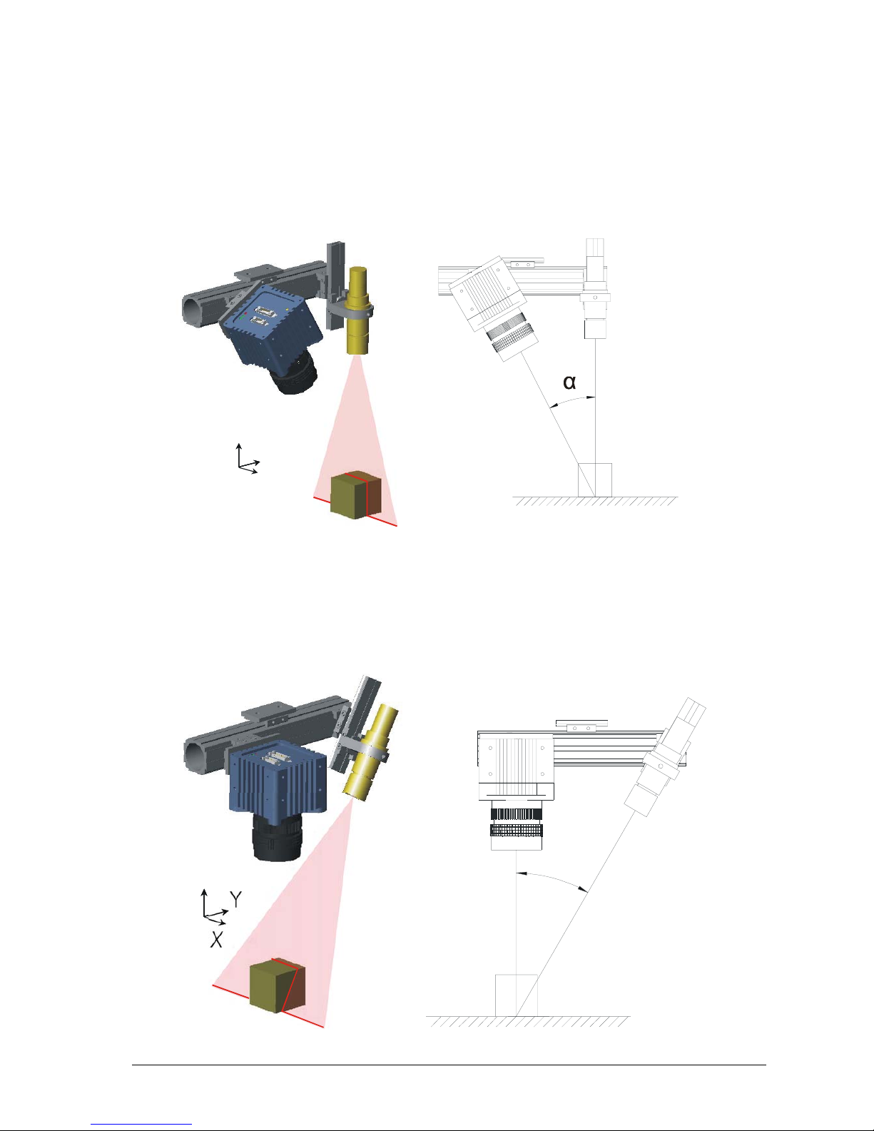
The C3 camera acquires height profiles and height images based on the laser triangulation principle.
According to this method a laser line is projected on the object from one direction. The C3 camera
views the object from another angle defining the triangulation geometry. The resulting sensor image is
evaluated by the C3 camera core and converted into a single height profile. By scanning the laser line
over the object a complete height image can be acquired.
The figures below demonstrate some typical triangulation geometries. The following notation is used in
the approximation of height resolution:
∆X= resolution along the laser line (lateral),
∆Y= resolution perpendicular to the laser line (longitudinal in the direction of motion),
∆Z= height resolution.
C3 Camera Hardware Reference Manual Rev. 1.3.7 Overview • 3
Geometry 1
The laser line is projected perpendicular to the object surface, while the camera views the object under
the triangulation angle α.
The height resolution can be approximated: ∆Z ≈ ∆X / sin(α)
Y
X
Z
Geometry 2
The camera views the object perpendicularly to its surface, while the laser line is projected under the
triangulation angle α.
The height resolution can be approximated: ∆Z ≈ ∆X / tan(α)
α
Y
X
Z

4 • Overview C3 Camera Hardware Reference Manual Rev. 1.3.7
Geometry 3
The camera views the object under an angle α, while the laser line is projected under a different
angle β.
The height resolution can be approximated: ∆Z ≈ ∆X * cos(β) / sin(α + β),
in case α= β (direct reflex) : ∆Z ≈ ∆X / 2* sin(α)
α
β
Y
X
Z
Geometry 4
The camera views the object under an angle α, while the laser line is projected under a different
angle β at the camera side.
The height resolution can be approximated: ∆Z ≈ ∆X * cos(β) / sin(α - β),
Y
X
Z
α
β

C3 Camera Hardware Reference Manual Rev. 1.3.7 Overview • 5
The C3 Camera Algorithms
The C3 camera can be operated both in a variety of 3D profile modes and in image mode. The
current operation mode can be chosen by setting the configuration bits of the CFG register.
The frame rate can be increased in all camera modes by reducing the AOI size. In the image mode
the frame rate is limited by the output rate of the camera interface (CameraLink). However, due to
reduced data size in profile mode the frame rate is limited only by the sensor output rate. As a matter
of principle the processing speed is independent of the chosen profile mode and is determined by the
AOI size.
In all profile modes only intensity values higher than the AOI intensity threshold AOI_TRSH
are
processed in order to suppress weak signal noise. In case that no position value can be found, e.g. no
intensity value is higher than threshold, the position value 0 is returned.
The Image Mode (IMG)
In the image mode the C3 camera is operated similar to a standard CMOS camera. In this mode grey
scale data of 8 or 10 bit resolution are acquired over the camera interface. Furthermore, the sensor
can be divided into multiple regions, whose data can be summarised in one output frame (see section
The Camera AOIs
for details).
6 • Overview C3 Camera Hardware Reference Manual Rev. 1.3.7
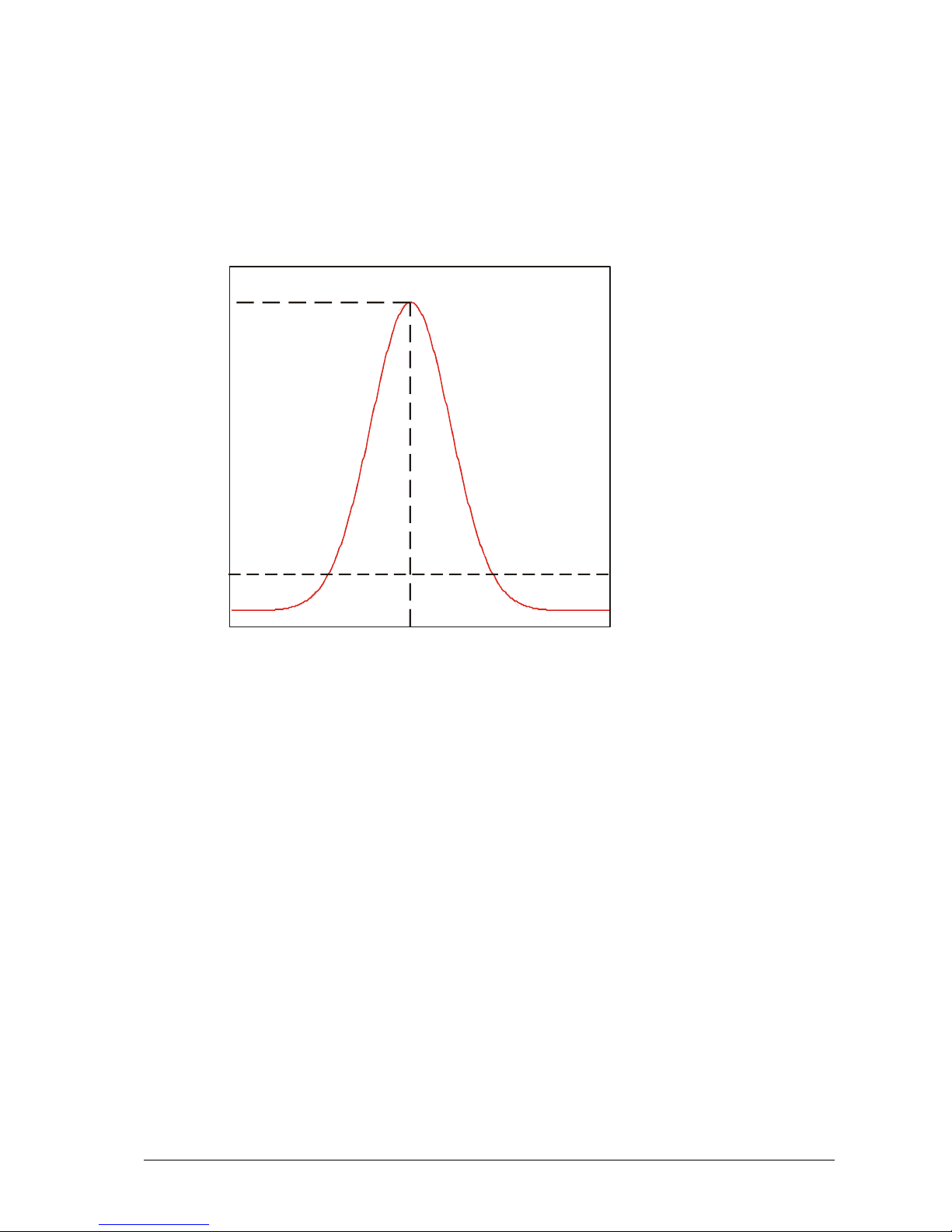
The Maximum Intensity Profile Mode (MAX)
In this mode the position of the maximum intensity of laser beam profile is calculated. The result
includes the position value of the maximum (P
MAX
) as well as the maximum intensity value (I
MAX
).
AOI_TRSH
P
MA
X
I
MAX
P
R
The calculation of position value is performed with simple pixel accuracy, i.e. the evaluation of 1024
rows delivers a position range from 0 to 1023 pixels (10 bit). If there is more than one local
maximum, the position of the first maximum (starting from row zero) is used.
C3 Camera Hardware Reference Manual Rev. 1.3.7 Overview • 7
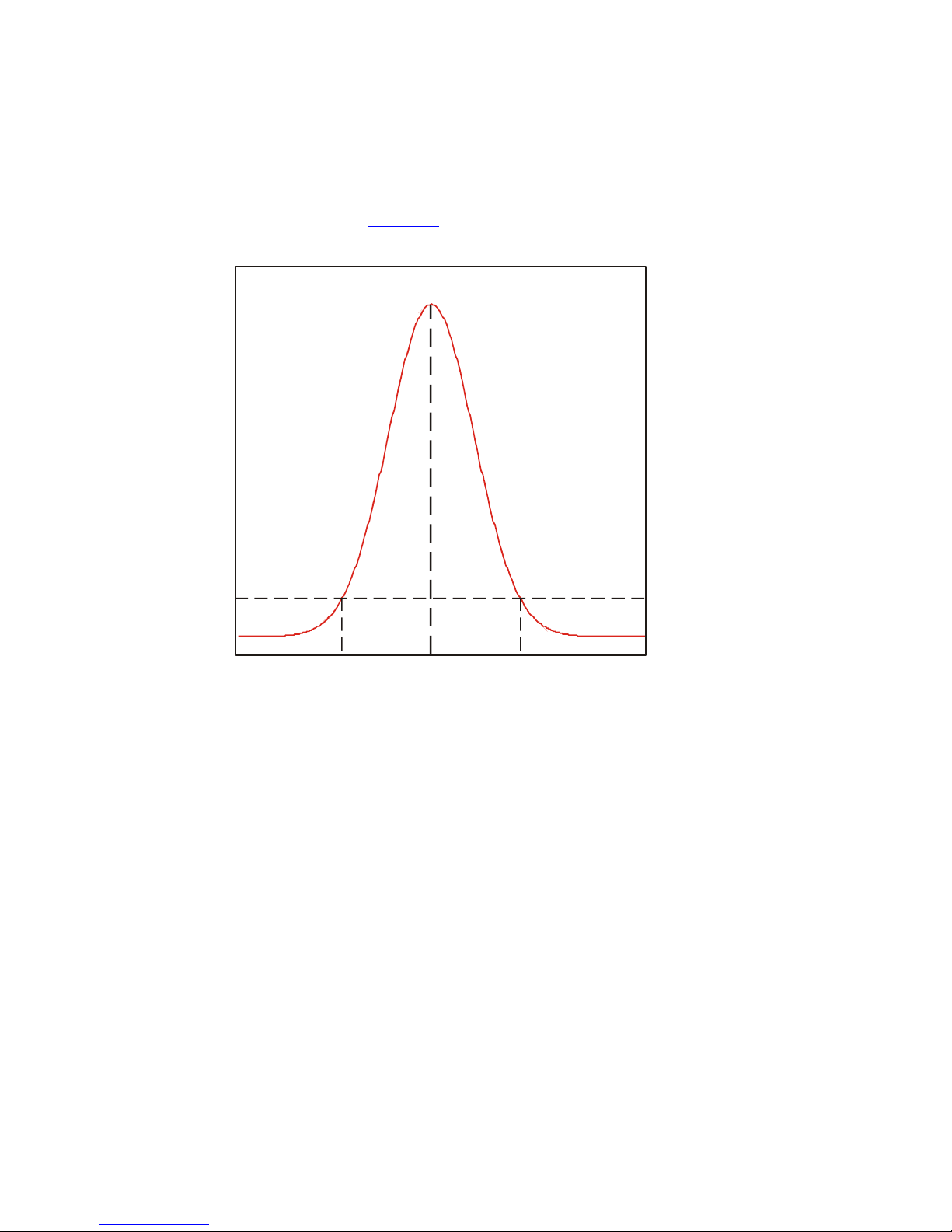
The Threshold Mode (TRSH)
In this mode the left (PL) and (PR) right edge position of the laser beam profile are calculated for a
given threshold value of intensity AOI_TRSH
.
AOI_TRSH
P
TRSH
P
L
P
R
The position value of the laser line is approximated: P
TRSH
= (PL+PR) / 2. In order to simplify the digital
representation the division over 2 is not performed and thus an integer representation with one
subpixel is realised. The evaluation of 1024 rows delivers a position range from 0 to 2047 pixels
(11 bit).
In threshold mode the camera can output either the left and right threshold position separately or the
subpixel position (P
L+PR
) and the line width (PR-PL). Moreover, the maximum intensity value can be
optionally delivered.

8 • Overview C3 Camera Hardware Reference Manual Rev. 1.3.7
The Center Of Gravity Mode (COG)
In this mode the center of gravity of laser beam profile is calculated. For this purpose the following
parameters are computed:
Position value of the left edge of laser beam profile for a given intensity threshold value P
L
,
Sum of intensity value I
s
= ∑ Ip,
Sum of first order moment M
s
= ∑Ip * P .
AOI_TRSH
P
CO
G
P
L
I
S
The position value of laser line (center of gravity of beam profile) is then obtained from:
P
COG
= PL + Ms / Is .
In addition the laser line width can be delivered over the Data Channel DC1
. The average intensity of
the illumination profile can be calculated by normalising the sum of intensity value I
s
with the line
width.
C3 Camera Hardware Reference Manual Rev. 1.3.7 Overview • 9
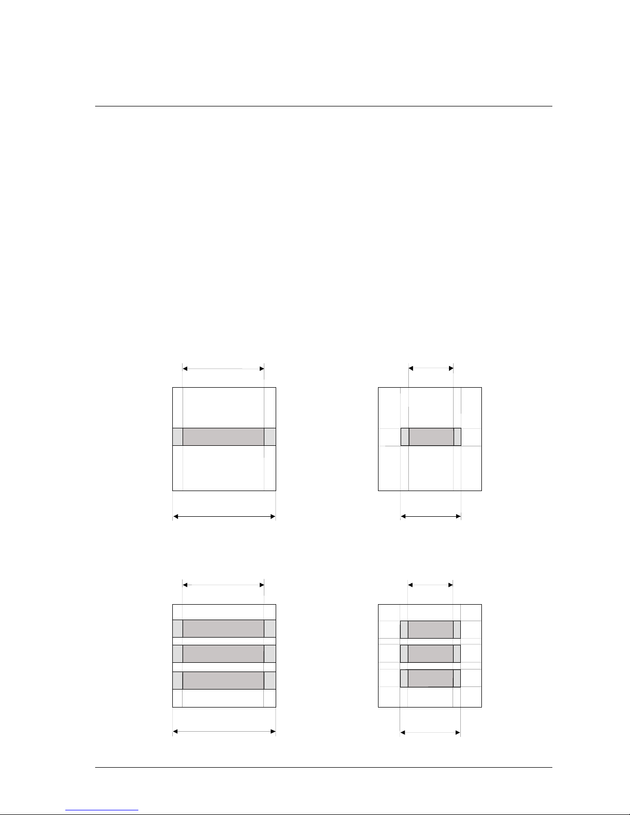
The Camera AOIs
The C3 camera series supports the operation of up to 8 none overlapping sensor Areas of Interest
(AOIs). Every AOI is defined by its starting row and total number of rows. A reduction of the AOI size
increases linearly the maximum frame rate. The AOI configuration is performed through the register
AOIX_Y0 and AOIX_DY. The camera outputs a single frame by putting together the individual AOIs.
Furthermore, the size of an AOI in the column direction can be also defined by setting the starting
column (CL_X0) and the number of output columns (CL_DX). Especially the camera C3-2350-CL
supports the reduction of the sensor output columns. For this sensor the read out speed and thus the
maximum frame rate increases linearly by reducing the number of pixels per row. Both the output
column position (CL_X0, CL_DX) and the sensor read out column position (SENSOR_X0, SENSOR_DX)
apply for all AOIs.
(0,0)
(1279,1023)
(0,0)
(1279,1023)
(0,0)
(1023,1023)
/
(2351,1727)
(0,0)
(1023,1023)
Length of sensor read out ro
w
Length of sensor read out row
Length of senso
r
read out row
(SENSOR_DX)
Length o
f
camera output row
(CL_DX)
A
OI0_Y0
A
OI0_Y0 + AOI0_DY
A
OI0_Y0
A
OI0_Y0 + AOI0_DY
A
OI0_Y0
A
OI0_Y0 + AOI0_DY
A
OI1_Y0
A
OI1_Y0 + AOI1_DY
A
OI2_Y0
A
OI2_Y0 + AOI2_DY
A
OI0_Y0
A
OI0_Y0 + AOI0_DY
A
OI1_Y0
A
OI1_Y0 + AOI1_DY
A
OI2_Y0
A
OI2_Y0 + AOI2_DY
12790
1279
0
Length o
f
camera output row
(CL_DX)
Length o
f
camera output row
(CL_DX)
Length o
f
camera output row
(CL_DX)
Length of senso
r
read out row
(SENSOR_DX)
SENSOR_X0
SENSOR_X0
CL_X0
CL_X0
CL_X0
CL_X0
SENSOR_X0
SENSOR_X0
C3-1280-CL C3-2350-CL

10 • Overview C3 Camera Hardware Reference Manual Rev. 1.3.7
The Image Data Output Format
The image and profile data output is performed by selecting the data channel DC0-DC2 (see
DATAOUT_REG
). Depending on the algorithm the data can be acquired by enabling the
corresponding output channel. Every channel is saved in a new image row. The data output can be
performed in 8 or 16 bit mode. In the 8 bit mode the DC0 (DATAOUT_DC0_SHIFT)
can be
configured to deliver the 8 most significant bits of the 10 bit intensity data. For the other channels the
8 most significant data bits are ignored.
In the CameraLink version with the compressed data output it is possible to use the CameraLink 2 tap
mode, in which two successive Pixel of 12 bit data width (DATAOUT_12BIT
) are transferred in one
cycle.
The Data Channel Assignment DC0-DC2
Alg. DC0 DC1 DC2
IMG Grey scale values Not used Not used
TRSH Maximum intensity Left edge of laser line
(PosL) or line width
(PosR-PosL)
Right edge of laser line (PosR) or
line position with 1/2 pixel
accuracy (PosL+PosR)
MAX Maximum intensity Left edge of laser line
(PosL)
Position of maximum intensity
(PosM)
COG
Sum of intensity values Is
Left edge of laser line
(PosL) or laser line width
(PosR-PosL)
Line position with 1/X pixel
resolution, where
X=1,2,4,8,16,32,64
Alg. Flags – Output over DC1 (16 bit mode):
Bit14 = LEFT_TRSH_FOUND_FLAG: indicates that the left edge of laser line was found
Bit15 = RIGHT_TRSH_FOUND_FLAG: indicates that the right edge of laser line was found

C3 Camera Hardware Reference Manual Rev. 1.3.7 Overview • 11
Image Acquisition
Sensor Modes
Freerun, untriggered Interleaved Mode (C3-1280-CL)
In this mode the acquisition (exposure) of the current image and the readout/processing of the
previous image is performed in parallel without external trigger. In 3D profile mode the maximum
frame rate is determined by the integration time or readout time of the sensor (whichever is longer).
On the contrary, in image mode the maximum frame rate is determined by the output time or
integration time of the sensor (whichever is longer). Comparing to readout or output time the
integration time (ITIME
) can be reduced by the parameter IRTIME (µs).
Integration
Frame N
Sensor Readout +
Output Frame N
Integration
Frame N+1
Output
Profile N
Sensor Readout +
Output Frame N+1
Integration
Frame N+2
3D Profile Mode
Image Mode
Sensor Readout
Frame N
Output
Profile N+1
Sensor Readout
Frame N+1
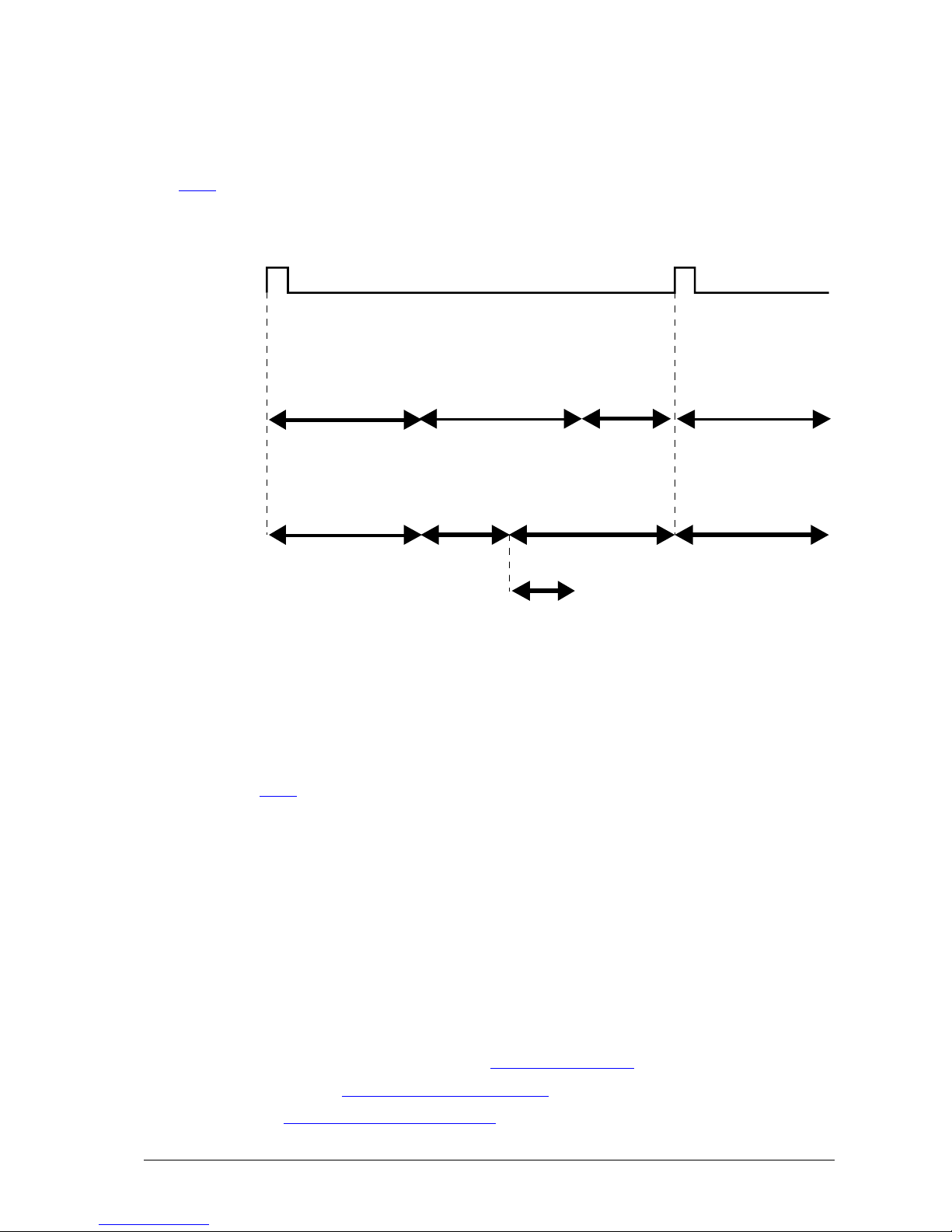
Triggered Interleaved Mode (C3-1280-CL)
In this mode the acquisition of the current image and the readout/processing of the previous image
can be performed in parallel depending on an external trigger. The maximum profile rate (camera is
running in profile mode) is determined by the sensor integration time and the sensor readout time. The
greater of both values corresponds to the time for the acquisition of one profile. In order to achieve a
constant integration time, even for asynchronous trigger pulses (e.g. from resolver interface) an
integration time greater or equal to the sensor readout time is recommended.

12 • Overview C3 Camera Hardware Reference Manual Rev. 1.3.7
Integration
Frame N
Sensor Readout
Frame N
Integration
Frame N+1
Output
Profile N
Sensor Readout
Frame N+1
Integration
Frame N+2
Output
Profile N+1
3D Profile Mode
Image Mode
external trigger (e.g. from digital input CC1 or
resolver interface ENC_A, ENC_B)
Sensor Readout +
Output Frame N
Sensor Readout +
Output Frame N+1
Freerun, untriggered Sequential Mode (C3-1280-CL)
In this mode the acquisition (exposure) and the readout / processing of the current image is performed
successively and without external trigger. The integration time is independent of the sensor readout
time and is determined only by the preset time ITIME
. In order to implement a predefined frame rate a
pause time (PTIME
) can by optionally used.
Integration
Frame N
Sensor Readout +
Frame N
optional
Pause Time
Integration
Frame N+1
Integration
Frame N
Sensor Readout
Frame N
optional
Pause Time
Integration
Frame N+1
Output
Profile N
3D Profile Mode
Image Mode
C3 Camera Hardware Reference Manual Rev. 1.3.7 Overview • 13
Triggered Sequential Mode (C3-1280-CL)
In this mode an external trigger initiates the image acquisition followed by the readout / processing.
The integration time is independent of the sensor readout time and is determined only by the preset
time ITIME
.
Pause Time
external trigger (e.g. from digital input CC1 or
resolver interface ENC_A, ENC_B)
Integration
Frame N
Sensor Readout +
Output Frame N
Integration
Frame N+1
Integration
Frame N
Sensor Readout
Frame N
Integration
Frame N+1
Output
Profile N
3D Profile Mode
Image Mode
Pause Time
Rolling Shutter, freerun (C3-2350 only)
In this mode the acquisition (exposure) of the current image and the readout/processing of the
previous image is performed row by row in parallel without external trigger. In 3D profile mode the
maximum frame rate is determined by the integration time or readout time of the sensor (whichever is
longer). On the contrary, in image mode the maximum frame rate is determined by the output time or
integration time of the sensor (whichever is longer). Comparing to readout or output time the
integration time (ITIME
) can be reduced by enabling the “Short Integration Mode”.
Rolling Shutter, triggered (C3-2350-CL only)
In this mode the acquisition of the current image and the readout/processing of the previous image
can be performed in parallel depending on an external trigger. The maximum profile rate in 3D mode
is determined by the integration time or readout time of the sensor (whichever is longer).
Trigger Modes
Image Acquisition Start
The image acquisition is initiated by a trigger when CFG_SEQ_FREERUN = 0 and
- „Start – Input“, when IO_START_STOP_SEQ_IO_EN
= 1 or
- CC(2) when IO_START_STOP_SEQ_CC_EN
= 1 or

14 • Overview C3 Camera Hardware Reference Manual Rev. 1.3.7
- CTRL_START bit of CTRL register
Image Acquisition Stop
The image acquisition is stopped by a trigger when CFG_SEQ_FREERUN = 0 and
- „Stop – Input“, when IO_START_STOP_SEQ_IO_EN
= 1 or
- CC(3) when IO_START_STOP_SEQ_CC_EN
= 1 or
- CTRL_STOP
bit of CTRL registers or
- automatic stop when a frame end is reached CFG_STOP_AT_FRAME_END
= 1
Profile Acquisition in 3D Profile Mode
The sensor integration or profile output is initiated by a trigger when CFG_INTEG_FREERUN = 0 and
- TRIG_CNT_MODE
= 0, use external trigger:
o „Start – Input“, when IO_TRIGGER_IO_EN
= 1, or
o CC(1), when IO_TRIGGER_CC_EN
= 1, or
o CTRL_TRIG
bit of CTRL register.
- TRIG_CNT_MODE
= 1, use external trigger of RS422 encoder interface.
External Triggering of Integration
The beginning and duration of sensor integration (exposure) can be determined by an external signal.
CFG_INTEG_FREERUN
= 0
CFG_EXT_INTEG_MODE
= 1
Use the following trigger:
- integration is active while IN1=H, when IO_TRIGGER_IO_EN
= 1, or
- integration is active while CC1=1, when IO_TRIGGER_CC_EN
= 1.
The External Trigger Enable line
By using camera input IN2 or the CameraLink line CC4 the internal trigger signal can be enabled or
disabled. This behaviour can be enabled by setting the corresponding configuration bits
(IO_TRIGGER_IO_EN
, IO_TRIGGER_CC_EN). With this signal any external trigger inputs (e.g.
resolver interface, camera input IN1 or CC1) can be enabled or disabled. At every low to high
transition of the trigger enable signal the trigger counter
is loaded with its start value. After a high to
low transition of the trigger enable line the currently active profile acquisition will be normally finished.
In free-run (untriggered) mode the external trigger enable signal enables the acquisition.
The external trigger enable has no function in external integration time control mode.

C3 Camera Hardware Reference Manual Rev. 1.3.7 Overview • 15
Output of internal Trigger and Status signals
The internal trigger and status signals can be monitored by using the digital outputs OUT1 and OUT2.
Setting IO_OUT2
to IO_OUT2_CNT_ZERO leads to the output of the internal trigger signal
generated from the resolver interface depending on the trigger count value TRIG_CNT
.
See Description of IO_REG
for further options.
A trigger overrun during external triggering can be detected by reading the TRIG_OVERRUN
flag of
the status register. This flag is set to one if a trigger pulse occurred during an active integration. By
means of this flag one can verify if the preset trigger count value is sufficient for the speed of an
external resolver and no trigger pulses are lost. The trigger overrun flag can be cleared by writing the
CTRL_TRIG_OVERRUN_CLR
bit.

16 • Overview C3 Camera Hardware Reference Manual Rev. 1.3.7
Software Integration of C3 Camera
There are four possible ways to integrate the C3 camera in a software application.
1. Operation as a Standard CameraLink-Camera in combination with One-Off Configuration
In this case the C3 camera is configured with the software tool “C3Explorer” and the configuration is
saved permanently in the camera EEPROM. This default configuration will be loaded automatically
each time the camera is connected to power.
For image acquisition, the camera can be operated as a standard CameraLink camera without any
additional camera specific configuration interface. The programming is limited to the application
specific image processing making use of library (e.g. SAPERA, IFC, MIL, MULTICAM, NI-IMAQ), which
supports the selected frame grabber.
User - Application
Image Processing Lib
with Frame Grabber API
(eg. SAPERA, MIL, CVB)
Frame Grabber driver
CameraLink Frame Grabber
Camera Image,
Height Image
Configuration Software,
eg. “C3-Explorer”
Offline C3-Camera
Configuration
C3Lib UART DLL
with UART interface
UART-Serial driver
Camera
Configuration
C3-Camera

C3 Camera Hardware Reference Manual Rev. 1.3.7 Overview • 17
2. Operation as a Standard CameraLink-Camera in combination with Serial Configuration (CLSER or
UART Protocol)
In this case the camera configuration can be modified by the application software using the CLSER or
UART protocol for serial communications. The provided CLSER/UART DLL can be used for the
implementation of camera specific protocol. Similar to case 1, the frame grabber can be accessed by
making use of a standard image processing library:
User - Application
C3Lib UART DLL
with UART interface
Image Processing Lib
with Frame Grabber API
(eg. SAPERA, MIL, CVB)
UART-Serial driver Frame Grabber driver
CameraLink Frame Grabber
Camera
Configuration
Camera Image
,
Height Image
C3-Camera

18 • Overview C3 Camera Hardware Reference Manual Rev. 1.3.7
3. Operation using the C3Lib API for camera configuration and image acquisition
Alternatively, the C3Lib API with implemented functions for the access to frame grabber and camera
registers can be used:
User - Application
C3Lib DLL with
Configuration-
and Grab-Interface
Image Processing Lib
with Frame Grabber API
(eg. SAPERA, MIL, CVB)
UART-Serial driver Frame Grabber driver
CameraLink Frame Grabber
C3-Camera
Camera
Configuration
Camera Image,
Height Image
The C3Lib API supports the following frame grabbers:
Manufacturer Frame Grabber Image Processing Library
DALSA X64CL, X64CL-Ipro, X64CL-
IproLite, X64CL-Express, X64Xcelera-CL
SAPERA LT
Coreco (DALSA) PC-Camlink, PC2-Camlink IFC
Euresys Grablink Value, Grablink Expert Multicam
Matrox Meteor II/CL MIL
National Instruments PCI-1426, PCI-1428 NI-IMAQ
In addition, the C3Lib supports the Iport protocol of Pleora Technologies over Gigabit Ethernet
interface.

C3 Camera Hardware Reference Manual Rev. 1.3.7 Overview • 19
4. Camera configuration and image acquisition over GenIcam Transport Layer
A fourth method for integration of C3 camera in software applications is the use of the GenIcam API
standard with the XML functionality. Based on Dalsa X64CL-Ipro and Sapera library, AT has developed
a CameraLink Transport Layer, which allows the easy integration of C3 cameras into machine vision
applications. For each C3 camera model an XML parameter file is provided.
AT-CL Transport Layer
Camera Link Frame Grabber
Sapera CLAllSerial.dll
CLSerXXX.dll
CLProtocolC3.dll
C3 Camera XML
User Software
APIAPI

20 • Register Description C3 Camera Hardware Reference Manual Rev. 1.3.7
Register Description
The C3 Camera Register Set
The C3 camera can be configured by means of a programmable register set. In this way e.g. the
camera operation (image mode of 3D profile mode) can be changed by setting the register contents
to appropriate values. As a rule all registers have a data width of 16 bits. The register addressing takes
place in 16 bit steps, i.e. the address of register 0 is 0, the address of register 1 is 1 etc. The register
address space comprises 6 bits, which correspond to 64 possible register addresses.
The addresses 56-63 are reserved for the sensor DAC channels, which can be accessed over the
functions DacRead and DacWrite.
All camera settings can be saved as a start-up configuration in a parameter EEPROM, which is
integrated in the camera. There are 64 PROM addresses available and the addressing is similar to
that of register set. The parameter EEPROM can be accessed over a set of special functions:
PromRead, PromWrite and PromWriteEnable/Disable.
Register Reference
The individual registers of the C3 camera series are described in the following sections.
Unimplemented register addresses and bits are presently not used and are for future enhancements
reserved. The return value of unimplemented register bits is undefined.
CFG_REG
Description
Address: 0
Access: R/W
Register Bit Description
Bit Bit Name Description
0 CFG_ALG_IMG Image mode
1 CFG_ALG_TRSH 3D profile mode: Threshold algorithm (TRSH)
2 CFG_ALG_MAX 3D profile mode: Maximum intensity algorithm (MAX)

C3 Camera Hardware Reference Manual Rev. 1.3.7 Register Description • 21
Bit Bit Name Description
3 CFG_ALG_COG 3D profile mode: Center of gravity algorithm (COG)
4 Reserved
5 CFG_ALG_TEST_IMAGE 1: Generates an artificial laser line image (Debug)
6 CFG_ALG_VERTICAL_INVERT 1: Flips the image vertically
7 CFG_ALG_CLEAR_INVALID_POS 1: Validates the position result of an image column
The validation is performed at the end of column evaluation
using tolerances for width and area of Gaussian intensity
distr ibut ion ( register C3_WIDTH_VALID_MIN_REG,
C3_WIDTH_VALID_MAX_REG,
C3_SUM_INT_VALID_MIN_REG ,C3_SUM_INT_VALID_MAX_REG)
Invalid results are suppressed and their values are set to 0 in all
DCs.
8 CFG_ALG_ABS_POS 1: Absolute row position is returned
0: Offset position with respect to the start row of AOI is returned
9 CFG_ALG_ POS_VALIDATION_EN 1: Validates every Gaussian curve detected along an image
column.
The validation is performed using tolerances for width and area
of Gaussian intensity distribution (register
C3_WIDTH_VALID_MIN_REG, C3_WIDTH_VALID_MAX_REG,
C3_SUM_INT_VALID_MIN_REG ,C3_SUM_INT_VALID_MAX_REG)
Invalid results are ignored.
If CFG_ALG_TRSH_FIRST_FALLING=0, then no validation of
minimum Gaussian area is performed (tolerance in register
C3_SUM_INT_VALID_MIN_REG).
10 CFG_ALG_TRSH_FIRST_FALLING 1: Stops the position evaluation after the falling edge of the first
valid detected Gaussian curve.
11 CFG_SEQ_FREERUN 1: Free-run image acquisition
0 : The image acquisition start is performed by a trigger
12 CFG_INTEG_FREERUN 1: Free-run integration / profile acquisition
0 : Triggered integration / profile acquisition
13 CFG_EXT_INTEG_MODE Triggers the sensor exposure. The integration lasts as long as an
external signal is applied.
14 CFG_START_STOP_MODE Use the external trigger to start / stop the sequencer
15 CFG_STOP_AT_FRAME_END Stop the sequencer when the frame end is reached
CL_X0_REG
Description
Address: 1
Access: R/W
This register defines the starting column of the output frame with respect to the internal buffer of the
camera.
Register Bit Description

22 • Register Description C3 Camera Hardware Reference Manual Rev. 1.3.7
Bit Bit
Name
Description
0-3 CL_X0_L C3-1280-CL: Bits 0-3 of starting column
C3-2350-CL: Bits 0-3 of starting column
4-11 CL_X0_H C3-1280-CL: Bits 4-10 of starting column
C3-2350-CL: Bits 4-11 of starting column
CL_DX_REG
Description
Address: 2
Access: R/W
Register Bit Description
Bit Bit
Name
Description
0-11 CL_DX Set the number of pixels per row (frame width).
CL_DY_REG
Description
Address: 3
Access: R/W
Register Bit Description
Bit Bit
Name
Description
0-15 CL_DY Set the number of output rows per frame.
JTAG_REG
Description
Address: 4
Access: R/W
Register Bit Description
The access to this register is reserved for commissioning and maintenance tasks of the
manufacturer.

C3 Camera Hardware Reference Manual Rev. 1.3.7 Register Description • 23
Bit Bit Name Description
0 JTAG_CFG_TDI Input of camera JTAG – Chain is connected to TDO Output of the last chip in JTAG-
Chain.
1 JTAG_CFG_TDO Output of camera JTAG-Chain is connected to TDI Input of the first chip in JTAG-Chain.
2 JTAG_CFG_TCK JTAG-TCK signal
3 JTAG_CFG_TMS JTAG-TMS signal
4 JTAG_CFG_ENABLE Enables JTAG port.
ITIME_L_REG
Description
Address: 5
Access: R/W
Register Bit Description
Bit Bit Name Description
0-15 ITIME_L Sensor integration time (low Word) in µs
ITIME_H_REG
Description
Address: 6
Access: R/W
Register Bit Description
Bit Bit Name Description
0-7 ITIME_H Sensor integration time (high Word).
IRTIME_L_REG
Description
Address: 7
Access: R/W
Register Bit Description
Bit Bit Name Description
0 – 15 IRTIME_L Reduction of sensor integration time (low Word) in µs
0-10 IRTIME C3-2350-CL only: Number of rows needed when „Short Integration Mode“ is enabled

24 • Register Description C3 Camera Hardware Reference Manual Rev. 1.3.7
IRTIME_H_REG
Description
Address: 8
Access: R/W
Register Bit Description
Bit Bit Name Description
0 – 7 IRTIME_H Reduction of sensor integration time (high Word)
PTIME_L_REG
Description
Address: 9
Access: R/W
Register Bit Description
Bit Bit Name Description
0 – 15 PTIME_L Pause time (low Word) in µs
PTIME_H_REG
Description
Address: 10
Access: R/W
Register Bit Description
Bit Bit Name Description
0 – 7 PTIME_H Pause time (high Word)
SENSOR_REG
Description
Address: 11
Access: R/W

C3 Camera Hardware Reference Manual Rev. 1.3.7 Register Description • 25
Register Bit Description
Bit Bit Name Description
0 CURR_ON
DARK_OFF_EN
obsolete (C3-A1024-CL)
C3-1280-CL only
1 HIGH_VB1 obsolete (C3-A1024-CL)
2 HIGH_VB2 obsolete (C3-A1024-CL)
3 HIGH_VB3 obsolete (C3-A1024-CL)
4 SENSOR_CORRECT_ECLIPSE 1: corrects the eclipse effect of CMOS sensor (C3-1280-CL only)
5 reserved always 0
6 SENSOR_DUMMY_ROW_EN obsolete (C3-A1024-CL)
7-8 SENSOR_SHUTTER_MODE SENSOR_INTERLEAVED = 0x0000, The sensor integration and readout is
performed in parallel
SENSOR_SHORT_INTEG_MODE = 0x0080 (C3-2350-CL only)
SENSOR_SEQ = 0x0100, Sequential acquisition: 1. Sensor integration, 2.
Sensor readout. 3. Pause when PTIME
> 0
9 SENSOR_SKIMMING_ON obsolete (C3-A1024-CL)
10 SENSOR_LINLOG_ON obsolete (C3-A1024-CL)
11 SENSOR_LOG_MODE obsolete (C3-A1024-CL)
15 SENSOR_STDBY 1 = low power mode, sensor is in standby
0 = sensor is active
SENSOR_X0_REG
Description
Address: 12
Access: R/W
Register Bit Description
Bit Bit Name Description
0-11 SENSOR_X0 Starting column of sensor readout, (C3-2350-CL only). For C3-1280-CL = 0.
SENSOR_DX_REG
Description
Address: 13
Access: R/W
Register Bit Description
Bit Bit Name Description
0-11 SENSOR_DX Row width of sensor readout (C3-2350-CL only). For C3-1280-CL = 1279.

26 • Register Description C3 Camera Hardware Reference Manual Rev. 1.3.7
TRIG_CNT_REG
Description
Address: 14
Access: R/W
Register Bit Description
Bit Bit Name Description
15 TRIG_CNT_BIDIR RS422 Resolver:
1= count resolver pulses in both directions
2 = count resolver pulses in positive direction only
14 TRIG_CNT_INV RS422 Resolver: reverse the resolver count direction
13 TRIG_CNT_CNT_MODE 1 = Use the counter output to trigger (i.e. to initiate the sensor integration)
0 = Use the external trigger input (i.e. to initiate the sensor integration)
12 TRIG_CNT_LOAD_AT_START Load the value from trigger counter TRIG_CNT when the next trigger
occurs
11,10 Reserved
9-0 TRIG_CNT Trigger counter
CL_CFG_ REG
Description
Adresse: 15
Zugriff: R/W
Registerbit Description
Bit Bit Name Description
15 CL_CFG_FVAL_PULSE 1= output of CameraLink FVAL-Signals as pulse
0 = output of CameraLink FVAL-Signals as Frame Enable-Signal
(default)
14 CL_CFG_LVAL_PULSE 1= output of CameraLink LVAL-Signals as pulse
0 =output of CameraLink LVAL-Signals as Line Enable-Signal (default)
13-8 CL_CFG_ROW_END_PAUSE number of additional CameraLink pulse at end of output row
7-0 CL_CFG_FRAME_END_PAUSE number of additional Anzahl CameraLink pulse at end of frame
HWINFO_REG
Description
Address: 16
Access: R/W

C3 Camera Hardware Reference Manual Rev. 1.3.7 Register Description • 27
Register Bit Description
NUM_AOIS_REG
Description
Address: 17
Access: R/W
Register Bit Description
Bit Bit Name Description
3-0 NUM_AOIS Number of used sensor AOIs –1
LINLOG_VAL0_REG (obsolete, C3-A1024-CL only
Description
Address: 18
Access: R/W
Register Bit Description
Bit Bit Name Description
0-9 LINLOG_VAL0 LINLOG-DAC-Value1 for LinLog2 mode. This value is enabled in the beginning of integration
and remains active until LINLOG_TIME expires.
LINLOG_VAL1 (obsolete, C3-A1024-CL only)
Description
Address: 19
Access: R/W
Register Bit Description
Bit Bit Name Description
0-3 HWINFO_NUM_AOIS Number of maximum definable sensor AOIs –1
4-7 HWINFO_PROM_SIZE Size of the internal CFG-PROM in 64 Words, i.e. 1=64 Words
8-11 HWINFO_CAM_TYPE HWINFO_CAM_1280 = 0100H = C3-1280-CL
HWINFO_CAM_1024 = 0200H = C3-A1024-CL
HWINFO_CAM_2350 = 0300H = C3-2350-CL
12-15 HWINFO_CAM_INTERFACE CameraLink Interface = 1000H

28 • Register Description C3 Camera Hardware Reference Manual Rev. 1.3.7
Bit Bit Name Description
0-9 LINLOG_VAL1 LINLOG-DAC-Value2 for LinLog2 mode. This value is enabled after the expiration of
LINLOG_TIME and remains active until the end of integration.
LINLOG_TIME_L_REG (obsolete, C3-A1024-CL only)
Description
Address: 20
Access: R/W
Register Bit Description
Bit Bit Name Description
0-15 LINLOG_TIME_L Time interval for LinLog2 mode (low Word) in µs.
LINLOG_TIME_H_REG (obsolete, C3-A1024-CL only
Description
Address: 21
Access: R/W
Register Bit Description
Bit Bit Name Description
0-7 LINLOG_TIME_H Time interval for LinLog2 mode (high Word) in 65535 µs.
ADC0_REG (obsolete, C3-A1024-CL only)
Description
Address: 22
Access: R/W
Register Bit Description
Bit Bit Name Description
0-4 ADC_A_GAIN ADC channel A Gain (0-1FH), 0=0dB, 1FH =18.06dB
5-9 ADC_B_GAIN ADC channel B Gain (0-1FH) , 0=0dB, 1FH =18.06dB
10 ADC_SELB always 0
11 ADC_MODE always 1
12 ADC_TWOS always 0
14-13 reserved always 0

C3 Camera Hardware Reference Manual Rev. 1.3.7 Register Description • 29
Bit Bit Name Description
15 ADC_LOAD 1 : load sensor ADC0_REG in ADC0 CHA/B and ADC1_REG in ADC1 CHA/B
ADC2_REG (obsolete, C3-A1024-CL only)
Description
Address: 23
Access: R/W
Register Bit Description
Bit Bit Name Description
0-4 ADC_A_GAIN ADC channel A Gain (0-1FH), 0=0dB, 1FH =18.06dB
5-9 ADC_B_GAIN ADC channel B Gain (0-1FH) , 0=0dB, 1FH =18.06dB
10 ADC_SELB always 0
11 ADC_MODE always 1
12 ADC_TWOS always 0
14-13 reserved always 0
15 ADC_LOAD 1 : load sensor ADC0_REG in ADC0 CHA/B and ADC1_REG in ADC1 CHA/B
CTRL_REG
Description
Address: 24
Access: R/W
Register Bit Description
Bit Bit Name Description
0 CTRL_RST_ALL SW reset camera
1 CTRL_RST_SEQ SW reset sequencer and sensor
2 CTRL_RST_REGS SW reset register set
3 CTRL_START SW start pulse
4 CTRL_STOP SW stop pulse
5 CTRL_TRIG SW trigger pulse
6 CTRL_LOAD_TRIG_CNT SW pulse to load the trigger counter
7 CTRL_TRIG_OVERRUN_CLR SW pulse for clearing Trigger - Overrunflag

30 • Register Description C3 Camera Hardware Reference Manual Rev. 1.3.7
STATUS_REG
Description
Address: 25
Access: R/W
Register Bit Description
Bit Bit Name Description
0 STATUS_STOP indicates the current state of stop input
1 STATUS_START indicates the current state of start input
2-5 STATUS_CC indicates the current state of CameraLink control signals CC(1-4)
6 STATUS_ENC_ALARM indicates the state of encoder alarm signals
7 STATUS_ENC_Z reserved
8 STATUS_ENC_B indicates the state of encoder signal B
9 STATUS_ENC_A indicates the state of encoder signal A
10 STATUS_STARTUP_EN indicates that the loading of PROM configuration during the sensor reset is
enabled
11 STATUS_SENSOR_CAL reserved
12-15 STATUS_MUX_SEL defines which data can be read over the MUX_REG
0: CurrTrigCnt
1: reserved
2: SensorReadoutTime
3: reserved
4: FrameOutputTimeL
5: FrameOutputTimeH
6: Capability Info
7: Revision
MUX_REG
Description
Address: 26
Access: RO
Register Bit Description
Bit Bit Name Description
0-15 STATUS_MUX returns data according to STATUS_MUX_SEL bits of STATUS_REG register

C3 Camera Hardware Reference Manual Rev. 1.3.7 Register Description • 31
MUX_TRIG_STATUS
Description
Adresse: MUX_REG = 26
STATUS_MUX_SEL = 0
Zugriff: RO
Registerbit Description
Bit Bit Name Description
15 TRIG_CNT_UP Status of the current count direction of the resolver counter
14 TRIG_EN Status of the internal Trigger Enable signal
13 TRIG_EN_MODE
12 TRIG_OVERRUN Status of the Trigger-Overrun flag. Can be cleared by writing the CTRL_REG
register.
11, 10 reserved
9-0 TRIG_CNT contents of current trigger counter
MUX_SENSOR_READOUT_TIME
Description
Address: MUX_REG = 26
STATUS_MUX_SEL = 2
Access: RO
Register Bit Description
Bit Bit Name Description
0 – 15 SENSOR_READOUT_TIME sensor readout time in µs
MUX_FRAME_OUTPUT_TIME_L
Description
Address: MUX_REG = 26
STATUS_MUX_SEL = 4
Access: RO
Register Bit Description
Bit Bit Name Description
0-15 FRAME_OUTPU_TIME_L frame output time in µs (low word)

32 • Register Description C3 Camera Hardware Reference Manual Rev. 1.3.7
MUX_FRAME_OUTPUT_TIME_H
Description
Address: MUX_REG = 26
STATUS_MUX_SEL = 5
Access: RO
Register Bit Description
Bit Bit Name Description
0-15 FRAME_OUTPU_TIME_H frame output time in µs (high word)
MUX_CAP_INFO
Description
Address: MUX_REG = 26
STATUS_MUX_SEL = 6
Access: RO
Register Bit Description
Bit Bit Name Description
0 – 3 CAP_DIN_CLK_FLAG 0 = 40MHz
1 = 60MHz
2 = 66MHz
3 = 70 MHz
4 – 7 CAP_DOUT_CLK_FLAG 0 = DIN_CLK
1 = ½ DIN_CLK
2 = 2/3 DIN_CLK
3 = 40MHz
4 = 50MHz
8 CAP_IMG 1 = default; image mode is implemented
9 CAP_MAX 1 = 3D profile mode; maximum intensity algorithm (MAX) is implemented
10 CAP_TRSH 1 = 3D profile mode; threshold algorithm (TRSH) is implemented
11 CAP_COG 1 = 3D profile mode; center of gravity algorithm (COG) is implemented
12-15 reserved
MUX_REVISION
Description
Address: MUX_REG = 26

C3 Camera Hardware Reference Manual Rev. 1.3.7 Register Description • 33
STATUS_MUX_SEL = 7
Access: RO
Register Bit Description
Bit Bit Name Description
0-7 MINOR_REVISION MinorRevision number
8–15 MAJOR_REVISION Major Revision number
IO_REG
Description
Address: 28
Access: R/W
Register Bit Description
Bit Bit Name Description
0-1 IO_OUT1 defines the content of Output1 signal
IO_OUT1_INTEG_ACTIVE : 0x0000
IO_OUT1_SEQ_ACTIVE : 0x0001
IO_OUT1_READOUT_ACTIVE : 0x0002
2-4 IO_OUT2 defines the content of Output2 signal
IO_OUT2_FRAME_VALID : 0x0000
IO_OUT2_LINE_VALID : 0x0004
IO_OUT2_CNT_DIR : 0x0008
IO_OUT2_CNT_ZERO : 0x000C
IO_OUT2_OVR: 0x0010
8 IO_TRIGGER_IO_EN enables the external trigger input IN1 for profile triggering
9 IO_TRIGGER_CC_EN enables the triggering over CameraLink control signal CC1
10 IO_START_STOP_SEQ_IO_EN enables the start / stop mode of sequencer over the external
inputs IN1, IN2
11 IO_START_STOP_SEQ_CC_EN enables the start / stop mode of sequencer over the
CameraLink control signals CC2 and CC3
12 IO_ TRIGGER_ENABLE_IN2 configure input IN2 as Triggerenable.
13 IO_ TRIGGER_ENABLE_CC4 configure CameraLink Control Signale CC4 as
Triggerenable.
DATAOUT_REG
Description
Address: 29

34 • Register Description C3 Camera Hardware Reference Manual Rev. 1.3.7
Access: R/W
Register Bit Description
AOI0_Y0-AOI7_Y0
Description
Address: AOI0_Y0=30, AOI0_Y1=33, .. AOI0_Y7=51
Access: R/W
Register Bit Description
Bit Bit Name Description
0-9 Y0 starting row of AOI
Bit Bit Name Description
0 DATA_OUT_DC0 activates the output data channel DC0
1 DATA_OUT_DC1 activates the output data channel DC1
2 DATA_OUT_DC2 activates the output data channel DC2
4-6 DATAOUT_NUM_SP number of subpixel bits of COG output (1-6)
7 DATAOUT_DC2_TRSH_SP controls the output in channel DC2, when TRSH algorithm is
selected:
1: DC2 outputs the line position value with one subpixel.
0: DC2 outputs the right edge position.
8 DATAOUT_DC1_TRSH_WIDTH controls the output in channel DC1, when TRSH algorithm is
selected:
1: DC1 outputs the laser line width
0: DC1 outputs the left edge position.
9 DATAOUT_DC1_WIDTH controls the output in channel DC1, when COG algorithm is
selected:
1: DC1 outputs the laser line width
0: DC1 outputs the left edge position.
10 DATAOUT_DC1_FLAGS when in 16 bit mode, the bits 12-15 of output channel DC1
contain additional algorithm flags
11 DATAOUT_16BIT enables 16 bit mode in all output data channels
12 DATAOUT_12BIT enables 12 bit mode in all output data channels
13 DATAOUT_8BIT enables 8 bit mode in all output data channels
14 DATAOUT_DC0_SHIFT right shift twice the intensity value in DC0, i.e. convert to 8 bit
(recommended for use only with intensity values when
DATAOUT_8BIT=1)
15 DATAOUT_TWO_PIXEL_OUT output two pixel values in one cycle

C3 Camera Hardware Reference Manual Rev. 1.3.7 Register Description • 35
AOI0_DY-AOI7_DY
Description
Address: AOI0_DY=31, AOI1_DY=34, ..., AOI7_DY=52
Access: R/W
Register Bit Description
Bit Bit Name Description
0-9 DY number of rows in AOI
AOI0_TRSH-AOI7_TRSH
Description
Address: AOI0_TRSH=32, AOI1_TRSH=35, ..., AOI7_TRSH=53
Access: R/W
Register Bit Description
Bit Bit Name Description
0-9 TRSH intensity threshold value (used in the evaluation algorithms)
Sensor DAC Channels
Description
Address: 56-63
Access: R/W
Register Bit Description
Bit Bit Name Description
0-9 DAC_VAL 10 bit DAC – output
0 – 1023 correspond to 0...2.7V
12-15 DAC_ADDR DAC channel code:
0 = no modification
1= DAC1
2= DAC2
...
8 = DAC8
15 = load all DAC channels (1-8) with the same value

36 • Register Description C3 Camera Hardware Reference Manual Rev. 1.3.7
Description of DAC channels (C3-1280-CL only)
DAC Range Default Description
1 0.2-1.5 1.0 VREF1 : ADC reference voltage
2 0.8-1.1 1.0 VLN2 : bias for ADC
3 0.3-1.5 0.8 VREF2 : reference voltage for ADC calibration
4 0.5-2.7 1.9 VLP : bias for column buffer
5 0-2.6 0 VCLAMP3 : determines the dark offset together with VREF3, when
DARK_OFF_EN=1
6 0-2.5 0.6 VREF3: determines the dark offset together with VCLAMP3, when
DARK_OFF_EN=1
7 0.8-1.1 1.0 VLN1 : bias for pixel source follower
8 0.2-1.5 0.25 VREF4 : ADC reference voltage should be equal to ¼ VREF1
Description of DAC channels (C3-2350-CL only)
DAC Range Default Description
1 0.25-1.5 0.8 VREF1 : ADC reference voltage
2 0.4-1.5 0.7 VREF2 : reference voltage for ADC calibration
3 0-3.0 0.15 VREF3: determines the dark offset together with VCLAMP3, when
DARK_OFF_EN=1
4 0-3.0 0.6 VCLAMP3 : determines the dark offset together with VREF3, when
DARK_OFF_EN=1
5 2.9-3.3 3.1 VRSTPIX
6 0.5-1.2 1.05 VLN1 : bias for pixel source follower
7 1.0-2.3 2.29 VLP : bias for column buffer
8 0.25-1.5 0.2 VREF4 : ADC reference voltage should be equal to ¼ VREF1
LASER_CONTROL_REG (C3-CompactSensors only)
Description
Address: 54
Access: R/W
Registerbit Description
Bit Bit Name Description
0-9 LASER_POWER 10 Bit Laser Power: 0-1023 correspond to 0...100%
15 LASER_ON 0 = Laser turn off
1= Laser turn on

C3 Camera Hardware Reference Manual Rev. 1.3.7 Register Description • 37
WIDTH_VALID_MIN_REG
Description
Address: 64
Access: R/W
Registerbit Description
Bit Bit Name Description
0-15 WIDTH_VALID_MIN_VAL Minimum width of valid Gaussian intensity distribution in 3D-mode
WIDTH_VALID_MAX_REG
Description
Address: 65
Access: R/W
Registerbit Description
Bit Bit Name Description
0-15 WIDTH_VALID_MAX_VAL Maximum width of valid Gaussian intensity distribution in 3D-mode
SUM_INT_VALID_MIN_REG
Description
Adresse: 66
Access: R/W
Registerbit Description
Bit Bit Name Description
0-15 SUM_INT_VALID_MIN _VAL Minimum area of valid Gaussian intensity distribution in 3D-mode
SUM_INT_VALID_MAX_REG
Description
Adresse: 67
Access: R/W

38 • Register Description C3 Camera Hardware Reference Manual Rev. 1.3.7
Registerbit Description
Bit Bit Name Description
0-15 SUM_INT_VALID_MAX _VAL Maximum area of valid Gaussian intensity distribution in 3D-mode
C3 Camera Hardware Reference Manual Rev. 1.3.7 I/O Interface • 39
I/O Interface
The Camera I/O Interface
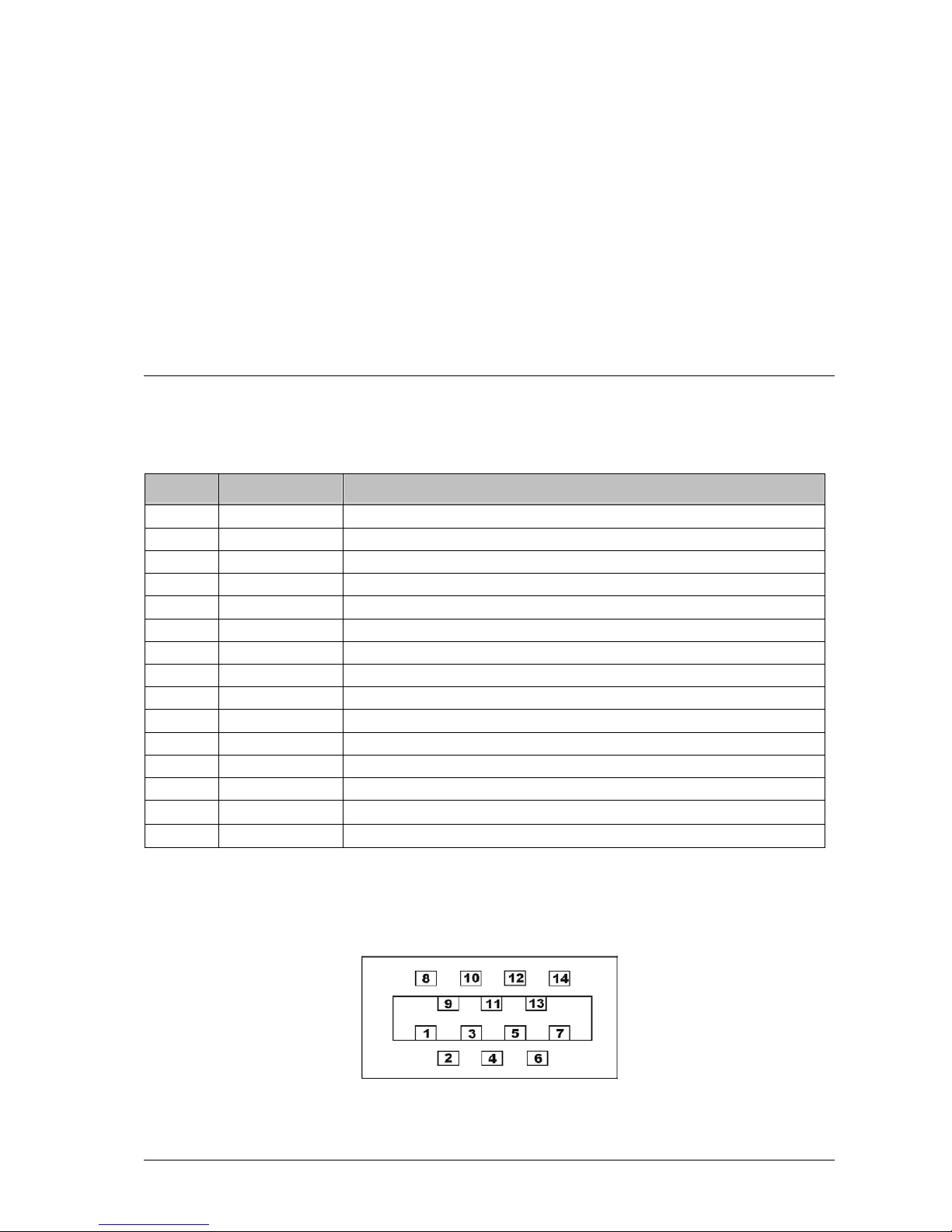
Pin Assignment
Pin Nr. Signal Name Description
1 GND camera ground
2 GND IO I/O signal ground
3 RS232 TX / IN3 reserved
4 ENC A+ encoder Track1 RS422 none reversible input (A+ )
5 ENC B+ encoder Track2 RS422 none reversible input (B+ )
6 IN1 optoisolated Input1*
7 IN2 optoisolated Input2*
8 VCC IN camera supply voltage (7-24V DC)
9 VCC IO supply voltage for optoisolated I/O (5-24V DC)
10 RS232 RX / OUT3 reserved
11 ENC A- encoder Track1 RS422 reversible input (A- )
12 ENC B- encoder Track2 RS422 reversible input (B- )
13 OUT1 optoisolated Output1
14 OUT2 optoisolated Output2
Shield SCHIRM is connected to camera case
*a series resistor 3.6k is required for operation with 24V signals (included in the external
I/O-Panel)
I/O Connector Pin Assignment (View from solder side of connector)

40 • I/O Interface C3 Camera Hardware Reference Manual Rev. 1.3.7
Part Numbers for I/O Connector MDR 14
Description Part Number 3M
14-pin Connector 10114-3000VE
lockable connector case 10314-52F0-008
The internal DIP-Switches
Firmware Version 4.2 does not support the direct calculation of line position with COG algorithm.
Description of LEDs
LED Description
1 (red) on = power supply good
2 (green) on = camera sequencer is active
off = camera sequencer is inactive, e.g. it is waiting for external trigger signal.
3 (green) on = camera start up completed.
DIP-Switch
1 2 3 4 5 6 7 8
Boot Firmware
Version
Baudrate Prom-Nr.
off on off off on on on on 4.8 115k 0
off on off off on off on on 4.7 9.6k 1
off on off off on on off on 4.4 115k 2
on on off off on off off on 4.2 115k 3
off on off off off off off on 4.8 115k 0 (default)

C3 Camera Hardware Reference Manual Rev. 1.3.7 I/O Interface • 41
The External I/O Panel
The optoisolated inputs of the I/O panel, which are provided with a series resistance, can be operated
directly with 24 V DC. In order to use input signals with 5V level, the jumpers JP2 and JP3 on the
panel must be set.
I/O Panel Clamp Connection
Clamp Pin
Nr.
Signal
Name
Description
P1 / 1 SCHIRM camera shield
P1 / 2 GND camera ground
P1 / 3 VCC IN camera supply voltage (7-24V DC)
P2 / 1 ENC B- encoder Track2 RS422 reversible input (B- )
P2 / 2 ENC B+ encoder Track2 RS422 none reversible input (B+ )
P2 / 3 ENC A- encoder Track1 RS422 reversible input (A- )
P2 / 4 ENC A+ encoder Track1 RS422 none reversible input (A+ )
P2 / 5 GND encoder ground is connected to camera ground
P4 / 1 TX / IN3 reserved
P4 / 2 RX / Out3 reserved
P4 / 3 IN1 optoisolated Input1
P4 / 4 IN2 optoisolated Input2
P4 / 5 OUT1 optoisolated Output1
P4 / 6 OUT2 optoisolated Output2
P4 / 7 GND IO I/O signal ground
P4 / 8 VCC IO supply voltage for the optoisolated inputs and outputs (5-24V DC)
P1/1
P2/1
P4/1
42 • The CameraLink Interface of C3 Camera C3 Camera Hardware Reference Manual Rev. 1.3.7
The CameraLink Interface of C3
Camera
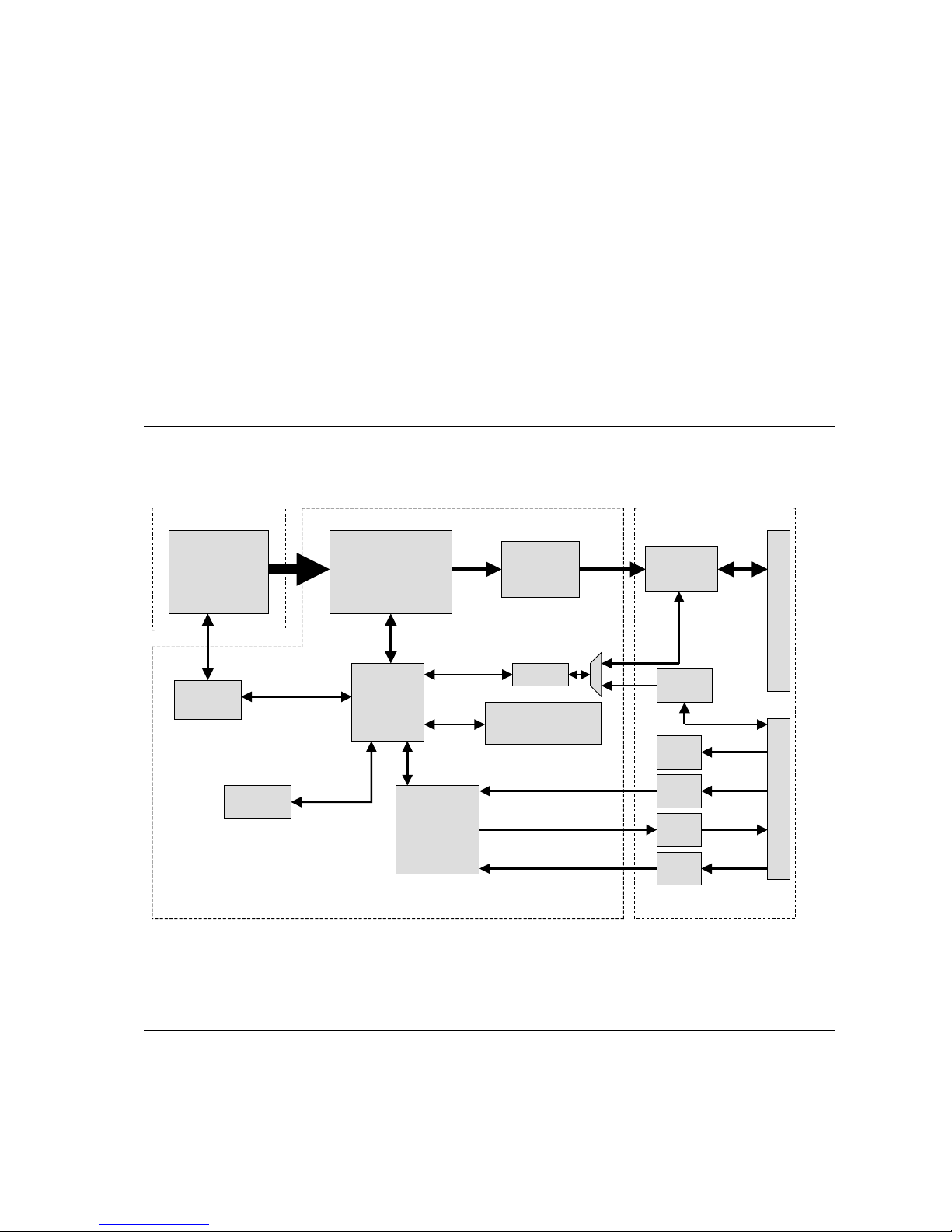
System Overview
Supported CameraLink Modes
A CameraLink compatible frame grabber with at least one Base CameraLink connection is required in
order to operate the C3-Camera with CameraLink interface. The CameraLink pixel frequency of the
Parameter
EE-Prom
CMOS
Sensor
Sensor
Sequencer
Parallel Image
Data Processor
with Image Memory
Camera
Controller
CameraLink
Controller
I/0 Interface
Trigger /
Synchronization
Controller
UART
User Programmable
Register
Table
CameraLink
Interface
Opto In
2x
Opto Out
2x
RS 422
Resolver
Interface
Sensor Board
RS232
Interface
Data Processing Board IO Board
MDR26 CameraLink Connector MDR 14 I/O Connector
Power
Supply

C3 Camera Hardware Reference Manual Rev. 1.3.7 The CameraLink Interface of C3 Camera • 43
camera is factory preset to 40MHz (C3-2350-CL 50MHz). Camera versions with different CameraLink
pixel frequency are available on request. In all versions the frame grabber must support the
corresponding pixel frequency of the camera.
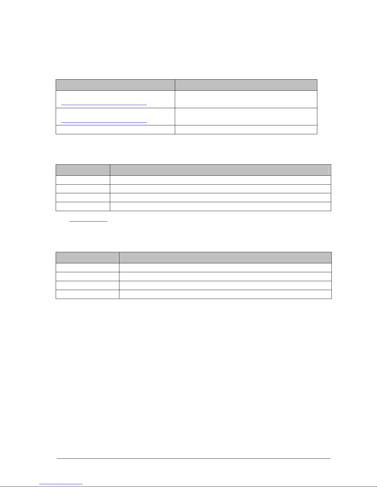
The following frame grabbers have been tested with the C3 camera.
Frame
Grabber
Manufacturer Remarks
MeteorII-CL Matrox Imaging maximum pixel frequency: 50MHz
access of UART functions is possible only over the MIL library.
PcCamLink Dalsa maximum pixel frequency: 62.5MHz
UART interface as standard PC serial port (COM X) is available
Pc2CamLink Dalsa without On-Board memory !
UART interface as standard PC serial port (COM X) is available
X64CL
X64CL-Ipro/Lite
X64CL-Express
X64-Xcelera-CL
Dalsa
maximum pixel frequency: 85MHz
UART interface as standard PC serial port (COM X) is available
X64CL-Ipro/Lite
X64CL-Express
Dalsa
maximum pixel frequency: 85MHz
UART interface as standard PC serial port (COM X) is available
GrabLink Value
Euresys
UART interface as standard PC serial port (COM X) is available
GrabLink
Expert2
Euresys
frame grabber for asynchronous operation of two cameras.
UART interface as standard PC serial port (COM X) is available
PCI-1428
National
Instruments
access of UART functions is possible only over clserial or NI-
IMAQ functions. The 115200 baud mode is not supported by
the board.
Configuration files for the above listed frame grabbers are available.
44 • The CameraLink Interface of C3 Camera C3 Camera Hardware Reference Manual Rev. 1.3.7
Output Modes of C3 Camera with CameraLink Interface
DC Mode Assignment of CameraLink Ports A, B, C
8 bit mode with 2 taps
(always with parallel output of two pixels)
pixel N = port A (7...0)
pixel N+1 = port B (7...0)
12 bit mode with 2 taps
(always with parallel output of two pixels
)
pixel N = port B (3..0) + port A (7..0)
pixel N+1 = port B (7..4) + port C (7..0)
16 bit mode with 1 tap pixel N = port B (7..0) + port A (7..0)
CameraLink Signal Assignment
Signal Name Description
FEN FieldEnable : 1 = frame enabled, 0 = disabled, rising edge indicates the frame beginning
LEN LineEnable : 1 = row enabled, 0 = disabled, rising edge indicates row beginning
DVAL DataEnable : 1 = pixel data enabled, 0 = disabled
SPVAL reserved, always 0
See CL_CFG_REG for additional timing – configuration of CameraLink interface.
Camera Control Signal Assignment
Signal Function
Camera Control 1 (CC1) external trigger input for frame and 3D profile acquisition
Camera Control 2 (CC2) Start-Input for frame sequencer
Camera Control 3 (CC3) Stop-Input for frame sequencer
Camera Control 4 (CC4) Trigger enable signal

C3 Camera Hardware Reference Manual Rev. 1.3.7 The CameraLink Interface of C3 Camera • 45
The UART Configuration Protocol
Apart from the image data transmission line, an additional serial UART channel is available for the
communication with the C3 CameraLink version. This can be implemented by using the hardware
integrated CameraLink UART interface or the separate RS232 lines in the I/O panel. A specific serial
protocol is defined for the access to camera registers, sensor DAC and configuration EEPROM. As a
rule one byte is used for addressing and two bytes for data. An additional command byte in the
beginning of the data block defines the access mode. The following command and error codes are
defined:
Error codes of UART protocol Name Code
Data transmission and command is successfully finished CMD_ACK 80H
Data transmission or command has caused an error CMD_NAK 7FH
Command codes of UART protocol Name Code
write into the sensor DAC CMD_WRITE_DAC 01H
write into a register CMD_WRITE_REG 02H
read from a register CMD_READ_REG 04H
execute a PROM command CMD_PROM 08H
execute a NOP command (to resynchronise the protocol in an error case) CMD_UNKNOWN 80H
After the execution of a command, the camera returns an acknowledgment byte (CMD_ACK,
CMD_NAK) at the end of the data block.
CMD_WRITE_DAC
Byte Description
TX 1 CMD_WRITE_DAC (01H)
TX 2-3 16 bit data word (first high byte, then low byte)
RX 1-2 16 bit data word (first high byte, then low byte), includes the last output word to DAC
RX 3 CMD_ACK / CMD_NAK
CMD_WRITE_REG
Byte Description
TX 1 CMD_WRITE_REG (02H)
TX 2 register address (0-64)
TX 3-4 16 bit data word (first high byte, then low byte), new register contents
RX 1 CMD_ACK / CMD_NAK

46 • The CameraLink Interface of C3 Camera C3 Camera Hardware Reference Manual Rev. 1.3.7
CMD_READ_REG
Byte Description
TX 1 CMD_READ_REG (04H)
TX 2 register address (0-64)
RX 1-2 16 bit data word (first high byte, then low byte), current contents of register
RX 3 CMD_ACK / CMD_NAK
CMD_PROM
Byte Description
TX 1 CMD_PROM (08H)
TX 2 PROM operation code + Address
PROM_OPCODE_WR (40H) + Address (bit 5-0) : write PROM
PROM_OPCODE_RD (80H) + Address (bit 5-0) : read PROM
PROM_OPCODE_EWEN (30H) : enable write
PROM_OPCODE_EWDS (00H) : disable write
TX 3-4 16 bit data word (16 bit)
RX 1-2 16 bit data word (first high byte, then low byte)
RX 3 CMD_ACK / CMD_NAK

C3 Camera Hardware Reference Manual Rev. 1.3.7 The CameraLink Interface of C3 Camera • 47
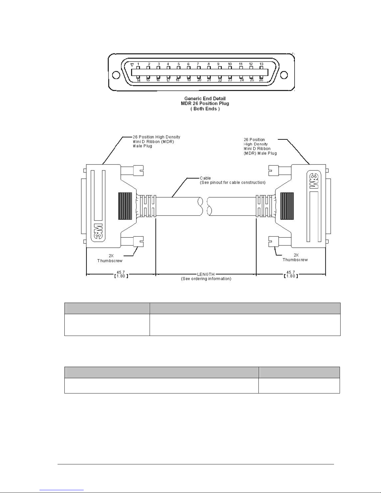
The CameraLink Connection
The signal ground (GND) is connected with the CameraLink inner shield in the camera over a 0 Ohm
jumper, which can be removed if required.
CameraLink Cable Assignment
Camera
Connector Pin
Nr.
Frame Grabber
Pin Nr.
CameraLink Signal Name
1 1 inner shield
14 14 inner shield
2 25 X0-
15 12 X0+
3 24 X1-
16 11 X1+
4 23 X2-
17 10 X2+
5 22 Xclk-
18 9 Xclk+
6 21 X3-
19 8 X3+
7 20 SerTC+
20 7 SerTC-
8 19 SerTFG-
21 6 SerTFG+
9 18 CC1-
22 5 CC1+
10 17 CC2+
23 4 CC2-
11 16 CC3-
24 3 CC3+
12 15 CC4+
25 2 CC4-
13 13 inner shield
26 26 inner shield
SCHIRM SCHIRM is connected to the camera case
48 • The CameraLink Interface of C3 Camera C3 Camera Hardware Reference Manual Rev. 1.3.7
CameraLink Connector (Front View)
CameraLink Cable
3M Part Number for CameraLink Cable
Description Part Number 3M
CameraLink cable (0.5m – 10m) 14T26-SZLB-XXX-0LC wobei XXX:
050 = 0.5 m, 100 = 1 m, 150 =1.5 m, 200 = 2 m, 250 = 2.5 m, 300 = 3 m, 350 = 3.5m,
450 = 4.5 m, 500 = 5 m, 600 = 6 m, 700 = 7 m, 800 = 8m, 900 = 9m, A00 = 10 m
Helukabel Part Number of dragchain cable
Bezeichnung Helukabel Part Number
shielded dragchain cable Supertronic-C-PVC (14 x 0,14mm²) with diameter 7mm
and bending radius 70mm
49627

C3 Camera Hardware Reference Manual Rev. 1.3.7 Technical Specifications • 49
Technical Specifications
C3-1280-CL Sensor
Parameters Specifications
Sensitivity at peak response 1600 LSB / lux s @ 550 nm
corresponds to 10695 LSB / µJ / cm²
Resolution 1280 x 1024
Pixel Size 12µm x 12µm
Sensor Size 15.4mm x 12.3mm, diagonal: 19.7mm
Optics 1 inch (C-Mount)
Sensor ADC Resolution 10 bit
Sensor Dynamic Range 59dB
Max. Internal Full-Frame Rate 450fps
Max. External Full-Frame Rate 61fps (40MHz-CameraLink, 2Tap-Mode)
91fps (60MHz-CameraLink, 2Tap-Mode)
Max. Internal Row Frequency at
1280 Pixels/Row
139kHz
Max. Profile Rate at Max. Row
Length = Max. Internal Row
Frequency / Number of Rows
28800 Hz (16 rows)
14400 Hz (32 rows)
7200 Hz (64 rows)
3600 kHz (128 rows)
1800 Hz (256 rows)
900 Hz (512 rows)
450 Hz (1024 rows)

50 • Technical Specifications C3 Camera Hardware Reference Manual Rev. 1.3.7
Spectral sensitivity of C3-1280-CL sensor

C3 Camera Hardware Reference Manual Rev. 1.3.7 Technical Specifications • 51
C3-2350-CL Sensor
Parameters Specifications
Sensitivity at peak response 2500 LSB / lux s @ 610 nm
Resolution 2352 x 1728
Pixel Size 7µm x 7µm
Sensor Size 16.46mm x 12.10mm, diagonal: 20.43mm
Optics 1” C-Mount and F-Mount
Sensor ADC Resolution 10 bit
Sensor Dynamic Range 59dB
Max. Internal Full-Frame Rate 190fps
Max. External Full-Frame Rate 20fps (40MHz-CameraLink, 2Tap-Mode)
30fps (60MHz-CameraLink, 2Tap-Mode)
Max. Internal Row Frequency at
2352 Pixels/Row
115kHz
Max. Profile Rate at Max. Row
Length = Max. Internal Row
Frequency / Number of Rows
23450 Hz (14 rows)
12160 Hz (27 rows)
3040 Hz (108 rows)
1520 Hz (216 rows)
760 Hz (432 rows)
380 Hz (864 rows)
190 Hz (1728 rows)

52 • Technical Specifications C3 Camera Hardware Reference Manual Rev. 1.3.7
Spectral sensitivity of C3-2350-CL sensor

C3 Camera Hardware Reference Manual Rev. 1.3.7 Technical Specifications • 53
Operating Specifications
Camera Specifications
Parameters C3-1280-CL / C3-2350-CL
Supply Voltage VCC IN 7V – 24V
Power Consumption VCC IN 4W
Operating Temperature 0°C – 50°C
CameraLink –UART
configuration interface
9600 baud or 115200 (default) baud (DIP-
switch) 1 Startbit, 1 Stopbit, no parity
Dimensions see mechanical specifications
Mass 350g
Electrical Specification of I/O Signals
Parameters Specifications
I/O Supply Voltage VCC I/O 5V – 24V DC
VOL, optoisolated outputs, logic ‚0’ Voltage 0.5V
VOH, optoisolated outputs, logic ‚1’ Voltage OC output with 4.7kOhm pull-up
to VCC I/O
VIL, optoisolated inputs, logic ‚0’ Voltage < 2.5V
VIH, optoisolated inputs, logic ‚1’ Voltage > 3.5V
IOH, optoisolated outputs, logic ‚1’ output current OC output with 4.7kOhm pull-up
to VCC I/O
IOL, optoisolated outputs, logic ‚0’ output current 8mA
Encoder interface ENC_A, ENC_B RS422 Standard with 100 Ohm
termination

54 • Technical Specifications C3 Camera Hardware Reference Manual Rev. 1.3.7
Mechanical Specifications
All units are in mm.
C3-1280-CL & C3-2350-CL
(C-Mount)
Hole mounting pattern is identical in all 4 sides
C3-1280-CL & C3-2350-CL
(F-Mount)
Hole mounting pattern is identical in all 4 sides
F-Mount
Bajonett

C3 Camera Hardware Reference Manual Rev. 1.3.7 Service Information • 55
Service Information
Document Revision
Product Information and Updates
Updates
www.AutomationTechnology.de
Service and Support
service@AutomationTechnology.de
In order to process your support inquiries immediately, we always need the serial number of the
camera, a dump of configuration EEPROMs, a snapshot and a precise problem description.
Product Inquiries and Price Quotations
info@AutomationTechnology.de
Rev. Nr. Date Modification
1.0 25.08.2003 Version for C3-A1024-CL, C3-1280-CL
1.1 29.04.2004 Modification of output channel configuration added
1.3.1 01.02.2005 Added changes of Firmware version 3.5
1.3.2 21.03.2007 Update (direct COG height calculation, Laser Register, operating and
mechanical specifications, USB2.0 version removed)
1.3.3 13.02.2008 Update (added C3-2350-CL)
1.3.4 29.05.2008 Update (added new registers for 3D validation, digital output of OVR flag,
Correct Sensor Eclipse)
1.3.5 26.11.08 Update (added new features of Rev. 4.8)
1.3.6 26.05.09 Update (minor corrections)
1.3.7 11.08.09 Update (C3-A1024-CL removed, drawing of camera housing with C-Mount
modified)

56 • Service Information C3 Camera Hardware Reference Manual Rev. 1.3.7
Warranty Conditions
Only the manufacturer can recognize the conditions of warranty. Should other parties than the
manufacturer be responsible for the malfunctioning, we consider the right of warranty as void. This is
the case if the unit is modified electrically or mechanically, particularly in its wiring/soldering, or if the
unit is used for purposes not intended by the manufacturer, or if the unit's external wiring is faulty, or if
the unit is used under conditions outside those stated in its manual.

C3 Camera Hardware Reference Manual Rev. 1.3.7 Index • 57
Index
C
CameraLink 43
Camera Control Signal 45
CameraLink – Kabel 49
Pixeltakt 44
D
DAC 1280 36
DAC 2350 36
I
I/O – Anschluß 39
I/O – Panel 42
R
Register 20
AOI_DY 35
AOI_TRSH 35
AOI_Y0 34
CFG_REG 20
CL_CFG_ REG 26
CL_DX_REG 22
CL_DY_REG 22
CL_X0_REG 21
CTRL_REG 29
DAC_REG 35
DATAOUT_REG 33
HWINFO_REG 26
IO_REG 33
IRTIME_H_REG 24
IRTIME_L_REG 23
ITIME_H_REG 23
ITIME_L_REG 23
JTAG_REG 22
LASER_CONTROL_REG 36, 37
MUX_FRAME_OUTPUT_TIME_H 32
MUX_FRAME_OUTPUT_TIME_L 31
MUX_REG 30
MUX_TRIG_STATUS 31
NUM_AOIS_REG 27
PTIME_H_REG 24
PTIME_L_REG 24
SENSOR_DX_REG 25
SENSOR_REG 24
SENSOR_X0_REG 25
STATUS_REG 30
TRIG_CNT_REG 26
S
Status
Output 15
T
Trigger
Trigger Enable 14
 Loading...