

Page 1
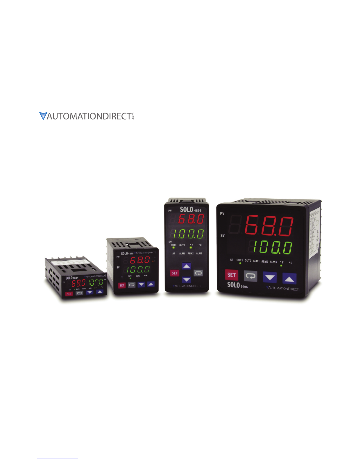
Temperature Controller
Manual Number: SL-USER-M
SOLO
Page 2

Page 3
Please include the Manual Number and the Manual Issue, both shown below, when
communicating with Technical Support regarding this publication.
Manual Number: SL-USER-M
Issue: Rev. C
Issue Date: 07/08
SOLO TEMPERATURE
CONTROLLER
USER MANUAL
Publication History
Issue Date Description of Changes
First Edition 06/07 Original Issue
Rev. A 09/07 Revised parameter ranges, made corrections, added Index
Rev. B 11/07 Revised analog parameters, updated specifications table
Rev. C 07/08 Revised analog parameters, updated specifications table
Page 4

Page 5

WARNING
Thank you for purchasing automation equipment from Automationdirect.com™, doing business as
AutomationDirect. We want your new automation equipment to operate safely. Anyone who installs
or uses this equipment should read this publication (and any other relevant publications) before
installing or operating the equipment.
To minimize the risk of potential safety problems, you should follow all applicable local and national
codes that regulate the installation and operation of your equipment. These codes vary from area to
area and usually change with time. It is your responsibility to determine which codes should be
followed, and to verify that the equipment, installation, and operation is in compliance with the
latest revision of these codes.
At a minimum, you should follow all applicable sections of the National Fire Code, National
Electrical Code, and the codes of the National Electrical Manufacturer's Association (NEMA). There
may be local regulatory or government offices that can also help determine which codes and
standards are necessary for safe installation and operation.
Equipment damage or serious injury to personnel can result from the failure to follow all applicable
codes and standards. We do not guarantee the products described in this publication are suitable for
your particular application, nor do we assume any responsibility for your product design,
installation, or operation.
Our products are not fault-tolerant and are not designed, manufactured or intended for use or resale
as on-line control equipment in hazardous environments requiring fail-safe performance, such as in
the operation of nuclear facilities, aircraft navigation or communication systems, air traffic control,
direct life support machines, or weapons systems, in which the failure of the product could lead
directly to death, personal injury, or severe physical or environmental damage ("High Risk
Activities"). AutomationDirect specifically disclaims any expressed or implied warranty of fitness for
High Risk Activities.
For additional warranty and safety information, see the Terms and Conditions section of our catalog.
If you have any questions concerning the installation or operation of this equipment, or if you need
additional information, please call us at 770-844-4200.
This publication is based on information that was available at the time it was printed. At
AutomationDirect we constantly strive to improve our products and services, so we reserve the right
to make changes to the products and/or publications at any time without notice and without any
obligation. This publication may also discuss features that may not be available in certain revisions of
the product.
Trademarks
This publication may contain references to products produced and/or offered by other companies.
The product and company names may be trademarked and are the sole property of their respective
owners. AutomationDirect disclaims any proprietary interest in the marks and names of others.
Copyright 2007-2008, Automationdirect.com™ Incorporated
All Rights Reserved
No part of this manual shall be copied, reproduced, or transmitted in any way without the prior,
written consent of Automationdirect.com™ Incorporated. AutomationDirect retains the exclusive
rights to all information included in this document.
Page 6

AVERTISSEMENT
Nous vous remercions d'avoir acheté l'équipement d'automatisation de Automationdirect.com™, en
faisant des affaires comme AutomationDirect. Nous tenons à ce que votre nouvel équipement
d'automatisation fonctionne en toute sécurité. Toute personne qui installe ou utilise cet équipement
doit lire la présente publication (et toutes les autres publications pertinentes) avant de l'installer ou
de l'utiliser.
Afin de réduire au minimum le risque d'éventuels problèmes de sécurité, vous devez respecter tous
les codes locaux et nationaux applicables régissant l'installation et le fonctionnement de votre
équipement. Ces codes diffèrent d'une région à l'autre et, habituellement, évoluent au fil du temps. Il
vous incombe de déterminer les codes à respecter et de vous assurer que l'équipement, l'installation
et le fonctionnement sont conformes aux exigences de la version la plus récente de ces codes.
Vous devez, à tout le moins, respecter toutes les sections applicables du Code national de
prévention des incendies, du Code national de l'électricité et des codes de la National Electrical
Manufacturer's Association (NEMA). Des organismes de réglementation ou des services
gouvernementaux locaux peuvent également vous aider à déterminer les codes ainsi que les normes
à respecter pour assurer une installation et un fonctionnement sûrs.
L'omission de respecter la totalité des codes et des normes applicables peut entraîner des dommages
à l'équipement ou causer de graves blessures au personnel. Nous ne garantissons pas que les produits
décrits dans cette publication conviennent à votre application particulière et nous n'assumons aucune
responsabilité à l'égard de la conception, de l'installation ou du fonctionnement de votre produit.
Nos produits ne sont pas insensibles aux défaillances et ne sont ni conçus ni fabriqués pour
l'utilisation ou la revente en tant qu'équipement de commande en ligne dans des environnements
dangereux nécessitant une sécurité absolue, par exemple, l'exploitation d'installations nucléaires, les
systèmes de navigation aérienne ou de communication, le contrôle de la circulation aérienne, les
équipements de survie ou les systèmes d'armes, pour lesquels la défaillance du produit peut
provoquer la mort, des blessures corporelles ou de graves dommages matériels ou
environnementaux («activités à risque élevé»). La société AutomationDirect nie toute garantie
expresse ou implicite d'aptitude à l'emploi en ce qui a trait aux activités à risque élevé.
Pour des renseignements additionnels touchant la garantie et la sécurité, veuillez consulter la section
Modalités et conditions de notre documentation. Si vous avez des questions au sujet de l'installation
ou du fonctionnement de cet équipement, ou encore si vous avez besoin de renseignements
supplémentaires, n'hésitez pas à nous téléphoner au 770-844-4200.
Cette publication s'appuie sur l'information qui était disponible au moment de l'impression. À la
société AutomationDirect, nous nous efforçons constamment d'améliorer nos produits et services.
C'est pourquoi nous nous réservons le droit d'apporter des modifications aux produits ou aux
publications en tout temps, sans préavis ni quelque obligation que ce soit. La présente publication
peut aussi porter sur des caractéristiques susceptibles de ne pas être offertes dans certaines versions
révisées du produit.
Marques de commerce
La présente publication peut contenir des références à des produits fabriqués ou offerts par d'autres
entreprises. Les désignations des produits et des entreprises peuvent être des marques de commerce
et appartiennent exclusivement à leurs propriétaires respectifs. AutomationDirect nie tout intérêt
dans les autres marques et désignations.
Copyright 2007-2008, Automationdirect.com™ Incorporated
Tous droits réservés
Nulle partie de ce manuel ne doit être copiée, reproduite ou transmise de quelque façon que ce soit
sans le consentement préalable écrit de la société Automationdirect.com™ Incorporated.
AutomationDirect conserve les droits exclusifs à l'égard de tous les renseignements contenus dans le
présent document.
Page 7
TABLE OF CONTENTS
Chapter 1: Getting Started
Manual Overview 1–2
SOLO Temperature Controller Introduction 1–3
SOLO Temperature Controller Specifications 1–5
Chapter 2: Installation and Wiring
Ambient Conditions 2–2
Installation Considerations 2–2
Mounting Instructions 2–3
Controller and Panel Cutout Dimensions 2–4
Safety Information 2–6
Terminal Identification 2–8
Chapter 3: Keypad Operation and Setup Parameters
Display, LED and Keypad 3–2
Keypad Operation 3–3
Setup Parameter Listing 3–4
Regulation Mode Parameters 3–7
Operation Mode Parameters 3–15
Initial Setting Parameters 3–17
Reset to Factory Default 3–22
Chapter 4: Controller Inputs and Outputs
Control Input Types 4–2
Event Inputs 4–3
Control Output Types 4–4
Alarm Outputs 4–8
Solo Temperature Controller User Manual
vii
Page 8

Table of Contents
SOLO Temperature Controller User Manual
viii
Chapter 5: Control Modes
PID Control 5–2
On / Off Control 5–3
Ramp / Soak Control 5–4
Manual Control 5–5
Error Display Information 5–5
Chapter 6: Configuration Software
PC Connection 6–2
Software Installation 6–3
Com Port Settings 6–4
Configuration 6–4
Recorder 6–7
Chapter 7: Modbus Communication
Modbus protocol 7–2
Register 7–2
Connection with the DirectLogic PLC 7–7
Connection with the C-more and C-more Micro HMI 7–9
Appendix: Modbus Address Map for Ramp / Soak Control
Last Step Number A–2
Additional Cycles A–2
Next Pattern Number A–2
Ramp / Soak SV A–3
Ramp / Soak Time A–4
Index
Page 9
CHAPTER
CHAPTER
CHAPTER
In This Chapter...
Manual Overview . . . . . . . . . . . . . . . . . . . . . . . . .1–2
SOLO Temperature Controller Introduction . . . . . .1–3
SOLO Temperature Controller Specifications . . . . .1–5
1
1
1
GETTING STARTED
Page 10
Chapter 1: Getting Started
1–2
SOLO Temperature Controller User Manual
Manual Overview
Overview of this Publication
The SOLO Temperature Controller User Manual describes the installation,
configuration, and methods of operation of the SOLO Temperature Controller.
Who Should Read This Manual
This manual contains important information for those who will install, maintain,
and/or operate any of the SOLO Temperature Controllers.
Technical Support
By Telephone: 770-844-4200
(Mon.-Fri., 9:00 a.m.-6:00 p.m. E.T.)
On the Web: support.automationdirect.com
Our technical support group is glad to work with you in answering your questions. If
you cannot find the solution to your particular application, or, if for any reason you
need additional technical assistance, please call technical support at 770-844-4200.
We are available weekdays from 9:00 a.m. to 6:00 p.m. Eastern Time.
We also encourage you to visit our web site where you can find technical and
non-technical information about our products and our company. Visit us at
www.automationdirect.com.
Supplemental Manuals
If you are familiar with industrial control type devices, you may be able to get up
and running with just the aide of the Quick Start Guide that is included with each
SOLO Temperature Controller.
Special Symbols
When you see the “exclamation mark” icon in the left-hand margin, the paragraph to
its immediate right will be a WARNING. This information could prevent injury, loss of
property, or even death (in extreme cases).
When you see the “notepad” icon in the left-hand margin, the paragraph to its
immediate right will be a special note.
Page 11
1–3
SOLO Temperature Controller Introduction
General Description
The SOLO Temperature Controller is a single loop dual output temperature
controller that can control both heating and cooling simultaneously. There are four
types of control modes: PID, ON / OFF, Manual, and Ramp / Soak control.
Depending upon the particular model of controller, the available outputs include
relay, voltage pulse, current, and linear voltage. There are up to three alarm
outputs available to allow seventeen alarm types in the initial setting mode. SOLO
can accept various types of thermocouple, RTD, or analog inputs, and has a built
in RS-485 interface using Modbus slave (ASCII or RTU) communication protocol.
Other features include:
• 1/32, 1/16, 1/8 and 1/4 DIN panel sizes
• 2 line x 4 character 7-segment LED display for Process Value (PV): Red color, and
Set Point (SV): Green color
• Auto Tuning (AT) function with PID control
• Selectable between °C and °F
• 0 to 50 °C (32 to 122 °F) operating temperature range
• UL, CUL and CE agency approvals
• 1-year warranty from date of purchase
Unpacking
After receiving the SOLO Temperature Controller, please check for the following:
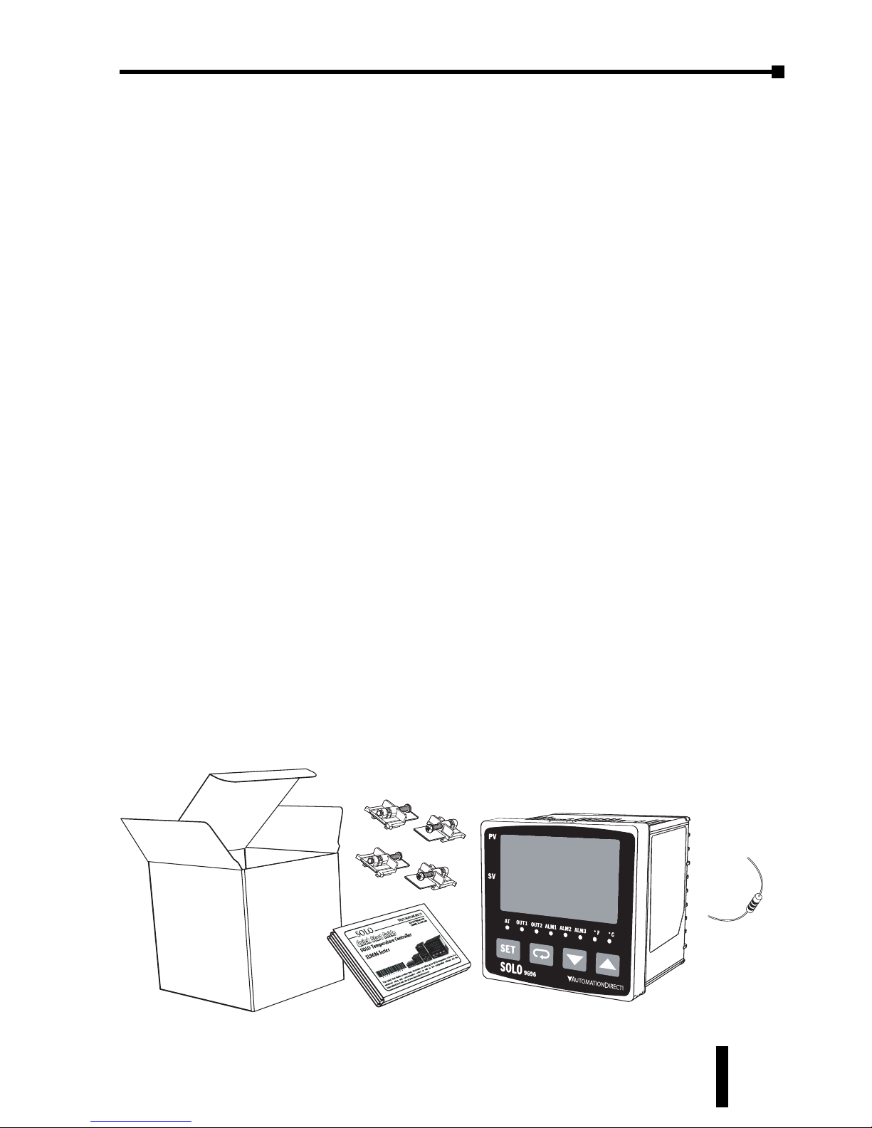
• Make sure that the package includes the Controller, the mounting brackets and
hardware, a 249 ohm resistor and the
Quick Start Guide.
• Inspect the unit to insure it was not damaged during shipment.
• Make sure that the part number indicated on the serial number label corresponds
with the part number of your order.
Box
Quick Start Guide
Mounting Brackets
and Hardware
Temperature Controller
(SL 9696 shown)
249 ohm
resistor
Chapter 1: Getting Started
SOLO Temperature Controller User Manual
1st Ed. Rev C 07/08
Page 12
Chapter 1: Getting Started
1–4
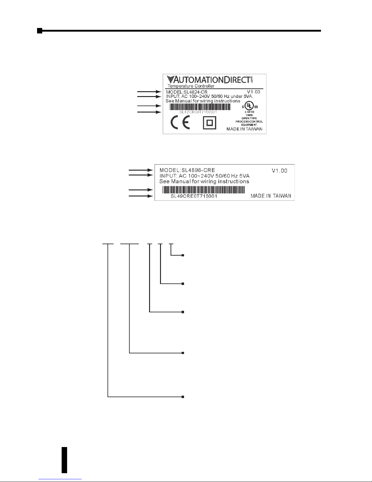
Serial Number Label Information:
SL4824 Series Serial Number Label
SL4848, SL4896, and SL9696 Series Serial Number Label
Model Number Explanation
SL 4896 - V R E
Panel Size (W x H)
4824: 1/32 DIN W48 x H24mm
4848: 1/16 DIN W48 x H48mm
4896: 1/8 DIN W48 x H96mm
9696: 1/4 DIN W96 x H96mm
Solo Temperature Controller
Event Input
None: No Event input
E: Event input is provided
2nd Output Group
R: Relay output
V: Voltage Pulse output
1st Output Group
R: Relay output
V: Voltage Pulse output
C: DC Current output
L: Linear Voltage output
SOLO Model Number
Input Specifications
Bar Code
Serial Number
SOLO Model Number
Input Specifications
Bar Code
Serial Number
SOLO Temperature Controller User Manual
Page 13
1–5
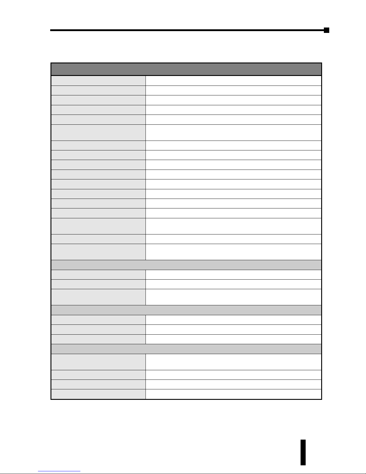
SOLO Temperature Controller Specifications
Specifications
Input Power Requirements
100 to 240 VAC 50 / 60 Hz
Operation Voltage Range
85% to 110% of rated voltage
Power Consumption
5 VA Max
Memory Protection
EEPROM 4K bit, number of writes 100,000
Control Mode
PID, ON/OFF, Ramp / Soak control or Manual
Input Accuracy
Less than ± 0.2% full scale (except thermocouple R, S, & B types)
Max ± 3° (thermocouple R, S, & B types)
Vibration Resistance
10 to 55 Hz, 10 m/s2for 10 min, each in X, Y and Z directions
Shock Resistance
Max. 300 m/s2, 3 times in each 3 axes, 6 directions
Ambient Temperature Range
32°F to 122°F (0°C to 50°C)
Storage Temperature Range
-4°F to 149°F (-20°C to 65°C)
Altitude
2000m or less
Relative Humidity
35% to 80% (non-condensing)
RS-485 Communication
Modbus slave ASCII / RTU protocol
Transmission Speed
2400, 4800, 9600, 19.2K, 38.4K bps
IP Rating
IP65: Complete protection against dust and low pressure spraying water
from all directions. (inside suitable enclosure)
Agency Approvals
UL, CUL, CE (UL file number E311366)
Pollution Degree
Degree 2 - Normally, only non-conductive pollution occurs.
Temporary conductivity caused by condensation is to be expected
Input Types
• Thermocouple
K, J, T, E, N, R, S, B, L, U, TXK
• Platinum RTD
3-wire Pt100, JPt100
• Analog
0-50 mV, 0-5V, 0-10V, 0-20 mA, 4-20 mA
(Current input requires the installation of the supplied 249 ⏲ resistor)
Input Sampling Rates
• Thermocouple
400 ms / per scan
• Platinum RTD
400 ms / per scan
• Analog
150 ms / per scan
Control Output Options
• Relay (R)
SL4824, SL4848: SPST max. resistive load 3A @ 250 VAC
SL4896, SL9696: SPDT max. resistive load 5A @ 250 VAC
• Voltage Pulse (V)
DC 14V Max, output current 40mA Max
• Current (C)
DC 4-20 mA output (Load resistance: Max 600 )
• Linear Voltage (L)
DC 0-10V (Load resistance Min 1K )
Chapter 1: Getting Started
SOLO Temperature Controller User Manual
1st Ed. Rev B 11/07
Page 14

Page 15
INSTALLATION AND
WIRING
2
CHAPTER
CHAPTER
2
2
CHAPTER
In This Chapter...
Ambient Conditions . . . . . . . . . . . . . . . . . . . . . . .2–2
Installation Considerations . . . . . . . . . . . . . . . . . . .2–2
Mounting Instructions . . . . . . . . . . . . . . . . . . . . . .2–3
Controller and Panel Cutout Dimensions . . . . . . . .2–4
Safety Information . . . . . . . . . . . . . . . . . . . . . . . . .2–6
Terminal Identification . . . . . . . . . . . . . . . . . . . . . .2–8
Page 16
Chapter 2: Installation and Wiring
2–2
SOLO Temperature Controller User Manual
Ambient Conditions
Installation Considerations
Improper installation of the controller will greatly reduce its life. Be sure to
observe the following precautions when selecting a mounting location:
• Do not mount the controller near heat-radiating elements or in direct
sunlight.
• Do not install the controller in a place subjected to high temperature, high
humidity, excessive vibration, corrosive gases or liquids, or airborne dust or
metallic particles.
• Do not restrict the air flow to the vent opening on the controller housing
•
This controller is an open-type unit and must be placed in an enclosure to ensure
proper operation and maintain the IP65 rating.
Warning: Failure to observe these precautions may damage the controller and void
the warranty!
Ambient Conditions
Ambient Temperature Range
32°F to 122°F (0°C to 50°C)
Storage Temperature Range
-4°F to 149°F (-20°C to 65°C)
Relative Humidity
35% to 80% (non-condensing)
Altitude
2000m or lower above sea level,
keep from corrosive gas, liquid and dust
Pollution Degree
Degree 2 - Normally, only non-conductive pollution occurs.
Temporary conductivity caused by condensation is to be expected
Vibration Resistance
10 to 55 Hz, 10 m/s2for 10 min, each in X, Y and Z directions
Shock Resistance
Max. 300 m/s2, 3 times in each 3 axes, 6 directions
IP Rating
IP65: Complete protection against dust and low pressure spraying
water from all directions when mounted in a suitable enclosure.
Page 17
2–3
Mounting Instructions
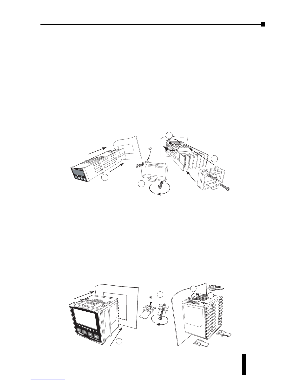
SL4824 Series
Series SL4824 temperature controllers should be mounted through a cutout in an
enclosure or panel by using the dimensions shown on page
The directions for mounting the controller through a cutout are...
1. Insert the temperature controller through the panel cutout.
2. Slide the M3X0.5 nut into the opening in the top of the mounting bracket and
insert the M3X0.5 X 30mm mounting screw in the mounting bracket.
3. Slide the mounting bracket onto the controller and push the mounting bracket
forward until the bracket stops.
4. Tighten the M3X0.5 X 30mm screw to secure temperature controller in place.
SL4848, SL4896, SL9696 Series
Series SL4848, SL4896 and SL9696 temperature controllers should be mounted
through a cutout in an enclosure or panel by using the dimensions shown on page
The directions for mounting the controller through a cutout are...
1. Insert the temperature controller through the panel cutout.
2. Slide the M3X0.5 nut into the opening in the top of the mounting bracket and
insert the M3X0.5 X 30mm mounting screw in the mounting bracket.
3. Insert the mounting bracket into the mounting groove at the top and bottom of
the controller, and push the mounting bracket forward until the bracket stops.
4. Tighten top and bottom screws evenly to secure temperature controller in place.
2
1
3
4
1
2
4
3
Chapter 2: Installation and Wiring
SOLO Temperature Controller User Manual
1st Ed. Rev C 07/08
2–4.
2–4
and 2–5.
Page 18
Chapter 2: Installation and Wiring
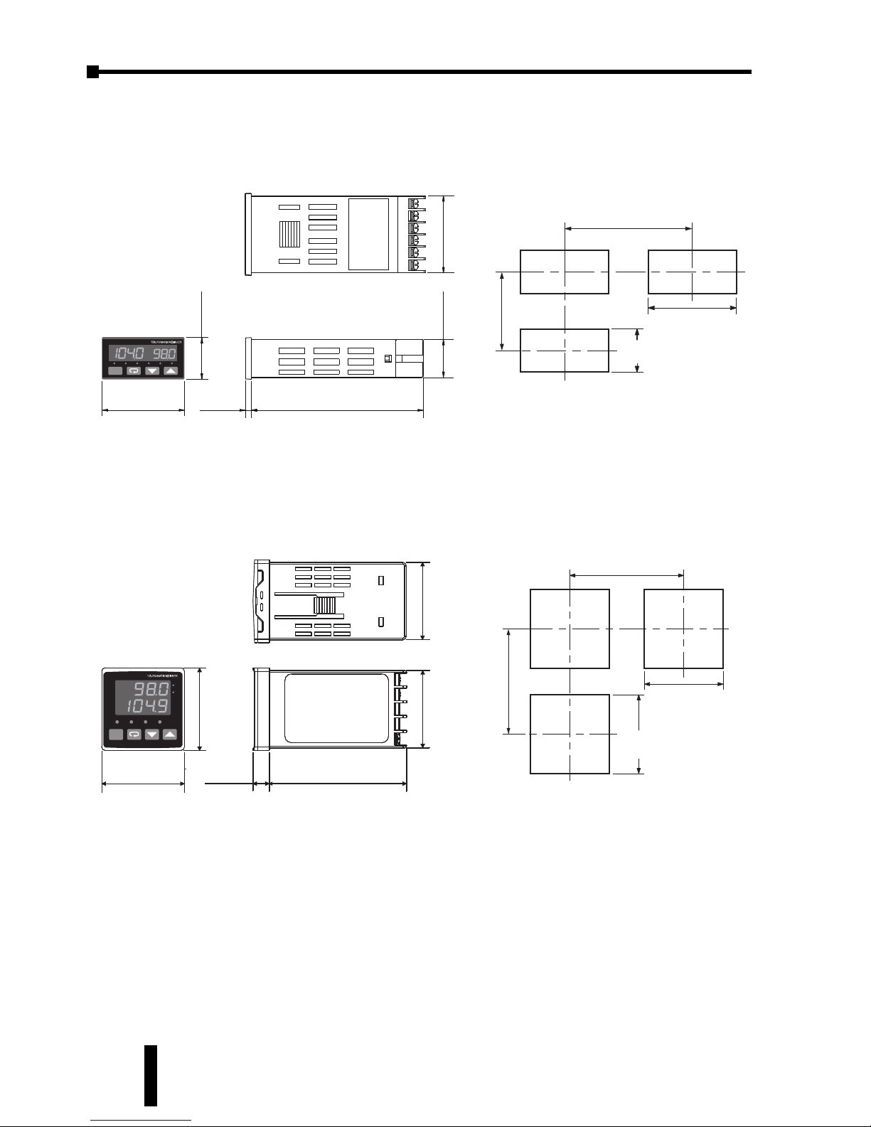
Controller and Panel Cutout Dimensions
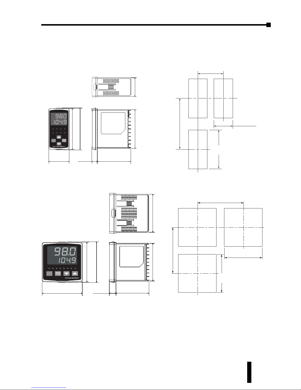
SL4824 Series Minimum Cutout and Spacing
SL4848 Series Minimum Cutout and Spacing
1.76”
(44.75 mm)
3.15”
(80.0 mm)
0.37”
(9.5 mm)
1.89”
(48.0 mm)
1.89”
(48.0 mm)
4848
PV
SOLO
F
C
SV
OUT1
OUT2 ALMAT
SET
1.76”
(44.75 mm)
2.36”
[60.0 mm]
2.56"
[65.0 mm]
1.77"
[45.0 mm]
+0.02
-0
+0.6
-0
1.77"
[45.0 mm]
+0.02
-0
+0.6
-0
(Min.)
(Min.)
0.94”
(24.0 mm)
1.76”
(44.75 mm)
0.86”
(21.85 mm)
3.93”
(99.8 mm)
0.13”
(3.40 mm)
1.89”
(48.0 mm)
PV
SV
AT
OUT1
ALMFCOUT2
SET
4824
SOLO
1.76”
[44.8 mm]
1.58”
[40.0 mm]
0.87"
[22.0 mm]
+0.02
-0
+0.6
-0
+0.02
-0
+0.6
-0
2.56”
[65.0mm]
(Min.)
(Min.)
SOLO Temperature Controller User Manual
Units: inch [mm]
2–4
Page 19
2–5
Controller and Panel Cutout Dimensions, cont.
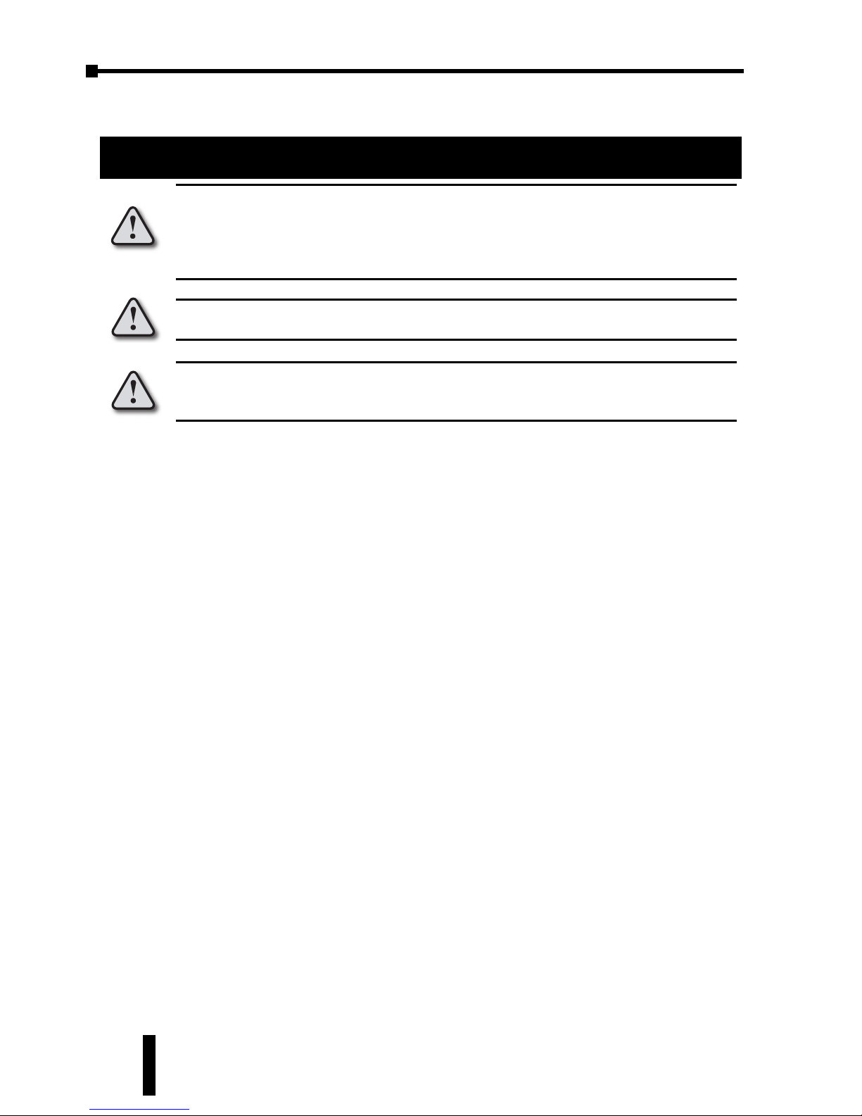
SL4896 Series Minimum Cutout and Spacing
SL9696 Series Minimum Cutout and Spacing
3.57”
(90.8 mm)
3.12”
(79.2 mm)
0.62”
(15.88 mm)
3.86”
(98.0 mm)
3.78”
(96.0 mm)
3.78”
(96.0 mm)
3.57”
(90.8 mm)
9696
PV
SOLO
SV
SET
OUT1
OUT2
ALM1AT
ALM2
ALM3
F
C
4.33"
[110.0 mm]
3.58"
[90.9 mm]
4.33"
[110.0 mm]
(Min)
(Min)
+0.02
-0
+0.6
-0
3.58"
[90.9 mm]
+0.02
-0
+0.6
-0
1.73”
(44.0 mm)
3.58”
(91.0 mm)
3.12”
(79.2 mm)
0.50”
(12.8 mm)
3.87”
(98.2 mm)
3.77”
(95.7 mm)
1.89”
(48.0 mm)
PV
SV
OUT1
OUT2
ALM1AT
SET
ALM2
ALM3
F C
4896
SOLO
2.36"
[60.0 mm]
4.72"
[120.0 mm]
1.75"
[44.5 mm]
+0.02
-0
+0.6
-0
3.60"
[91.4 mm]
+0.02
-0
+0.6
-0
(Min.)
(Min.)
Chapter 2: Installation and Wiring
SOLO Temperature Controller User Manual
1st Ed. Rev C 07/08
Units: inch [mm]
Page 20
Chapter 2: Installation and Wiring
2–6
Safety Information
DANGER!
Wiring Notes: PLEASE READ PRIOR TO INSTALLATION.
Equipment damage or serious injury to personnel can result from the failure to follow all
applicable codes and standards. We do not guarantee the products described in this
publication are suitable for your particular application, nor do we assume any
responsibility for your product design, installation, or operation.
If you have any questions concerning the installation or operation of this equipment, or if
you need additional information, please call us at 1-800-633-0405 or 770-844-4200.
This publication is based on information that was available at the time it was printed. At
Automationdirect.com® we constantly strive to improve our products and services, so we
reserve the right to make changes to the products and/or publications at any time without
notice and without obligation. This publication may also discuss features that may not be
available in certain revisions of the product.
1. Always use recommended solder-less terminals: Fork terminal with isolation (M3 screw,
width is 7.0mm, hole diameter 3.2mm). Screw size: M3 x 6.5 (With 6.8 x 6.8 square
washer). Recommended tightening torque: 0.4 Nm (4kgfcm). Applicable wire:
Solid/twisted wire of 2 mm, 12AWG to 24AWG. Choose AutomationDirect fork
terminals part numbers BM-00120, BM-00220 or BM-00320 depending on wire size.
Be sure to tighten them properly.
2. Protect the controller from dust or foreign objects as they can cause the controller to
malfunction.
3. Never modify or disassemble the controller.
4. Do not connect anything to the “Not used” terminals.
5. Make sure all wires are connected to the correct polarity of terminals.
6. Do not install and/or use the controller in places subject to: (a) Dust or corrosive gases
and liquid. (b) High humidity or high radiation. (c) Vibration or shock. (d) High voltage
or high EMI (e) high temperature.
7. Power must be turned off when wiring or changing a sensor.
WARNING: This controller is an open-type temperature controller. make sure to
evaluate any dangerous application in which a serious human injury or serious
property damage may occur.
WARNING: To prevent electric shock, do not touch the AC terminals while power is
supplied to the controller.
Warning: To minimize the risk of potential safety problems, you should follow all
applicable local and national codes that regulate the installation and operation of
your equipment. These codes vary from area to area and it is your responsibility to
determine which codes should be followed, and to verify that the equipment,
installation, and operation are in compliance with the latest revision of these codes
SOLO Temperature Controller User Manual
Page 21

2–7
Safety Information, cont.
8. Be sure to use wires that match the thermocouple types when extending or connecting
thermocouple wires.
9. Use wires with correct resistance when extending or connecting a RTD.
10. Keep the wire as short as possible when wiring a RTD to the controller and route
power wires as far as possible from sensor wires to prevent interference and induced
noise.
11. This controller is an open-type unit and must be placed in an enclosure to ensure
proper operation and maintain the IP65 rating.
12. Make sure power cables and signals from instruments are all installed properly before
energizing the controller, otherwise serious damage may occur.
13. To prevent electric shock, do not touch the terminals on the controller or try to repair
the controller when power is applied.
14. Do not use acid or alkaline liquids for cleaning. Use a soft, dry cloth to clean the
controller.
15. This instrument is not furnished with a power switch or fuse. Therefore, if a fuse or
power switch is required, install the protection close to the instrument. Recommended
fuse rating: Rated voltage 250 V, Rated current 1 A. Fuse type: Time-delay fuse. See
the AutomationDirect catalog for the appropriate fuse for the specific application.
16. Note: This controller does not provide overcurrent protection. Use of this product
requires that suitable overcurrent protection device(s) must be added to ensure
compliance with all relevant electrical standards and codes. (Rated 250 V, 15 Amps
max). A suitable disconnecting device should be provided near the controller in the
end-use installation.
Chapter 2: Installation and Wiring
SOLO Temperature Controller User Manual
1st Ed. Rev C 07/08
Page 22
Chapter 2: Installation and Wiring
2–8
SOLO Temperature Controller User Manual
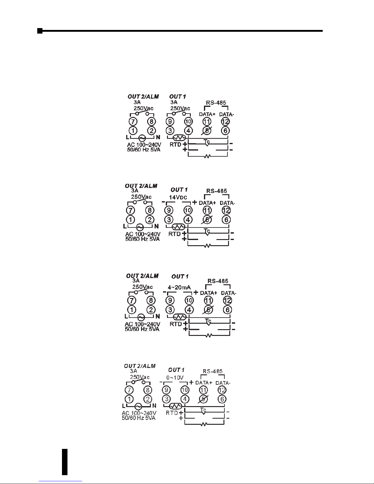
Terminal Identification
SL4824 Series
249 (For IIN only)
V
IN -IIN
249 (For IIN only)
V
IN -IIN
249 (For IIN only)
V
IN -IIN
249 (For IIN only)
V
IN -IIN
SL4824-RR
SL4824-VR
SL4824-CR
SL4824-LR
Page 23
2–9
Chapter 2: Installation and Wiring
SOLO Temperature Controller User Manual
1st Ed. Rev C 07/08
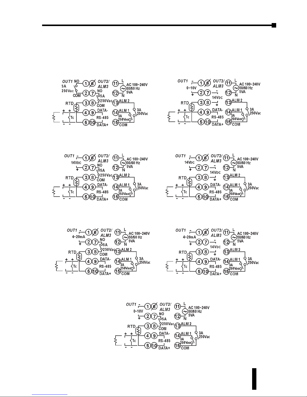
Terminal Identification, cont.
SL4848 Series
249 (For I
IN
only)
V
IN -IIN
249 (For I
IN
only)
V
IN -IIN
249 (For I
IN
only)
V
IN -IIN
249 (For I
IN
only)
V
IN -IIN
249 (For I
IN
only)
V
IN -IIN
249 (For I
IN
only)
V
IN -IIN
249 (For I
IN
only)
V
IN -IIN
SL4848-RR
SL4848-VR
SL4824-CR
SL4848-LR
SL4848-LV
SL4848-VV
SL4848-CV
Page 24
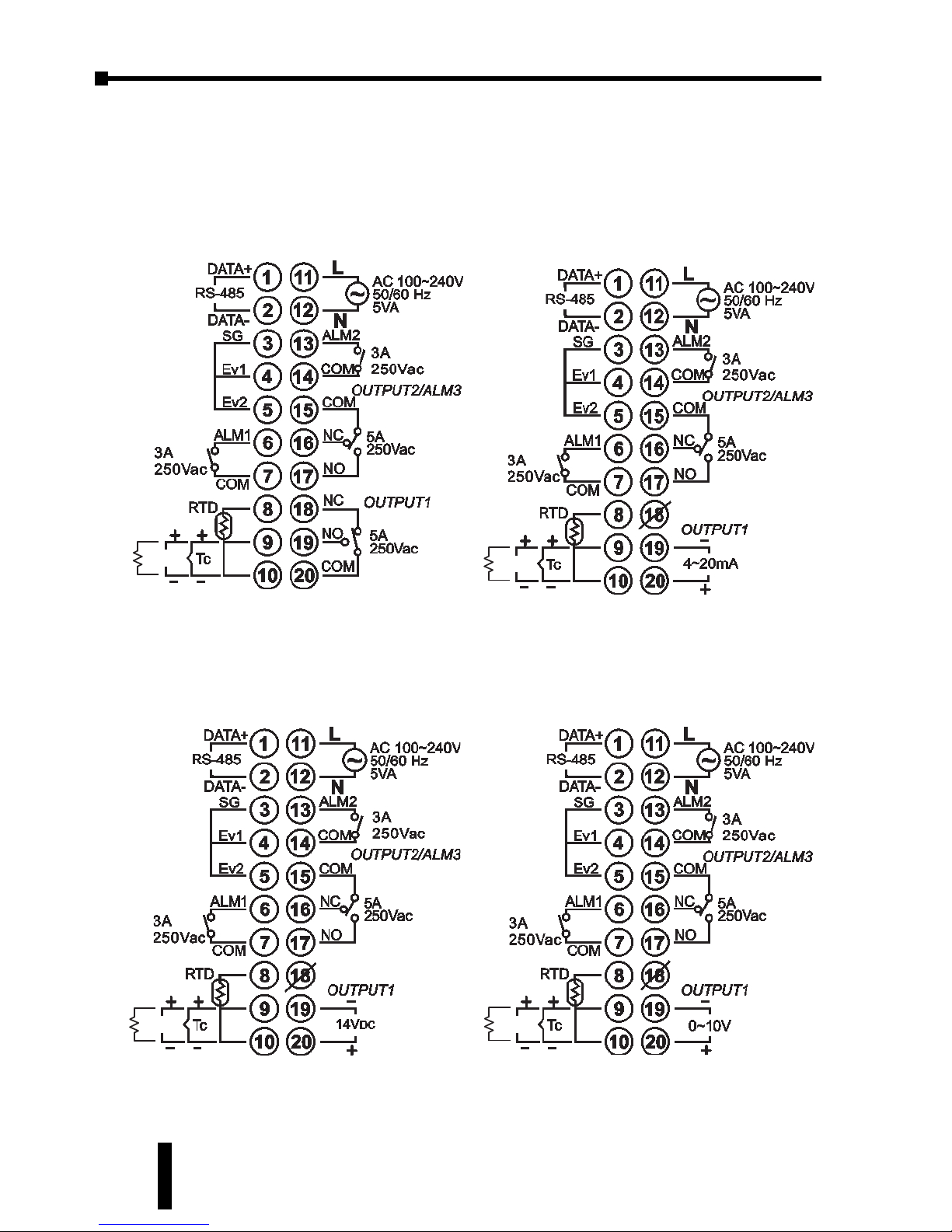
Chapter 2: Installation and Wiring
2–10
Terminal Identification, cont.
SL4896 Series
249 (For I
IN
only)
V
IN -IIN
249 (For I
IN
only)
V
IN -IIN
249 (For I
IN
only)
V
IN -IIN
249 (For I
IN
only)
V
IN -IIN
SOLO Temperature Controller User Manual
SL4896-RRE
SL4896-CRE
SL4896-VRE
SL4896-LRE
Page 25
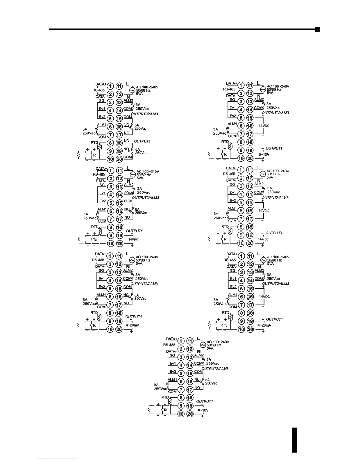
2–11
Terminal Identification, cont.
SL9696 Series
249 (For I
IN
only)
V
IN -IIN
249 (For I
IN
only)
V
IN -IIN
249 (For I
IN
only)
V
IN -IIN
249 (For I
IN
only)
V
IN -IIN
249 (For I
IN
only)
V
IN -IIN
249 (For I
IN
only)
V
IN -IIN
249 (For I
IN
only)
V
IN -IIN
Chapter 2: Installation and Wiring
SOLO Temperature Controller User Manual
1st Ed. Rev C 07/08
SL9696-RRE
SL9696-VRE
SL9696-CRE
SL9696-LRE
SL9696-LVE
SL9696-VVE
SL9696-CVE
Page 26

Page 27
KEYPAD OPERATION
AND
SETUP
PARAMETERS
3
CHAPTER
CHAPTER
3
3
CHAPTER
In This Chapter...
Display, LED and Keypad . . . . . . . . . . . . . . . . . . . .3–2
Keypad Operation . . . . . . . . . . . . . . . . . . . . . . . . .3–3
Setup Parameter Listing . . . . . . . . . . . . . . . . . . . . .3–4
Regulation Mode Parameters . . . . . . . . . . . . . . . . .3–7
Operation Mode Parameters . . . . . . . . . . . . . . . .3–15
Initial Setting Parameters . . . . . . . . . . . . . . . . . . .3–17
Reset to Factory Default . . . . . . . . . . . . . . . . . . . .3–22
Page 28
Chapter 3: Keypad Operation and Setup Parameters
SOLO Temperature Controller User Manual
3–2
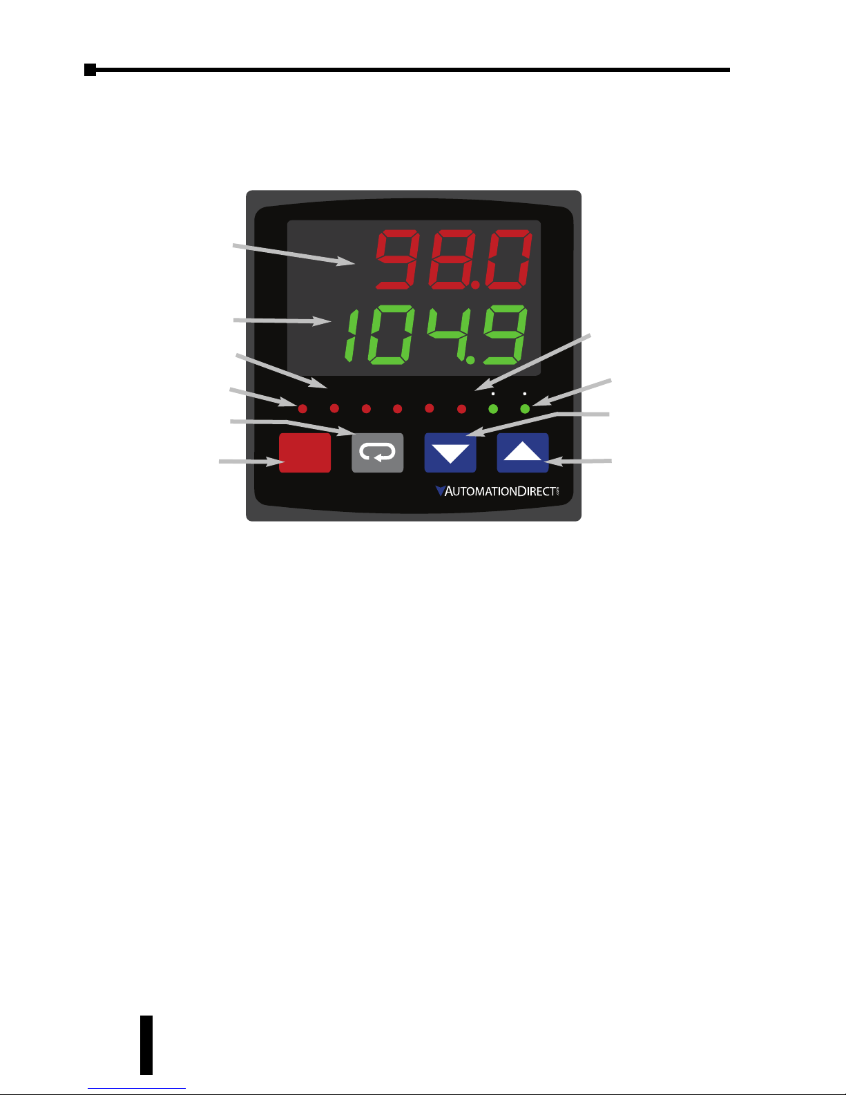
Display, LED and Keypad
The SOLO temperature controller has a two color seven segment LED display, four
types of LED status indicators and four function buttons.
PV Display
The Process Value Display. Displays the value from the input source or the
parameter source.
SV Display
The Set Value Display. Displays the set point of the process, the parameter
operation read value, manipulated variable, or the set value of the parameter.
AT LED Indicator
Auto Tuning LED flashes when the Auto Tuning operation is ON.
OUT1, OUT2 LED Indicators
Output 1 and Output 2 LED indicators light when the output is ON.
°F, °C LED Indicators
Temperature unit LED. °C: Celsius, °F: Fahrenheit
ALM1, ALM2, ALM3 LED Indicators
Alarm output LED indicators light when appropriate alarm is activated. ALM2 and
ALM3 are available on series SL4896 and SL9696 only.
9696
PV
SOLO
SV
SET
OUT1
OUT2
ALM1
AT
ALM2
ALM3
F
C
OUT1, OUT2 LEDs
SV Display
PV Display
ALM1, ALM2,
ALM3, LEDs
°F, °C LEDs
Down Button
SET Button
Up Button
Rotate Button
Auto Tuning LED
Page 29
SOLO Temperature Controller User Manual
3–3
Chapter 3: Keypad Operation and Setup Parameters
1st Ed. Rev C 07/08
Keypad Operation
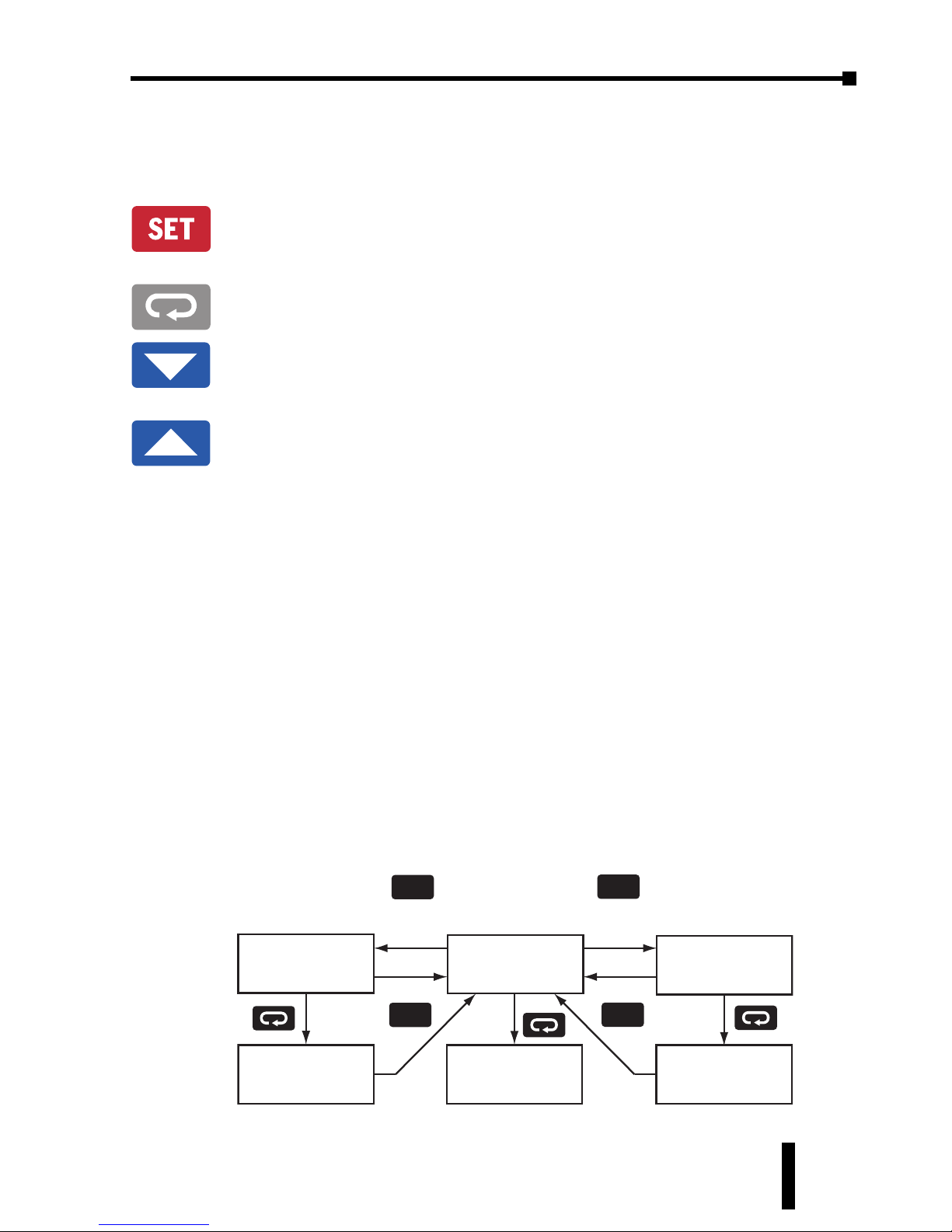
Function Buttons
SET Button
Press the SET button to select the desired function mode and confirm the
setting value.
Rotate Button
Press the Rotate button to select parameters within the function mode.
Down Button
Press the Down button to decrease values displayed on the SV display. Hold
down this button to speed up the decrement.
Up Button
Press the Up button to increase values displayed on the SV display. Hold
down this button to speed up the increment.
Initial Power up
When power is first applied to the temperature controller, the module information
splash screen appears. This screen shows the firmware version on the PV display
and the two output types for that particular model on the SV display. After three
seconds, the controller will automatically proceed to the Operation mode main
screen.
Keypad Operation
The temperature controller has three function modes: Initial Setting mode,
Operation mode and Regulation mode. Press and hold the SET button for three
seconds to go into the Initial Setting mode. Press the SET button for less than three
seconds to access the Regulation mode. Press the Rotate button while inside any
of the three function modes to scroll through the individual parameters for each
function mode. Use the Up and Down buttons to change the individual parameter
values. Pressing the SET button saves the parameter values. Press the SET button
again to return the controller to the Operation mode main screen.
Operation Mode
SET
Hold for 3 sec.
SET
Initial Setting
Mode
Regulation
Mode
SET
Press for less
than 3 sec.
Initial Setting
Parameters
Operation
Parameters
Regulation
Parameters
SET
Page: 3–7
Page: 3–15
Page: 3–17
Page 30
Chapter 3: Keypad Operation and Setup Parameters
SOLO Temperature Controller User Manual
3–4
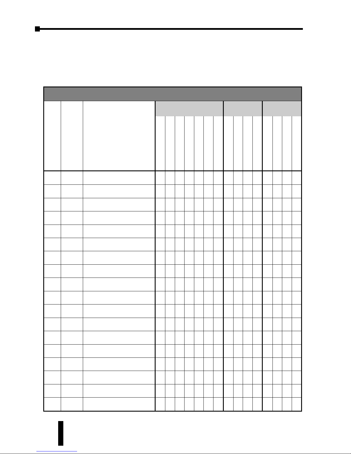
Setup Parameter Listing
Regulation Mode Parameters
Press the
;
button to access these parameters.
Regulation Mode Parameter Availablity
ID #
Displa
y
Parameter Name
Controller Type
Control
Mode
Heating /
Cooling
RR(E)
VR(E)
VV(E)
CR(E)
CV(E)
LR(E)
LV(E)
PID
ON /OFF
Manual
Ramp / Soak
Heating
Cooling
Heating / Cooling
Cooling / Heating
P1-1
At
Auto Tuning
✔ ✔ ✔ ✔ ✔ ✔ ✔ ✔
- - -
✔ ✔ ✔ ✔
P1-2
pid
n
PID Parameter Group
✔ ✔ ✔ ✔ ✔ ✔ ✔ ✔
- -
✔ ✔ ✔ ✔ ✔
P1-3
sv
n
Target SV
✔ ✔ ✔ ✔ ✔ ✔ ✔ ✔
- -
✔ ✔ ✔ ✔ ✔
P1-4
p
n
Proportion Band
✔ ✔ ✔ ✔ ✔ ✔ ✔ ✔
- -
✔ ✔ ✔ ✔ ✔
P1-5
i
n
Integral Time
✔ ✔ ✔ ✔ ✔ ✔ ✔ ✔
- -
✔ ✔ ✔ ✔ ✔
P1-6
d
n
Derivative Time
✔ ✔ ✔ ✔ ✔ ✔ ✔ ✔
- -
✔ ✔ ✔ ✔ ✔
P1-7
PDof
PD Control Offset
✔ ✔ ✔ ✔ ✔ ✔ ✔ ✔
- -
✔ ✔ ✔ ✔ ✔
P1-8
iof
n
Integral Offset
✔ ✔ ✔ ✔ ✔ ✔ ✔ ✔
- -
✔ ✔ ✔ ✔ ✔
P1-9
hts
Heating Hysteresis
✔ ✔ ✔ ✔ ✔ ✔ ✔
-
✔
- -
✔
-
✔ ✔
P1-10
Cts
Cooling Hysteresis
✔ ✔ ✔ ✔ ✔ ✔ ✔
-
✔
- - -
✔ ✔ ✔
P1-11
htpd
Output 1 Heating Period
✔ ✔ ✔ ✔ ✔ ✔ ✔ ✔
-
✔ ✔ ✔
-
✔
-
P1-12
Clpd
Output 1 Cooling Period
✔ ✔ ✔ ✔ ✔ ✔ ✔ ✔
-
✔ ✔
-
✔
-
✔
P1-13
hCpd
Output 2 Period
✔ ✔ ✔ ✔ ✔ ✔ ✔ ✔
-
✔ ✔
- -
✔ ✔
P1-14
Coef
Proportion Band Coefficient
✔ ✔ ✔ ✔ ✔ ✔ ✔ ✔
- -
✔
- -
✔ ✔
P1-15
dead
Dead Band
✔ ✔ ✔ ✔ ✔ ✔ ✔ ✔ ✔
-
✔
- -
✔ ✔
P1-16
tpof
PV Offset
✔ ✔ ✔ ✔ ✔ ✔ ✔ ✔ ✔ ✔ ✔ ✔ ✔ ✔ ✔
P1-17
Crhi
Analog High Adjustment
- - -
✔ ✔ ✔ ✔ ✔ ✔ ✔ ✔ ✔ ✔ ✔ ✔
P1-18
Crlo
Analog Low Adjustment
- - -
✔ ✔ ✔ ✔ ✔ ✔ ✔ ✔ ✔ ✔ ✔ ✔
Page 31
SOLO Temperature Controller User Manual
3–5
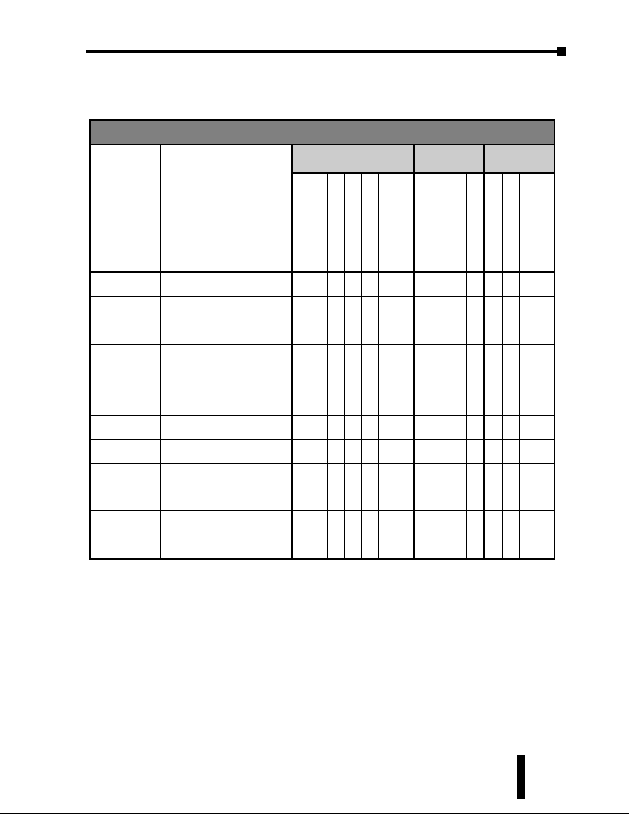
Operation Mode Parameters
Press the
'
button to access these parameters.
Operation Mode Parameter Availablity
ID #
Displa
y
Parameter Name
Controller Type
Control
Mode
Heating /
Cooling
RR(E)
VR(E)
VV(E)
CR(E)
CV(E)
LR(E)
LV(E)
PID
ON /OFF
Manual
Ramp / Soak
Heating
Cooling
Heating / Cooling
Cooling / Heating
P2-1
r-s
Run / Stop
✔ ✔ ✔ ✔ ✔ ✔ ✔ ✔ ✔ ✔ ✔ ✔ ✔ ✔ ✔
P2-2
ptrn
Starting Ramp / Soak Pattern
✔ ✔ ✔ ✔ ✔ ✔ ✔
- - -
✔ ✔ ✔ ✔ ✔
P2-3
sp
Decimal Point Position
✔ ✔ ✔ ✔ ✔ ✔ ✔ ✔ ✔ ✔ ✔ ✔ ✔ ✔ ✔
P2-4
al1h
Alarm 1 High Limit
✔ ✔ ✔ ✔ ✔ ✔ ✔ ✔ ✔ ✔ ✔ ✔ ✔ ✔ ✔
P2-5
al1l
Alarm 1 Low Limit
✔ ✔ ✔ ✔ ✔ ✔ ✔ ✔ ✔ ✔ ✔ ✔ ✔ ✔ ✔
P2-6
al2h
Alarm 2 High Limit
✔ ✔ ✔ ✔ ✔ ✔ ✔ ✔ ✔ ✔ ✔ ✔ ✔ ✔ ✔
P2-7
al2l
Alarm 2 Low Limit
✔ ✔ ✔ ✔ ✔ ✔ ✔ ✔ ✔ ✔ ✔ ✔ ✔ ✔ ✔
P2-8
al3h
Alarm 3 High Limit
✔ ✔ ✔ ✔ ✔ ✔ ✔ ✔ ✔ ✔ ✔ ✔ ✔
- -
P2-9
al3l
Alarm 3 Low Limit
✔ ✔ ✔ ✔ ✔ ✔ ✔ ✔ ✔ ✔ ✔ ✔ ✔
- -
P2-10
loC
Lock Mode
✔ ✔ ✔ ✔ ✔ ✔ ✔ ✔ ✔ ✔ ✔ ✔ ✔ ✔ ✔
P2-11
out1
Output 1 Level
✔ ✔ ✔ ✔ ✔ ✔ ✔ ✔ ✔ ✔ ✔ ✔ ✔ ✔ ✔
P2-12
out2
Output 2 Level
✔ ✔ ✔ ✔ ✔ ✔ ✔ ✔ ✔ ✔ ✔
- -
✔ ✔
Chapter 3: Keypad Operation and Setup Parameters
1st Ed. Rev C 07/08
Page 32
Chapter 3: Keypad Operation and Setup Parameters
SOLO Temperature Controller User Manual
3–6
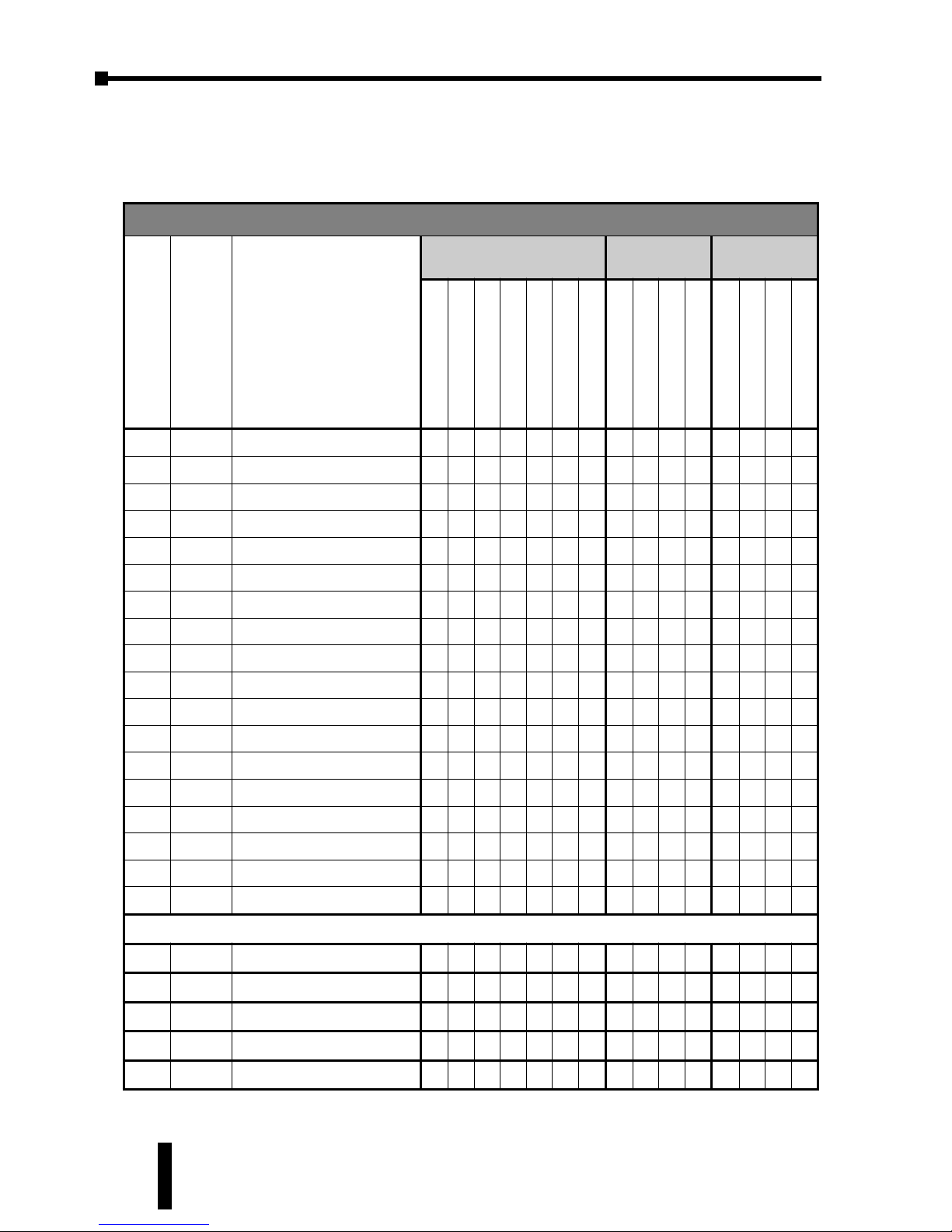
Initial Setting Parameters
Press the
;
button for more than three seconds to access these
parameters.
Initial Setting Mode Parameter Availablity
ID # Display Parameter Name
Controller Type
Control
Mode
Heating /
Cooling
RR(E)
VR(E)
VV(E)
CR(E)
CV(E)
LR(E)
LV(E)
PID
ON /OFF
Manual
Ramp / Soak
Heating
Cooling
Heating / Cooling
Cooling / Heating
P3-1
inpt
Input Type
✔ ✔ ✔ ✔ ✔ ✔ ✔ ✔ ✔ ✔ ✔ ✔ ✔ ✔ ✔
P3-2
tpun
Temperature Unit
✔ ✔ ✔ ✔ ✔ ✔ ✔ ✔ ✔ ✔ ✔ ✔ ✔ ✔ ✔
P3-3
tp-h
Input Range High
✔ ✔ ✔ ✔ ✔ ✔ ✔ ✔ ✔ ✔ ✔ ✔ ✔ ✔ ✔
P3-4
tp-l
Input Range Low
✔ ✔ ✔ ✔ ✔ ✔ ✔ ✔ ✔ ✔ ✔ ✔ ✔ ✔ ✔
P3-5
Ctrl
Control Mode
✔ ✔ ✔ ✔ ✔ ✔ ✔ ✔ ✔ ✔ ✔ ✔ ✔ ✔ ✔
P3-6
Patn
Ramp / Soak Pattern*
✔ ✔ ✔ ✔ ✔ ✔ ✔ ✔ ✔ ✔ ✔ ✔ ✔ ✔ ✔
P3-7
s-hC
Heating / Cooling
✔ ✔ ✔ ✔ ✔ ✔ ✔ ✔ ✔ ✔ ✔ ✔ ✔ ✔ ✔
P3-8
ala1
Alarm 1
✔ ✔ ✔ ✔ ✔ ✔ ✔ ✔ ✔ ✔ ✔ ✔ ✔ ✔ ✔
P3-9
ala2
Alarm 2
✔ ✔ ✔ ✔ ✔ ✔ ✔ ✔ ✔ ✔ ✔ ✔ ✔ ✔ ✔
P3-10
ala3
Alarm 3
✔ ✔ ✔ ✔ ✔ ✔ ✔ ✔ ✔ ✔ ✔ ✔ ✔ ✔ ✔
P3-11
sala
System Alarm
✔ ✔ ✔ ✔ ✔ ✔ ✔ ✔ ✔ ✔ ✔ ✔ ✔ ✔ ✔
P3-12
Cosh
On-Line Configuration
✔ ✔ ✔ ✔ ✔ ✔ ✔ ✔ ✔ ✔ ✔ ✔ ✔ ✔ ✔
P3-13
C-SL
Modbus Protocol
✔ ✔ ✔ ✔ ✔ ✔ ✔ ✔ ✔ ✔ ✔ ✔ ✔ ✔ ✔
P3-14
C-no
Network Address
✔ ✔ ✔ ✔ ✔ ✔ ✔ ✔ ✔ ✔ ✔ ✔ ✔ ✔ ✔
P3-15
bps
Baud Rate
✔ ✔ ✔ ✔ ✔ ✔ ✔ ✔ ✔ ✔ ✔ ✔ ✔ ✔ ✔
P3-16
LEn
Bit Length
✔ ✔ ✔ ✔ ✔ ✔ ✔ ✔ ✔ ✔ ✔ ✔ ✔ ✔ ✔
P3-17
Prty
Parity
✔ ✔ ✔ ✔ ✔ ✔ ✔ ✔ ✔ ✔ ✔ ✔ ✔ ✔ ✔
P3-18
Stop
Stop Bit
✔ ✔ ✔ ✔ ✔ ✔ ✔ ✔ ✔ ✔ ✔ ✔ ✔ ✔ ✔
*Once a Ramp / Soak pattern (P3-6) is selected, the following parameters are available.
P3-19
sp
mn
Ramp / Soak SV
✔ ✔ ✔ ✔ ✔ ✔ ✔
- - -
✔ ✔ ✔ ✔ ✔
P3-20
ti
mn
Ramp / Soak Time
✔ ✔ ✔ ✔ ✔ ✔ ✔
- - -
✔ ✔ ✔ ✔ ✔
P3-21
psx
n
Last Step Number
✔ ✔ ✔ ✔ ✔ ✔ ✔
- - -
✔ ✔ ✔ ✔ ✔
P3-22
CYC
n
Additional Cycles
✔ ✔ ✔ ✔ ✔ ✔ ✔
- - -
✔ ✔ ✔ ✔ ✔
P3-23
lin
n
Next Pattern Number
✔ ✔ ✔ ✔ ✔ ✔ ✔
- - -
✔ ✔ ✔ ✔ ✔
Page 33
SOLO Temperature Controller User Manual
3–7
Regulation Mode Parameters
Press the
;
button to access these parameters.
Range: On - Auto Tuning activated
Off - Auto Tuning deactivated
When this parameter is set to On, the controller begins auto tuning.
After auto tuning is complete, the parameter is set to Off automatically.
If this parameter is set to Off during the auto tuning process, the
controller stops the auto tuning process immediately and does not
change any PID parameter.
This parameter name will be displayed as one of the following.
Range: PID0 to PID4
The SOLO controller can store up to 4 PID parameter groups (
PID0
-
PID3
) for regular operation. The PID Parameter Group parameter sets
which PID group (
PID0- PID3
) to use for control. The SV display
shows the Target SV assigned to the PID group. (For more information
about the Target SV, refer to P1-3 Target SV)
When
PID4
is selected as the PID parameter group, the controller
automatically chooses the one PID parameter group (
PID0- PID3
)
that has a Target SV that is the nearest to the SV set by the operator and
uses that group for control.
PID
is a special PID parameter group for the SL4896 and SL9696
series controllers Event inputs. This is the PID group that the controller
uses when the Event 2 input is on. To configure the PID parameter for
this parameter group, the Event 2 input must be active.
This parameter name will be displayed as one of the following. Only
the Target SV for the selected PID Parameter Group (
PID0
, P1-2) will
be displayed when accessing this parameter.
SV
n
Target SV ID Number P1-3
PID0
PID Parameter Group 0
PID1
PID Parameter Group 1
PID2
PID Parameter Group 2
PID3
PID Parameter Group 3
PID4
PID Parameter Group Auto Select
PID
PID Parameter Group for Event 2 Input
PID
n
PID Parameter Group ID Number P1-2
At
Auto Tuning ID Number P1-1
Chapter 3: Keypad Operation and Setup Parameters
1st Ed. Rev C 07/08
Page 34
Chapter 3: Keypad Operation and Setup Parameters
SOLO Temperature Controller User Manual
3–8
Range: -99.9 to 999.9
(For more information about the parameter groups, refer to P1-2 PID
Parameter Group.)
The Target SV is the setting value that each parameter group works
toward. When the Target SV is the closest to the SV of the PID groups,
this value is used to select which tuning parameters are used by the
controller. The controller can store up to four PID parameter groups
(
PID0
, -
PID3
) for regular operation. One of the PID parameter
groups can be selected manually, or the controller selects the PID
parameter group that has a Target SV that is the nearest to the SV set by
the operator. If there are two or more PID parameter groups that have
SV values equally close to the current PV, the controller uses the
lowest number parameter group (eg. If parameter groups 0 - 3 have the
same Target SV, the controller uses the parameter group 0).
The parameter
SV is the Target SV of the PID parameter group for
Event 2 input. This parameter is only displayed when the Event 2 input
is on. The Event 2 input is only available on the SL4896 and SL9696
series controllers.
This parameter name will be displayed as one of the following. Only
the Proportion Band for the selected PID Parameter Group (
PID0
, P1-
2) will be displayed when accessing this parameter.
Range: 0.1 to 999.9
(For more information about the parameter groups, refer to P1-2 PID
Parameter Group.)
The Proportion Band is a parameter group used for PID control. The
controller can store up to four PID parameter groups (
PID0
, -
PID3
)
for regular operation. One of the PID parameter groups can be selected
manually, or the controller selects the PID parameter group that has a
Target SV that is the nearest to the SV set by the operator.
The parameter
P is the Proportion Band of the PID parameter group for
p0
Proportion Band of PID Parameter Group 0
p1
Proportion Band of PID Parameter Group 1
p2
Proportion Band of PID Parameter Group 2
p3
Proportion Band of PID Parameter Group 3
p
Proportion Band of PID Parameter Group for Event 2 Input
P
n
Proportion Band ID Number P1-4
SV0
Target SV of PID Parameter Group 0
SV1
Target SV of PID Parameter Group 1
SV2
Target SV of PID Parameter Group 2
Sv3
Target SV of PID Parameter Group 3
sv
Target SV of PID Parameter Group for Event 2 Input
Page 35
SOLO Temperature Controller User Manual
3–9
Event 2 input. This parameter is only displayed when the Event 2 input
is on. The Event 2 input is only available on the SL4896 and SL9696
series controllers.
This parameter name will be displayed as one of the following. Only
the Integral Time for the selected PID Parameter Group (
PID0
, P1-2)
will be displayed when accessing this parameter.
Range: 0 to 9999 (Sec)
(For more information about the parameter groups, refer to P1-2 PID
Parameter Group.)
The Integral Time is a parameter group used for PID control. The
controller can store up to four PID parameter groups (
PID0
, -
PID3
)
for regular operation. One of the PID parameter groups can be selected
manually, or the controller selects the PID parameter group that has a
Target SV that is the nearest to the SV set by the operator.
The parameter
i is the Integral Time of the PID parameter group for
Event 2 input. This parameter is only displayed when the Event 2 input
is on. The Event 2 input is only available on the SL4896 and SL9696
series controllers.
This parameter name will be displayed as one of the following. Only
the Derivative Time for the selected PID Parameter Group (
PID0
, P1-2)
will be displayed when accessing this parameter.
Range: 0.1 to 999.9 (Sec)
(For more information about the parameter groups, refer to P1-2 PID
Parameter Group.)
The Derivative Time is a parameter group used for PID control. The
controller can store up to four PID parameter groups (
PID0
, -
PID3
)
for regular operation. One of the PID parameter groups can be selected
d0
Derivative Time of PID Parameter Group 0
d1
Derivative Time of PID Parameter Group 1
d2
Derivative Time of PID Parameter Group 2
d3
Derivative Time of PID Parameter Group 3
d
Derivative Time of PID Parameter Group for Event 2 Input
d
n
Derivative Time ID Number P1-6
i0
Integral Time of PID Parameter Group 0
i1
Integral Time of PID Parameter Group 1
i2
Integral Time of PID Parameter Group 2
i3
Integral Time of PID Parameter Group 3
i
Integral Time of PID Parameter Group for Event 2 Input
I
n
Integral Time ID Number P1-5
Chapter 3: Keypad Operation and Setup Parameters
1st Ed. Rev C 07/08
Page 36
Chapter 3: Keypad Operation and Setup Parameters
SOLO Temperature Controller User Manual
3–10
manually, or the controller selects the PID parameter group that has a
Target SV that is the nearest to the SV set by the operator.
The parameter
d is the Derivative Time of the PID parameter group for
Event 2 input. This parameter is only displayed when the Event 2 input
is on. The Event 2 input is only available on the SL4896 and SL9696
series controllers.
Range: 0.0 to 100.0 (%)
The PD Control Offset parameter is available when the P or PD
control is selected [Integral Time parameter (
I
n, P1-5) is zero].
This parameter defines the offset of the output. When the P or PD
control is used, the control cannot stabilize the PV at the SV because
the output is zero when the PV is equal to the SV. This parameter
modifies the output level when the PV is equal to the SV.
This parameter name will be displayed as one of the following.
Range: 0.0 to 100.0 (%)
(For more information about the parameter groups, refer to PID
Parameter Group, P1-2.)
The Integral Offset parameter is available when the PI or PID control is
selected. [Integral Time parameter (
I
n, P1-5) is not zero.]
The Auto Tuning process will decide the offset value automatically.
If this parameter is not used (
iof
= 0), the output is zero when the PV
is equal to the SV. If the Integral Time parameter (
I
n, P1-5) is used only
to eliminate the steady error, it may take a long time to reach the SV
because it needs time to accumulate the error. In this case, this
parameter is useful. This parameter defines the default output level on
start up. It will inprove the speed that the PV reaches the SV.
The parameter
iof is the Integral Offset of the PID parameter group
for Event 2 input. This parameter is only displayed when the Event 2
input is on. The Event 2 input is only available on the SL4896 and
SL9696 series controllers.
Range: 0.0 to 999.9
hts
Heating Hysteresis ID Number P1-9
iof0
Integral Offset of PID Parameter Group 0
iof1
Integral Offset of PID Parameter Group 1
iof2
Integral Offset of PID Parameter Group 2
iof3
Integral Offset of PID Parameter Group 3
iof
Integral Offset of PID Parameter Group for Event 2 Input
iof
n
Integral Offset ID Number P1-8
pdof
PD Control Offset ID Number P1-7
Page 37
SOLO Temperature Controller User Manual
3–11
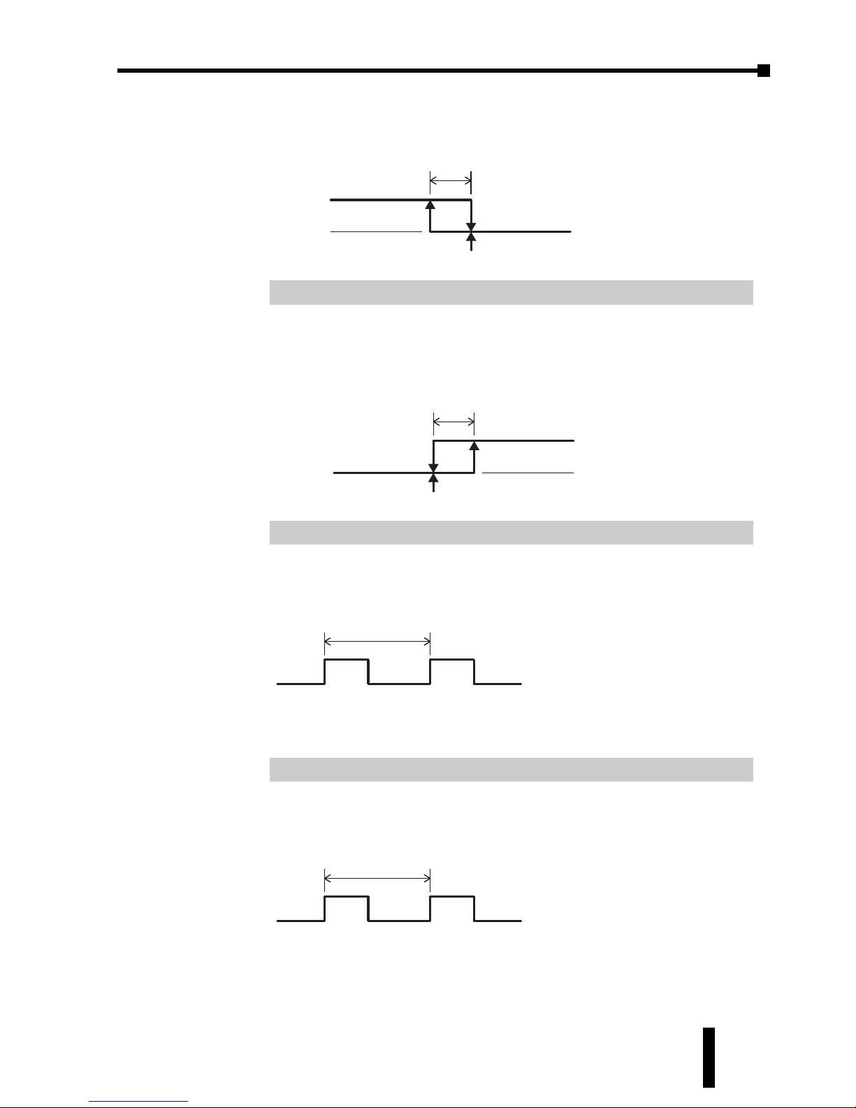
The Heating Hysteresis parameter defines the amount that the PV must
go below the SV before the output turns on. This parameter is available
only for On / Off control with an output programmed for heating.
Range: 0.0 to 999.9
The Cooling Hysteresis parameter defines the amount that the PV must
go above the SV before the output turns on. This parameter is available
only for On / Off control with an output programmed for cooling.
Range: 0.5 to 99 seconds
The Output 1 Heating parameter defines one output period or the
duration of one on / off cycle for Output 1.
This parameter is available when Output 1 is programmed as a heating
output in the PID or Ramp / Soak mode.
Range: 0.5 to 99 seconds
The Output 1 Cooling parameter defines one output period or the
duration of one on / off cycle for Output 1.
This parameter is available when Output 1 is programmed as a cooling
output in the PID or Ramp / Soak mode.
ClPD
Output 1 Cooling Period
Clpd
Output 1 Cooling Period ID Number P1-12
HTPD
Output 1 Heating Period
htpd
Output 1 Heating Period ID Number P1-11
Cts
Cooling Hysteresis
PV
SV
ON
OFF
Output
Cts
Cooling Hysteresis ID Number P1-10
hts
Heating Hysteresis
PV
SV
ON
OFF
Output
Chapter 3: Keypad Operation and Setup Parameters
1st Ed. Rev C 07/08
Page 38
Chapter 3: Keypad Operation and Setup Parameters
SOLO Temperature Controller User Manual
3–12
Range: 0.5 to 99 seconds
The Output 1 Cooling parameter defines one output period or the
duration of one on / off cycle for Output 2.
This parameter is available when Output 2 is programmed as a heating
or cooling output in the PID or Ramp / Soak mode.
Range: 0.01 to 99.99
This Proportion Band Coefficient parameter is available when a dual
output mode (heating and cooling) is selected. This parameter allows
the second output control to have a different proportional setting than
the first output control. The first output control proportional band
setting is multiplied by this parameter to create a proportional band
setting for the second output control.
Range: The range varies according to the Decimal Point Position (
SP
, P2-3).
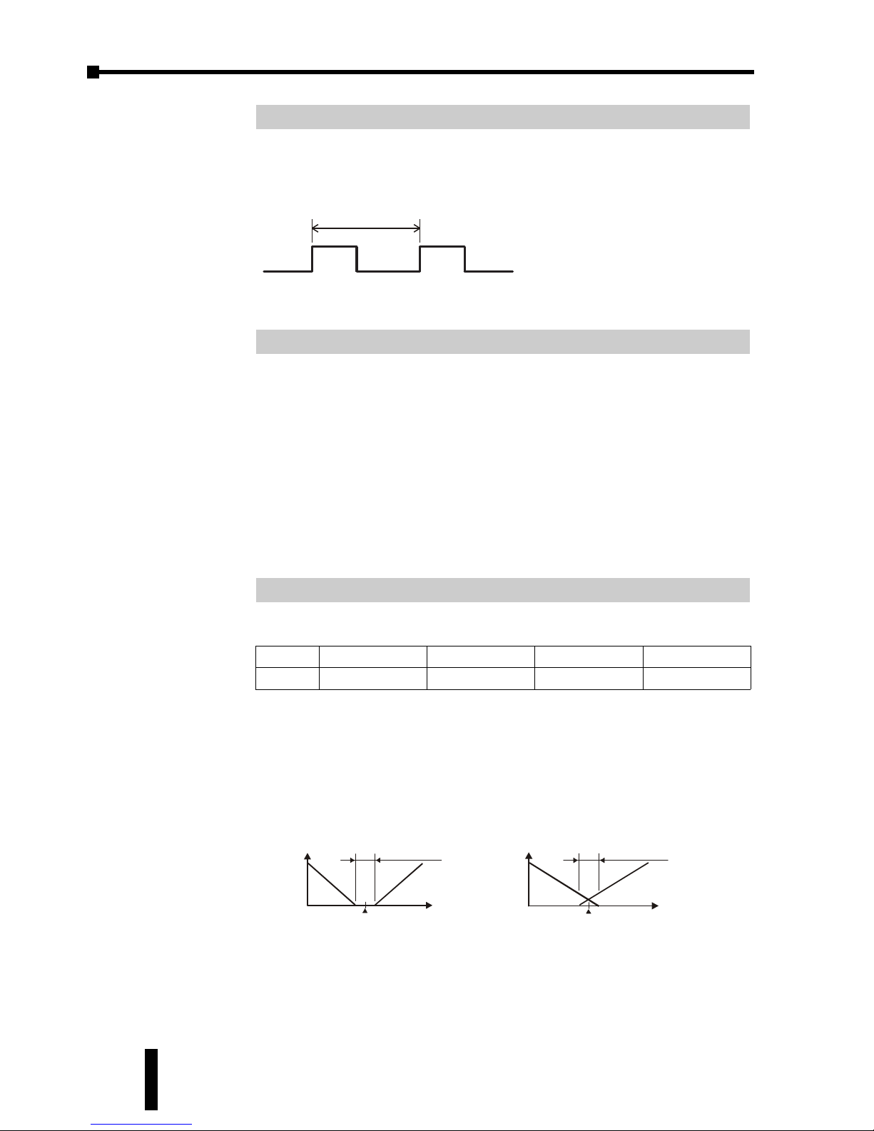
The dead band zone is the area around the SV where the output is not
effected by the proportional control value (PV). For PID control, as
long as the PV remains within the dead band zone, the output is not
affected by the proportional control. The integral and derivative
controls ignore the dead band setting and may cause the output to be
on within the dead band zone.
For On / Off type control the Dead Band parameter defines the area
around the SV where the output remains off. The PV must go beyond
the dead band range in order for either output 1 or output 2 to turn on.
PV
0
Output
Dead band: dead
band width=po sitive
Set point
Heating Cooling
dead
Dual Loop PID control
positive dead band
PV
0
Output
Dead band: dead
band width=ne gative
Set point
Heatin g
Cooling
dead
Dual Loop PID control
negative dead band
sp
0 1 2 3
dead
-99 to 999 -99.9 to 999.9 -9.99 to 99.99 -.999 to 9.999
dead
Dead Band ID Number P1-15
(First Output) Proportion Band * Proportion Band Coefficient = Second Proportional Band
(
P
n
, P1-4) (
Coef
, P1-14)
Coef
Proportion Band Coefficient ID Number P1-14
hCPD
Output 2 Period
HCpd
Output 2 Period ID Number P1-13
Page 39
SOLO Temperature Controller User Manual
3–13
Range: The range varies according to the Decimal Point Position (SP, P2-3).
This parameter is used to add an offset value to the PV.
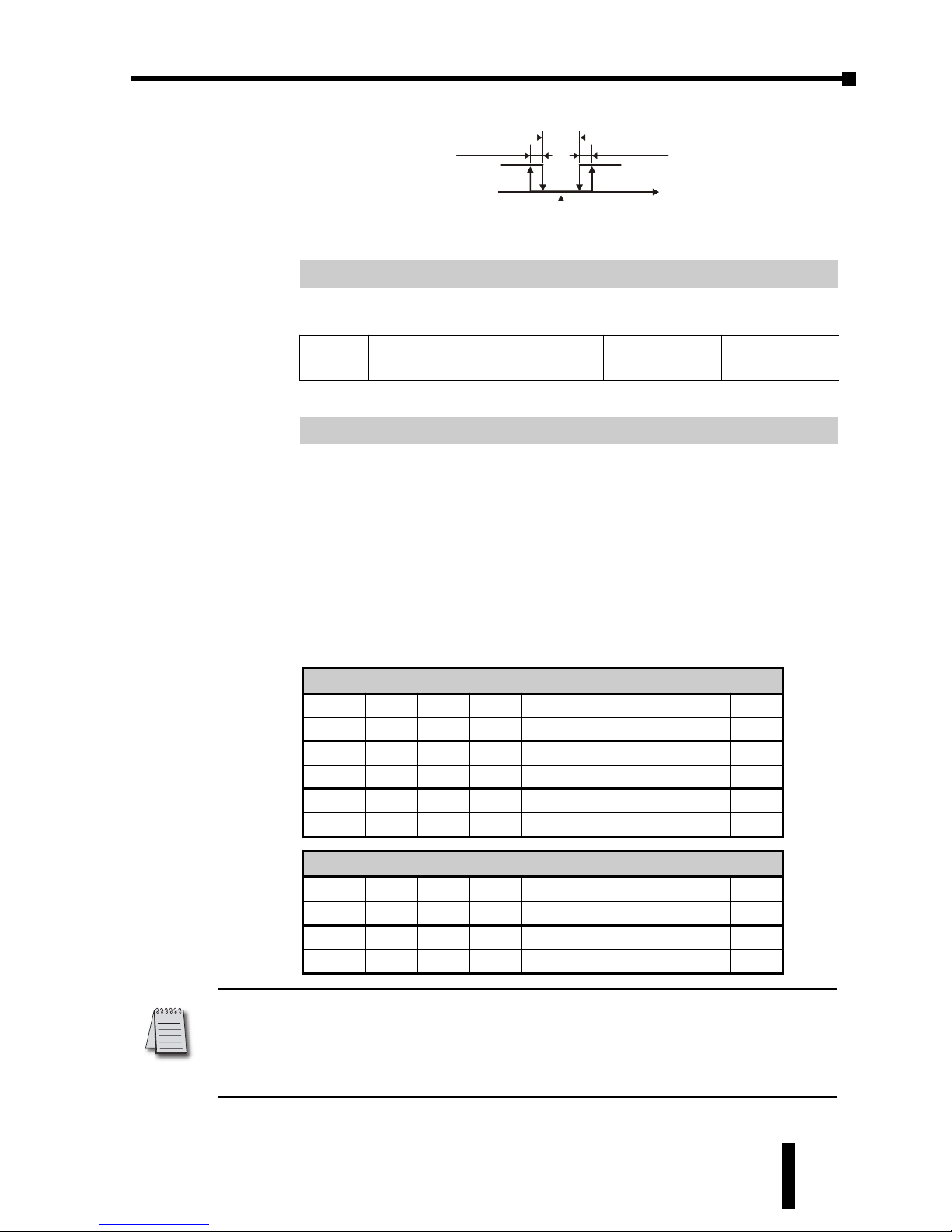
The Analog High Adjustment parameter is used to adjust the actual
analog output value when the output is 100%. To set up this parameter,
place the SOLO controller in the Manual control mode and set the
Output 1 Level (
out1
, P2-11) to 100% then increase / decrease the
parameter value to get the desired analog output value.
The tables below show the approximate Analog High Adjustment
values needed to obtain the desired output value. The actual controller
output will vary. Check and adjust the values until the desired output
level is achieved.
This parameter is available when Output 1 is Current or Linear Voltage.
Note: When decreasing the parameter value for Analog High Adjustment below -1999,
the SOLO display will “roll over” to -0, indicating a value of -2000. Two “roll overs”
equal a value of -4000 and so forth. For example, to enter a value of -5312 for Analog
High Adjustment, hold the ’
,
button until the SOLO display “rolls over” two times
and the display reads -1312.
Voltage Output
0V 1V 2V 3V 4V 5V 6V 7V
Crhi
-7589 -6830 -6071 -5312 -4553 -3795 -3036 -2277
8V 9V 10V 11V 12V 13V 14V 15V
Crhi
-1518 -758 0 759 1518 2277 3036 3795
Current Output
0mA 1mA 2mA 3mA 4mA 5mA 6mA 7mA
Crhi
-7198 -6838 -6478 -6118 -5758 -5398 -5038 -4678
8mA 9mA 10mA 11mA 12mA 13mA 14mA 15mA
Crhi
-4319 -3959 -3599 -3239 -2879 -2519 -2159 -1799
16mA 17mA 18mA 19mA 20mA 21mA 22mA MAX
Crhi
-1440 -1080 -720 -360 0 360 720 722
CrHi
Analog High Adjustment ID Number P1-17
sp
0 1 2 3
tpof
-999 to 999 -99.9 to 99.9 -9.99 to 9.99 -.999 to 0.999
tpof
PV Offset ID Number P1-16
OFF
PV
Set point
ON
Heating
Dead band
Heating hystere sis Cooling hystere sis
Cooling
hts Cts
dead
Dual Loop On / Off control
output operation
Chapter 3: Keypad Operation and Setup Parameters
1st Ed. Rev C 07/08
Page 40
Chapter 3: Keypad Operation and Setup Parameters
SOLO Temperature Controller User Manual
3–14
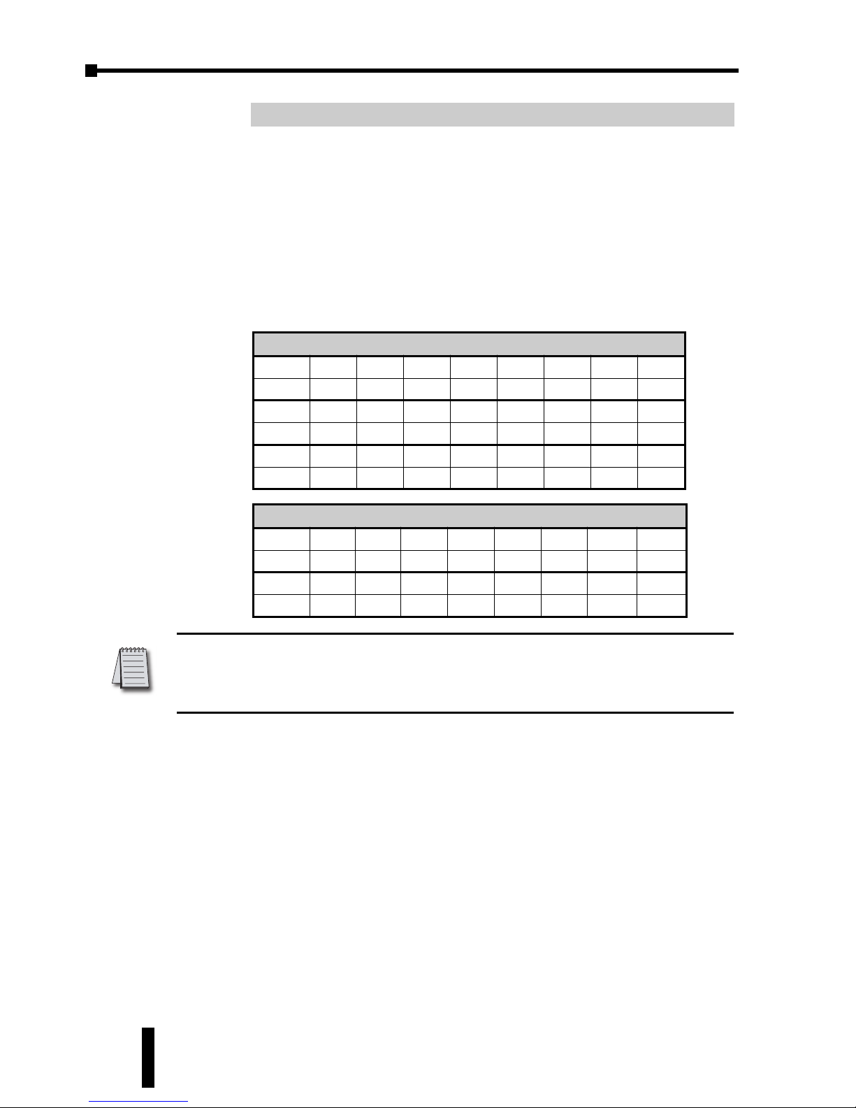
The Analog Low Adjustment parameter is used to adjust the actual
analog output value when the output is 0%. To set up this parameter,
place the SOLO controller in the Manual control mode and set the
Output 1 Level (
out1
, P2-11) to 0% then increase / decrease the
parameter value to get the desired analog output value.
The tables below show the approximate Analog Low Adjustment values
needed to obtain the desired output value. The actual controller output
will vary. Check and adjust the values until the desired output level is
achieved.
This parameter is available when Output 1 is Current or Linear Voltage.
Note: When increasing the parameter value of Analog Low Adjustment above 9999, the
SOLO display will “roll up” to 0000, indicating a value of 10000. For example, to enter
a value of 10625 for Analog Low Adjustment, hold the ’
.
button until the SOLO
display reads 0625.
Voltage Output
0V 1V 2V 3V 4V 5V 6V 7V
Crlo
0 759 1518 2277 3036 3795 4553 5312
8V 9V 10V 11V 12V 13V 14V 15V
Crlo
6071 6830 7589 8348 9107 9866 10625 11384
Current Output
0mA 1mA 2mA 3mA 4mA 5mA 6mA 7mA
Crlo
-1440 -1080 -720 -360 0 360 720 1080
8mA 9mA 10mA 11mA 12mA 13mA 14mA 15mA
Crlo
1440 1799 2159 2519 2879 3239 3599 3959
16mA 17mA 18mA 19mA 20mA 21mA 22mA MAX
Crlo
4319 4678 5038 5398 5758 6118 6478 6480
Crlo
Analog Low Adjustment ID Number P1-18
Page 41
SOLO Temperature Controller User Manual
3–15
Operation Mode Parameters
Press the
'
button to access these parameters.
The Run / Stop parameter is used to control the operational status of
the SOLO Controller. The available range varies according to the
control mode and the status of the EVENT 1 input. The Event 1 input is
available only for the SL4896 and SL9696 series controllers.
Range: 0 to 7
Select the Ramp / Soak pattern number to start the Ramp / Soak
control.
Range: 0 (****)
1 (***.*)
2 (**.**)
3 (*.***)
This parameter defines the decimal point position on the PV and SV
display.
This parameter is used to set the high limit for Alarm 1. The range
al1h
Alarm 1 High Limit ID Number P2-4
sp
Decimal Point Position ID Number P2-3
ptrn
Starting Ramp / Soak Pattern ID Number P2-2
run
Run mode
kstp
Stop mode
stop
Stop mode (The controller was in Stop mode when the
Event 1 input was closed.)
estp
Stop mode (The controller was in Run mode when the
Event 1 input was closed.)
Phod
Ramp / Soak control is on hold. The controller keeps the
current Ramp / Soak step number and time. Ramp / Soak
control continues when the mode is changed to Run.
pstp
Ramp / Soak control is stopped. The controller restarts the
Ramp / Soak control at the first step when the mode is
changed to Run.
Ramp / Soak Control Mode
Run Hold Stop
Event 1 input is off. (Event 1 input is open.)
run phod
kstp,pstp
Event 1 input is on. (Event 1 input is closed.)
N/A N/A
stop,estp
PID, On / Off and Manual Control Modes
Run Stop
Event 1 input is off. (Event 1 input is open.)
run kstp
Event 1 input is on. (Event 1 input is closed.)
N/A
stop,estp
r-s
Run / Stop ID Number P2-1
Chapter 3: Keypad Operation and Setup Parameters
1st Ed. Rev C 07/08
Page 42
Chapter 3: Keypad Operation and Setup Parameters
SOLO Temperature Controller User Manual
3–16
varies according to other parameter values.
This parameter is used to set the low limit for Alarm 1. The range varies
according to other parameter values.
This parameter is used to set the high limit for Alarm 2. The range
varies according to other parameter values.
This parameter is used to set the low limit for Alarm 2. The range varies
according to other parameter values.
This parameter is used to set the high limit for Alarm 3. The range
varies according to other parameter values.
This parameter is used to set the low limit for Alarm 3. The range varies
according to other parameter values.
Lock Mode 1: All key pad operation is ignored. Press the
;
key and
the
'
key at the same time to cancel this lock mode.
Lock Mode 2: All key pad operation is ignored except changing the SV.
Press the
;
key and the
'
key at the same time to cancel this lock
mode.
Range: 0.0 to 100 (%)
The value for this parameter can be changed in the Manual control
mode. In other control modes, this parameter is read-only.
Range: 0.0 to 100 (%)
This parameter is available when Output 2 is used. Refer to the Heating
/ Cooling parameter (
S-HC
, P3-7) to disable / enable Output 2. The
value for this parameter can be changed in the Manual control mode.
In other control modes, this parameter is read-only.
out2
Output 2 Level ID Number P2-12
out1
Output 1 Level ID Number P2-11
Range:
off
The Lock feature is disabled.
loC1
Lock Mode 1
LoC2
Lock Mode 2
loC
Lock Mode ID Number P2-10
al3l
Alarm 3 Low Limit ID Number P2-9
al3h
Alarm 3 High Limit ID Number P2-8
al2l
Alarm 2 Low Limit ID Number P2-7
al2h
Alarm 2 High Limit ID Number P2-6
al1l
Alarm 1 Low Limit ID Number P2-5
Page 43
SOLO Temperature Controller User Manual
3–17
Initial Setting Parameters
Press the
;
button for more than three seconds to access these
parameters.
This parameter defines the input signal type.
Range: F, C
This parameter is available when the parameter Input Type is a
thermocouple or RTD.
tp-h
Input Range High ID Number P3-3
tpun
Temperature Unit ID Number P3-2
Thermocouple Type and Temperature Range
Input Temperature Sensor Type LED Display Temperature Range
Thermocouple TXK type
txk
-328 ~ 1472°F (-200 ~ 800°C)
Thermocouple U type
u
-328 ~ 932°F (-200 ~ 500°C)
Thermocouple L type
l
-328 ~ 1562°F (-200 ~ 850°C)
Thermocouple B type
b
212 ~ 3272°F (100 ~ 1800°C)
Thermocouple S type
s
32 ~ 3092°F (0 ~ 1700°C)
Thermocouple R type
r
32 ~ 3092°F (0 ~ 1700°C)
Thermocouple N type
n
-328 ~ 2372°F (-200 ~ 1300°C)
Thermocouple E type
e
32 ~ 1112°F (0 ~ 600°C)
Thermocouple T type
t
-328 ~ 752°F (-200 ~ 400°C)
Thermocouple J type
j
-148 ~ 2192°F (-100 ~ 1200°C)
Thermocouple K type
k
-328 ~ 2372°F (-200 ~ 1300°C)
RTD Type and Temperature Range
Input Temperature Sensor Type LED Display Temperature Range
Platinum Resistance (Pt100)
pt
-328 ~ 1112°F (-200 ~ 600°C)
Platinum Resistance (JPt100)
jpt
-4 ~ 752°F (-20 ~ 400°C)
Voltage Input Type and Input Range
Voltage Input Type LED Display Temperature Range
0~50mV Analog Input
mv
-999 ~ 9999
0V~10V Analog Input
v10
-999 ~ 9999
0V~5V Analog Input
v5
-999 ~ 9999
Current Input Type and Input Range
Current Input Type LED Display Temperature Range
4~20mA Analog Input
ma4
-999 ~ 9999
0~20mA Analog Input
ma0
-999 ~ 9999
Inpt
Input Type ID Number P3-1
Chapter 3: Keypad Operation and Setup Parameters
1st Ed. Rev C 07/08
Page 44
Chapter 3: Keypad Operation and Setup Parameters
SOLO Temperature Controller User Manual
3–18
Range: From the value of Input Range Low to 9999.
This parameter defines the high limit of the PV. This is the maximum
value of the operational temperature range. In operation, if the PV
value is higher than the
tp-h
value, th PV flashes to indicate an error
and the controller outputs shut off. The SV value cannot exceed the
tp-h
value. This parameter cannot be lower than the Input Range Low
parameter (
tp-l
, P3-4).
Range: From -999 to the value of Input Range High.
This parameter defines the low limit of the PV. This is the minimum
value of the operational temperature range. In operation, if the PV
value is lower than the
tp-l
value, th PV flashes to indicate an error
and the controller outputs shut off. The SV value cannot be set lower
than the
tp-L
value. This parameter cannot be higher than the Input
Range High parameter (
tp-h
, P3-3).
This parameter is used to select one of the control modes. See Chapter
5 for a complete discription of each control mode.
Range: oFF Ramp / Soak pattern is not selected.
0 to 7 Ramp / Soak pattern number.
This parameter is used to select the appropriate Ramp / Soak pattern
number for setting up it’s individual parameters. Once a Ramp / Soak
pattern number (0-7) is selected, the controller only displays the
following pattern setup parameters until the
;
key is pressed.
patn
Ramp / Soak Pattern ID Number P3-6
Range:
pid
PID control mode
onof
On / Off control mode
manu
Manual control mode
pro6
Ramp / Soak control mode
Ctrl
Control Mode ID Number P3-5
tp-l
Input Range Low ID Number P3-4
Page 45
SOLO Temperature Controller User Manual
3–19
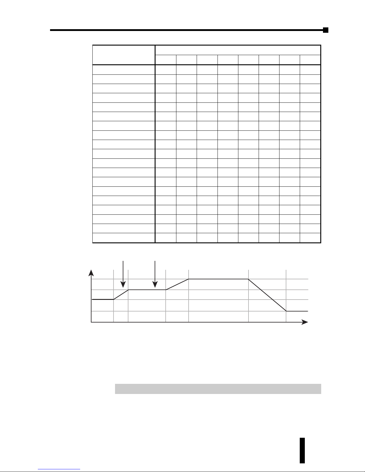
Below is an example of a typical Ramp / Soak Pattern.
s-hC
Heating / Cooling ID Number P3-7
Step00 = 50°
Time00 = 3 hrs 00 min.
Step01 = 70°
Time01 = 2 hrs 00 min.
Step02 = 70°
Time02 = 5 hrs 00 min.
SP00
ti00
SP01
ti01
SP02
ti02
Step03 = 100°
Time03 = 3 hrs 00 min.
Step04 = 100°
Time04 = 8 hrs 00 min.
Step05 = 30°
Time05 = 5 hrs 00 min.
SP03
ti03
SP04
ti04
SP05
ti05
Step06 = 30°
Time06 = 3 hrs 00 min.
Process Step = 6
Cycle times = 0
Link = OFF
SP06
ti06
psx0
CyCO
lin0
100
°
70
°
50
°
30
°
Ramp
03.00
02.00
08.00
Soak
POS0 POS1 POS2 POS3 POS4 POS5 POS6
05.00
03.00
05.00
03.00
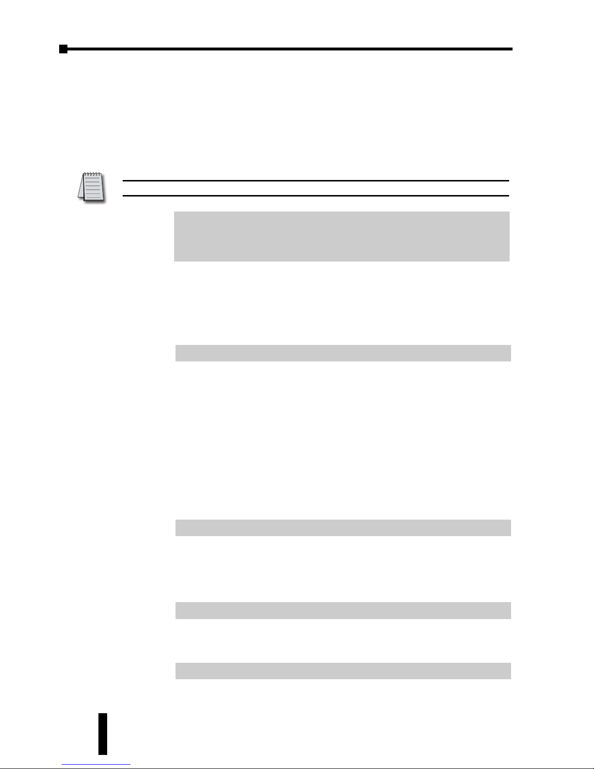
Ramp / Soak Pattern Number
0 1 2 3 4 5 6 7
Step 0 SV
sp00 sp10 sp20 sp30 sp40 sp50 sp60 sp70
Step 0 Time
ti00 ti10 ti20 ti30 ti40 ti50 ti60 ti70
Step 1 SV
sp01 sp11 sp21 sp31 sp41 sp51 sp61 sp71
Step 1 Time
ti01 ti11 ti21 ti31 ti41 ti51 ti61 ti71
Step 2 SV
sp02 sp12 sp22 sp32 sp42 sp52 sp62 sp72
Step 2 Time
ti02 ti12 ti22 ti32 ti42 ti52 ti62 ti72
Step 3 SV
sp03 sp13 sp23 sp33 sp43 sp53 sp63 sp73
Step 3 Time
ti03 ti13 ti23 ti33 ti43 ti53 ti63 ti73
Step 4 SV
sp04 sp14 sp24 sp34 sp44 sp54 sp64 sp74
Step 4 Time
ti04 ti14 ti24 ti34 ti44 ti54 ti64 ti74
Step 5 SV
sp05 sp15 sp25 sp35 sp45 sp55 sp65 sp75
Step 5 Time
ti05 ti15 ti25 ti35 ti45 ti55 ti65 ti75
Step 6 SV
sp06 sp16 sp26 sp36 sp46 sp56 sp66 sp76
Step 6 Time
ti06 ti16 ti26 ti36 ti46 ti56 ti66 ti76
Step 7 SV
sp07 sp17 sp27 sp37 sp47 sp57 sp67 sp77
Step 7 Time
ti07 ti17 ti27 ti37 ti47 ti57 ti67 ti77
Last Step Number
spx0 spx1 spx2 spx3 spx4 spx5 spx6 spx7
Additional Cycles
CyC0 CyC1 CyC2 CyC3 CyC4 CyC5 CyC6 CyC7
Next Pattern Number
Lin0 Lin1 Lin2 Lin3 Lin4 Lin5 Lin6 Lin7
Chapter 3: Keypad Operation and Setup Parameters
1st Ed. Rev C 07/08
Page 46
Chapter 3: Keypad Operation and Setup Parameters
SOLO Temperature Controller User Manual
3–20
The Heating / Cooling parameter defines whether one or two outputs
will be controlled and what type of control they will perform.
Range: 0 to 18
The SOLO controllers support 3 alarm outputs. (The SL4824 series
supports only one alarm output.) The Alarm1, Alarm2 and Alarm3
parameters are used to select the alarm type. Refer to Chapter 4 for
details.
This parameter defines which Alarm output is used for the system
alarm. The System Alarm parameter defines an alarm output if there is
an input error or process control failure. Refer to Chapter 4 for
complete details.
Initial Setting Communication Parameters
Range: 1 to 247
C-no
Network Address ID Number P3-14
Range:
asC~
Modbus ASCII
rtU
Modbus RTU
C-sl
Modbus Protocol ID Number P3-13
Range:
off
Do not allow changes to the parameters through the
RS-485 port.
on
Allow changes to the parameters through the RS-485
port.
Cosh
On-Line Configuration ID Number P3-12
Range:
off
System Alarm feature is disabled
ala1
Alarm 1
ala2
Alarm 2
ala3
Alarm 3
sala
System Alarm ID Number P3-11
ala1
Alarm 1 ID Number P3-8
ala2
Alarm 2 ID Number P3-9
ala3
Alarm 3 ID Number P3-10
Note: Unused Ouput 2 can be used as an Alarm.
Range:
Heat
Output 1 = Heating, Output 2 = Unused
Cool
Output 1 = Cooling, Output 2 = Unused
H1C2
Output 1 = Heating, Output 2 = Cooling
h2C1
Output 1 = Cooling, Output 2 = Heating
Page 47
SOLO Temperature Controller User Manual
3–21
This is the Modbus network address of the SOLO Controller.
Range: 7, 8
Range: None, Even, Odd
Range: 1, 2
Initial Setting Ramp / Soak Parameters
Range: -99.9 to 999.9
This parameter is the set point value (SV) of each Ramp / Soak step.
This parameter can be displayed as
sp00
to
sp77
. The third character
indicates the Ramp / Soak pattern number (m) and the last digit
indicates the step number (n).
e.g.
sp35
= SV set point value of Step 5 of the Ramp / Soak pattern 3.
Range: 00.00 to 15.00 (0 to 15 hours) [Format: hours.minutes]
This parameter is the time duration of each Ramp / Soak step.
This parameter can be displayed as
ti00
to
ti77
. The third character
indicates the Ramp / Soak pattern number (m) and the last digit
indicates the step number (n).
e.g.
TI35
= SV set point value of Step 5 of the Ramp / Soak pattern 3.
Range: 0 to 7
Each Ramp / Soak pattern can have up to seven steps. This parameter is
the last step number that is to be used in the Ramp / Soak pattern.
PSx
n
Last Step Number ID Number P3-21
ti
mn
Ramp / Soak Time ID Number P3-20
SP
mn
Ramp / Soak SV ID Number P3-19
Stop
Stop Bit ID Number P3-18
Prty
Parity ID Number P3-17
len
Bit Length ID Number P3-16
Range:
2400
2400 bps
4800
4800 bps
9600
9600 bps
19kz
19200 bps
38kz
38400 bps
bps
Baud Rate ID Number P3-15
Note: Each controller on the same network must have a unique Modbus network
address.
Chapter 3: Keypad Operation and Setup Parameters
1st Ed. Rev C 07/08
Page 48
Chapter 3: Keypad Operation and Setup Parameters
SOLO Temperature Controller User Manual
3–22
When the parameter value is set to 0, the SOLO controller executes
only step 0 when the Ramp / Soak pattern is selected. When the value
is 7, the controller executes step 0 through step 7 when the Ramp /
Soak pattern is selected.
Range: 0 to 199
As the default, the SOLO controller executes a Ramp /Soak pattern
only once. Use this parameter to set the number of additional times a
Ramp / Soak pattern will execute. When the parameter value is set to
0, the SOLO controller executes the Ramp / Soak pattern one time.
When this parameter value is 2, the Ramp / Soak pattern will execute
two additional times for a total of three executions.
Range: 0 to 7, OFF
This parameter is used to select a Ramp / Soak pattern that will execute
after the current Ramp / Soak pattern is completed. If the parameter
value is set to OFF, the SOLO controller will not begin another Ramp /
Soak pattern after the current pattern.
Reset to Factory Default
The following instructions reset the controller to the factory default.
Press the
'
button until the parameter
loC
appears. Use the
.
button to
select
loC1
. Press the
;
button.
Press and hold the
,
and
.
buttons simultaneously for one second and
release.
Press the
'
button until the PV display shows
pass
. Use the
,
button
to change the value on the SV display to
1357
. Press the
;
button.
Cycle power on the Controller to reset to factory default mode. All user set
values are erased.
Warning: Erasing the user entered values may result in a safety hazard and system
malfunction.
Note: Resetting the Temperature Controller back to factory default erases all of the
values entered by the user. Record any necessary settings before proceeding
lin
n
Next Pattern Number ID Number P3-22
CYC
n
Additional Cycles ID Number P3-22
Page 49
4
4
4
CONTROLLER
INPUTS AND
OUTPUTS
CHAPTER
CHAPTER
CHAPTER
In This Chapter...
Control Input Types . . . . . . . . . . . . . . . . . . . . . . . .4–2
Event Inputs . . . . . . . . . . . . . . . . . . . . . . . . . . . . . .4–3
Control Output Types . . . . . . . . . . . . . . . . . . . . . .4–4
Alarm Outputs . . . . . . . . . . . . . . . . . . . . . . . . . . . .4–8
Page 50
Chapter 4: Controller Inputs and Outputs
SOLO Temperature Controller User Manual
4–2
Control Input Types
Thermocouple or RTD Input
The SOLO temperature controller can accept input from eleven types of
thermocouples and two types of Platinum RTD sensors. Select the sensor type by
using the parameter Input Type (
Inpt
, P3-1).
Analog Input
The SOLO temperature controller can accept input from the following analog
input sources. Select the output type by using the parameter Input Type (
Inpt
,
P3-1).
*Note: For Current Input operation, the supplied 249 ⏲resistor should be installed as
shown on page 4-3.
Voltage Input Type and Input Range
Voltage Input Type LED Display Temperature Range
0~50mV Analog Input
mv
-999 ~ 9999
0V~10V Analog Input
v10
-999 ~ 9999
0V~5V Analog Input
v5
-999 ~ 9999
Current Input Type and Input Range*
Current Input Type LED Display Temperature Range
4~20mA Analog Input
ma4
-999 ~ 9999
0~20mA Analog Input
ma0
-999 ~ 9999
Thermocouple Type and Temperature Range
Input Temperature Sensor Type LED Display Temperature Range
Thermocouple TXK type
txk
-328 ~ 1472°F (-200 ~ 800°C)
Thermocouple U type
u
-328 ~ 932°F (-200 ~ 500°C)
Thermocouple L type
l
-328 ~ 1562°F (-200 ~ 850°C)
Thermocouple B type
b
212 ~ 3272°F (100 ~ 1800°C)
Thermocouple S type
s
32 ~ 3092°F (0 ~ 1700°C)
Thermocouple R type
r
32 ~ 3092°F (0 ~ 1700°C)
Thermocouple N type
n
-328 ~ 2372°F (-200 ~ 1300°C)
Thermocouple E type
e
32 ~ 1112°F (0 ~ 600°C)
Thermocouple T type
t
-328 ~ 752°F (-200 ~ 400°C)
Thermocouple J type
j
-148 ~ 2192°F (-100 ~ 1200°C)
Thermocouple K type
k
-328 ~ 2372°F (-200 ~ 1300°C)
RTD Type and Temperature Range
Input Temperature Sensor Type LED Display Temperature Range
Platinum Resistance (Pt100)
pt
-328 ~ 1112°F (-200 ~ 600°C)
Platinum Resistance (JPt100)
jpt
-4 ~ 752°F (-20 ~ 400°C)
Page 51
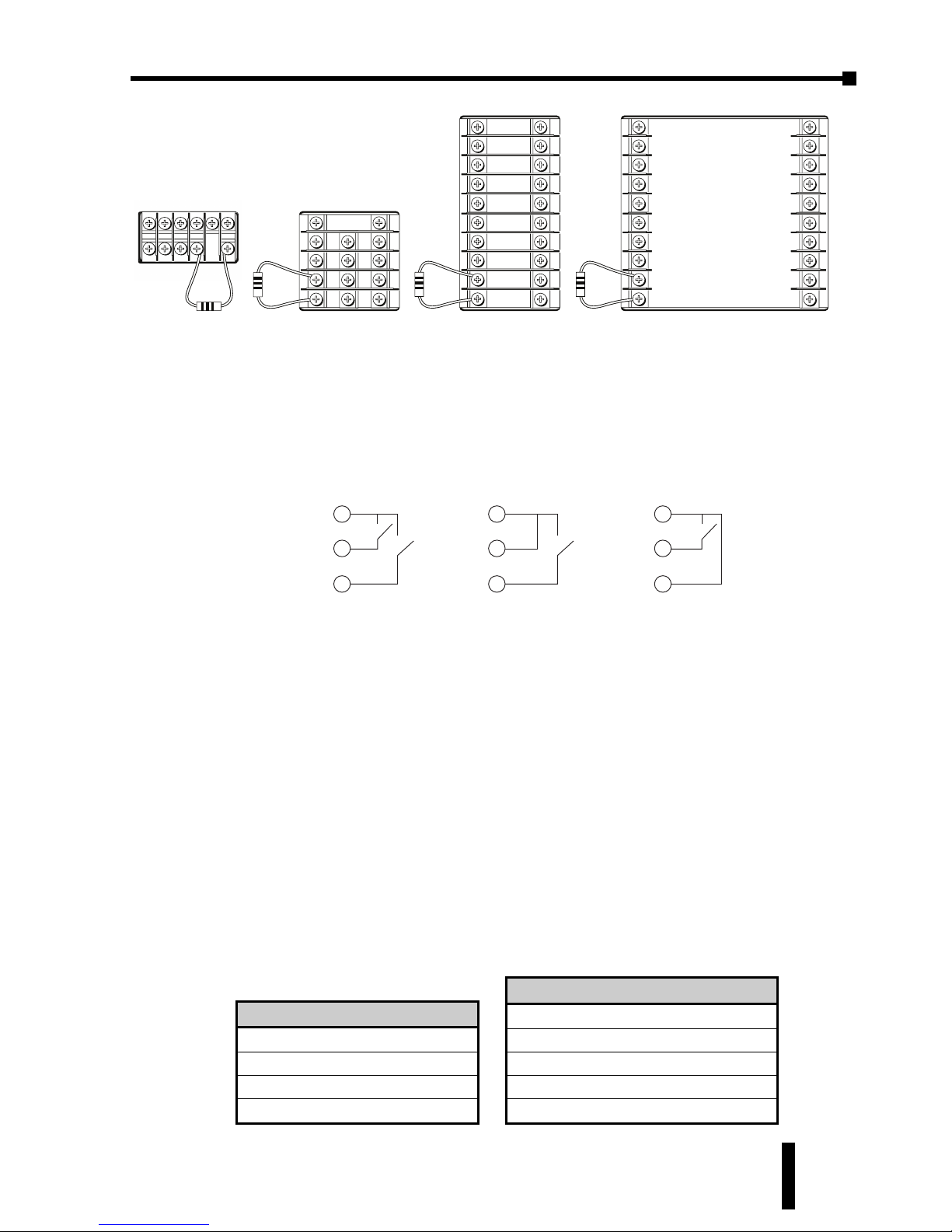
SOLO Temperature Controller User Manual
4–3
Chapter 4: Controller Inputs and Outputs
1st Ed. Rev C 07/08
Event Inputs
The SL4896 and SL9696 series SOLO controllers support two Event inputs, Event
1 and Event 2. When an Event input is not connected to anything (open), the
status of the Event input is off. When the Event input terminal is connected to the
signal ground terminal (SG), the status of the Event input is on.
Event 1 and Event 2 have different functions.
Event 1 Input
Once the Event 1 input is turned on, both control outputs OUT1 and OUT2 are
turned off. This does not effect the status of the alarm outputs. If an alarm output is
on when the Event 1 input is turned on, the alarm output remains on as long as
the condition of the alarm is true.
This Event 1 input can be used to shut down the control outputs quickly with an
external input like a pushbutton or sensor.
Event 2 Input
All SOLO controllers support four PID parameter groups. The SL4896 and SL9696
series SOLO controllers support an additional PID parameter group. When the
Event 2 input is on, the SOLO controller uses the additional PID parameter group.
SL4824 / SL4848
PID Parameter group 0
PID Parameter group 1
PID Parameter group 2
PID Parameter group 3
SL4896 / SL9696
PID Parameter group 0
PID Parameter group 1
PID Parameter group 2
PID Parameter group 3
PID Parameter group (Event 2 is on)
1
2
5
4
3
7
10
9
8
15
14
13
12
11
12
34 6
78
9 10 1211
1
2
5
4
3
6
9
8
7
10
15
14
13
12
11
20
19
18
17
16
1
2
5
4
3
6
9
8
7
10
15
14
13
12
11
20
19
18
17
16
SL4824 SeriesSL4848 SeriesSL4896 SeriesSL9696 Series
249 Ω
249 Ω 249 Ω 249 Ω
3
4
5
SG
Ev1
Ev2
Event 1 and Event 2
are off
3
4
5
SG
Ev1
Ev2
Event 1 is on.
Event 2 is off.
3
4
5
SG
Ev1
Ev2
Event 1 is off.
Event 2 is on.
Page 52
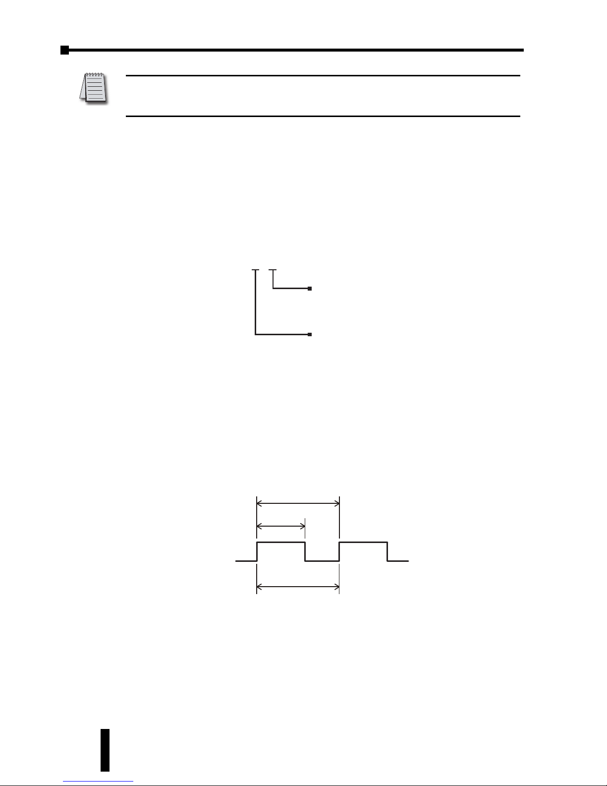
Chapter 4: Controller Inputs and Outputs
SOLO Temperature Controller User Manual
4–4
The Event 2 input can be used to force the Process Value (PV) to reach the
predefined Set Value (SV) when an external input is turned on, but still using the
PID control.
Control Output Types
The SOLO temperature controller supports four types of control outputs
depending on the model chosen. The available outputs are Relay, Voltage Pulse,
Current and Linear Voltage as shown in the controller part number.
Relay Output
The relay used for the relay output is rated at a maximum 250 VAC and 5A
resistive load. The electrical life expectancy is 100,000 operations.
The operation cycle of the Relay output is controlled by two factors, Output Level
and Output Period.
For example, when the Output Level is 60% and the Output Period is 10 seconds,
the output relay is turned on for 6 seconds in the cycle.
There are five parameters that define these two factors.
Output Level
Output 1 Level (
out1
, P2-11) Range: 0.0 to 100%
Output 2 Level (
out2
, P2-12) Range: 0.0 to 100%
1 cycle
Output Level
Output Period
ON
OFF
SL4896 - V R E
2nd Output Group
R: Relay output
V: Voltage Pulse output
1st Output Group
R: Relay output
V: Voltage Pulse output
C: DC Current output
L: Linear Voltage output
Note: The additional PID parameter group can be accessed only when the Event 2
input is on. To edit the PID Parameter group for Event 2 input, Event 2 input must be
on.
Page 53
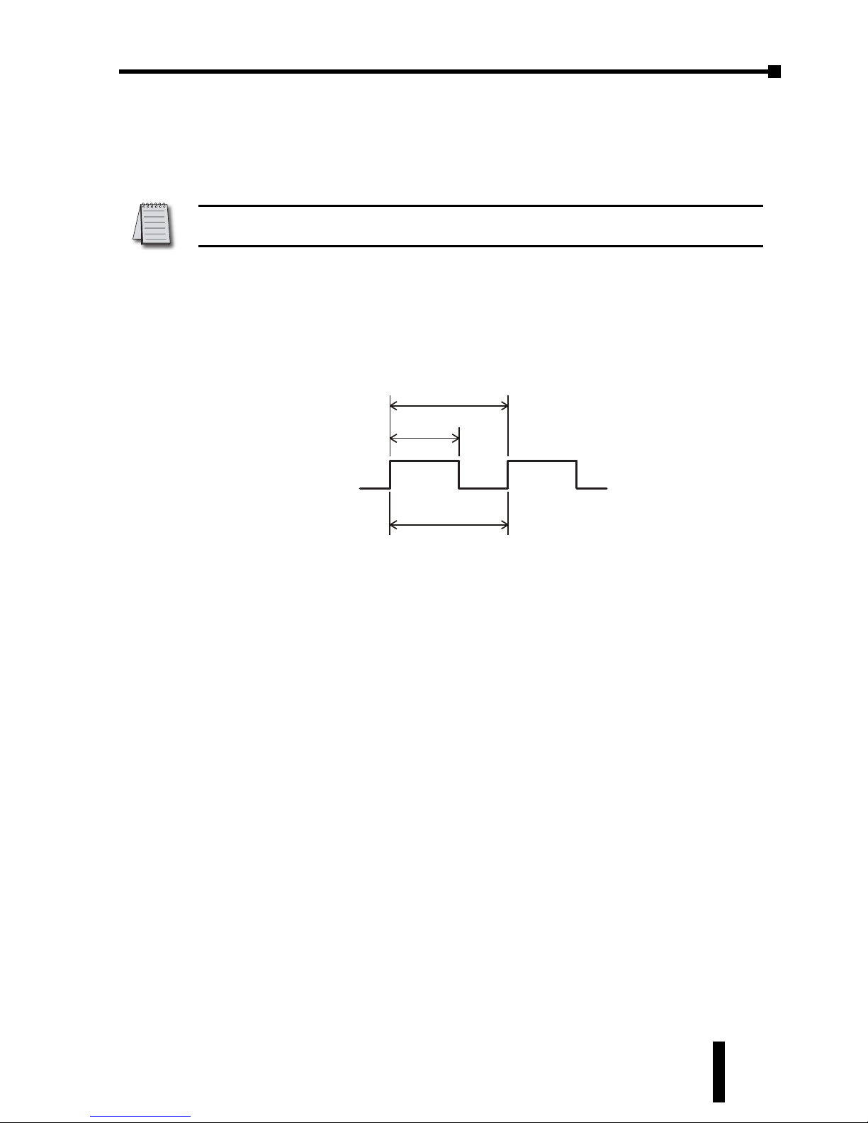
SOLO Temperature Controller User Manual
4–5
Output Period
Output 1 Heating Period (
htpd
, P1-11) Range: 0.5 to 99 seconds
Output 1 Cooling Period (
Clpd
, P1-12) Range: 0.5 to 99 seconds
Output 2 Period (
hCpd
, P1-13) Range: 0.5 to 99 seconds
Voltage Pulse Output
The Voltage Pulse output generates 40 mA pulses. The pulse high level is 14 VDC
and the low level is 0VDC.
The operation cycle of the Voltage Pulse output is controlled by two factors,
Output Level and Output Period.
For example, when the Output Level is 60% and the Output Period is 10 seconds,
the Voltage Pulse output is turned on for 6 seconds in the cycle.
There are five parameters that define these two factors.
Output Level
Output 1 Level (
out1
, P2-11) Range: 0.0 to 100%
Output 2 Level (
out2
, P2-12) Range: 0.0 to 100%
Output Period
Output 1 Heating Period (
htpd
, P1-11) Range: 0.5 to 99 seconds
Output 1 Cooling Period (
Clpd
, P1-12) Range: 0.5 to 99 seconds
Output 2 Period (
hCpd
, P1-13) Range: 0.5 to 99 seconds
Current Output
The Current output generates analog DC current with a range of 4-20 mA. The
maximum load resistance is 600
Ω
The output current is controlled by four factors, Analog High Adjustment, Analog
Low Adjustment, Output Level and Output Period.
1 cycle
Output Level
Output Period
14 VDC
0 VDC
Note: The electrical life expectancy of the relay output is 100,000 cycles. To maximize
the life of the relay output, set a longer time value for the Output Period.
Chapter 4: Controller Inputs and Outputs
1st Ed. Rev C 07/08
Page 54
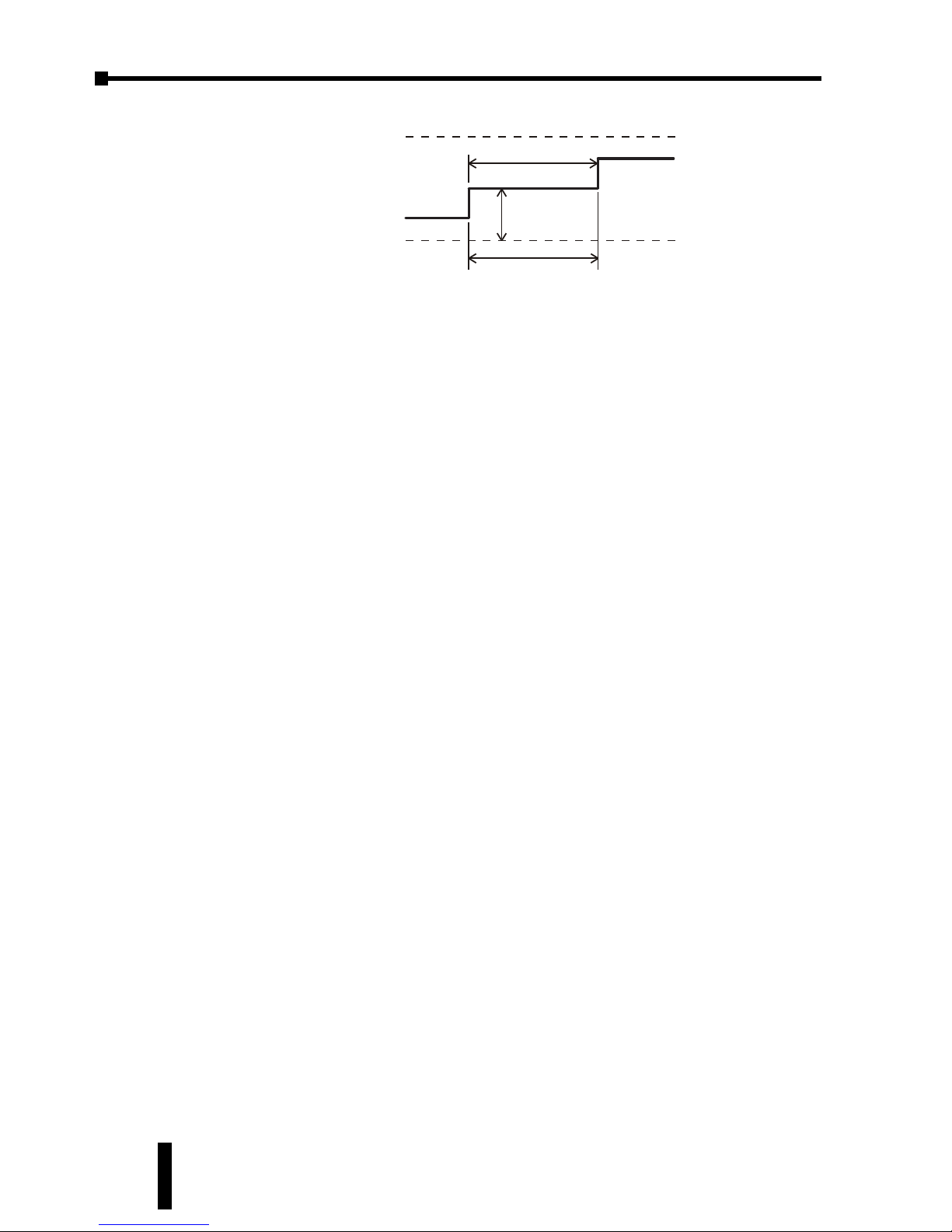
Chapter 4: Controller Inputs and Outputs
SOLO Temperature Controller User Manual
4–6
The Analog High Adjustment value may be changed to adjust the output current
when the Output Level is 100%. The adjustment needs to be done in the Manual
mode.
The Analog Low Adjustment value may be changed to adjust the output current
when the Output Level is 0%. The adjustment also needs to be done in the
Manual mode.
The Output Level determines the output current level between “20mA + Analog
High Adjustment” and “4mA + Analog Low Adjustment”. The output current will
be 10 mA in the following example.
20mA + Analog High Adjustment = 18mA
4mA + Analog Low Adjustment = 2mA
Output Level = 50%
The Output Period sets how often the SOLO controller updates the output value.
There are five parameters that define these four factors.
Analog High Adjustment
Analog High Adjustment (
Crhi
, P1-17)
Analog Low Adjustment
Analog Low Adjustment (
Crlo
, P1-18)
Output Level
Output 1 Level (
out1
, P2-11) Range: 0.0 to 100%
Output Period
Output 1 Heating Period (
Htpd
, P1-11) Range: 0.5 to 99 seconds
Output 1 Cooling Period (
Clpd
, P1-12) Range: 0.5 to 99 seconds
Linear Voltage Output
The Linear Voltage output generates analog voltage from 0-10 VDC. The minimum
load resistance is 1k
Ω.
The output voltage is controlled by four factors, Analog High Adjustment, Analog Low
Adjustment, Output Level and Output Period.
1 cycle
Output Level
Output Period
20 mA + Analog High
Adjustment
4 mA + Analog Low
Adjustment
Page 55
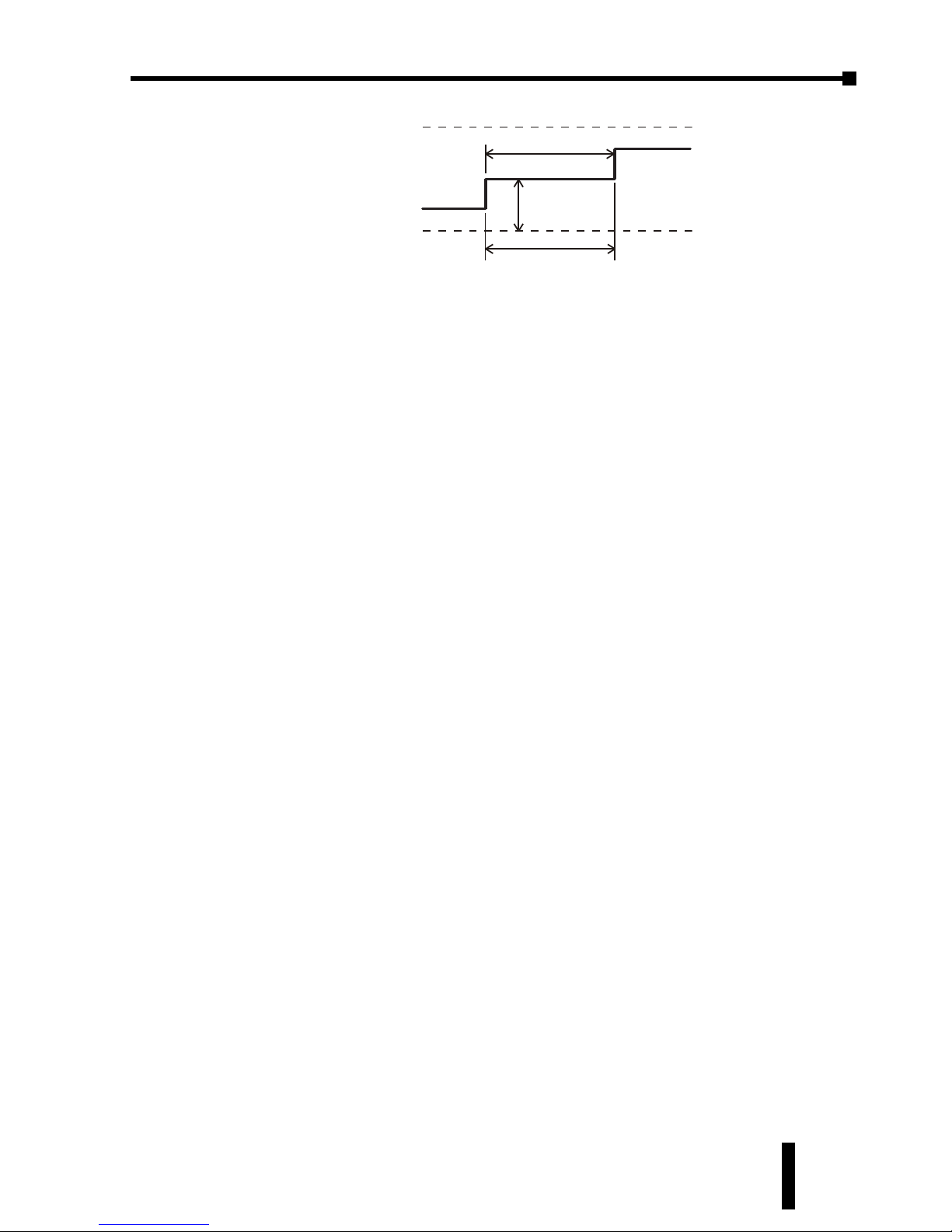
SOLO Temperature Controller User Manual
4–7
The Analog High Adjustment value may be changed to adjust the output voltage
when the Output Level is 100%. The adjustment needs to be done in the Manual
mode.
The Analog Low Adjustment value may be changed to adjust the output voltage
when the Output Level is 0%. The adjustment needs to be done in the Manual
mode.
The Output Level determines the output voltage level between “10 VDC + Analog
High Adjustment” and “0VDC + Analog Low Adjustment”. The output voltage will
be 4 VDC in the following example.
10 VDC + Analog High Adjustment = 7VDC
0VDC + Analog Low Adjustment = 1VDC
Output Level = 50%
The Output Period sets how often the SOLO controller updates the output value.
There are five parameters that define these two factors.
Analog High Adjustment
Analog High Adjustment (
Crhi
, P1-17)
Analog Low Adjustment
Analog Low Adjustment (
Crlo
, P1-18)
Output Level
Output 1 Level (
out1
, P2-11) Range: 0.0 to 100%
Output Period
Output 1 Heating Period (
Htpd
, P1-11) Range: 0.5 to 99 seconds
Output 1 Cooling Period (
Clpd
, P1-12) Range: 0.5 to 99 seconds
1 cycle
Output Level
Output Period
10 VDC + Analog High
Adjustment
0 VDC + Analog Low
Adjustment
Chapter 4: Controller Inputs and Outputs
1st Ed. Rev C 07/08
Page 56
Chapter 4: Controller Inputs and Outputs
SOLO Temperature Controller User Manual
4–8
Alarm Outputs
The SL4848, SL4896 and SL9696 series SOLO controllers support three alarm
output groups (ALA1, ALA2, ALA3) and one system alarm output (SALA). The
SL4824 series SOLO controller supports one alarm output group (ALA1) and one
system alarm output (SALA). ALA1 and ALA2 are both SPST normally open relay
outputs. ALA3 uses the same output as Output 2 and is the same type of output.
See the Alarm Output Chart on the following page.
Note: When Output 2 is used, ALA3 is disabled. ALA3 is available only when single
output control is selected.
Note: The system alarm does not have a dedicated output that can be used only for the
system alarm. One of the alarm outputs can be used for the system alarm. See page
4-11.
Page 57
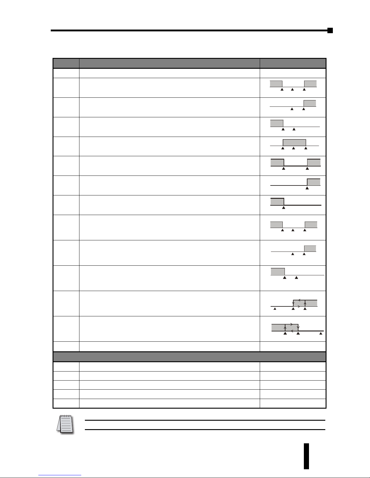
SOLO Temperature Controller User Manual
4–9
Alarm Output Types
Note: ALnH includes AL1H, AL2H and AL3H. ALnL includes AL1L, AL2L and AL3L.
Set Alarm Type Alarm Output Operation
0 Alarm function disabled Output is OFF
1
Deviation upper and lower limit:
This alarm output activates when the PV value is higher than the setting value
SV + ALnH or lower than the setting value SV - ALnL.
ON
OFF
SV - ALnL
SV
SV + ALnH
2
Deviation upper-limit:
This alarm output activates when the PV value is higher than the setting value
SV + ALnH.
ON
OFF
SV
SV+ALnH
3
Deviation lower limit:
This alarm output activates when the PV value is lower than the setting value
SV - ALnL.
ON
OFF
SV
SV - ALnL
4
Reverse deviation upper and lower limit:
This alarm output activates when the PV value is in the range of the setting value
SV+ ALnH and the setting value SV - ALnL.
ON
OFF
SV
SV - ALnL
SV + ALnH
5
Absolute value upper and lower limit:
This alarm output activates when the PV value is higher than the setting value ALnH
or lower than the setting value ALnL.
ON
OFF
ALnL
ALnH
6
Absolute value upper-limit:
This alarm output activates when the PV value is higher than the setting value ALnH
ON
OFF
A
LnH
7
Absolute value lower limit:
This alarm output activates when the PV value is lower than the setting value ALnL
ON
OFF
ALnL
8
Deviation upper and lower limit with standby sequence:
After the PV reaches the SV once, this alarm output activates when the PV value
reaches the set point (SV value) and the reached value is higher than the setting
value SV + ALnH or lower than the setting value SV - ALnL.
ON
OFF
SV
SV - ALnL
SV + ALnH
9
Deviation upper limit with standby sequence:
After the PV reaches the SV once, this alarm output activates when the PV value
reaches the set point (SV value) and the reached value is higher than the setting
value SV+ ALnH.
SV + ALnH
ON
OFF
SV
10
Deviation lower limit with standby sequence:
After the PV reaches the SV once, this alarm output activates when the PV value
reaches the set point (SV value) and the reached value is lower than the setting
value SV - ALnL.
SV - ALnL
ON
OFF
SV
11
Hysteresis upper-limit alarm output:
This alarm output activates when the PV value is higher than the setting value
SV + ALnH. This alarm output is OFF when the PV value is lower than the setting
value SV + ALnL.
ON
OFF
SV + ALnL
SV
SV + ALnH
12
Hysteresis lower-limit alarm output:
This alarm output activates when the PV value is lower than the setting value
SV- ALnH. This alarm output is OFF when the PV value is higher than the setting
value SV - ALnL.
ON
OFF
SV - ALnH
SV
SV - ALnL
13 N/A
Ramp / Soak Program Alarms
14 This alarm activates when the Ramp / Soak program has ended.
15 This alarm activates while the program is in RAMP UP status.
16 This alarm activates while the program is in RAMP DOWN status.
17 This alarm activates while the program is in SOAK status.
18 This alarm activates while the program is in RUN status.
Chapter 4: Controller Inputs and Outputs
1st Ed. Rev C 07/08
Page 58
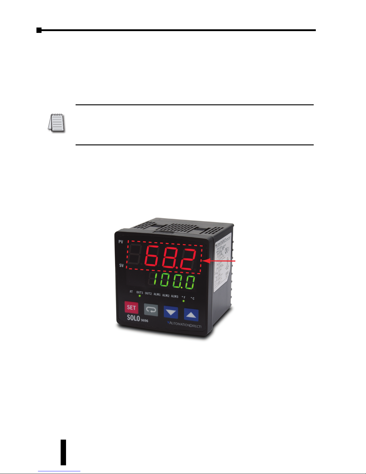
Chapter 4: Controller Inputs and Outputs
SOLO Temperature Controller User Manual
4–10
System Alarm Output
The system alarm can be used to indicate the following system error.
System Error: The SOLO controller checks the control outputs for correct
operation by monitoring the PV value. If the heating output is on but the PV keeps
dropping for two minutes, the system alarm turns on. Or, if the cooling output is
on but the PV continues to increase for two minutes, the system alarm turns on.
On series SL4848, SL4896 and SL9696 controllers, the system alarm can be
assigned to one of the alarm outputs 1 - 3. Series SL4824 supports only one alarm
output. Use the System Alarm Parameter
(
SALA
, P3-11) to set the alarm output
number.
The system alarm can be disabled by setting the System Alarm (
SALA
, P3-
11) to OFF.
When the system alarm output is on, the corresponding Alarm Output is on and
the PV display on the controller starts flashing.
Note: The SOLO controller checks the PV every 15 seconds. If the PV continues
increasing / decreasing eight times when the controller checks the PV, the system alarm
turns on. (15 seconds x 8 = 2 minutes). If the PV does not increase / decrease when
the controller checks it, the controller resets the counter. The PV would have to
increase / decrease for an additional two minutes to activate the alarm.
Flashes
Page 59
5
5
5
CONTROL MODES
CHAPTER
CHAPTER
CHAPTER
In This Chapter...
PID Control . . . . . . . . . . . . . . . . . . . . . . . . . . . . . .5–2
On / Off Control . . . . . . . . . . . . . . . . . . . . . . . . . .5–3
Ramp / Soak Control . . . . . . . . . . . . . . . . . . . . . . .5–4
Manual Control . . . . . . . . . . . . . . . . . . . . . . . . . . .5–5
Error Display Information . . . . . . . . . . . . . . . . . . . .5–5
Page 60
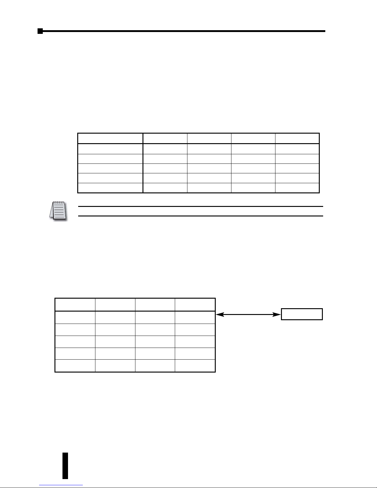
Chapter 5: Control Modes
SOLO Temperature Controller User Manual
5–2
The SOLO controller can be configured for any of the following control modes.
• PID control
• On / Off control
• Ramp / Soak control
• Manual control
PID Control
All of the SOLO controllers can store up to four PID parameter groups (PID
parameter groups 0 - 3)
The operator can select any of the parameter groups for PID control. The SOLO
controller also supports the PID parameter group 4. However, this is not an actual
parameter group. When the PID parameter group 4 is selected, the controller
checks the SV of each parameter group and uses the parameter group which has a
SV that is the closest to the SVset by the operator. If there are two or more PID
parameter groups that have SV values equally close to the SV, the controller uses
the lowest number parameter group (eg. If parameter groups 0 - 3 have the same
SV, the controller uses the parameter group 0).
Once the controller selects one of the PID parameter groups (group 0 - 3), the
setup parameters of the selected parameter group are displayed on th controller.
The SL4896 and SL9696 series controller also support an additional PID
parameter group. The parameter group is used with the Event2 input. When
Event2 input is on, the SOLO controller uses the additional PID group for the PID
control.
Group 0 Group 1 Group 2 Group 3
sv0 sv1 sv2 sv3
p0 p1 p2 p3
i0 i1 i2 i3
d0 d1 d2 d3
iof0 iof1 iof2 iof3
When the PID parameter group 4
is selected, the controller
compares SV0 - SV3 with the PV.
Then it uses the parameter group
which has a SV that is the closest
to the SV set by the operator..
Group 4
SV
Note: Other parameters are shared among all PID parameter groups.
Group 0 Group 1 Group 2 Group 3
Set Value
sv0 sv1 sv2 sv3
Proportion Band
p0 p1 p2 p3
Integral Time
i0 i1 i2 i3
Derivative Time
d0 d1 d2 d3
Integral Offset
iof0 iof1 iof2 iof3
Page 61
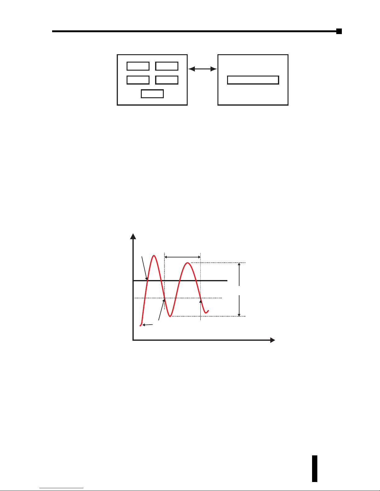
SOLO Temperature Controller User Manual
5–3
Chapter 5: Control Modes
1st Ed. Rev C 07/08
Auto Tuning
All SOLO controllers support the Auto Tuning feature to set up the following PID
parameters automatically.
To start the Auto Tuning, set the parameter Auto Tuning (
AT
, P1-1) to on. the
controller automatically controls the output to change the PV as shown below.
Once the Auto Tuning process is completed, the SOLO controller calculates the
above PID parameters and starts the PID control with the new parameter values
immediately.
On / Off Control
In the On / Off control mode the output is controlled according to the difference
between the SV and the PV. If the PV is lower than the SV, the heating output is
turned on. If the PV is higher than the SV, the cooling output is turned on. The
Heating / Cooling Hysteresis and the Dead Band setups can be used to avoid
output chatter.
p
Proportional Band (Pn, P1-4)
i
Integral Time (In, P1-5)
d
Derivative Time (dn, P1-6)
iof
Integral Offset (
iof
n, P1-8)
Coef
Proportional Band Coefficient (
Coef
, P1-14)
Group 0
Group 2
Group 1
Group 3
Group 4
Event 2 = Off
Group for Event 2
Event 2 = On
Control output
turns off
Temperature
SV
SV- 2
Control output
turns on
Cycle
Amplitude
The Auto Tuning ends and
the PID control starts
Time
Page 62
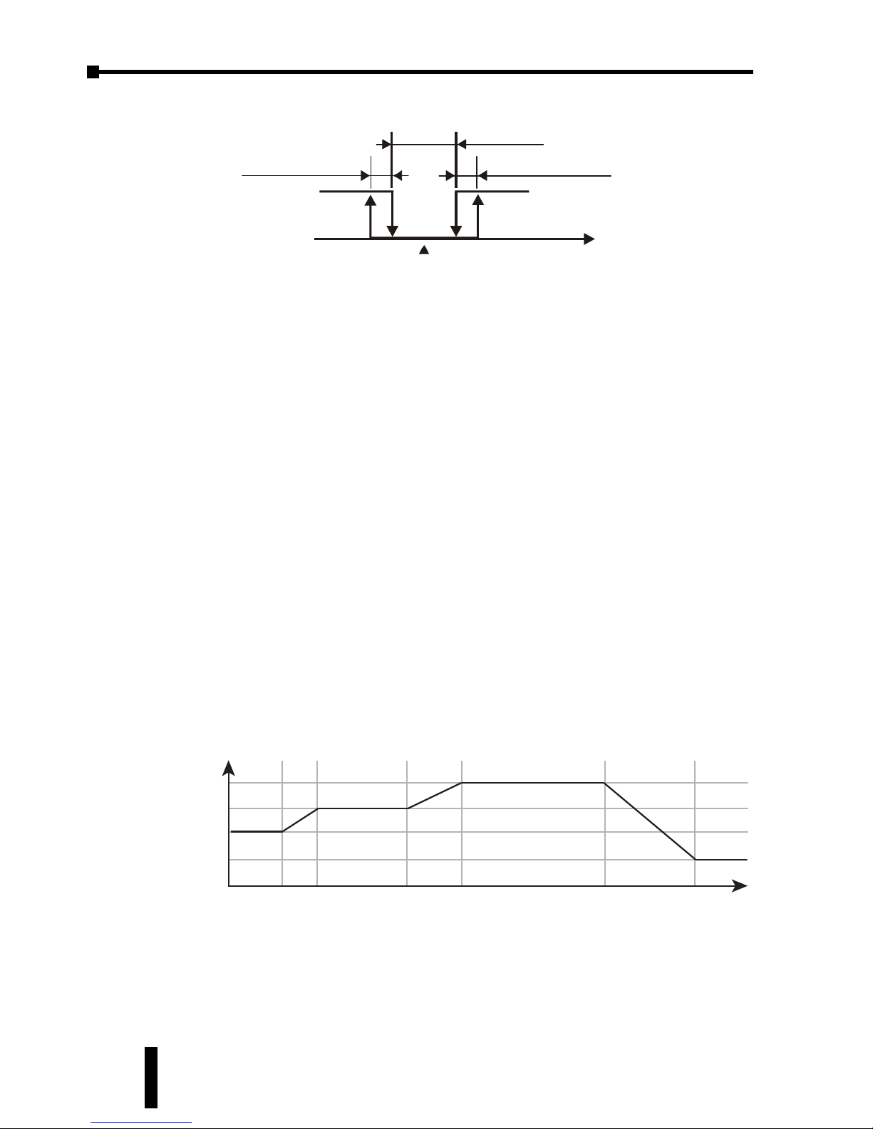
Chapter 5: Control Modes
SOLO Temperature Controller User Manual
5–4
Hysteresis
There are two types of hysteresis, heating and cooling. If the heating hysteresis is
set, the heating output turns on using the following formula.
PV < SV - (
dead
/ 2) -
hts
If the cooling hysteresis is set, the cooling output turns on using the following
formula.
PV > SV + (
dead
/ 2) +
Cts
Dead Band
The Dead Band is the range around the PV in which the heating / cooling outputs
remain off. The Dead Band is defined by the formula.
SV ± (
dead
/ 2)
Ramp / Soak Control
The Ramp / Soak control mode is used to control the outputs according to the
preprogrammed SV patterns with the PID control method. The SOLO controllers
support up to eight Ramp / Soak patterns. Each Ramp / Soak pattern can store up
to eight steps. Each step has its target SV and the time duration setups. You can set
up each Ramp / Soak step.
You can select which Ramp / Soak pattern the SOLO controller will execute first.
The Ramp / Soak patterns can be executed in series, so the Ramp / Soak control
can execute up to 64 steps (8 steps x 8 patterns). You can select which Ramp /
Soak pattern will execute next or the controller stops after executing the current
pattern.
Step0
Step1
Step2
Step3
Step4
Step5
Step6
Temperature
Time
dead
Dead band
ON
OFF
(P1-9)
Heating
Cooling
Set point
hts Cts
Heating hysteresis Cooling hysteresis
(P1-15)
(P1-10)
PV
Page 63
SOLO Temperature Controller User Manual
5–5
The SOLO controller can execute the same Ramp / Soak pattern up to 200 times
before it stops or moves to the next Ramp / Soak pattern.
Ramp / Soak Display
There are three Ramp / Soak display modes possible with the SOLO controller.
From the controller main screen press the
.
and
,
buttons to choose from
these three optional display modes.
p-st
- Pattern Number - Step Number
sp
- Set Point
r-ti
- Remaining time in current step
Press the
;
button to save the selection.
Manual Control
In the Manual control mode, the outputs of the controller are manipulated
manually by the operator. Adjust the values of the parameters Output 1 Level
(
out1
, P2-11) and / or Output 2 Level (
out2
, P2-12) to control the output
levels. Output 2 Level is only available when you select a dual output mode.
Error Display Information
The chart below illustrates the possible error displays shown on the SOLO
Temperature controller.
Controller Error Display
Display
Position
Display Meaning Cause Corrective Action
PV
b160
Cr
Initialization
PV = Firmware
version
SV = Module type
The controller is
in the
initialization
process.
The SOLO controller displays this information
for a few seconds after power up. If the
controller continues displaying this information,
check the input wiring. If the problem still
exists, replace the sensor or the controller.
SV
PV
no
Cont
No sensor input
The input
terminals are
open.
Check the input wiring. If the problem still
exists, replace the sensor or the controller.
SV
PV
Err
Inpt
Input error
The controller
cannot read the
input value
Check the sensor and the input wiring. If the
problem still exists, replace the sensor or the
controller.
SV
PV
Err
Prom
EEPROM error
There is an error
with the
EEPROM
Cycle the power to the SOLO controller. If the
problem still exists, replace the controller.
SV
PV
Flashing PV PV out of range
The PV is out of
range
Check the PV range. The Input Range High
(
TP-H
, P3-3) and the Input Range Low
(
TP-l
, P3-4) parameters define the range.
Refer to section 12-1, 12-2 or 12-3 for
directions on how to access these parameters.
SV
Chapter 5: Control Modes
1st Ed. Rev C 07/08
Page 64

Page 65
6
6
6
CONFIGURATION
SOFTWARE
CHAPTER
CHAPTER
CHAPTER
In This Chapter...
PC Connection . . . . . . . . . . . . . . . . . . . . . . . . . . .6–2
Software Installation . . . . . . . . . . . . . . . . . . . . . . .6–3
Com port Settings . . . . . . . . . . . . . . . . . . . . . . . . .6–4
Configuration . . . . . . . . . . . . . . . . . . . . . . . . . . . .6–4
Recorder . . . . . . . . . . . . . . . . . . . . . . . . . . . . . . . .6–7
Page 66
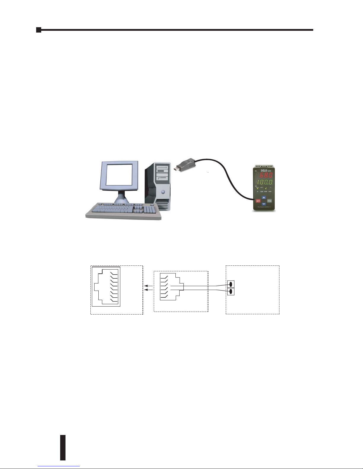
Chapter 6: Configuration Software
SOLO Temperature Controller User Manual
6–2
The SOLO temperature controller can be configured and monitored by the SOLO
Configuration Software. It is available at the following URL for free download.
http://support.automationdirect.com/downloads.html
PC Connection
To connect a PC to the SOLO controller, you will need the following component
from AutomationDirect.
• USB-485M (USB to RS-485 communication adapter)
Use the supplied black 2-wire cable to connect the USB adapter to the SOLO
controller. Plug the adapter into one of the PC’s USB ports.
USB-485M
Black 2-Wire Cable
(supplied with USB-485M)
USB-485M Converter
1
4 (SG+)
5 (SG–)
8
RJ45 Receptacle
USB-485M
black 2-wire cable
1
3
4
6
RJ12 Plug
red
green
Flying
Leads
SOLO controller
SOLO
Temperature Controller
Data + (RS-485)
Data – (RS-485)
Terminals
Page 67
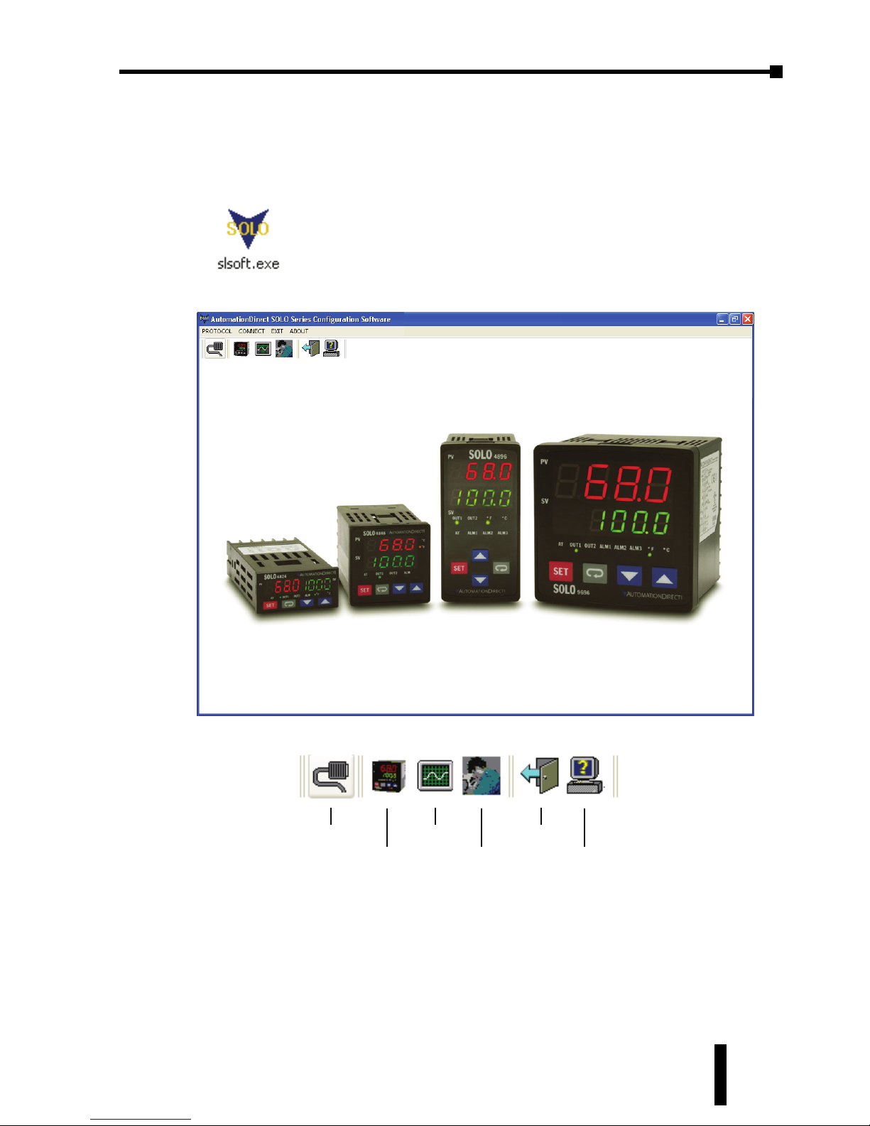
SOLO Temperature Controller User Manual
6–3
Chapter 6: Configuration Software
1st Ed. Rev C 07/08
Software Installation
Download slsoft.exe from the above URL and copy the content onto your
computer at the location you prefer. This software does not require an installation
application. Just double click on the program icon to start working.
You will see the following screen when the Configuration Software opens.
There are six icons that are assigned to the main menu.
Com port setup
Configuration
Recorder
Command Test
Exit
About
Page 68
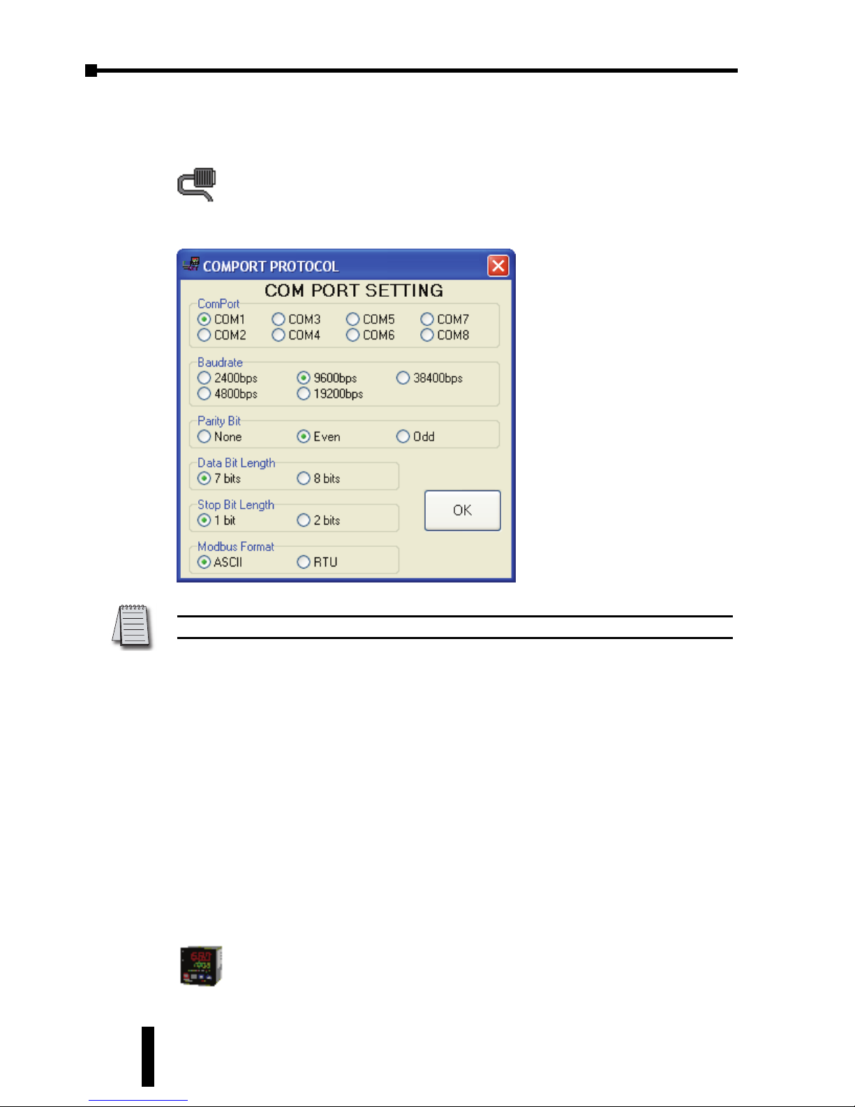
Chapter 6: Configuration Software
SOLO Temperature Controller User Manual
6–4
Com port Settings
Click on the icon below or select the PROTOCOL menu at the top of the window
The window below opens.
1. ComPort: Select the com port on your PC to be used for communicating to the
SOLO controller.
2. The remaining com port settings should match the RS-485 communication port
setup on the controller.
3. Click the OK button once all parameters are set.
Your PC is now able to communicate to the SOLO Controller. Proceed to one of
these sections.
• If you want to configure the controller Configuration
• If you want to monitor / record the PV Recorder
Configuration
To connect to the SOLO controller, click the following icon.
Note: The above graphic shows the default RS-485 setup for the SOLO Controller.
Page 69
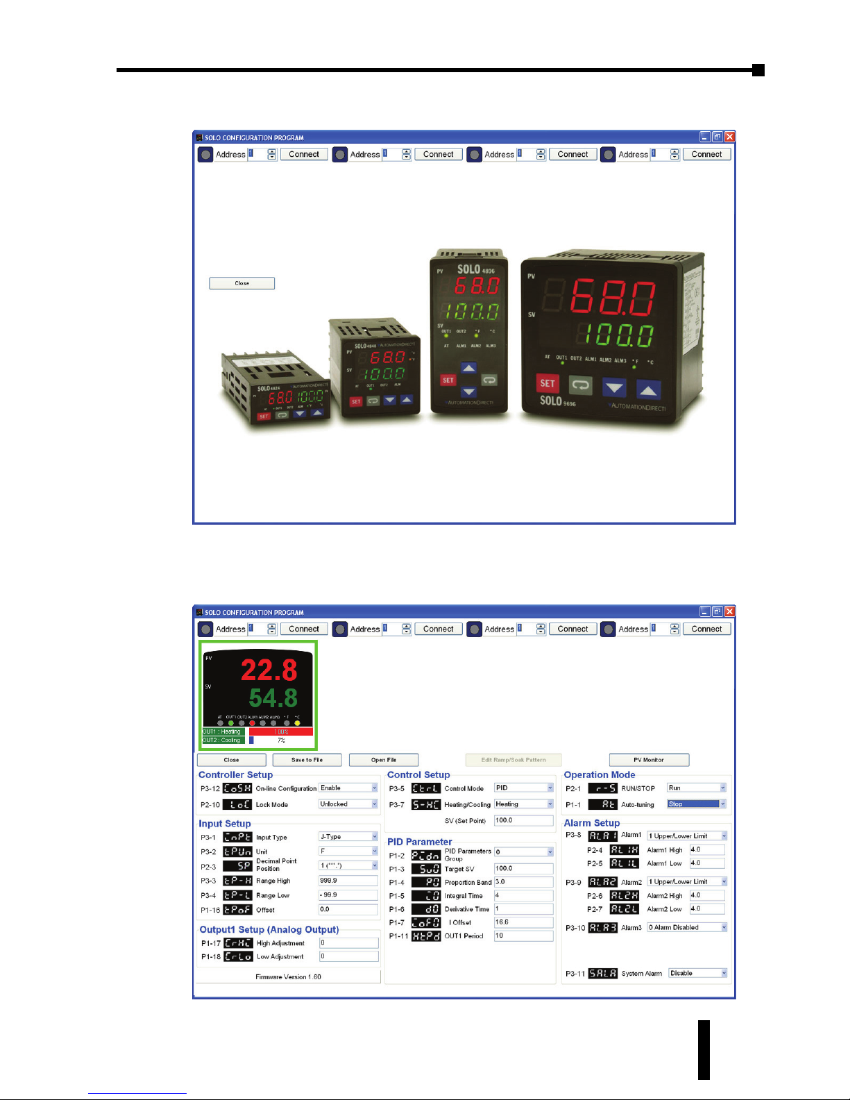
SOLO Temperature Controller User Manual
6–5
The Configuration window opens.
You can configure up to four SOLO controllers at the same time. Select the
Modbus address of the SOLO controller that you want to configure and click the
Connect button. The following window opens.
Chapter 6: Configuration Software
1st Ed. Rev C 07/08
Page 70
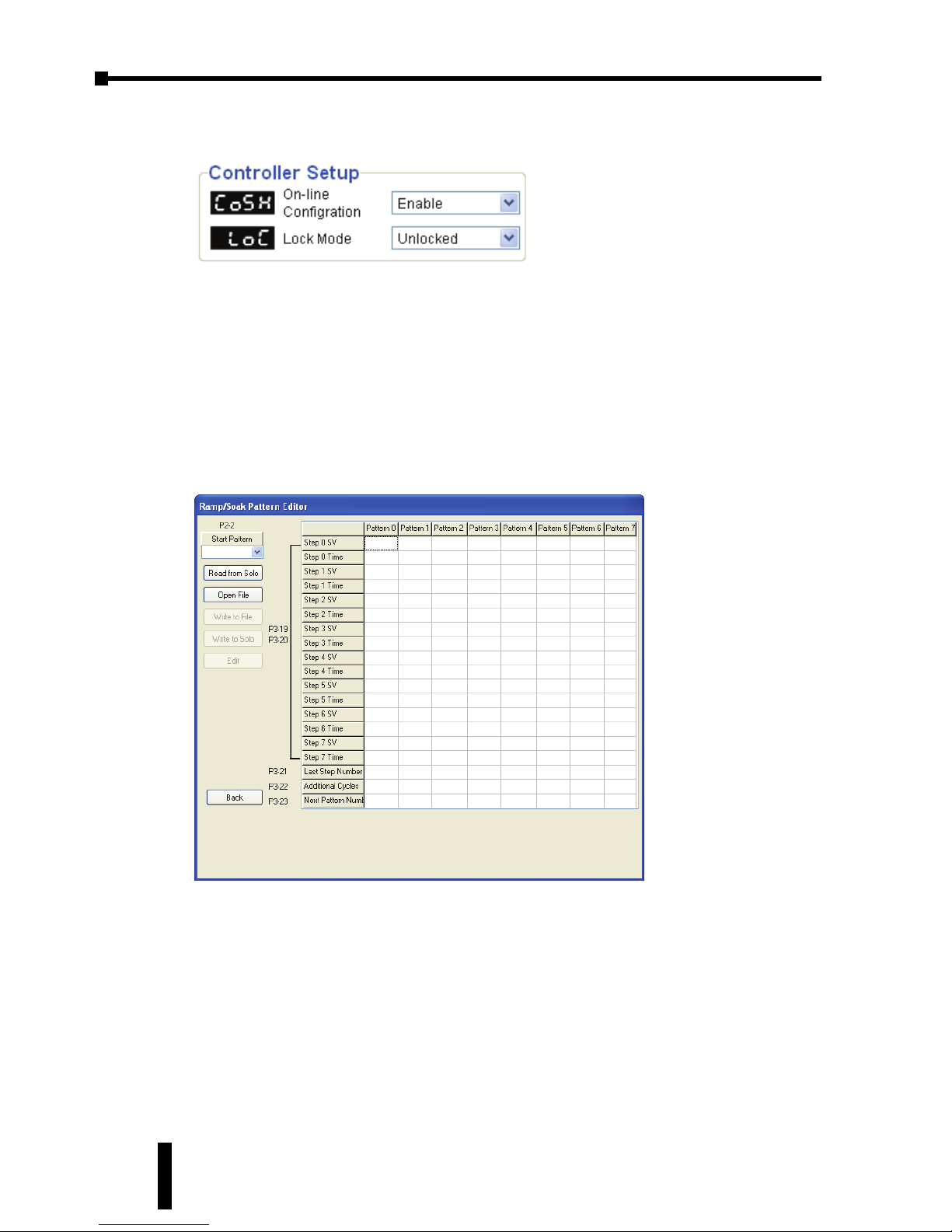
Chapter 6: Configuration Software
SOLO Temperature Controller User Manual
6–6
To configure the SOLO controller from the software, ensure that the parameter
On-Line Configuration is enabled and the Lock Mode is unlocked.
Now any parameter can be changed. Press the Enter key after entering the new
parameter value and the software will send the new value to the controller
immediately.
If you want to save the current configuration, click the Save to File button. You can
read an existing configuration file by clicking the Open File button.
You can monitor the current PV by clicking the PV Monitor button.
When you select the Ramp / Soak Control mode, you can open the Ramp / Soak
pattern edit window by clicking the Edit Ramp/Soak Pattern button. The following
window opens.
Click the Read Setting button to read the current Ramp /Soak pattern(s) from the
SOLO controller.
Start Pattern:
Select the pattern number that the Ramp / Soak mode starts with.
Read from Solo: Read the Ramp / Soak patterns from the SOLO controller.
Open File: Open an existing Ramp / Soak pattern file.
Write to File: Save the current Ramp / Soak pattern(s) into a file.
Write to Solo: Write the Ramp / Soak pattern(s) into the SOLO controller.
Edit: Edit the setup value that the cursor indicates.
Back: Close the Ramp / Soak pattern edit window.
Page 71
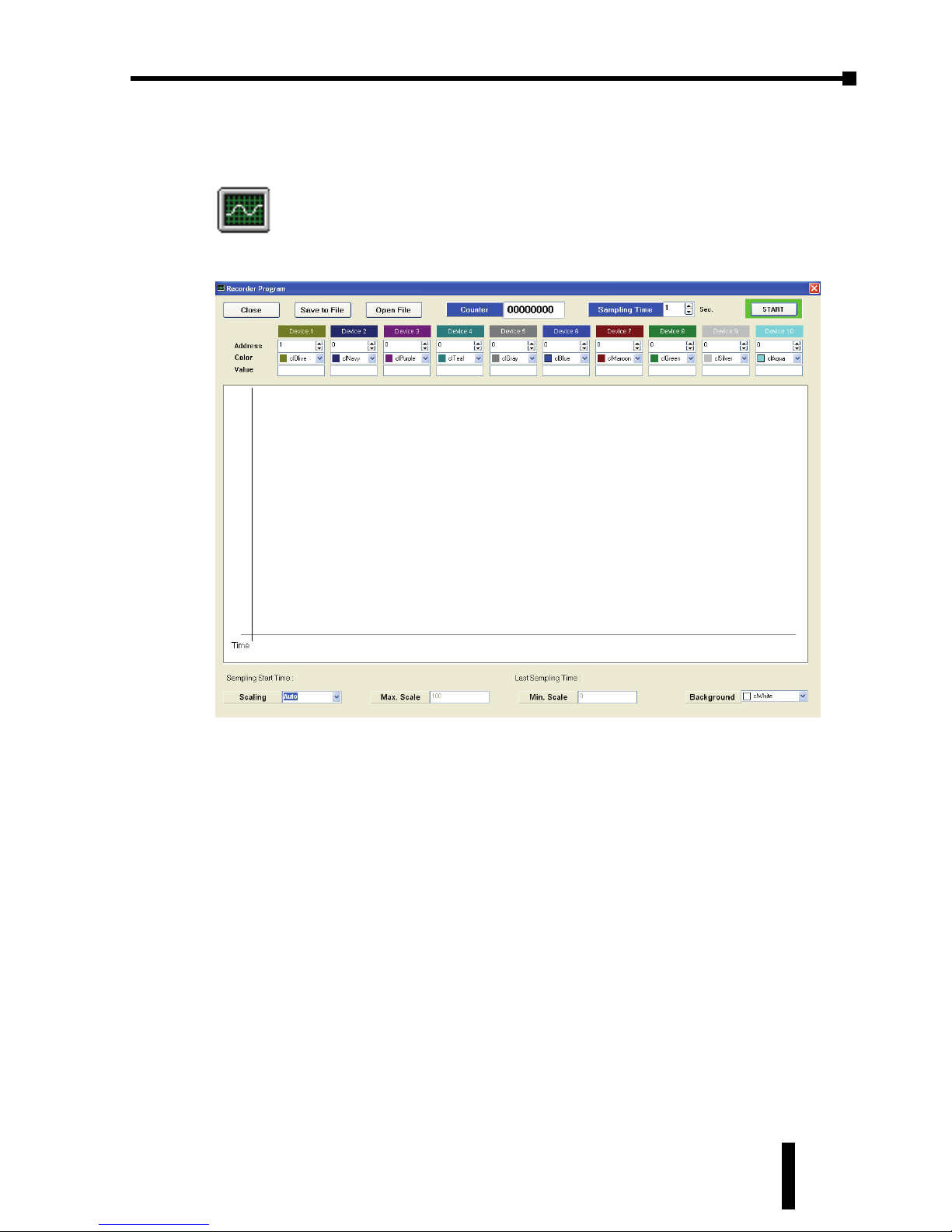
SOLO Temperature Controller User Manual
6–7
Recorder
To open the Recorder window, click the following icon.
The Recorder window opens.
The Recorder allows you to monitor and record the PV of up to ten SOLO
controllers at the same time. Select the Modbus address of each SOLO controller
and the color of your choice. Adjust the sampling time at the top of the window.
Last, click the START button on the right top of the window to begin recording the
PV.
The SOLO configuration and monitoring software allows the user to save a .txt file
of the process values recorded in the software. To create a new file and save the
values, use this procedure.
1. Click the Save to File button and create a new .txt file. Give the new file a
unique name and choose an appropriate location to save the file. At this point
the new file has not been written to disk.
2. Click the Start button. The new file is created and the software will start
recording data on te trend chart.
3. Click the Stop button when the desired amount of data is recorded. The new
file is saved to disk.
After the file has been saved to disk, the file can be opened by clicking the Open
File button.
Chapter 6: Configuration Software
1st Ed. Rev C 07/08
Page 72

Page 73
7
7
7
MODBUS
COMMUNICATION
CHAPTER
CHAPTER
CHAPTER
In This Chapter...
Modbus Protocol . . . . . . . . . . . . . . . . . . . . . . . . . .7–2
Registers . . . . . . . . . . . . . . . . . . . . . . . . . . . . . . . .7–2
Connection with the DirectLOGIC PLC . . . . . . . . .7–7
Connection with the C-more
and C-more Micro HMI panels . . . . . . . . . . . . . . . .7–9
Page 74
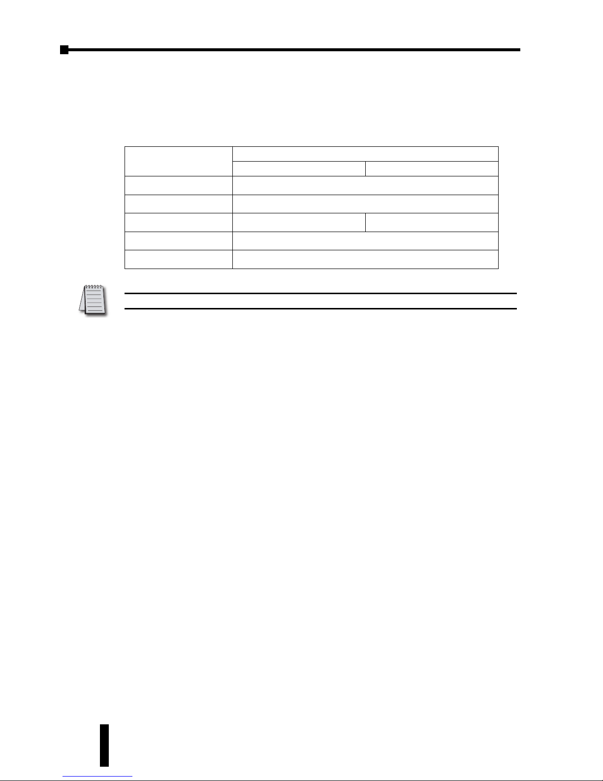
Chapter 7: Modbus Communication
SOLO Temperature Controller User Manual
7–2
Modbus Protocol
All of the SOLO controllers have a 2-wire RS-485 serial communication port. The
supported protocols are Modbus RTU and Modbus ASCII. The following
communication port settings are possible.
Registers
The SOLO controllers support two types of registers that are accessible through
the Modbus communication.
• Data Registers
• Bit Registers
These registers support the following Modbus function codes.
Data Registers
03: Read Holding Registers (maximum limit is read of eight registers)
06: Write Single Register
16: Write Multiple Registers (maximum limit is eight)
Bit Registers
01: Read Coils
02: Read Discrete Inputs (Both Function Code 1 & 2 read the same memory area.)
05: Write SIngle Coil (Write FF00H to set the coil or 0000H to reset the coil.)
The following tables show all the Modbus addresses that are accessible through
the Modbus network. For the details of each parameter, please refer to Chapter 3.
Protocol
Modbus RTU Modbus ASCII
Network Address 1 to 247
Baud Rate 2400, 4800, 9600, 19200, 38400 bps
Bit Length 8 bits 7, 8 bits
Parity None, Even, Odd
Stop Bit 1, 2 bits
Bold Italic text above represent default values in the SOLO controller.
Page 75
SOLO Temperature Controller User Manual
7–3
Chapter 7: Modbus Communication
1st Ed. Rev C 07/08
Data Registers
ID Parameter Name Description
R/WHexadecimalModbus
Decimal
PLC
Address
(Octal)
N/A Process Value (PV) If this register has one of the
following values, it means
there is an error:
8002H = Initial process
(Temperature value is not yet
available.)
8003H - Temperature sensor
is not connected.
8004H = Temperature
sensor input error
8006H = Cannot get
temperature value, ADC
input error
8007H Memory read / write
error
R 1000 44097 V10000
N/A Set Point Value (SV) Unit is 0.1 (°C or °F) R/W 1001 44098 V10001
P3-3 Input Range High The data content should not
be higher than the
temperature range.
R/W 1002 44099 V10002
P3-4 Input Range Low The data content should not
be lower than the
temperature range.
R/W 1003 44100 V10003
P3-1 Input Type Please refer to the contents
of the “Temperature Sensor
Type and Temperature
Range” for details.
R/W 1004 44101 V10004
P3-5 Control Mode 0 = PID control
1 = On / Off control
2 = Manual control
3 = Ramp / Soak
R/W 1005 44102 V10005
P3-7 Heating / Cooling 0 = Heating
1 = Cooling
2 = Heating / Cooling
3 = Cooling / Heating
R/W 1006 44103 V10006
P1-11
P1-12
Output 1 Heating Period /
Output 1 Cooling Period
0 = 0.5 sec
1 - 99 = 1 - 99 sec
R/W 1007 44104 V10007
P1-13 Output 2 Period 0 = 0.5 sec
1 - 99 = 1 - 99 sec
R/W 1008 44105 V10010
P1-4 Proportion Band 0.1 - 999.9 R/W 1009 44106 V10011
P1-5 Integral Time 0 - 9999 R/W 100A 44107 V10012
P1-6 Derivative Time 0 - 9999 R/W 100B 44108 V10013
P1-8 Integral Offset 0.0 - 100.0% R/W 100C 44109 V10014
P1-7 PD Control Offset 0.0 - 100.0% R/W 100D 44110 V10015
P1-14 Proportion Band
Coefficient
0.01 - 99.99 R/W 100E 44111 V10016
P1-15 Dead Band -999 - 9999 R/W 100F 44112 V10017
Page 76
Chapter 7: Modbus Communication
SOLO Temperature Controller User Manual
7–4
Data Registers cont.
ID Parameter Name Description
R/WHexadecimalModbus
Decimal
PLC
Address
(Octal)
P1-9 Heating Hysteresis 0 - 9999 R/W 1010 44113 V10020
P1-10 Cooling Hysteresis 0 - 9999 R/W 1011 44114 V10021
P2-11 Output 1 Level Unit is 0.1%, write operation
is valid under manual tuning
mode only.
R/W 1012 44115 V10022
P2-12 Output 2 Level Unit is 0.1%, write operation
is valid under manual tuning
mode only.
R/W 1013 44116 V10023
P1-17 Analog High
Adjustment
1 Unit = 2.8uA (Current
Output)
1 Unit = 1.3 mV (Linear
Voltage Output)
R/W 1014 44117 V10024
P1-18 Analog Low Adjustment 1 Unit = 2.8uA (Current
Output)
1 Unit = 1.3 mV (Linear
Voltage Output)
R/W 1015 44118 V10025
P1-16 PV Offset -999 - 999 R/W 1016 44119 V10026
P2-3 Decimal Point Position 0 - 3 R/W 1017 44120 V10027
P1-2 PID Parameter Group 0 - 3 = PID parameter group
0 - 3.
4 = PID paramter group auto
select
R/W 101C 44125 V10034
P1-3 Target SV Only valid within available
range, unit: 0.1 scale
R/W 101D 44126 V10035
P3-8 Alarm 1 0 = Alarm 1 is disabled.
1- 18 = Alarm type number
R/W 1020 44129 V10040
P3-9 Alarm 2 0 = Alarm 1 is disabled.
1- 18 = Alarm type number
R/W 1021 44130 V10041
P3-10 Alarm 3 0 = Alarm 1 is disabled.
1- 18 = Alarm type number
R/W 1022 44131 V10042
P3-11 System Alarm 0 = System Alarm is disabled.
(default)
1 - 3 = Alarm number to also
be used as system alarm.
R/W 1023 44132 V10043
P2-4 Alarm 1 High Limit Please refer to the contents of
the “Alarm Outputs” for
details.
R/W 1024 44133 V10044
P2-5 Alarm 1 low Limit Please refer to the contents of
the “Alarm Outputs” for
details.
R/W 1025 44134 V10045
P2-6 Alarm 2 High Limit Please refer to the contents of
the “Alarm Outputs” for
details.
R/W 1026 44135 V10046
P2-7 Alarm 2 Low Limit Please refer to the contents of
the “Alarm Outputs” for
details.
R/W 1027 44136 V10047
Page 77
SOLO Temperature Controller User Manual
7–5
*Note: The Appendix covers the Modbus address map for the Ramp / Soak Control.
Data Registers cont.
ID Parameter Name Description
R/WHexadecimalModbus
Decimal
PLC
Address
(Octal)
P2-8 Alarm 3 High Limit Please refer to the contents of
the “Alarm Outputs” for
details.
R/W 1028 44137 V10050
P2-9 Alarm 3 Low Limit Please refer to the contents of
the “Alarm Outputs” for
details.
R/W 1029 44138 V10051
N/A LED Status Bit 0 = ALM3
Bit 1 = ALM2
Bit 2 = °F
Bit 3 = °C
Bit 4 = ALM1
Bit 5 = OUT2
Bit 6 = OUT1
Bit 7 = AT
R 102A 44139 V10052
N/A Pushbutton Status Bit 0 = SET
Bit 1 = Rotate
Bit 2 = Up
Bit 3 = Down
If the button is pressed, the
bit is off.
R 102B 44140 V10053
P2-10 Lock Mode 0 = OFF
1 = Lock Mode 1
11 - Lock Mode 2
R/W 102C 44141 V10054
N/A Firmware Version V1.00 indicates 0x100 R 102F 44144 V10057
P2-2 Starting Ramp / Soak
Pattern
0 - 7 R/W 1030 44145 V10060
P3-21 Last Step Number 0 - 7 = The last step number
of the pattern
R/W 1040~
1047*
44161~
44168*
V10100~
V10107*
P3-22 Additional Cycles 0 - 199 R/W 1050~
1057*
44177~
44184*
V10120~
V10127*
P3-23 Next Pattern Number 0 - 7 = Next pattern number
8 = There is no next pattern.
R/W 1060~
1067*
44193~
44200*
V10140~
V10147*
P3-19 Ramp / Soak SV -999 - 9999 R/W 2000~
203F*
48193~
48256*
V20000~
V20077*
P3-20 Ramp / Soak Time 0 - 1500 (15 hours 0
minutes)
R/W 2080~
20BF*
48321~
48384*
V20200~
V20277*
Chapter 7: Modbus Communication
1st Ed. Rev C 07/08
Page 78
Chapter 7: Modbus Communication
SOLO Temperature Controller User Manual
7–6
Bit Registers
ID Parameter Name Description
R/WHexadecimalModbus
Decimal
PLC
Address
(Octal)
N/A AT LED status 0 = Off, 1 = On R 0800 2049 Y0
N/A Output 1 LED status 0 = Off, 1 = On R 0801 2050 Y1
N/A Output 2 LED status 0 = Off, 1 = On R 0802 2051 Y2
N/A Alarm 1 LED status 0 = Off, 1 = On R 0803 2052 Y3
N/A °F LED status 0 = Off, 1 = On R 0804 2053 Y4
N/A °C LED status 0 = Off, 1 = On R 0805 2054 Y5
N/A Alarm 2 LED status 0 = Off, 1 = On R 0806 2055 Y6
N/A Alarm 3 LED status 0 = Off, 1 = On R 0807 2056 Y7
N/A SET key status 0 = Pressed, 1 = Not Pressed R 0808 2057 Y10
N/A Function key status 0 = Pressed, 1 = Not Pressed R 0809 2058 Y11
N/A UP key status 0 = Pressed, 1 = Not Pressed R 080A 2059 Y12
N/A DOWN key status 0 = Pressed, 1 = Not Pressed R 080B 2060 Y13
N/A Event 1 input status 0 = Disabled, 1 = Enabled R 080C 2061 Y14
N/A Event 2 input status 0 = Disabled, 1 = Enabled R 080D 2062 Y15
N/A System Alarm Status 0 = Off, 1 = On R 080E 2063 Y16
N/A Ramp / Soak Control
status
0 = Ramp / Soak disabled
1 = Ramp / Soak enabled
R 080F 2064 Y17
P3-12 On-Line Configuration 0 = On-Line Configuration is
disabled (default)
1 = On-Line Configuration is
enabled
R/W 0810 2065 Y20
N/A Temperature Unit
Display Selection
0 = °F
1 = °C / Linear input (default)
R/W 0811 2066 Y21
P2-3 Decimal Point Display
Selection
0 = No decimal
1 = 10ths digit decimal
(B, S and R type
thermocouples use only 0
decimal display.
R/W 0812 2067 Y22
P1-1 Auto Tuning 0 = Off (default)
1 = On
R/W 0813 2068 Y23
P2-1 Run / Stop the Control 0 = STOP
1 = RUN (default)
R/W 0814 2069 Y24
P2-1 Stop the Ramp / Soak
Control
0 = RUN (default)
1 = STOP
R/W 0815 2070 Y25
P2-1 Hold the Ramp / Soak
Control
0 = RUN (default)
1 = HOLD
R/W 0816 2071 Y26
Page 79
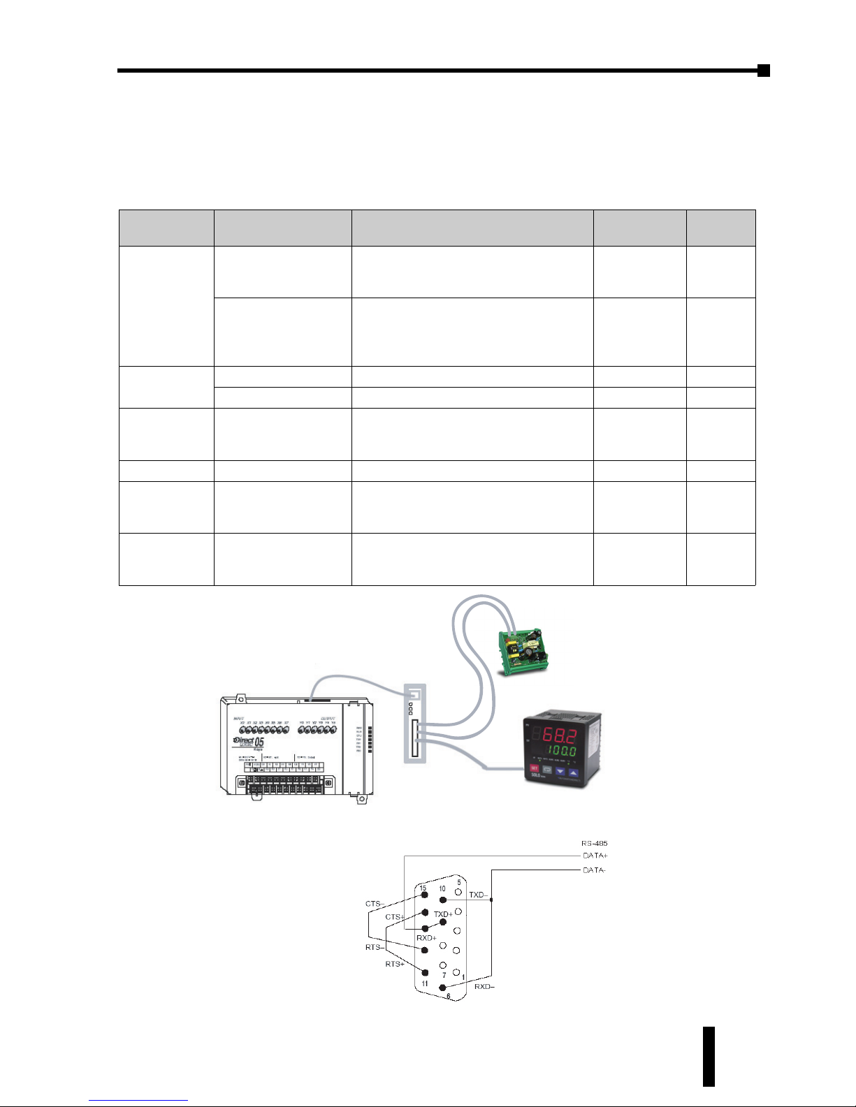
SOLO Temperature Controller User Manual
7–7
Connection with the DirectLOGIC PLC
The following DirectLOGIC PLCs can communicate with the SOLO controller. The
DL06 or D2-260 PLCs are preferred for connection with the SOLO controller
because they have a built in RS-485 communication port support function code 05.
Belden 8102/9841 RS422/485 cable
or equivalent
Solo controller
D0-DCM/D2-260/DL06 Port 2
Figure 2
You will need to make this
custom cable
Belden 8102/9841 RS422/485 cable
or equivalent
FA-ISOCON
SOLO controller
This cable is included
in the FA-ISCON
See Chapter 6 for wiring and setup
of the FA-ISOCON.
FA-24PS
+
-
Figure 1
DirectLogic
PLC
Com port Restriction
Instructions
to use
Wiring
Diagram
DL05 Port 2 + FA-ISOCON
Can’t write to the bit registers because
the DL05 does not support the
function code 05. Modbus RTU only
RX, WX Figure 1
D0-DCM Port2
Can’t write to the bit registers if
installed in the DL05 because the
DL05 does not support the function
code 05. Modbus RTU only.
RX, WX Figure 2
DL06
Port 2 Modbus RTU only MRX, MWX Figure 2
D0-DCM Port2 Modbus RTU only MRX, MWX Figure 2
D2-250-1 Port 2 + FA-ISOCON
+FA-15HD
Can’t write to the bit registers because
the D2-250-1 does not support the
function code 05.
RX, WX Figure 3
D2-260 Port 2
Modbus RTU only
MRX, MWX Figure 2
D3-350 Port 2 + FA-ISOCON Can’t write to the bit registers because
the D3-350 does not support the
function code 05. Modbus RTU only.
RX, WX Figure 4
D4-450 Port 1 + FA-ISOCON
Can’t write to the bit registers because
the D4-450 does not support the
function code 05. Modbus RTU only.
RX, WX Figure 5
Chapter 7: Modbus Communication
1st Ed. Rev C 07/08
Page 80
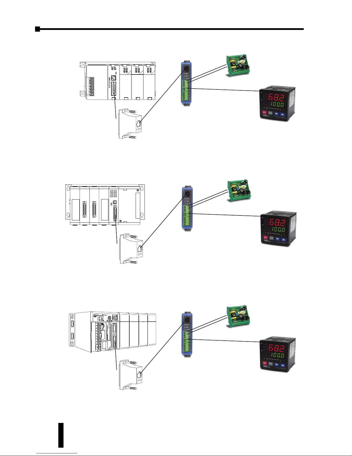
Chapter 7: Modbus Communication
SOLO Temperature Controller User Manual
7–8
D4-450 CPU
Connect 25-pin
connector to
D4-450 port 2
Universal 25-pin D-sub connector
(included with FA-ISOCON)
FA-ISOCON
Connect FA-ISOCON port A
to 25-pin connector’s RJ12 jack
using modular cable supplied with FA-ISOCON
SOLO controller
Connect FA-ISOCON port B to
Solo controller using Belden
8102/9841 RS422/485 cable
or equivalent
FA-24PS
+
-
Figure 5
D3-350 CPU
Connect 25-pin
connector to
D3-350 port 2
Universal 25-pin D-sub connector
(included with FA-ISOCON)
FA-ISOCON
Connect FA-ISOCON port A
to 25-pin connector’s RJ12 jack
using modular cable supplied with FA-ISOCON
SOLO controller
Connect FA-ISOCON port B to
Solo controller using Belden
8102/9841 RS422/485 cable
or equivalent
FA-24PS
+
-
Figure 4
D2-250-1 CPU
Connect FA-15HD
15-pin connector to
D2-250-1 port 2
FA-15HD
(order seperately)
FA-ISOCON
SOLO controller
Connect FA-ISOCON port A
to FA-15HD using RJ12 modular
cable supplied with FA-ISOCON
Connect FA-ISOCON port B to
Solo controller using Belden
8102/9841 RS422/485 cable
or equivalent
FA-24PS
+
-
Figure 3
Page 81
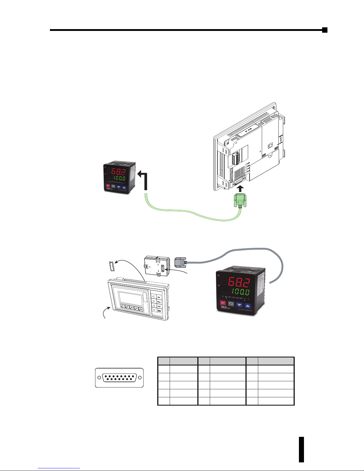
SOLO Temperature Controller User Manual
7–9
Connection with the C-more and C-more Micro HMI
panels
Any of the C-more and C-more Micro-Graphic HMI panels can be connected to
the SOLO controllers. The C-more HMI panels have a built in RS-485 port. The
C-more 3” Micro-Graphic panels require an optional module (EA-MG-SP1).
SOLO Controller
C-more
Touch Panel
Belden 8102/9841 RS422/485 cable
or equivalent
81
15 9
Pin Signal
1 Frame GND
TXD (232C)
RXD (232C)
Vcc
2
3
4
5 Logic GND
Pin Signal Pin Signal
6LE
CTS (232C)
RTS (232C)
RXD+ (422/485)
7
8
9
10 RXD– (422/485)
11 TXD+ (422/485)
TXD– (422/485)
Term. Resistor
do not use
12
13
14
15 do not use
Serial Communications
C-more and C-more Micro-Graphic Panel RS-485 port
C-more Micro-Graphic Panel
EA1-S3ML or EA1-S3ML-N
and 8 Button Keypad Bezel
EA-MG-BZ1
Expansion
Connector
EA-MG-SP1
Belden 8102/9841 RS422/485 cable
or equivalent
SOLO Controller
Chapter 7: Modbus Communication
1st Ed. Rev C 07/08
Page 82

Page 83
APPENDIX
APPENDIX
APPENDIX
MODBUS ADDRESS
MAP FOR RAMP /
SOAK CONTROL
In This Appendix...
Last Step Number . . . . . . . . . . . . . . . . . . . . . . . . .A–2
Additional Cycles . . . . . . . . . . . . . . . . . . . . . . . . . .A–2
Next Pattern Number . . . . . . . . . . . . . . . . . . . . . .A–2
Ramp / Soak SV . . . . . . . . . . . . . . . . . . . . . . . . . . .A–3
Ramp / Soak Time . . . . . . . . . . . . . . . . . . . . . . . . .A–4
Page 84
Appendix: Modbus Address Map for Ramp / Soak Control
SOLO Temperature Controller User Manual
A–2
Last Step Number
(ID:
SPX
n, P3-21)
Additional Cycles
(ID:
CYC
n, P3-22)
Next Pattern Number
(ID:
lin
n, P3-23)
Pattern
Number
Hexadecimal Modbus Decimal
PLC Address
(Octal)
Pattern 0 1060 44193 V10140
Pattern 1 1061 44194 V10141
Pattern 2 1062 44195 V10142
Pattern 3 1063 44196 V10143
Pattern 4 1064 44197 V10144
Pattern 5 1065 44198 V10145
Pattern 6 1066 44199 V10146
Pattern 7 1067 44200 V10147
Pattern
Number
Hexadecimal Modbus Decimal
PLC Address
(Octal)
Pattern 0 1050 44177 V10120
Pattern 1 1051 44178 V10121
Pattern 2 1052 44179 V10122
Pattern 3 1053 44180 V10123
Pattern 4 1054 44181 V10124
Pattern 5 1055 44182 V10125
Pattern 6 1056 44183 V10126
Pattern 7 1057 44184 V10127
Pattern
Number
Hexadecimal Modbus Decimal
PLC Address
(Octal)
Pattern 0 1040 44161 V10100
Pattern 1 1041 44162 V10101
Pattern 2 1042 44163 V10102
Pattern 3 1043 44164 V10103
Pattern 4 1044 44165 V10104
Pattern 5 1045 44166 V10105
Pattern 6 1046 44167 V10106
Pattern 7 1047 44168 V10107
Page 85
SOLO Temperature Controller User Manual
A–3
Appendix: Modbus Address Map for Ramp / Soak Control
1st Ed. Rev C 07/08
Ramp / Soak SV
(ID: SPmn, P3-19)
Hexadecimal
Modbus Decimal
PLC Address (Octal)
Pattern 0 Pattern 1 Pattern 2 Pattern 3 Pattern 4 Pattern 5 Pattern 6 Pattern 7
Step 0 V20000 V20010 V20020 V20030 V20040 V20050 V20060 V20070
Step 1 V20001 V20011 V20021 V20031 V20041 V20051 V20061 V20071
Step 2 V20002 V20012 V20022 V20032 V20042 V20052 V20062 V20072
Step 3 V20003 V20013 V20023 V20033 V20043 V20053 V20063 V20073
Step 4 V20004 V20014 V20024 V20034 V20044 V20054 V20064 V20074
Step 5 V20005 V20015 V20025 V20035 V20045 V20055 V20065 V20075
Step 6 V20006 V20016 V20026 V20036 V20046 V20056 V20066 V20076
Step 7 V20007 V20017 V20027 V20037 V20047 V20057 V20067 V20077
Pattern 0 Pattern 1 Pattern 2 Pattern 3 Pattern 4 Pattern 5 Pattern 6 Pattern 7
Step 0 48193 48201 48209 48217 48225 48233 48241 48249
Step 1 48194 48202 48210 48218 48226 48234 48242 48250
Step 2 48195 48203 48211 48219 48227 48235 48243 48251
Step 3 48196 48204 48212 48220 48228 48236 48244 48252
Step 4 48197 48205 48213 48221 48229 48237 48245 48253
Step 5 48198 48206 48214 48222 48230 48238 48246 48254
Step 6 48199 48207 48215 48223 48231 48239 48247 48255
Step 7 48200 48208 48216 48224 48232 48240 48248 48256
Pattern 0 Pattern 1 Pattern 2 Pattern 3 Pattern 4 Pattern 5 Pattern 6 Pattern 7
Step 0 2000 2008 2010 2018 2020 2028 2030 2038
Step 1 2001 2009 2011 2019 2021 2029 2031 2039
Step 2 2002 200A 2012 201A 2022 202A 2032 203A
Step 3 2003 200B 2013 201B 2023 202B 2033 203B
Step 4 2004 200C 2014 201C 2024 202C 2034 203C
Step 5 2005 200D 2015 201D 2025 202D 2035 203D
Step 6 2006 200E 2016 201E 2026 202E 2036 203E
Step 7 2007 200F 2017 201F 2027 202F 2037 203F
Page 86
Appendix: Modbus Address Map for Ramp / Soak Control
SOLO Temperature Controller User Manual
A–4
Ramp / Soak Time
(ID: TImn, P3-20)
Hexadecimal
Modbus Decimal
PLC Address (Octal)
Pattern 0 Pattern 1 Pattern 2 Pattern 3 Pattern 4 Pattern 5 Pattern 6 Pattern 7
Step 0 V20200 V20210 V20220 V20230 V20240 V20250 V20260 V20270
Step 1 V20201 V20211 V20221 V20231 V20241 V20251 V20261 V20271
Step 2 V20202 V20212 V20222 V20232 V20242 V20252 V20262 V20272
Step 3 V20203 V20213 V20223 V20233 V20243 V20253 V20263 V20273
Step 4 V20204 V20214 V20224 V20234 V20244 V20254 V20264 V20274
Step 5 V20205 V20215 V20225 V20235 V20245 V20255 V20265 V20275
Step 6 V20206 V20216 V20226 V20236 V20246 V20256 V20266 V20276
Step 7 V20207 V20217 V20227 V20237 V20247 V20257 V20267 V20277
Pattern 0 Pattern 1 Pattern 2 Pattern 3 Pattern 4 Pattern 5 Pattern 6 Pattern 7
Step 0 48321 48329 48337 48345 48353 48361 48369 48377
Step 1 48322 48330 48338 48346 48354 48362 48370 48378
Step 2 48323 48331 48339 48347 48355 48363 48371 48379
Step 3 48324 48332 48340 48348 48356 48364 48372 48380
Step 4 48325 48333 48341 48349 48357 48365 48373 48381
Step 5 48326 48334 48342 48350 48358 48366 48374 48382
Step 6 48327 48335 48343 48351 48359 48367 48375 48383
Step 7 48328 48336 48344 48352 48360 48368 48376 48384
Pattern 0 Pattern 1 Pattern 2 Pattern 3 Pattern 4 Pattern 5 Pattern 6 Pattern 7
Step 0 2080 2088 2090 2098 20A0 20A8 20B0 20B8
Step 1 2081 2089 2091 2099 20A1 20A9 20B1 20B9
Step 2 2082 208A 2092 209A 20A2 20AA 20B2 20BA
Step 3 2083 208B 2093 209B 20A3 20AB 20B3 20BB
Step 4 2084 208C 2094 209C 20A4 20AC 20B4 20BC
Step 5 2085 208D 2095 209D 20A5 20AD 20B5 20BD
Step 6 2086 208E 2096 209E 20A6 20AE 20B6 20BE
Step 7 2087 208F 2097 209F 20A7 20AF 20B7 20BF
Page 87
A
Additional Cycles, 3–6, 3–19, 3–22, A–2
Alarm 1, 3–6, 3–15, 3–16, 3–20, 4–8
Alarm 1 High Limit, 3–5, 3–15
Alarm 1 Low Limit, 3–5, 3–16
Alarm 2, 3–6, 3–16, 3–20, 4–8
Alarm 2 High Limit, 3–5, 3–16
Alarm 2 Low Limit, 3–5, 3–16
Alarm 3, 3–6, 3–16, 3–20
Alarm 3 High Limit, 3–5, 3–16
Alarm 3 Low Limit, 3–5, 3–16
Ambient Conditions
Altitude, 2–2
Ambient Temperature Range, 2–2
IP Rating, 2–2
Relative Humidity, 2–2
Shock Resistance, 2–2
Storage Temperature Range, 2–2
Vibration Resistance, 2–2
Analog High Adjustment, 3–4, 3–13, 3–14,
4–5, 4–6, 4–7
Analog Low Adjustment, 3–4, 4–5, 4–6, 4–7
Auto Tuning, 3–2, 3–4, 3–7, 3–10, 5–3
B
Baud Rate, 3–6, 3–21, 7–2
Bit Length, 3–6, 3–21, 7–2
Bit Registers, 7–2, 7–6, 7–7
C
Com port Settings, 6–4
Configuration Window, 6–4
Connection with the C-more and C-more
Micro HMI panels, 7–9
Connection with the DirectLogic PLC, 7–7
Control Mode, 3–4, 3–5, 3–6, 3–18, 5–2, 5–3,
5–4, 5–5
Controller and Panel Cutout Dimensions
SL4824 Series, 2–4
SL4848 Series, 2–4
SL4896 Series, 2–5
SL9696 Series, 2–5
Cooling Hysteresis, 3–4, 3–11, 5–4
Current Input, 4–2
D
Data Registers, 7–2, 7–3, 7–4, 7–5
Dead Band, 3–4, 3–12, 5–4
Decimal Point Position, 3–5, 3–15
Derivative Time, 3–4, 3–9, 5–3
Down Button, 3–2, 3–3
i–1
Index
SOLO Temperature Controller User Manual
1st Ed. Rev C 07/08
INDEX
Page 88

E
Error Display Information, 5–5
Event Inputs
Event 1 Input, 4–3
Event 2 Input, 4–3
G
General Description, 1–3
H
Heating / Cooling, 3–4, 3–5, 3–6, 3–19, 3–20
Heating Hysteresis, 3–4, 3–10, 5–4
I
Initial Power up, 3–3
Initial Setting Parameters, 3–6, 3–17
Input Range High, 3–6, 3–17, 3–18
Input Range Low, 3–6, 3–18
Input Type, 3–6, 3–17, 4–2
Input Types
Analog, 4–2
Current Input, 4–2
Voltage Input, 4–2
Platinum RTD, 4–2
Thermocouple, 4–2
Installation Considerations, 2–2
Integral Offset, 3–4, 3–10, 5–3
Integral Time, 3–4, 3–9, 3–10, 5–3
K
Keypad Operation, 3–3
Function Buttons, 3–3
Down Button, 3–2, 3–3
Rotate Button, 3–2, 3–3
SET Button, 3–2, 3–3
Up Button, 3–2, 3–3
L
Last Step Number, 3–6, 3–19, 3–21, A–2
LED status indicators
°F, °C LED Indicators, 3–2
ALM1, ALM2, ALM3 LED Indicators, 3–2
AT LED Indicator, 3–2
OUT1, OUT2 LED Indicators, 3–2
Lock Mode, 3–5, 3–16
M
Manual Control, 5–5
Modbus Address Map, A–2, A–3, A–4
Modbus Protocol, 3–6, 3–20, 7–2
Model Number Explanation, 1–4
Mounting Instructions
SL4824 Series, 2–3
SL4848, SL4896, SL9696 Series, 2–3
N
Network Address, 3–6, 3–20, 3–21, 7–2
Next Pattern Number, 3–6, 3–19, 3–22, A–2
O
On / Off Control, 5–3
On-Line Configuration, 3–6, 3–20
Operation Mode Parameters, 3–5, 3–15
Output 1 Cooling Period, 3–4, 3–11, 4–5, 4–6,
4–7
Output 1 Heating Period, 3–4, 3–11, 4–5, 4–6,
4–7
Output 1 Level, 3–5, 3–13, 3–16, 4–4, 4–6,
4–7, 5–5
Output 2 Level, 3–5, 3–16, 4–4, 5–5
Output 2 Period, 3–4, 3–12, 4–5
Output Types
Current, 4–5
Linear Voltage, 4–6
Relay, 4–4
Voltage Pulse, 4–5
P
i–2
Index
SOLO Temperature Controller User Manual
Page 89

Parity, 3–6, 3–21, 7–2
PD Control Offset, 3–4, 3–10
PID Control, 5–2, 5–3, 5–4
PID Parameter Group, 3–4, 3–7, 3–8, 3–9,
3–10, 5–2
Proportion Band, 3–4, 3–8, 3–12
Proportion Band Coefficient, 3–4, 3–12
Proportional Band, 5–3
Proportional Band Coefficient, 5–3
PV Display, 3–2
PV Monitor, 6–6
PV Offset, 3–4, 3–13
Q
Quick Start Guide, 1–2, 1–3
R
Ramp / Soak Control, 5–4
Ramp / Soak Pattern, 3–6, 3–15, 3–18, 3–19,
3–21, 3–22, 5–4
Ramp / Soak SV, 3–6, 3–21, A–3
Ramp / Soak Time, 3–6, 3–21, A–4
Recorder Window, 6–7
Regulation Mode Parameters, 3–4, 3–7
Reset to Factory Default, 3–22
Rotate Button, 3–2, 3–3
RS-485, 6–2, 6–4, 7–2, 7–7, 7–9
Run / Stop, 3–5, 3–15
S
Safety Information, 2–6, 2–7
Serial Number Label Information
SL4824 Series, 1–4
SL4848, SL4896, and SL9696 Series, 1–4
SET Button, 3–2, 3–3
Software Installation, 6–3
Special Symbols
Notepad, 1–2
Warning, 1–2
Starting Ramp / Soak Pattern, 3–5, 3–15
Stop Bit, 3–6, 3–21, 7–2
SV Display, 3–2, 3–7
System Alarm, 3–6, 3–20, 4–8, 4–10
T
Target SV, 3–4, 3–7, 3–8, 3–9, 3–10
Technical Support, 1–2
Temperature Unit, 3–6
Terminal Identification
SL4824 Series, 2–8
SL4848 Series, 2–9
SL4896 Series, 2–10
SL9696 Series, 2–11
U
Unpacking, 1–3
Up Button, 3–2, 3–3
V
Voltage Input, 4–2
i–3
Index
SOLO Temperature Controller User Manual
1st Ed. Rev C 07/08
Page 90

 Loading...