

Page 1
WARNING: To minimize the risk of potential safety problems, you should
follow all applicable local and national codes that regulate the installation
and operation of your equipment. These codes vary from area to area and
it is your responsibility to determine which codes should be followed, and to
verify that the equipment, installation, and operation are in compliance with
the latest revision of these codes.
Equipment damage or serious injury to personnel can result from the
failure to follow all applicable codes and standards. We do not guarantee
the products described in this publication are suitable for your particular
application, nor do we assume any responsibility for your product design,
installation, or operation.
If you have any questions concerning the installation or operation of
this equipment, or if you need additional information, please call Technical
Support at 770-844-4200.
This publication is based on information that was available at the time
it was printed. At AutomationDirect.com® we constantly strive to improve
our products and services, so we reserve the right to make changes to
the products and/or publications at any time without notice and without
any obligation. This publication may also discuss features that may not be
available in certain revisions of the product.
Removable Terminal Block Specifications
Part Number P2-RTB P2-RTB-1
Number of
positions
Wire Range
Conductors “USE COPPER CONDUCTORS, 75ºC” or equivalent.
Screw Driver
Width
Screw Size M2 N/A
Screw Torque 2.5 lb·in (0.28 N·m) N/A
18 Screw Terminals 18 Spring Clamp Terminals
30–16 AWG (0.051 – 1.31 mm²)
Solid / Stranded Conductor
3/64 in (1.2 mm) Insulation Maximum
1/4 in (6 – 7 mm) Strip Length
1/8 in (3.8 mm) Maximum
28–16 AWG (0.081 – 1.31 mm²)
Solid / Stranded Conductor
3/64 in (1.2 mm) Insulation Maximum
19/64 in (7 – 8 mm) Strip Length
Sales 800-633-0405 www.productivity2000.com
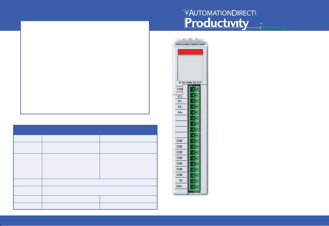
P2-04DAL-2
2000
P2-04DAL-2 Analog Output
The P2-04DAL-2 Low Resolution Voltage Output
Module provides four channels for converting
a digital value of 0 to 4095 (12-bit) to 0-10VDC
analog signals for use with the Productivity2000
System.
Warning .................................. 1
Removable Terminal Block Specifications. . . . . . . . 1
General Specifications ...................... 2
Output Specifications ....................... 2
Wiring Diagram and Schematic ................ 3
Module Installation Procedure ................. 4
QR Code ................................. 4
Hot Swap Information ....................... 4
Wiring Options ............................. 5
Module Configuration ....................... 5
Linear Scaling ............................. 6
Non-Linear Scaling ......................... 6
Terminal Block sold separately, (see wiring options on page 5).
Warranty: Thirty-day money-back guarantee. Two-year limited
replacement. (See www.productivity2000.com for details).
1
Page 2
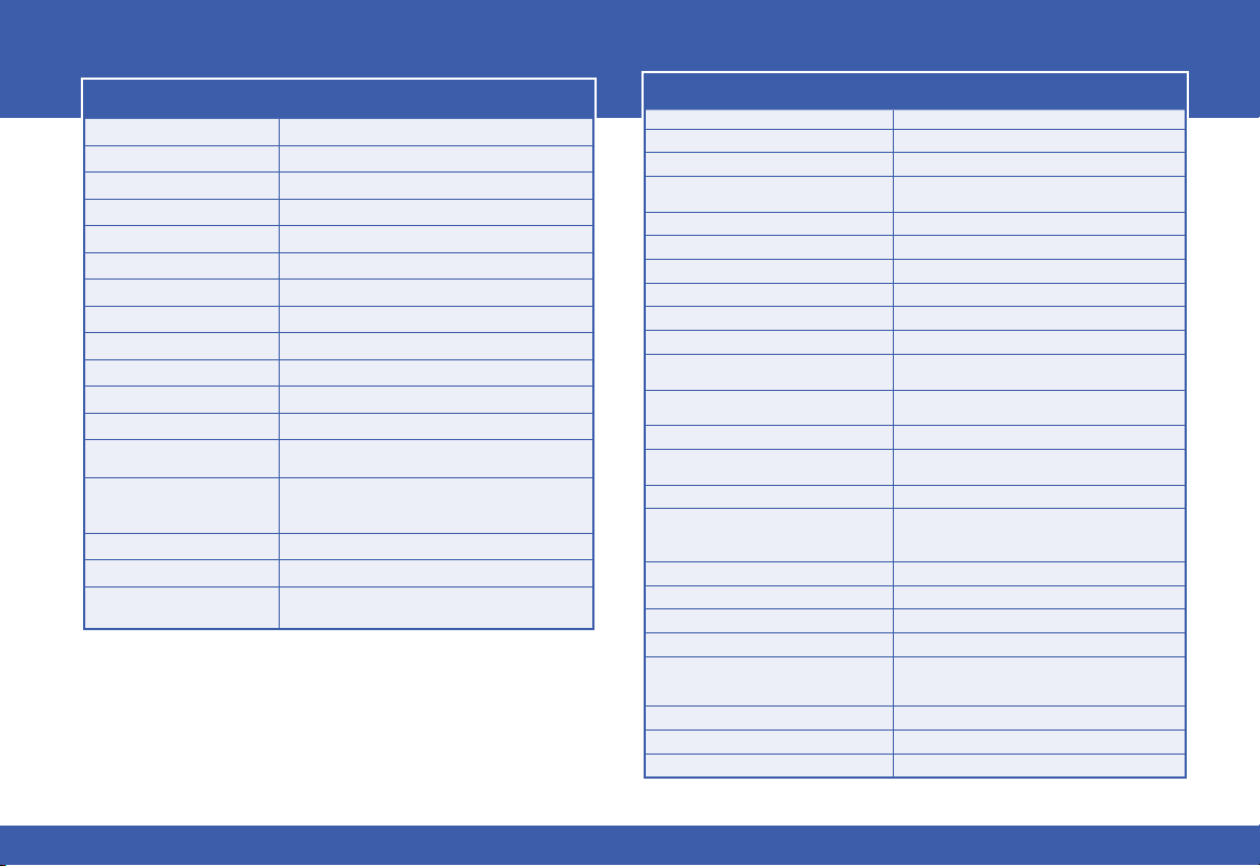
General Specifications
Operating Temperature 0º to 60ºC (32º to 140ºF)
Storage Temperature -20º to 70ºC (-4º to 158ºF)
Humidity 5 to 95% (non-condensing)
Environmental Air No corrosive gases permitted
Vibration IEC60068-2-6 (Test Fc)
Shock IEC60068-2-27 (Test Ea)
Field to Logic Side Isolation 1800VAC applied for 1 second
Insulation Resistance > 10MΩ @ 500VDC
Heat Dissipation 3250mW
Enclosure Type Open Equipment
Module Keying to Backplane Electronic
Module Location Any I/O slot in a Productivity2000 System
Field Wiring
EU Directive
Connector Type (sold separately) 18-position removable terminal block
Weight 95g (3.4 oz)
Agency Approvals
*Meets EMC and Safety requirements. See the D.O.C. for details.
Removable terminal block. Optional ZIPLink wiring
system See “Wiring Options” on page 5.
See the “EU Directive” topic in the Productivity Suite
Help File. Information can also be obtained at:
www.productivity2000.com
UL61010-2-201 File E139594, Canada & USA
CE (EMC: EN61131-2*, SAFETY: EN61010-2-201)
Output Specifications
Output Channels 4
Output Range 0-10 V
Signal Resolution 12-bit
Resolution Value of LSB
(least significant bit)
Data Range 0 to 4095 counts
Output Type Voltage sourcing at 10mA
Output Value in Fault Mode 0V
Load Impedance ≥1000Ω
Maximum Capacitive Load 0.01 µF
Allowed Load Type Grounded
Maximum Inaccuracy
Maximum Full Scale Calibration Error
(Not Including Offset)
Maximum Offset Calibration Error ±0.2% of range maximum
Accuracy vs. Temperature
Max Crosstalk -72dB, 1 LSB
Linearity Error (End to End)
Output Stability and Repeatability ±2% LSB after 10 min. warm up (typical)
Output Ripple ±0.1% of full scale
Output Settling Time 0.300 µs max., 5µs min. (full scale range)
All Channel Update Rate 1ms
Maximum Continuous Overload
Type of Output Protection 0.1 µF Transient Suppressor
Output Signal at Power Up and Power Down 0V
External Power Supply Required 24VDC (-20% / +25%), 60mA
0-10 V = 2.44 mV per count
1 LSB = 1 count
0.5% of range
(Including temperature drift)
±0.2% of range maximum
±75 PPM / °C maximum full-scale calibration change
(±0.0025% of range / °C)
±4 LSB maximum, (±0.1% of full scale)
Monotonic with no missing codes
Outputs current limited to 40mA typical
Continuous overloads on multiple outputs can damage
the module.
2
Tech Support 770-844-4200www.productivity2000.com
Page 3
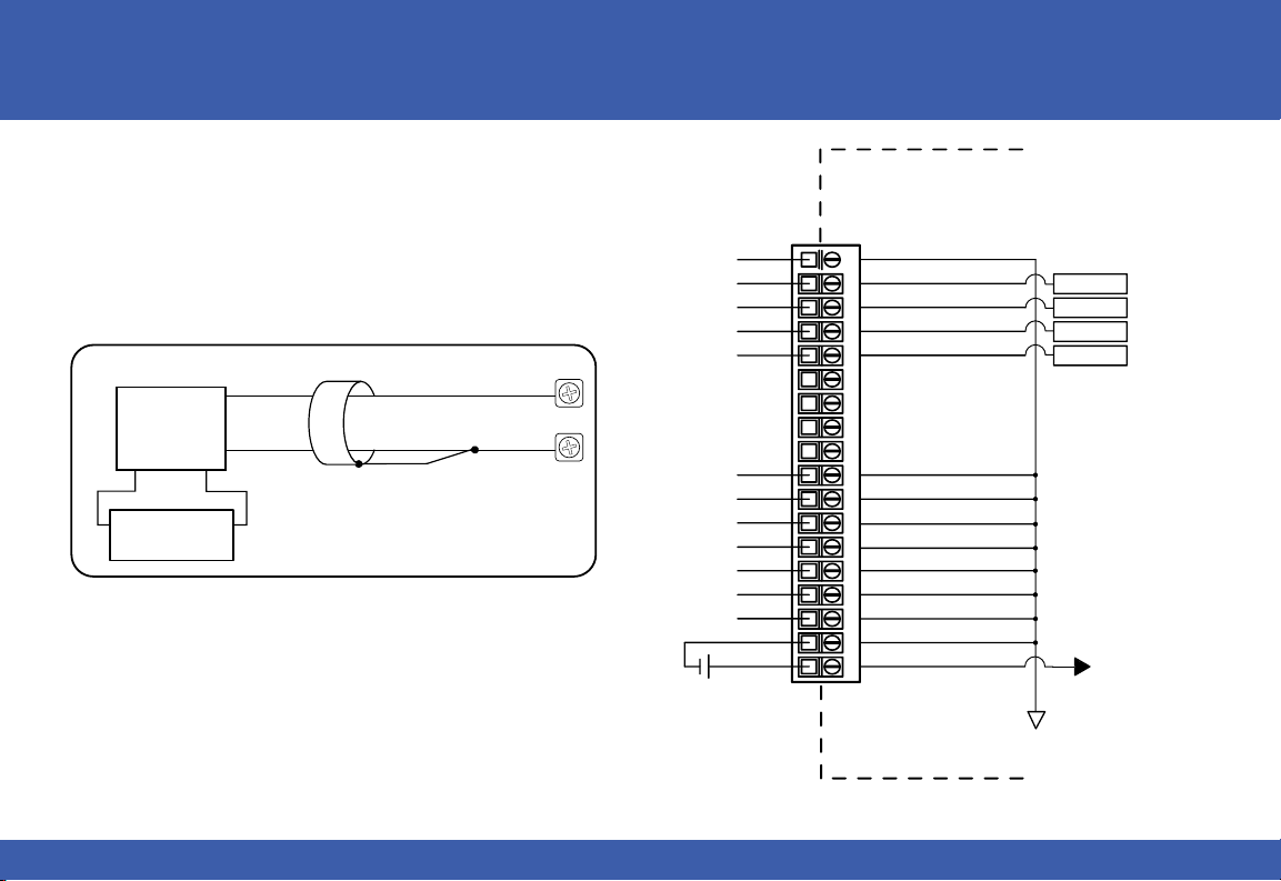
Wiring Diagram Schematic
Supplie
Voltage Output Circuits
V+
0 - 10
VDC Load
Load
Power Supply
COM
- +
24VDC User
dPower
COM
V1+
V2+
V3+
V4+
COM
COM
COM
COM
COM
COM
COM
0V
24V+
INTERNAL
MODULE CIRCUITRY
1 2 3 4 5 6 7 8 9
voltage source
voltage source
voltage source
voltage source
10 11 12 1813 14 15 1 617
ISOLATED ANALOG
CIRCUIT COMMON
CH1 DAC
CH2 DAC
CH3 DAC
CH4 DAC
ISOLATED ANALOG
CIRCUIT POWER
Sales 800-633-0405 www.productivity2000.com
3
Page 4
1 Align
with slot
2 rotate
to seated
position
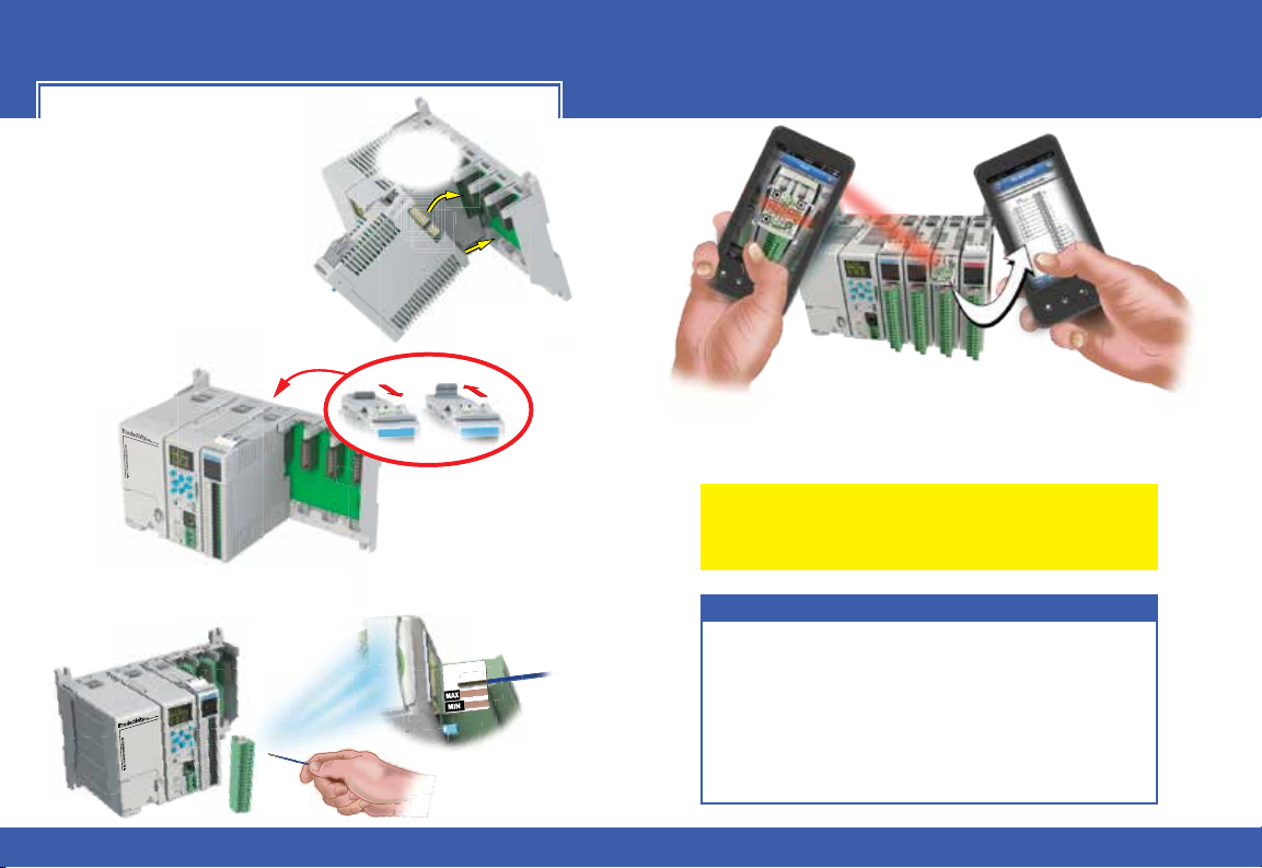
Module Installation
WIRE STRIP
LENGTH
WIRE STRIP
LENGTH
Locked
Unlocked
WARNING: Do not apply field power until
the following steps are completed. See
hot-swapping procedure for
exceptions.
Step One: Align module
catch with base slot and
rotate module into
connector.
Step Two: Pull top locking
tab toward module face. Click
indicates lock is
engaged.
Step Three: Attach field wiring using the removable
terminal block or ZIPLink wiring
system.
QR Code
Use any QR Code reader application to
display the module’s product insert.
Caution: If possible, remove field power prior to
proceeding. If not, then EXTREME care MUST be taken
to prevent damage to the module, or even personal injury
due to a short circuit from the live terminal block.
Important Hot-Swap Information
The Productivity2000 supports hot-swap! Individual
modules can be taken offline, removed, and replaced
while the rest of the system continues controlling your
process. Before attempting to use the hot-swap feature,
be sure to read the hot-swap topic in the programming
software’s help file or our online documentation at
AutomationDirect.com for details on how to plan your
installation for use of this powerful feature.
4
Tech Support 770-844-4200www.productivity2000.com
Page 5
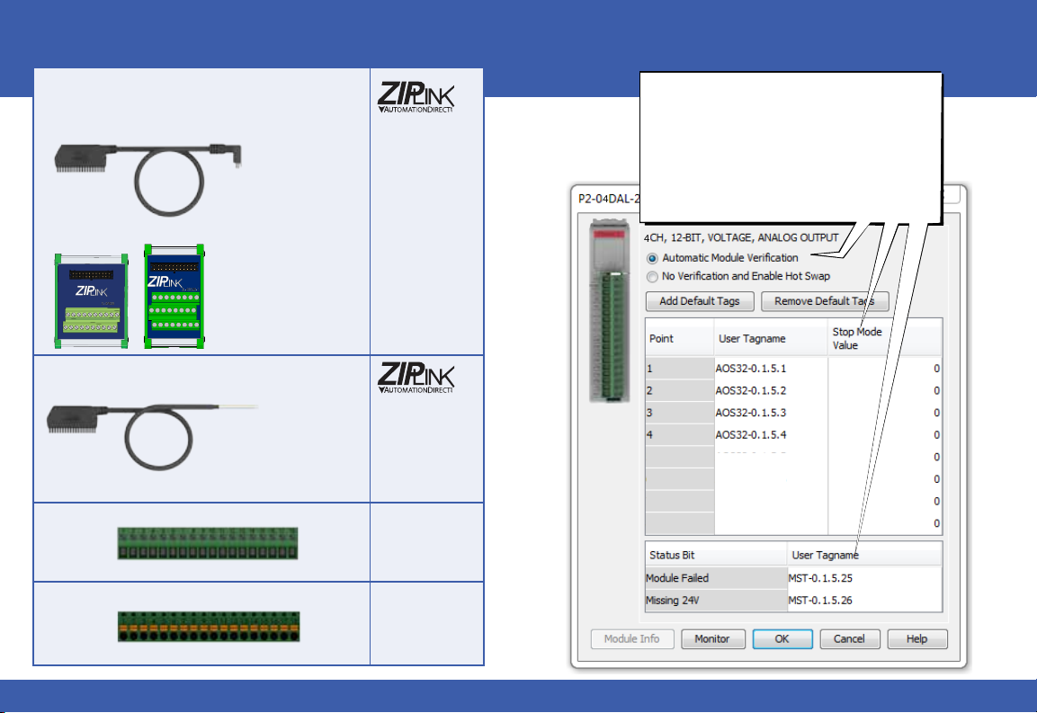
Wiring Options
1ZIPLink Connection System
Cable + ZIPLink Module = Complete System
ZIPLink pre-wired
terminal block cables
0.5m (1.6FT) cable
1.0m (3.3FT) cable
2.0m (6.6FT) cable
ZL-P2-CBL18
ZL-P2-CBL18-1
ZL-P2-CBL18-2
Module Configuration
Using the Hardware Configuration tool in the
Productivity Suite programming software, drag
and drop the P2-04DAL-2 module into the base
configuration.
Select Automatic Module Verification or No
Verification and Enable Hot Swap. If desired,
assign a User Tagname to each output point
(channel) selected and to each Status Bit Item.
4
A Stop Mode Value may also be assigned.
Terminal Block with pigtail cable
2
Screw Terminal Block only
3
Press Terminal Block only
4
Sales 800-633-0405 www.productivity2000.com
ZIPLink Modules
Feed through
1.0m (3.3FT) cable
2.0m (6.6FT) cable
4
ZL-RTB20
ZL-RTB20-1
ZL-P2-CBL18-1P
ZL-P2-CBL18-2P
P2-RTB
(Quantity 1)
P2-RTB-1
(Quantity 1)
5
Page 6
rT
7
0
00000
0
Linear Scaling Non-Linear Scaling
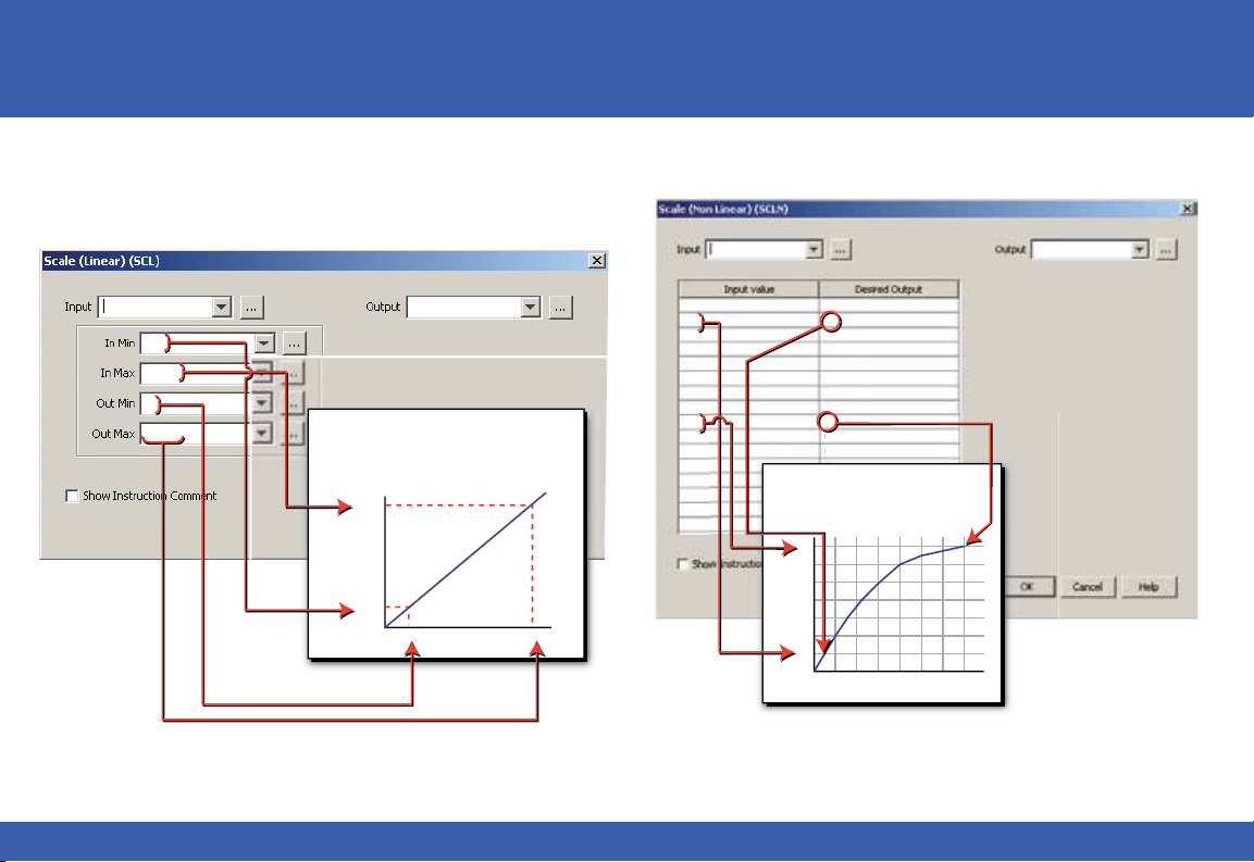
The Scale (Linear) function can be used to:
• Convert analog field input signals from the range which is native to the
analog input module to an application specific range.
• Make other linear conversions in ranges appropriate to the application.
Tank Level
220
12500
0
4095
Select the Input and Output tags appropriate
for the application. Convert raw input signals
to engineering units for use in the program, or
convert engineering units to output signals for
control purposes
Control Valve
max
min
min max
The Scale (Non-Linear) function can be used for Non-Linear applications.
Level Transmitte
0
1
2
3
4
5
6
6.5
7
0
0
0
0
0
0
0
0
.5
1
1.55
2.25
3
4
5
7
0
0
0
Enter values for each breakpoint in the
0
table. Each breakpoint will define a
0
segment of the non-linear scaling.
0
0
7
6
5
4
3
2
1
0
1 2 3 4 5 6 7
ank Level
6
Tech Support 770-844-4200www.productivity2000.com
Page 7

Sales 800-633-0405 www.productivity2000.com
7
Page 8
Document Name Edition/Revision Date
P2-04DAL-2-DS 1st Ed. 8/22/2016
Copyright 2016, AutomationDirect.com Incorporated/All Rights Reserved Worldwide
8
Tech Support 770-844-4200www.productivity2000.com
 Loading...