

Page 1
1
2
3
4
5
6
7
8
9
10
11
12
13
14
15
16
C2
C1
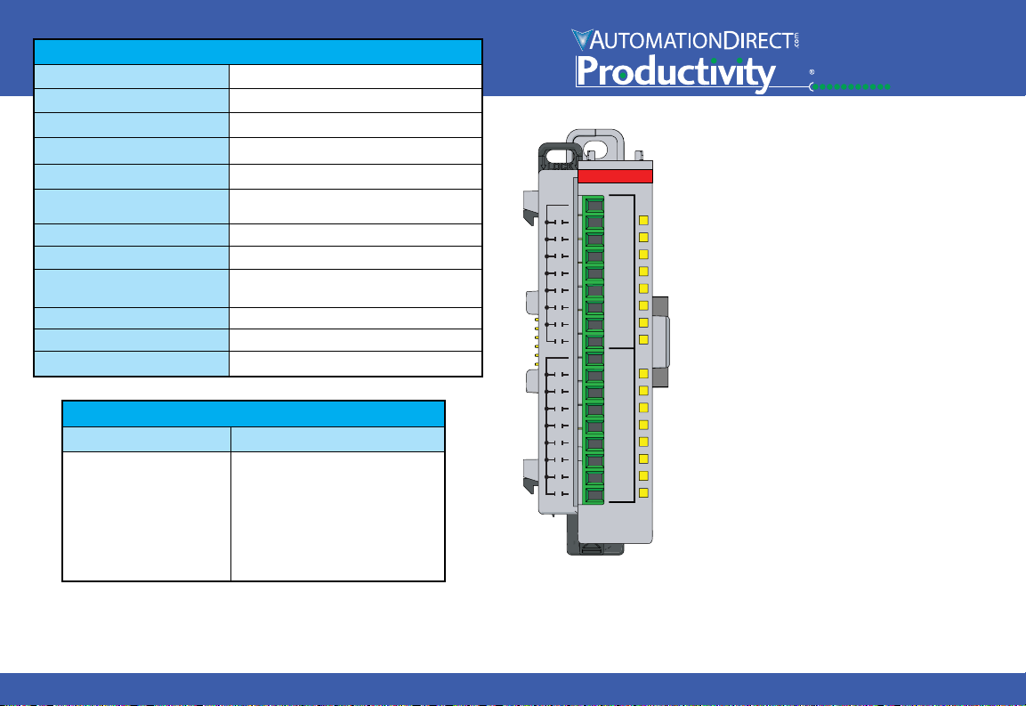
P1-16TR
RELAY
OUTPUT
Output
.1
Module
.2
QR
.2
Wiring
.3
Schematic
.3
General
.4
Te
.4
Wa
.4
T
Wa
replacement (See www
Outputs per Module
Rated Voltage
Operating Voltage Range
Output Type
AC Frequency
Maximum Output Current
Minimum Load Current
Maximum Inrush Current
OFF to ON, ON to OFF
Response
Status Indicators
Commons
Maximum Applicable Fuse
Voltage & Type of Load Operations at 1A Load Current
30VDC Resistive
30VDC Solenoid
120VAC Resistive
120VAC Solenoid
240VAC Resistive
240VAC Solenoid
Output Specifications
16
6.25–30 VDC, 6–120 VAC
5–30 VDC, 5–144 VAC
Relay FORM A (SPST)
47–63 Hz
2A / point, 8A / common for both AC and DC
2A / point, 4A / common if used with ZIPLink Cable
5mA @ 5VDC
5A for 10ms
10 ms
Logic Side (16 points)
2 isolated (8 points/common)
8A
Typical Relay Life
100,000
100,000
100,000
100,000
100,000
100,000
P1-16TR Relay Output
The P1-16TR Relay Output Module provides
sixteen 2A outputs with two isolated commons
for use with the Productivity1000 system.
Code . . . . . . . . . . . . . . . . . . . . . . . . . . . . . . . . . . .
rminal Block Specifications . . . . . . . . . . . . . . . . . . .
rning . . . . . . . . . . . . . . . . . . . . . . . . . . . . . . . . . . . .
erminal Block sold separately, (see wiring options on page 3).
rranty: Thirty-day money-back guarantee. Two-year limited
1000
Specifications . . . . . . . . . . . . . . . . . . . . . . . . .
Installation . . . . . . . . . . . . . . . . . . . . . . . . . . .
Options . . . . . . . . . . . . . . . . . . . . . . . . . . . . . . .
& Wiring Diagram . . . . . . . . . . . . . . . . . . .
Specifications . . . . . . . . . . . . . . . . . . . . . . . .
.productivity1000.com for details).
Sales 800-633-0405 www.productivity1000.com
1
Page 2
QR Code
1 2 3 4 5 6 7 8 9
10
L
L
L
L
L
L
L
L
24V
1
2
3
4
0V
5
6
7
8
12 - 24VDC
+ -
+ -
1 2 3 4 5 6 7 8 9
10
L
L
L
L
L
L
L
L
24V
1
2
3
4
0V
5
6
7
8
12 - 24VDC
+ -
Dual Power Source
Single Power Source
3.3 - 24VDC
P1-08TD1 Wiring Diagram
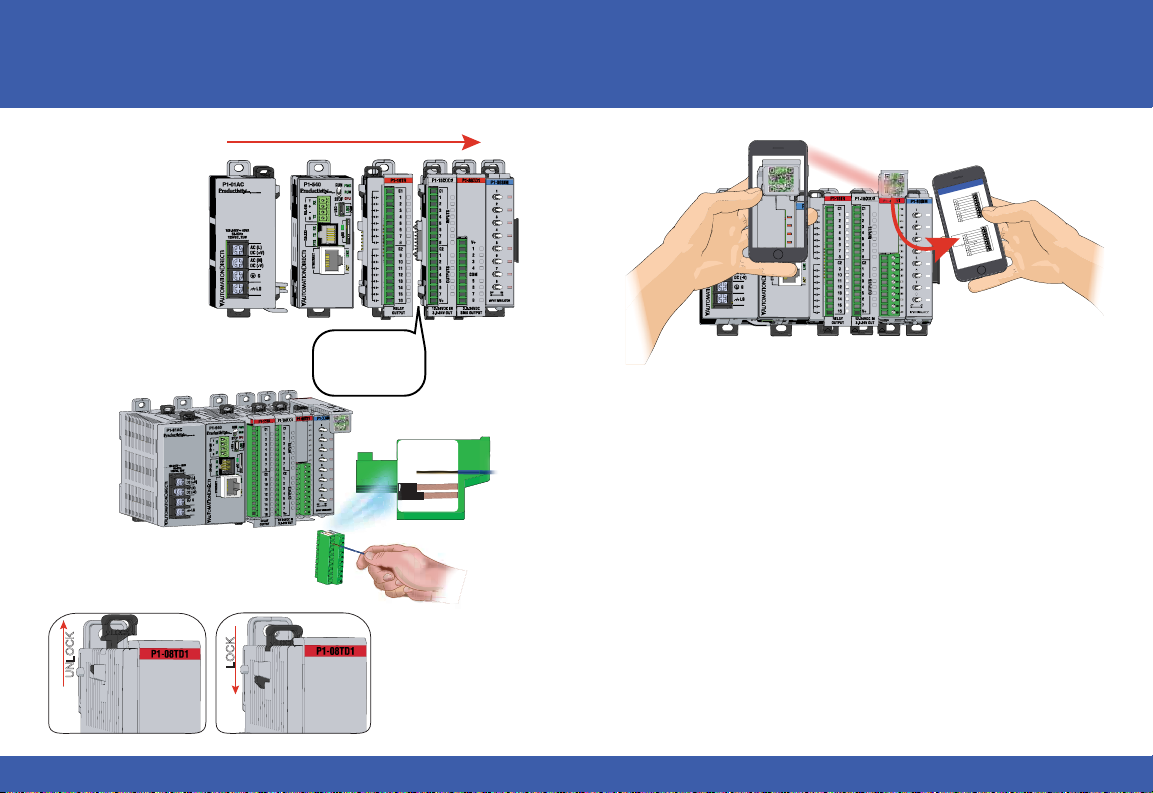
Module Installation
WARNING: Do not add or remove modules with
field power applied.
Step One: With latch
in “locked” position, align
connectors on the side of
each module and stack
by pressing together.
Click indicates lock is
engaged.
Step Two: Attach field wiring using
the removable terminal block or ZIPLink
wiring system.
Step Three: To unstack modules, pull
locking latch up into the unlocked position
and then pull modules apart.
UNLOCK
P1-08TD1
P1-08TD1
Check all latches are
secure after modules
are connected.
P1-08TD1
MAX
MIN
WIRE STRIP
LENGTH
Use any QR Code reader application to
display the module’s product insert.
LOCK
2
Tech Support 770-844-4200www.productivity1000.com
Page 3
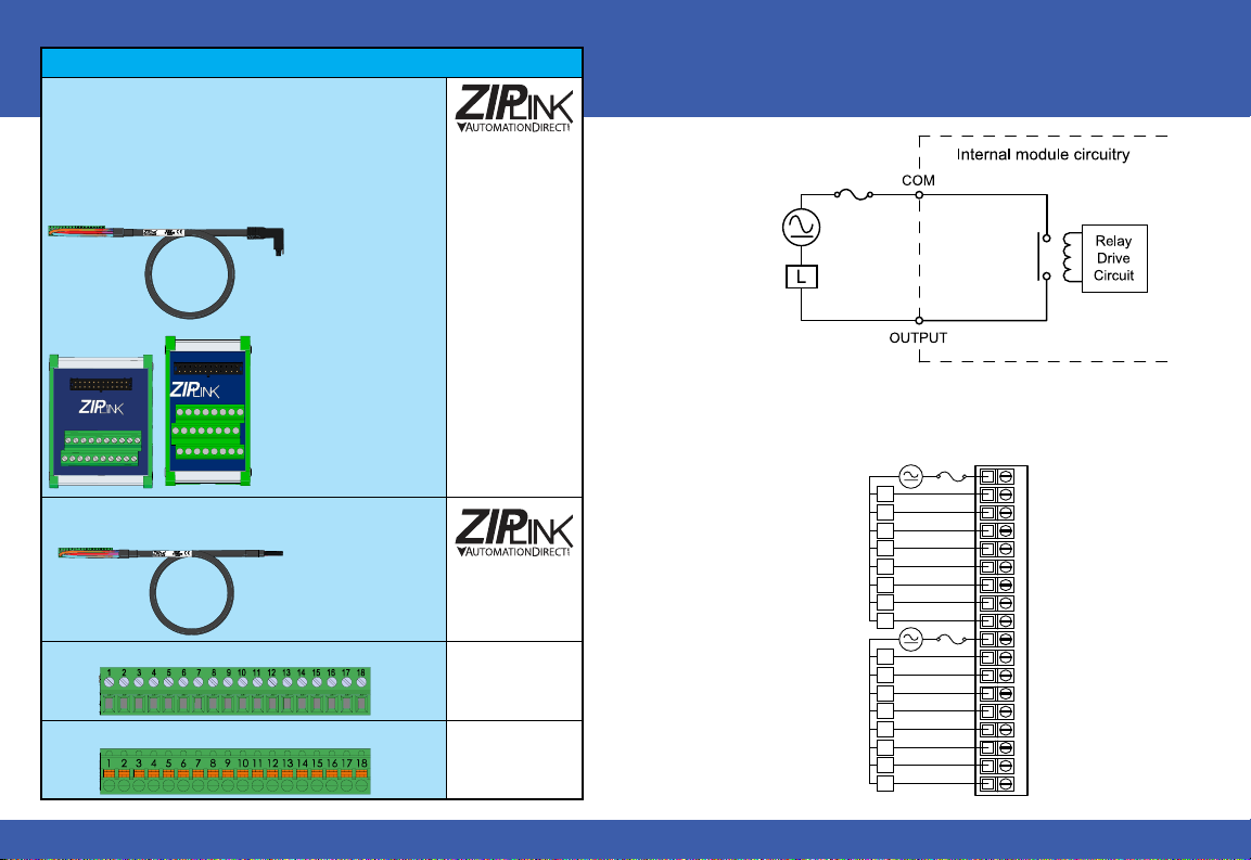
Wiring Options
P1-16TR Schematic and Wiring Diagram
21
1ZIPLink Connection System
Cable + ZIP
Link Module = Complete System
ZIP
Link pre-wired
terminal block
cables
6–24 VDC
6–120 VAC
50–60 Hz
User Supplied
External Fuse
8A Max
ZL-RTB20-1
ZL-RTB20
ZIP
Terminal Block with pigtail cable
2
Screw Terminal Block only
3
Spring Clamp Terminal Block only
4
Sales 800-633-0405 www.productivity1000.com
0.5 m (1.6 ft)
cable
1.0 m (3.3 ft)
cable
2.0 m (6.6 ft)
cable
Link Modules
Feed through
1.0 m (3.3 ft)
cable
2.0 m (6.6 ft)
cable
ZL-P1-CBL18
ZL-P1-CBL18-1
ZL-P1-CBL18-2
ZL-RTB20
ZL-RTB20-1
ZL-P1-CBL18-1P
ZL-P1-CBL18-2P
P2-RTB
(Quantity 1)
P2-RTB-1
(Quantity 1)
6–24 VDC
6–120 VAC
50–60 Hz
6–24 VDC
6–120 VAC
50–60 Hz
EXTERNAL
RECOMMENDED
8A Max
L
L
L
L
L
L
L
L
L
L
L
L
L
L
L
L
FUSE
12345678910111
813 14 15 16 17
C1
1
2
3
4
5
6
7
8
C2
9
10
11
12
13
14
15
16
3
Page 4
WARNING: To minimize the risk of potential safety problems, you should
follow all applicable local and national codes that regulate the installation
and operation of your equipment. These codes vary from area to area and
it is your responsibility to determine which codes should be followed, and
to verify that the equipment, installation, and operation are in compliance
with the latest revision of these codes.
Equipment damage or serious injury to personnel can result from
the failure to follow all applicable codes and standards. We do not
guarantee the products described in this publication are suitable for
your particular application, nor do we assume any responsibility for your
product design, installation, or operation.
If you have any questions concerning the installation or operation of
this equipment, or if you need additional information, please call Technical
Support at 770-844-4200.
This publication is based on information that was available at the time
it was printed. At AutomationDirect.com
our products and services, so we reserve the right to make changes to
the products and/or publications at any time without notice and without
any obligation. This publication may also discuss features that may not be
available in certain revisions of the product.
®
we constantly strive to improve
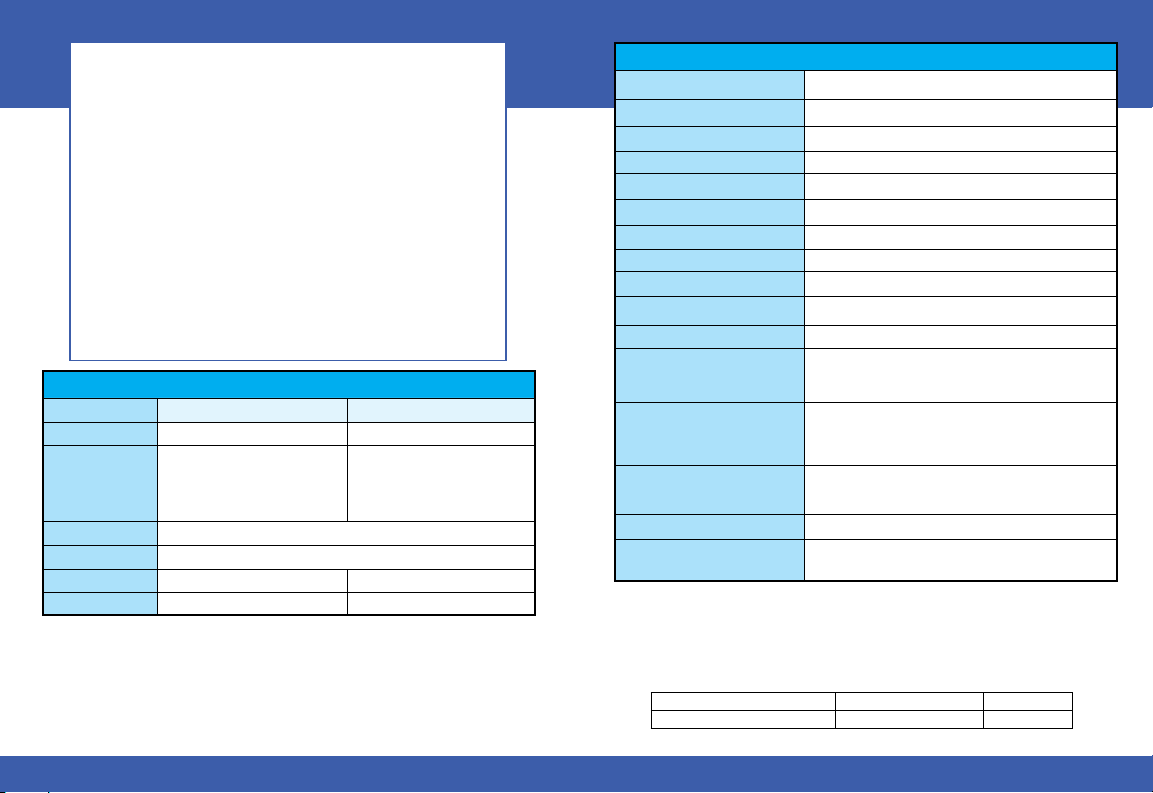
Terminal Block Specifications
Part Number
Positions
Wire Range
Conductors
Screw Driver
Screw Size
Screw Torque
*Recommended Screw Driver TW-SD-MSL-1
P2-RTB P2-RTB-1
18 Screw Terminals 18 Spring Clamp Terminals
30–16 AWG (0.051–1.31 mm²)
Solid / Stranded Conductor
3/64 in (1.2 mm) Insulation Max.
1/4 in (6–7 mm) Strip Length
“USE COPPER CONDUCTORS, 75ºC” or equivalent.
0.1 in (2.5 mm) Maximum*
M2 N/A
2.5 lb·in (0.28 N·m) N/A
28–16 AWG (0.081–1.31 mm²)
Solid / Stranded Conductor
3/64 in (1.2 mm) Insulation Max.
19/64 in (7–8 mm) Strip Length
General Specifications
Operating Temperature
Storage Temperature
Humidity
Environmental Air
Vibration
Shock
Field Circuit Isolation
Insulation Resistance
Heat Dissipation
Enclosure Type
Module Location
Field Wiring
EU Directive
Connector Type
(sold separately)
Weight
Agency Approvals
*See CE Declaration of Conformance for details.
0° to 60°C (32° to 140°F)
-20° to 70°C (-4° to 158°F)
5 to 95% (non-condensing)
No corrosive gases permitted
IEC60068-2-6 (Test Fc)
IEC60068-2-27 (Test Ea)
1800VAC applied for 1 second
>10MΩ @ 500VDC
3000mW
Open Equipment
Any I/O position in a Productivity1000 System.
Use ZIPLink Wiring System or removable terminal block
(sold separately). See “Wiring Options” on page 3.
See the “EU Directive” topic in the Productivity Suite
Help File. Information can also be obtained at:
www.productivity1000.com
18 Position Removable Terminal Block
91g (3.2 oz)
UL 61010-2-201 file E139594, Canada & USA
CE (EN61131-2 EMC and EN61010-2-201 Safety)*
Document Name Edition/Revision Date
P1-16TR-DS 2nd Edition 2/13/2018
Copyright 2018, AutomationDirect.com Incorporated/All Rights Reserved Worldwide
4
Tech Support 770-844-4200www.productivity1000.com
 Loading...