

Page 1

OP-640
Operator Panel
Manual Number OP-640-M
Page 2

WARNING
Thank you for purchasing automation equipment from Automationdirect.comä. We want your new DirectLOGICä
automation equipment to operate safely. Anyone who installs or uses this equipment should read this publication (and
any other relevant publications) before installing or operating the equipment.
To minimize the risk of potential safety problems, you should follow all applicable local and nationalcodes that regulate
the installation and operation of your equipment. These codes vary from area to area and usually change with time. It is
your responsibility to determine which codes should be followed, and to verify that the equipment, installation, and
operation is in compliance with the latest revision of these codes.
At a minimum, you should follow all applicable sections of the National Fire Code, National Electrical Code, and the
codes of the National Electrical Manufacturer’s Association (NEMA). There may be local regulatory or government
offices that can also help determine which codes and standards are necessary for safe installation and operation.
Equipment damage or serious injury to personnel can result from the failure to follow all applicable codes and
standards. We do not guarantee the products described in this publication are suitable for your particular application,
nor do we assume any responsibility for your product design, installation, or operation.
If you have any questions concerning the installation or operation of this equipment, or if you need additional
information, please call us at 1--800--633--0405.
This publication is based on information that was available at the time it was printed. At Automationdirect.comä we
constantly strive to improve our products and services, so we reserve the right to make changes to the products and/or
publications at any time without notice and without any obligation. This publication may also discuss features that may
not be available in certain revisions of the product.
Trademarks
This publication may contain references to products produced and/or offered by other companies. The product and
company names may be trademarked and are the sole property of their respective owners. Automationdirect.comä
disclaims any proprietary interest in the marks and names of others.
Copyright 1999, Automationdirect.comä Incorporated
All Rights Reserved
No part of this manual shall be copied, reproduced, or transmitted in any way without the prior, written consent of
Automationdirect.comä Incorporated. Automationdirect.comä retains the exclusive rights to all information
included in this document.
Page 3
1
M
a
n
u
a
l
R
e
v
i
s
i
o
n
s
If you contact us in reference to this manual, be sure and include the revision number.
Title: OP--640 Operator Panel User Manual
Manual Number: OP--640--M
Issue Date Effective Pages Description of Changes
Original 9/99 All Original Issue
Page 4

1
E
U
I
n
f
o
r
m
a
tio
n
This product is manufactured in compliance with European Union (EU) Directives and carries the CE
ExternalFus
e
mark. The following information is provided to comply with EU documentation requirements.
NOTE: Products with CE marks perform their required functions safely and adhere
to relevant standards as specified by EU directives provided they are used
according to their intended purpose and that the instructions in this manual are
adhered to. The protection provided by the equipment may be impaired if this
equipment is used in a manner not specified in this manual. Only replacement parts
supplied by PLCDirect or its agents should be used. A listingof international affiliates
is available at our Web site http://www.plcdirect.com
Technical Support
SELV Circuits
Environmental
Specifications
Preventative
Maintenance and
Cleaning
Protection
for Input Power
If you need technical assistance, please call the technical support group at
PLCDirect (3505 Hutchinson Rd., Cumming, GA 30040, U.S.A.) at 800--633--0405.
They are available Monday through Friday from 9:00 A.M. to 6:00 P.M. Eastern
Standard Time. Their Web Site address is http://www.plcdirect.com
All electrical circuits connected to the communications port receptacle are rated as
Safety Extra Low Voltage (SELV).
Operating Temperature 0° to 50° C. . . . . . . . . . . . . . . . . . . . .
Storage Temperature --20° to 70° C. . . . . . . . . . . . . . . . . . . . . .
Operating Humidity 95% (non-condensing). . . . . . . . . . . . . . . . . . . . . . . .
Air Composition No corrosive gases permitted. . . . . . . . . . . . . . . . . . . . . . . . . . .
No preventative maintenance is required. To clean the exterior of the panel
disconnect the input power and carefully wipe the panel with a cloth moistened with
plain water.
There are no internal fuses for the input power circuits, so external circuit protection
is needed to ensure the safety of service personnel and the safe operation of the
equipment itself. To comply with EU specifications, the input power must be fused.
Use a fuse rated at twice the input current rating of the panel. For example, if the
panel has an input current rating of 0.5 amperes, use a fuse rated for 1 ampere.
Page 5

1
i
Table of Contents
Chapter 1: Getting Started
Introduction 1--2. . . . . . . . . . . . . . . . . . . . . . . . . . . . . . . . . . . . . . . . . . . . . . . . . . . . . . . . . . . . . . . . . . . . . . . . .
The Purpose of this Manual 1--2. . . . . . . . . . . . . . . . . . . . . . . . . . . . . . . . . . . . . . . . . . . . . . . . . . . . . . . . .
SupplementalManuals 1--2. . . . . . . . . . . . . . . . . . . . . . . . . . . . . . . . . . . . . . . . . . . . . . . . . . . . . . . . . . . . .
Technical Support 1--2. . . . . . . . . . . . . . . . . . . . . . . . . . . . . . . . . . . . . . . . . . . . . . . . . . . . . . . . . . . . . . . . .
Chapters 1--3. . . . . . . . . . . . . . . . . . . . . . . . . . . . . . . . . . . . . . . . . . . . . . . . . . . . . . . . . . . . . . . . . . . . . . . . .
Appendices 1--3. . . . . . . . . . . . . . . . . . . . . . . . . . . . . . . . . . . . . . . . . . . . . . . . . . . . . . . . . . . . . . . . . . . . . . .
Conventions Used 1--3. . . . . . . . . . . . . . . . . . . . . . . . . . . . . . . . . . . . . . . . . . . . . . . . . . . . . . . . . . . . . . . . . . .
Key Topics for Each Chapter 1--3. . . . . . . . . . . . . . . . . . . . . . . . . . . . . . . . . . . . . . . . . . . . . . . . . . . . . . . .
OP--640 Overview 1--4. . . . . . . . . . . . . . . . . . . . . . . . . . . . . . . . . . . . . . . . . . . . . . . . . . . . . . . . . . . . . . . . . . .
Plan your System 1--4. . . . . . . . . . . . . . . . . . . . . . . . . . . . . . . . . . . . . . . . . . . . . . . . . . . . . . . . . . . . . . . . .
General Panel Information 1--4. . . . . . . . . . . . . . . . . . . . . . . . . . . . . . . . . . . . . . . . . . . . . . . . . . . . . . . . . .
LCD Display Window 1--4. . . . . . . . . . . . . . . . . . . . . . . . . . . . . . . . . . . . . . . . . . . . . . . . . . . . . . . . . . . . . .
Pushbuttons 1--5. . . . . . . . . . . . . . . . . . . . . . . . . . . . . . . . . . . . . . . . . . . . . . . . . . . . . . . . . . . . . . . . . . . . . .
Annunciator Lamps 1--5. . . . . . . . . . . . . . . . . . . . . . . . . . . . . . . . . . . . . . . . . . . . . . . . . . . . . . . . . . . . . . . .
Back-Panel Layout 1--5. . . . . . . . . . . . . . . . . . . . . . . . . . . . . . . . . . . . . . . . . . . . . . . . . . . . . . . . . . . . . . . .
Serial Communications Port 1--5. . . . . . . . . . . . . . . . . . . . . . . . . . . . . . . . . . . . . . . . . . . . . . . . . . . . . . . .
Power Receptacle 1--5. . . . . . . . . . . . . . . . . . . . . . . . . . . . . . . . . . . . . . . . . . . . . . . . . . . . . . . . . . . . . . . . .
RUN/PGM and 1--5. . . . . . . . . . . . . . . . . . . . . . . . . . . . . . . . . . . . . . . . . . . . . . . . . . . . . . . . . . . . . . . . . . . .
TERM Switches 1--5. . . . . . . . . . . . . . . . . . . . . . . . . . . . . . . . . . . . . . . . . . . . . . . . . . . . . . . . . . . . . . . . . . .
Frequently Asked Questions 1--6. . . . . . . . . . . . . . . . . . . . . . . . . . . . . . . . . . . . . . . . . . . . . . . . . . . . . . . . .
Chapter 2: Installation and Specifications
Connecting a Power Supply 2--2. . . . . . . . . . . . . . . . . . . . . . . . . . . . . . . . . . . . . . . . . . . . . . . . . . . . . . . . . .
Power Supply Connections 2--2. . . . . . . . . . . . . . . . . . . . . . . . . . . . . . . . . . . . . . . . . . . . . . . . . . . . . . . . .
Multi-panel Power Supply Connection 2--2. . . . . . . . . . . . . . . . . . . . . . . . . . . . . . . . . . . . . . . . . . . . . . . .
Preparing the Panel for Configuration 2--3. . . . . . . . . . . . . . . . . . . . . . . . . . . . . . . . . . . . . . . . . . . . . . . . .
RUN/PGM Switch 2--3. . . . . . . . . . . . . . . . . . . . . . . . . . . . . . . . . . . . . . . . . . . . . . . . . . . . . . . . . . . . . . . . .
Configuration Cable 2--3. . . . . . . . . . . . . . . . . . . . . . . . . . . . . . . . . . . . . . . . . . . . . . . . . . . . . . . . . . . . . . .
Preparing the Panel for Communications 2--4. . . . . . . . . . . . . . . . . . . . . . . . . . . . . . . . . . . . . . . . . . . . .
RUN/PGM Switch 2--4. . . . . . . . . . . . . . . . . . . . . . . . . . . . . . . . . . . . . . . . . . . . . . . . . . . . . . . . . . . . . . . . .
OP--9001 Multi-Panel Configurations 2--4. . . . . . . . . . . . . . . . . . . . . . . . . . . . . . . . . . . . . . . . . . . . . . . . . .
The TERM Switch 2--4. . . . . . . . . . . . . . . . . . . . . . . . . . . . . . . . . . . . . . . . . . . . . . . . . . . . . . . . . . . . . . . . .
Connecting Cable Details 2--6. . . . . . . . . . . . . . . . . . . . . . . . . . . . . . . . . . . . . . . . . . . . . . . . . . . . . . . . . . . .
Connecting Cable 2--6. . . . . . . . . . . . . . . . . . . . . . . . . . . . . . . . . . . . . . . . . . . . . . . . . . . . . . . . . . . . . . . . .
Labeling the Lamps and Pushbuttons 2--7. . . . . . . . . . . . . . . . . . . . . . . . . . . . . . . . . . . . . . . . . . . . . . . . .
Labeling the Lamps and Pushbuttons 2--7. . . . . . . . . . . . . . . . . . . . . . . . . . . . . . . . . . . . . . . . . . . . . . . .
Creating the Labels 2--7. . . . . . . . . . . . . . . . . . . . . . . . . . . . . . . . . . . . . . . . . . . . . . . . . . . . . . . . . . . . . . . .
Creating Labels Using OP--WINEDIT 2--7. . . . . . . . . . . . . . . . . . . . . . . . . . . . . . . . . . . . . . . . . . . . . . . .
Templates for Manually Creating Labels 2--9. . . . . . . . . . . . . . . . . . . . . . . . . . . . . . . . . . . . . . . . . . . . . . .
Dimensions for Mounting 2--10. . . . . . . . . . . . . . . . . . . . . . . . . . . . . . . . . . . . . . . . . . . . . . . . . . . . . . . . . . . .
Panel Specifications 2--11. . . . . . . . . . . . . . . . . . . . . . . . . . . . . . . . . . . . . . . . . . . . . . . . . . . . . . . . . . . . . . . . .
Page 6

i
i
Table of Contents
Physical Specifications 2--11. . . . . . . . . . . . . . . . . . . . . . . . . . . . . . . . . . . . . . . . . . . . . . . . . . . . . . . . . . . . .
Environmental Specifications 2--11. . . . . . . . . . . . . . . . . . . . . . . . . . . . . . . . . . . . . . . . . . . . . . . . . . . . . . .
Operating Specifications 2--11. . . . . . . . . . . . . . . . . . . . . . . . . . . . . . . . . . . . . . . . . . . . . . . . . . . . . . . . . . .
Chapter 3: Understanding the Features
Learning the Features 3--2. . . . . . . . . . . . . . . . . . . . . . . . . . . . . . . . . . . . . . . . . . . . . . . . . . . . . . . . . . . . . . .
Status and Control Registers 3--3. . . . . . . . . . . . . . . . . . . . . . . . . . . . . . . . . . . . . . . . . . . . . . . . . . . . . . . . .
Status and Control Register Overview 3--3. . . . . . . . . . . . . . . . . . . . . . . . . . . . . . . . . . . . . . . . . . . . . . . .
Bit Level Access 3--3. . . . . . . . . . . . . . . . . . . . . . . . . . . . . . . . . . . . . . . . . . . . . . . . . . . . . . . . . . . . . . . . . .
Register Definition 3--4. . . . . . . . . . . . . . . . . . . . . . . . . . . . . . . . . . . . . . . . . . . . . . . . . . . . . . . . . . . . . . . . .
Status and Control Register Definition 3--4. . . . . . . . . . . . . . . . . . . . . . . . . . . . . . . . . . . . . . . . . . . . . . . .
Messages 3--5. . . . . . . . . . . . . . . . . . . . . . . . . . . . . . . . . . . . . . . . . . . . . . . . . . . . . . . . . . . . . . . . . . . . . . . . . . .
Displaying Messages on the LCD Screen 3--5. . . . . . . . . . . . . . . . . . . . . . . . . . . . . . . . . . . . . . . . . . . . .
Static Messages 3--5. . . . . . . . . . . . . . . . . . . . . . . . . . . . . . . . . . . . . . . . . . . . . . . . . . . . . . . . . . . . . . . . . .
Dynamic Messages 3--5. . . . . . . . . . . . . . . . . . . . . . . . . . . . . . . . . . . . . . . . . . . . . . . . . . . . . . . . . . . . . . . .
Displaying Messages 3--6. . . . . . . . . . . . . . . . . . . . . . . . . . . . . . . . . . . . . . . . . . . . . . . . . . . . . . . . . . . . . . . .
Static Message Operation 3--6. . . . . . . . . . . . . . . . . . . . . . . . . . . . . . . . . . . . . . . . . . . . . . . . . . . . . . . . . .
Static Display 3--6. . . . . . . . . . . . . . . . . . . . . . . . . . . . . . . . . . . . . . . . . . . . . . . . . . . . . . . . . . . . . . . . . . . . .
Dynamic Message Operation 3--7. . . . . . . . . . . . . . . . . . . . . . . . . . . . . . . . . . . . . . . . . . . . . . . . . . . . . . .
Dynamic MessageTop Line 3--8. . . . . . . . . . . . . . . . . . . . . . . . . . . . . . . . . . . . . . . . . . . . . . . . . . . . . . . . .
Dynamic Message Bottom Line 3--8. . . . . . . . . . . . . . . . . . . . . . . . . . . . . . . . . . . . . . . . . . . . . . . . . . . . .
Displaying Data With a Decimal Point 3--9. . . . . . . . . . . . . . . . . . . . . . . . . . . . . . . . . . . . . . . . . . . . . . . .
Displaying BCD and Binary Numbers 3--9. . . . . . . . . . . . . . . . . . . . . . . . . . . . . . . . . . . . . . . . . . . . . . . .
Displaying BCD Double Numbers 3--9. . . . . . . . . . . . . . . . . . . . . . . . . . . . . . . . . . . . . . . . . . . . . . . . . . .
Displaying Floating Point Numbers 3--10. . . . . . . . . . . . . . . . . . . . . . . . . . . . . . . . . . . . . . . . . . . . . . . . . .
Pushbuttons and Lamps 3--11. . . . . . . . . . . . . . . . . . . . . . . . . . . . . . . . . . . . . . . . . . . . . . . . . . . . . . . . . . . . .
Pushbutton Operation 3--11. . . . . . . . . . . . . . . . . . . . . . . . . . . . . . . . . . . . . . . . . . . . . . . . . . . . . . . . . . . . . .
Pushbutton Example 3--11. . . . . . . . . . . . . . . . . . . . . . . . . . . . . . . . . . . . . . . . . . . . . . . . . . . . . . . . . . . . . . .
Pushbuttons Using Direct Access to Status Register Bits 3--12. . . . . . . . . . . . . . . . . . . . . . . . . . . . . . .
Pushbutton LEDs 3--12. . . . . . . . . . . . . . . . . . . . . . . . . . . . . . . . . . . . . . . . . . . . . . . . . . . . . . . . . . . . . . . . .
Lamp Example 3--12. . . . . . . . . . . . . . . . . . . . . . . . . . . . . . . . . . . . . . . . . . . . . . . . . . . . . . . . . . . . . . . . . . . .
Lamp Flash 3--13. . . . . . . . . . . . . . . . . . . . . . . . . . . . . . . . . . . . . . . . . . . . . . . . . . . . . . . . . . . . . . . . . . . . . . .
Memory Mapping Process 3--13. . . . . . . . . . . . . . . . . . . . . . . . . . . . . . . . . . . . . . . . . . . . . . . . . . . . . . . . . . .
OP Base Register Memory Definition 3--13. . . . . . . . . . . . . . . . . . . . . . . . . . . . . . . . . . . . . . . . . . . . . . . .
Operator Panel Base Memory 3--13. . . . . . . . . . . . . . . . . . . . . . . . . . . . . . . . . . . . . . . . . . . . . . . . . . . . . .
Mapping Operation 3--16. . . . . . . . . . . . . . . . . . . . . . . . . . . . . . . . . . . . . . . . . . . . . . . . . . . . . . . . . . . . . . . . . .
Mapping Examples (DL05, 105, DL205, D3--350, and DL405) 3--16. . . . . . . . . . . . . . . . . . . . . . . . . . . .
Mapping the Status Register 3--16. . . . . . . . . . . . . . . . . . . . . . . . . . . . . . . . . . . . . . . . . . . . . . . . . . . . . . . .
Mapping the Control Register 3--17. . . . . . . . . . . . . . . . . . . . . . . . . . . . . . . . . . . . . . . . . . . . . . . . . . . . . . .
Mapping Example (D3--330/340) 3--17. . . . . . . . . . . . . . . . . . . . . . . . . . . . . . . . . . . . . . . . . . . . . . . . . . . . . .
Mapping the Status Register 3--17. . . . . . . . . . . . . . . . . . . . . . . . . . . . . . . . . . . . . . . . . . . . . . . . . . . . . . . .
Mapping the Control Register 3--18. . . . . . . . . . . . . . . . . . . . . . . . . . . . . . . . . . . . . . . . . . . . . . . . . . . . . . .
Chapter 4: Configuring Your Operator Panel
Preparing for Configuration 4--2. . . . . . . . . . . . . . . . . . . . . . . . . . . . . . . . . . . . . . . . . . . . . . . . . . . . . . . . . .
OP--WINEDIT Software 4--2. . . . . . . . . . . . . . . . . . . . . . . . . . . . . . . . . . . . . . . . . . . . . . . . . . . . . . . . . . . .
More about OP--WINEDIT 4--2. . . . . . . . . . . . . . . . . . . . . . . . . . . . . . . . . . . . . . . . . . . . . . . . . . . . . . . . . .
HELP Screens 4--2. . . . . . . . . . . . . . . . . . . . . . . . . . . . . . . . . . . . . . . . . . . . . . . . . . . . . . . . . . . . . . . . . . . .
Page 7

iii
Table of Contents
Application Worksheets 4--3. . . . . . . . . . . . . . . . . . . . . . . . . . . . . . . . . . . . . . . . . . . . . . . . . . . . . . . . . . . .
Computer System Requirements 4--3. . . . . . . . . . . . . . . . . . . . . . . . . . . . . . . . . . . . . . . . . . . . . . . . . . . .
How to Configure Your Panel 4--3. . . . . . . . . . . . . . . . . . . . . . . . . . . . . . . . . . . . . . . . . . . . . . . . . . . . . . . . .
Step 1 4--3. . . . . . . . . . . . . . . . . . . . . . . . . . . . . . . . . . . . . . . . . . . . . . . . . . . . . . . . . . . . . . . . . . . . . . . . . . .
Step 2 4--3. . . . . . . . . . . . . . . . . . . . . . . . . . . . . . . . . . . . . . . . . . . . . . . . . . . . . . . . . . . . . . . . . . . . . . . . . . .
Step 3 4--4. . . . . . . . . . . . . . . . . . . . . . . . . . . . . . . . . . . . . . . . . . . . . . . . . . . . . . . . . . . . . . . . . . . . . . . . . . .
Step 4 4--4. . . . . . . . . . . . . . . . . . . . . . . . . . . . . . . . . . . . . . . . . . . . . . . . . . . . . . . . . . . . . . . . . . . . . . . . . . .
Step 5 4--4. . . . . . . . . . . . . . . . . . . . . . . . . . . . . . . . . . . . . . . . . . . . . . . . . . . . . . . . . . . . . . . . . . . . . . . . . . .
Step 6 4--5. . . . . . . . . . . . . . . . . . . . . . . . . . . . . . . . . . . . . . . . . . . . . . . . . . . . . . . . . . . . . . . . . . . . . . . . . . .
Step 7 4--6. . . . . . . . . . . . . . . . . . . . . . . . . . . . . . . . . . . . . . . . . . . . . . . . . . . . . . . . . . . . . . . . . . . . . . . . . . .
Step 8 4--6. . . . . . . . . . . . . . . . . . . . . . . . . . . . . . . . . . . . . . . . . . . . . . . . . . . . . . . . . . . . . . . . . . . . . . . . . . .
Chapter 5: Programming Examples
Examples Using DirectLOGIC PLCs 5--2. . . . . . . . . . . . . . . . . . . . . . . . . . . . . . . . . . . . . . . . . . . . . . . . . . .
Register Usage 5--2. . . . . . . . . . . . . . . . . . . . . . . . . . . . . . . . . . . . . . . . . . . . . . . . . . . . . . . . . . . . . . . . . . .
DL05, DL105, DL205, D3--350 and DL405 Examples 5--3. . . . . . . . . . . . . . . . . . . . . . . . . . . . . . . . . . . .
Defining the Status Register 5--3. . . . . . . . . . . . . . . . . . . . . . . . . . . . . . . . . . . . . . . . . . . . . . . . . . . . . . . .
Using a Function Button 5--5. . . . . . . . . . . . . . . . . . . . . . . . . . . . . . . . . . . . . . . . . . . . . . . . . . . . . . . . . . . .
Lighting a Lamp 5--6. . . . . . . . . . . . . . . . . . . . . . . . . . . . . . . . . . . . . . . . . . . . . . . . . . . . . . . . . . . . . . . . . . .
Flashing a Lamp 5--6. . . . . . . . . . . . . . . . . . . . . . . . . . . . . . . . . . . . . . . . . . . . . . . . . . . . . . . . . . . . . . . . . .
Displaying Messages 5--7. . . . . . . . . . . . . . . . . . . . . . . . . . . . . . . . . . . . . . . . . . . . . . . . . . . . . . . . . . . . . .
Displaying Binary Numbers 5--8. . . . . . . . . . . . . . . . . . . . . . . . . . . . . . . . . . . . . . . . . . . . . . . . . . . . . . . . .
Displaying BCD Double Numbers 5--9. . . . . . . . . . . . . . . . . . . . . . . . . . . . . . . . . . . . . . . . . . . . . . . . . . .
Displaying Floating Point Numbers Example 1 5--10. . . . . . . . . . . . . . . . . . . . . . . . . . . . . . . . . . . . . . . .
Displaying Floating Point Numbers Example 2 5--11. . . . . . . . . . . . . . . . . . . . . . . . . . . . . . . . . . . . . . . .
Example Using D3--330/340 5--12. . . . . . . . . . . . . . . . . . . . . . . . . . . . . . . . . . . . . . . . . . . . . . . . . . . . . . . . . .
Example 5--12. . . . . . . . . . . . . . . . . . . . . . . . . . . . . . . . . . . . . . . . . . . . . . . . . . . . . . . . . . . . . . . . . . . . . . . . .
Allen-Bradley SLC 5/03 & 5/04 and Micrologix Examples 5--13. . . . . . . . . . . . . . . . . . . . . . . . . . . . . . .
Interfacing to A-B Memory 5--13. . . . . . . . . . . . . . . . . . . . . . . . . . . . . . . . . . . . . . . . . . . . . . . . . . . . . . . . . .
Lighting a Lamp 5--13. . . . . . . . . . . . . . . . . . . . . . . . . . . . . . . . . . . . . . . . . . . . . . . . . . . . . . . . . . . . . . . . . . .
Flashing a Lamp 5--14. . . . . . . . . . . . . . . . . . . . . . . . . . . . . . . . . . . . . . . . . . . . . . . . . . . . . . . . . . . . . . . . . .
Using a Function Button 5--14. . . . . . . . . . . . . . . . . . . . . . . . . . . . . . . . . . . . . . . . . . . . . . . . . . . . . . . . . . . .
Displaying Messages 5--15. . . . . . . . . . . . . . . . . . . . . . . . . . . . . . . . . . . . . . . . . . . . . . . . . . . . . . . . . . . . . .
Displaying Messages Example 5--16. . . . . . . . . . . . . . . . . . . . . . . . . . . . . . . . . . . . . . . . . . . . . . . . . . . . . .
Displaying Binary Numbers 5--17. . . . . . . . . . . . . . . . . . . . . . . . . . . . . . . . . . . . . . . . . . . . . . . . . . . . . . . . .
Chapter 6: Troubleshooting
Troubleshooting the OP--640 Panel 6--2. . . . . . . . . . . . . . . . . . . . . . . . . . . . . . . . . . . . . . . . . . . . . . . . . . .
Troubleshooting 6--2. . . . . . . . . . . . . . . . . . . . . . . . . . . . . . . . . . . . . . . . . . . . . . . . . . . . . . . . . . . . . . . . . . .
Panel Configuration Problems 6--2. . . . . . . . . . . . . . . . . . . . . . . . . . . . . . . . . . . . . . . . . . . . . . . . . . . . . .
Panel to PLC Communications Problems 6--3. . . . . . . . . . . . . . . . . . . . . . . . . . . . . . . . . . . . . . . . . . . . .
Allen-Bradley Panel to PLC Communications Problems 6--4. . . . . . . . . . . . . . . . . . . . . . . . . . . . . . . .
Appendix A: Worksheets
Application Worksheets Example A--2. . . . . . . . . . . . . . . . . . . . . . . . . . . . . . . . . . . . . . . . . . . . . . . . . . . .
Application Worksheets Form A--2. . . . . . . . . . . . . . . . . . . . . . . . . . . . . . . . . . . . . . . . . . . . . . . . . . . . . . .
Index
Page 8

1
1
Getting Started
In This Chapter. . . .
— Introduction
— Conventions Used
— OP-640 Overview
— Frequently Asked Questions
Page 9
GettingStarte
d
1--
2
Getting Started
Introduction
The Purpose of
this Manual
Supplemental
Manuals
Thank you for purchasing an OP--640
OptiMate panel. This User Manual
shows you how to install, configure, and
program the OP--640. Also included are
application examples. Be sure to keep
this manual handy for reference when
you run into questions. If you understand
PLC systems and operator interface
units, this manual will provide all the
information that you need to get and keep
your panel up and running.
Reference the appropriate PLC/CPU
user manuals for the commands and
address references required for your
system. If you are using a DirectLOGIC
PLC product, you will want to keep the
DirectSOFT User Manual handy while
programming your system. For other
PLC brands you must reference their
user manuals to properly program the
ladder logic required to operate the
OP-panel.
How to
Use the
OP-640
The OP-1500 and OP-1510
Operator panels may be
reconfigured to exchange data
with your programmable
controller.
The OP-1500 and OP-1510
Operator panels may be
reconfigured to exchange data
with your programmable
controller.
The OP-1500 and OP-1510
Operator panels may be
reconfigured to exchange data
with your programmable
controller.
The OP-1500 and OP-1510
Operator panels may be
reconfigured to exchange data
with your programmable
controller.
The OP-1500 and OP-1510
Operator panels may be
reconfigured to exchange data
with your programmable
controller.
Technical Support
We realize that even though we strive to be the best, we may have arranged our
information in such a way that you cannot find what you are looking for. First, check
these resources for help in locating the information:
S Table of Contents -- chapter and section listing of contents, in the front
of this manual
S Index -- located at the end ot this manual
S Appendices -- reference material for key topics, near the end of this
manual
You can also check our online resources for the latest product support information:
S Internet -- the address of our Web site is www.automationdirect.com
If you still need assistance, please call us at 1--770--844--4200. Our technical
support group will be glad to work with you in answering your questions. They are
available Monday through Friday from 9:00 A.M. to 6:00 P.M. Eastern Standard
Time. If you have a comment or question about any of our products, services, or
manuals, please fill out and return the ‘Suggestions’ card that was shipped with this
manual.
Page 10
G
e
t
t
i
n
g
S
t
a
r
t
e
d
1--
3
Getting Started
Chapters
1
2
3
4
5
6
The main contents of this manual are organized into the following five chapters:
Getting Started
Installation and
Specifications
Understanding the
Features
Configuring the
Operator Panel
Programming
Examples
Troubleshooting
Introduces the physical and functional characteristics.
Discusses pushbuttons, lamps and the LCD display. Also
provides introduction to planning your system.
Shows how to prepare for system installation, including
specifications and mounting instructions. Includes
connecting cables part numbers and specifications.
Explains the features and functions of the OP--640. Teaches
concept of how data is exchanged between the panel and
the PLC. Also discusses the function of the status register.
Shows how to use the OP--WINEDIT configuration software to
configure your panel. Shows how to load the software on your
personal computer, call up the screens you will need and how to
download the configuration program to your panel.
Provides example programs for using the standard functions and
features. These examples include ladder logic for implementing
pushbuttons and messages using DirectLOGIC compatibles and
Allen-Bradley SLC 5/03, 5/04 and Micrologix CPUs.
Provides help with troubleshooting your OptiMate panel. Includes
tips on isolating communications faults by use of LED status.
Appendices
A
Additional reference information is in the following appendices:
Worksheets
Conventions Used
The “note pad” icon in the left--hand margin indicates the paragraph to its immediate
right will be a special note.
The “exclamation mark” icon in the left-hand margin indicates the paragraph to its
immediate right will be a warning or caution. These are very important because the
information may help you prevent serious personal injury or equipment damage.
Key Topics for
Each Chapter
The beginning of each chapter will list the
key topics that can be found in that
chapter.
Has worksheets that you can use to help setup your OP-panel.
1
Page 11
GettingStarte
d
1--
4
Getting Started
OP--640 Overview
Plan your System
PLC
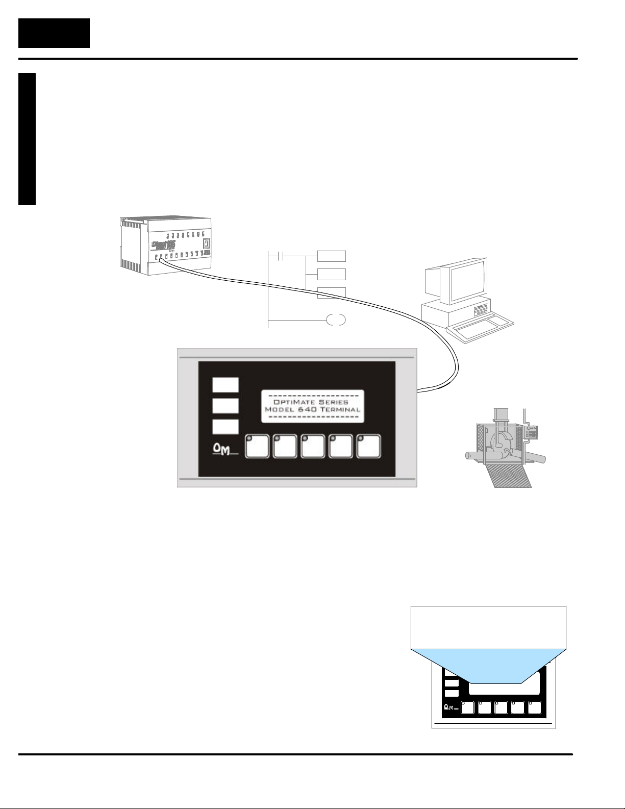
Let’s look at the OP--640 operator panel and its individually-supported features. As
you continue through this manual, try to relate the examples to your Operator Panel
application. The application worksheets located in Appendix A will be helpful during
the design and configuration of your system.
It is important to read and understand all topics discussed before installing,
configuring and programming your application. You should plan your system with all
operator interface requirements in mind.
OP-- WINEDIT
Pushbuttons...
Process Data.....
Memory Requirements...
MACHINE
General Panel
Information
LCD Display
Window
The OP--640 operator panel provides a man-machine interface to your PLC
automation system. This panel is not designed for applications which demand large
amounts of operator data entry. The panel communicates with your PLC using
RS-232 or RS-422 serial communication. Details on configuration software and
programming your operator panel are covered in later chapters. The OP--640
operator panel can be used in a stand alone fashion with one panel used with each
CPU RS-232 port, or can be used in multi-panel applications using an OP--9001
Commucations Master. You may network up to 31 panels using an OP--9001.
The OP--640 features an LCD display
window to display user-defined
messages. Up to 160 messages may be
configured and stored in the operator
panel using OP--WINEDIT configuration
software. The PLC logic program
controls which messages are displayed.
Details on how to enter and use
messages are covered in later chapters.
Backlit LCD Display with 4
lines, 20 characters each.
Page 12
G
e
t
t
i
n
g
S
t
a
r
t
e
d
1--
5
Getting Started
Pushbuttons
Annunciator
Lamps
Back-Panel Layout
Many applications require operator
panel pushbuttons for controlling the
machine or process. These pushbuttons
are used as input signals to the PLC
which start and stop a machine or
process. Configure these pushbuttons
as momentary or alternating to best fit
F1 F2 F3 F4
F5
your operator interface application. You
may create custom text labels.
The three lamps are turned
on, off and flashed through
your ladder logic program.
You may create custom text
labels.
Lamp 1
Lamp 2
Lamp 3
Pushbuttons
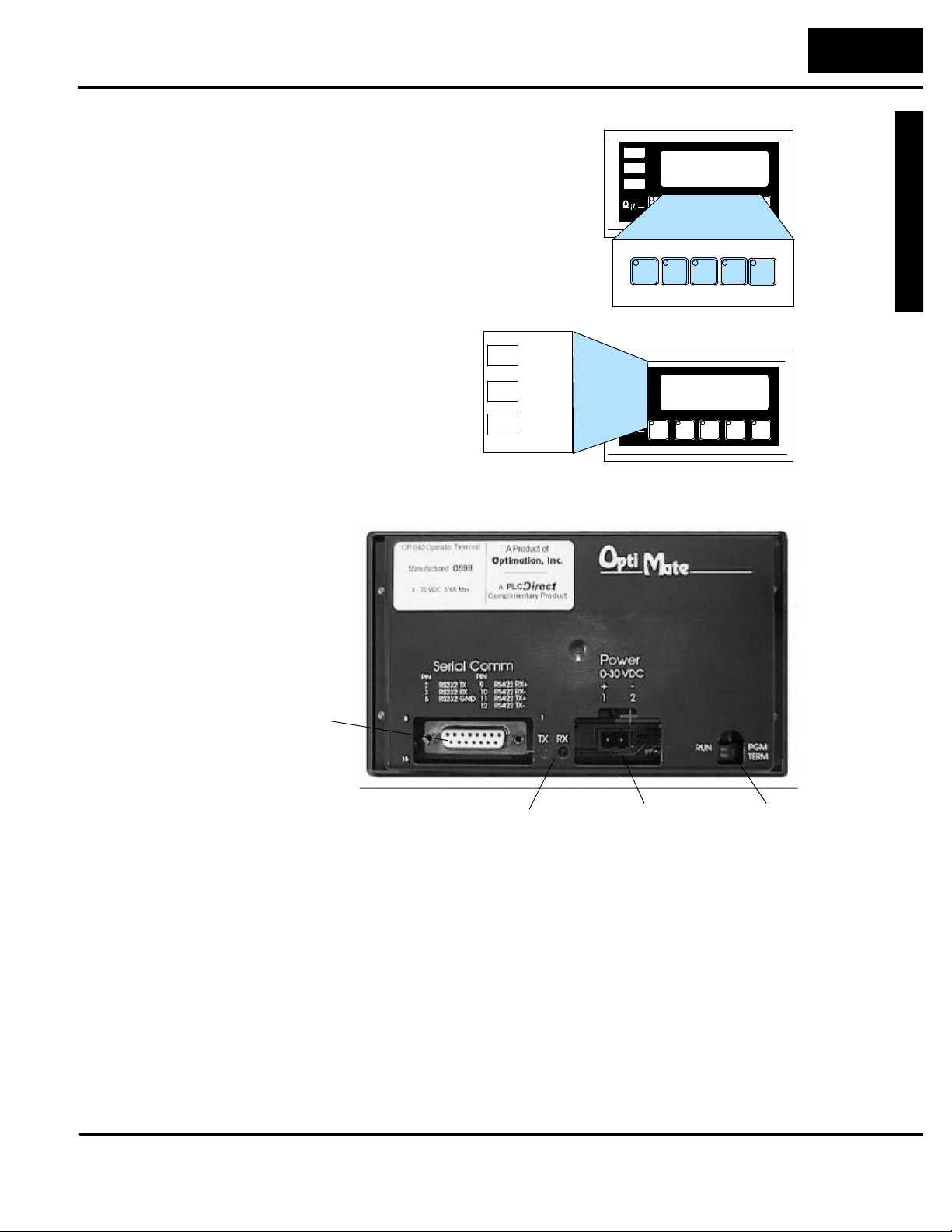
The back panel contains a serial communications port with transmit (TX) and receive
(RX) LEDs, a power receptacle, and RUN/PGM and TERM switches.
Serial
Communications
Port
Power Receptacle
RUN/PGM and
TERM Switches
Serial Port
TX LED
(Red)
RX LED
(Green)
Power Receptacle
RUN/PGM Switch
The serial communications port is a 15-pin, female D-shell connector, which
supports using RS-232 or RS-422 interface wiring. This port is used for
communications between the OP-panel and PLC, as well as for programming your
panel configurations. In the case of a Multi-panel application, this port may be
connected to the OptiMate OP-9001 Communications Master.
The supplied block style connector with screw terminals is used to connect an
external 24VDC power supply.
The RUN/PGM Switch must be set to ON (PGM) before downloading from the PC to
the panel. The TERM Switch is onlyset to ON(right position) when the panel is at the
end of a system using RS--422 communications. In all other cases, including
downloading, it is set to OFF (left position).
Page 13

GettingStarte
d
1--
6
Getting Started
Frequently Asked Questions
Q. What is required to get started using the OP--640 in my application?
A. You must read this manual and understand the OP-panel requirements and
application concepts. You must have programming knowledge for the PLC product
you’re using, the PLC serial communications capabilities which are available, as
well as hook-up and connecting cable data.
Q. How do I configure the OP--640 operator panel?
A. Using the OP-WINEDIT configuration software available from Automationdirect.
This software allows you to configure the OP-panels in a Microsoft Windowst
environment. You may configure your programs offline, upload, and/or download
them to your OptiMate panel. The OP-WINEDIT software is provided with
installation documentation and Help screens.
NOTE: OP--WINEDIT version 2.3 or later is required.
Q. Can the OP--640 be used with other PLC products?
A. Yes. The OP--640 does support Allen-Bradley SLC 5/03, SLC 5/04, and
Micrologix.
Q. What are the power supply requirements for the OP--640?
A. The OP--640 panel requires a 24VDC external power supply. See the
Specifications for details.
Q. Will the OP-panels support graphics, animation, or color operator display screens?
A. No. The OP-panels which support display capabilities allownumeric data display,
and some panels will also allow text message display.
Q. Can I connect more than one OP-panel to one PLC/CPU?
A. Yes, this is referred to as a Multi-Panel application. You may network up to 31
panels to communicate using RS-422 multi-drop communications between the
OP-panels and OP-9001 Communications Master unit. Also, if your CPU has
secondary ports, you may connect a single panel to each available serial port.
Q. Why does my panel lose communication after being in service for a period of time?
A. Once a panel gains communication with a PLC there areonly a fewreasons why it
does not continue: 1) RFI from nearby motors, welders, starters, etc. causing
anything from memory corruption to damaged driver chips; and 2) an inadequate
power supply.
Q. When I have my panel connected to a DL205, my LCD and/or lamps work, but my pushbuttons
don’t...why?
A. The Optimate module cannot WRITE to the PLC’s memory when the CPU’s
RUN/TERM switch is in the Run position, therefore only the LCD and/or lamps
visually function. The CPU should be set to the Term position in order for the
Optimate panel to write to it.
Page 14

G
e
t
t
i
n
g
S
t
a
r
t
e
d
1--
7
Getting Started
Q. My module will occasionally fail when I power up my system. Why does this happen?
A. Normally this is caused by an inadequate power supply corrupting the memory.
When determining the size of a power supply be sure to include ALL sources of
energy consumption and also account for the surge these devices require. For
example an OP--613 requires 1.5 Amps (for 2 milliseconds) at start-up, but after
start-up needs only 90 mA at 24VDC to function.
Q. My panel lights flash when connected to the bottom port of a D2--240. What’s wrong?
A. The lower port on the D2--240 defaults to ASCII mode and needs to be set toHEX
mode in order to communicate with anOptimate panel. Access the port settings from
DirectSOFT by PLC-->Setup-->Setup Secondary Com Port.
Q. In a multi--panel system, how should I wire the panels if more than one power supply is being
used?
A. It is highly recommended that all the power supply grounds be wired together.
Failure to do so may result in failed modules. Also, ensure that power supply and
wire size is large enough to handle the current, especially at long distances. It is also
highly recommended that all shields be tied to earth ground. For power cable
distances greater than 50’ or in noisy environments, a two-twisted pair shielded wire
such as Belden 9729 (or equivalent) should be used. There is an OP--9001
Supplemental Sheet with diagrams, included with all OP--9001’s, depicting the three
most typical wiring arrangements.
Q. Why does my module work in a stand-alone situation, but not when connected to my
OP--9001?
A. The most obvious reason is that the module was not configured for a multi-panel
situation or that the OP--9001 was not configured for the module. Next, the OP--9001
communicates with the module via RS--422 cable, so verify that the pin-outs are
correct. Lastly, the RS--422 driver in the module or OP--9001 may have failed due to
cabling or power supply problems. Please reference the OP--9001 Supplemental
Sheet for wiring directions.
Q. I’ve loaded a new configuration into my panel and still get some of the old messages. How do I
get rid of the old messages?
A. The OP--WINEDIT does not clear the message listin the OP panel when you load
a new configuration. If youhad more messages in the old configuration than the new
configuration, the extra messages do not get overwritten. You can clear the
message list from CONFIGURE>CLEAR LIST>THE CONNECTED PANEL. Reload
the new configuration and the old messages will be gone.
Page 15

2
Installation and
Specifications
In This Chapter. . . .
— Connecting a Power Supply
— Preparing Panel for Configuration
— Preparing Panel for Communications
— OP--9001 Multi--panel Configurations
— Choosing Connecting Cables
— Connecting Cable Details
— Labeling the Lamps and Pushbuttons
— Templates for Manually Creating labels
— Dimensions for Mounting
— Panel Specifications
Page 16
InstallationandSpecifications
2--
2
Installation and Specifications
Connecting a Power Supply
Power Supply
Connections
Multi-panel Power
Supply Connection
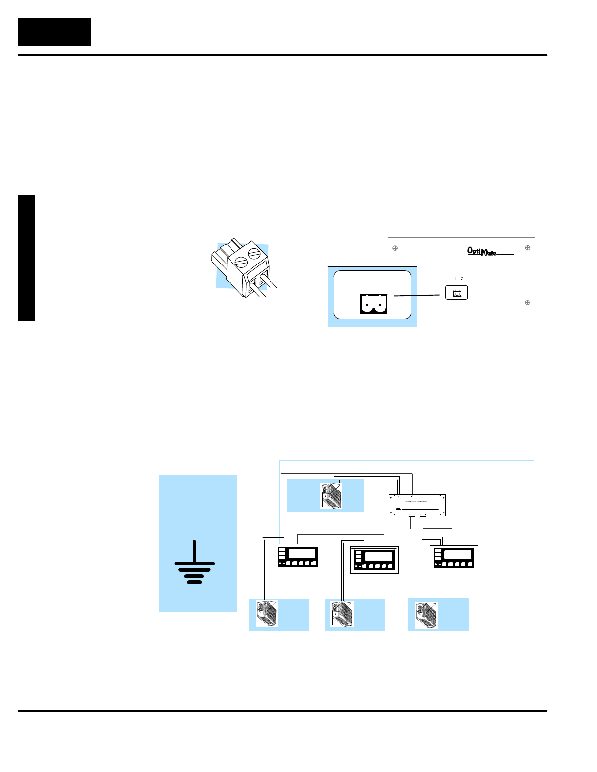
An external power supply is adapted tosupply operating voltage to the OP--640 unit.
The power supply must deliver a range between 8 to 30 VDC, and provide a
minimum of 5 watts continuous power to the units. Connect your power supply using
the terminal block connector supplied with each panel. The connector is keyed to
prevent reversing the polarity.
Use 18--24 AWG conductor wire and connect the
power supply to the connector block which is supplied with each operator panel. The terminal marked
1 is the positive (+8--30 VDC) connection and terminal 2 is the common ground (0V) connection.
--0V
Ground
+24VDC
Plug the terminal block connector into Power receptacle
located on the back side of the
panel.
+ -1 2
Receptacle
In Multi-panel applications, if separate power supplies are used, make sure the
electrical ground connections do not havea great potential difference. When using a
single power supply in a Multi-panel application, the powersupply must maintain the
specified voltage and current consumption levels under all conditions (including
power-up) for each of the individual units. See individual panel power requirements
under Panel Specifications.
+
8 to 30 VDC
0 VDC
Ground
(Communications to PLC)
Power
Supply
(RS-422)
Panel 1
Power
Supply
Power
Supply
Panel 2
OP--9001
J1
J2
etc...
Panel 3
Power
Supply
Page 17
I
n
s
t
a
l
l
a
t
i
onand
2--
3
Preparing the Panel for Configuration
Installation and Specifications
RUN/PGM
Switch
Configuration
Cable
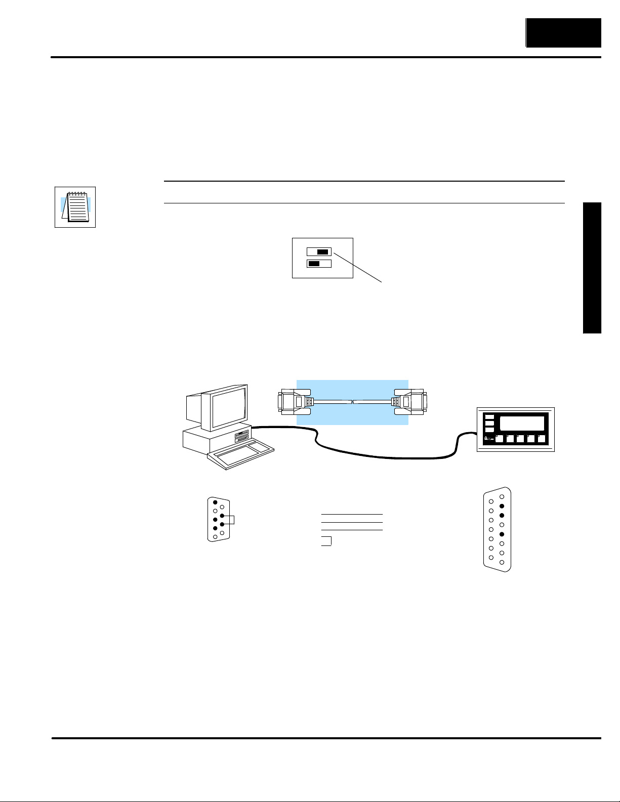
The RUN/PGM Switch must be set to PGM (ON) before downloading from the PC to
the panel. The TERM switch should remain off.
NOTE: You must cycle power to the panel to activate the new switch settings.
ON
RUN
1
2
PGM
TERM
Set to PGM
Connect the configuration cable (OP--ACBL--1) between the serial port of the
OP-panel and the serial port of the personal computer. The panel may then be
configured using the OP--WINEDIT configuration software. The figure below shows
programming cable connectors and wiring specifications. Wiring diagrams refer to
the cable connectors, not the communication ports.
OP--ACBL--1
Specifications
5= 0V
4= not used
3= Dout
2= Din
1= not used
Computer
9
9=not used
8= CTS
7= RTS
6=not used
1
Female Male
DB9 DB15
3 3
7
8
22
55
9= not used
10= not used
11= not used
12= not used
13= not used
14= not used
15= not used
Panel
1
1= not used
2= Dout
3= Din
4= not used
5= 0V
6= not used
7= not used
8= not used
Page 18
InstallationandSpecifications
2--
4
Installation and Specifications
Preparing the Panel for Communications
RUN/PGM
Switch
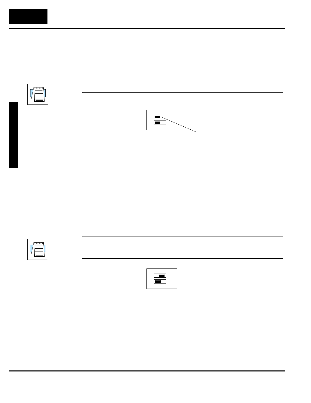
The RUN/PGM Switch must be set to RUN after loading the configuration program.
The TERM switch should remain off.
NOTE: You must cycle power to the panel to activate the new switch settings.
RUN
1
2
ON
OP--9001 Multi-Panel Configurations
If you are connecting more than one OptiMate panel to a single CPU this is referred
to as Multi-panel configuration. Multi-panel configurations require the OP--9001
Communications Master. The OP--9001 communicates with the CPU as well as the
connected OP--panels. The OP--9001 looks for an address within the range of 0 to
30 for each panel connected. Each panel connected in an RS-422 link must have a
unique address. A more detailed description of multiple panel configurations and
installation is given in the OP--9001--M User Manual.
The TERM Switch
When using an RS-422 communications link, the last panel must be terminated by
setting the TERM Switch to ON. Systems which are using the OP--9001 in a
multi-panel application use RS-422 wiring. Operator panels communicating more
than 50 feet distance must use RS-422 links. The TERM Switch stays OFF for
RS--232 communications.
PGM
TERM
Set to RUN
NOTE: Only the last panel of each RS-422 link should be terminated (TERM switch ON). All
other panels must have the TERM switch OFF. After changing the DIP switch settings,
remember to cycle power on the panel to activate the new switch settings.
ON
RUN
1
2
PGM
TERM
Page 19
I
n
s
t
a
l
l
a
t
i
onand
2--
5
Installation and Specifications
CPU
FamilyCPU
PortCable
DL205
DL305
DL405
DL440
*
*
SIMATICâTI305
SIMATICâTI405
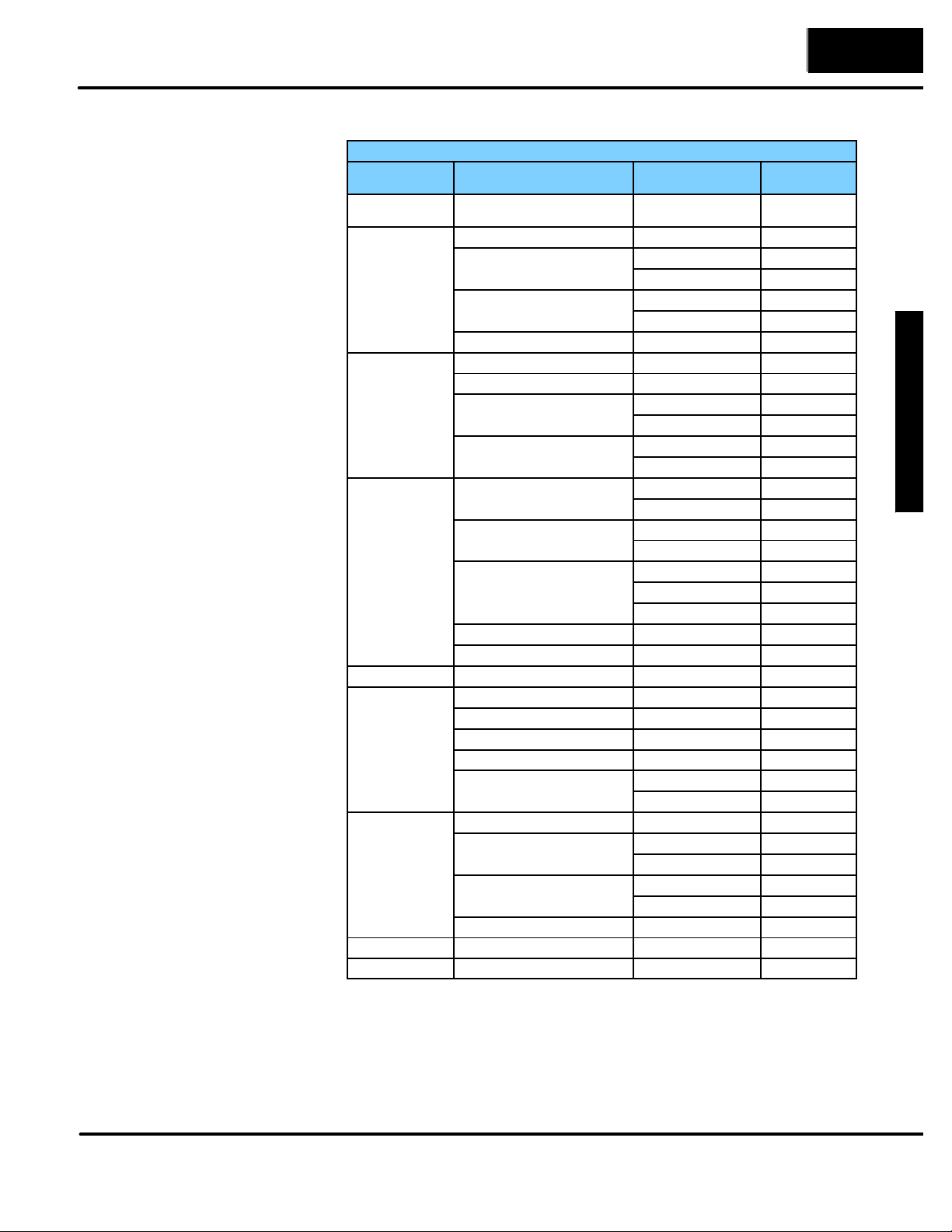
Choosing
Connecting Cables
Depending on which PLC you are
using, you may require as many as
two cables. Here are the
requirements:
D OP-ACBL-1: all units require
this cable for configuration. This
is a 9-pin female to 15-pin male
cable that connects your
personal computer to the
OP-panel. This cable is also
used to connect an OP-panel to
the Allen-Bradley SLC 500
CPUs.
D CPU Cables: You will also need
the appropriate cable to connect
your CPU to the OP-panel. Use
the chart shown to the right to
choose the correct
communications cable.
OP-9001 Cable Connectors
If you’re planning to use multiple
panels and an OP-9001, then you’ll
need to build your own custom
cables. Since the proper cable
choice really depends on your
application, we offer the following
connectors.
D OP-CMCON--1 — pack of 4
ribbon cable connectors.
D OP-CMCON--2 — pack of 4
solder-type connectors.
D OP-CMCON--3 — pack of 2
D--shell connectors with screw
terminals for use with OP-9001
& multiple OP-panels.
D OP-PSCON — pack of 4 power
supply block connectors.
For electrically noisy environments,
we recommend an individually paired
and shielded cable, such as Belden
9729 or equivalent. This type of cable
will require the solder-type or D-shell
with screw terminal connectors. If
you’re going 30 feet or less, you can
use ribbon cable. For ribbon cable,
we recommend Belden 9L28015 or
3M 3365/15.
OptiMate Cables
Family
DirectLOGICt
DL05 / DL105
DirectLOGICt
DirectLOGICt
DirectLOGICt
GEâSeries 1 IC610CPU105/106 Requires DCU* OP-4CBL--2
TI305t /
TI405t /
A--B SLC 500 5/03, 5/04 Bottom port OP-ACBL -- 1
A-B MicroLogix Only port OP-ACBL--2
t
t
(or other device)
DL05: D0--05
DL105: DL130
DL230 Only port OP--2CBL
DL240 Top port OP--2CBL
DL250 Top port OP--2CBL
D2--DCM (module) Only port OP-4CBL--2
DL330 Requires DCU* OP--4CBL--2
DL330P Requires DCU* OP-4CBL--2
DL340 Top port OP-3CBL
DL350 Top port OP-2CBL
DL430 Top port (15-pin) OP-4CBL--1
DL440**
DL450** Phone Jack OP-2CBL
D4--DCM (module) Only port OP-4CBL--2
Slice I/O panels Only port OP-4CBL--1
325--07, PPX:325--07 Requires DCU* OP-4CBL--2
330--37, PPX:330--37 Requires DCU* OP-4CBL--2
325S--07 (or 325 w/ Stage Kt) Requires DCU* OP-4CBL--2
330S--37, PPX:330S--37 Requires DCU* OP-4CBL--2
335--37, PPX:335--37 Phone Jacks OP-3CBL
425--CPU, PPX:425--CPU ** Only port OP-4CBL--1
PPX:430--CPU Top port (15-pin) OP-4CBL--1
435--CPU, PPX:435--CPU ** Top port (15-pin) OP-4CBL--1
Smart Slicet I/O panels Only port OP-4CBL--1
DL05: Both ports
DL105: Only one port
Bottom port OP -- 2CBL
Bottom port OP -- 2CBL--1
Bottom port OP-3CBL
Bottom port OP-4CBL-2
Bottom port (25-pin) OP-4CBL--2
Top port OP-4CBL--1
Bottom port OP-4CBL -- 2
Top port (15-pin) OP-4CBL--1
Bottom port (25-pin) OP-4CBL--2
If DCU is used* OP-4CBL--2
Bottom port (25-pin) OP-4CBL--2
Bottom port (25-pin) OP-4CBL--2
OP--2CBL
Specifications
* — requires RS232 Data Communications Unit (D3--232--DCU)
**-- also available in DC versions
Page 20
InstallationandSpecifications
2--
6
Installation and Specifications
Connecting Cable Details
Connecting Cable
RJ12 (PLC) DB15
4 3
15-pin (PLC)
2 3
4
5
RJ11 (PLC)
2 3
DB15 (PLC)
2 3
13
14
15
1
7
8
DB25 (PLC)
2 3
4
5
8 Pin Mini DIN
7 3
23
51
DB15
23
57
DB15
21
54
DB15
23
54
DB15
23
57
DB15
24
52
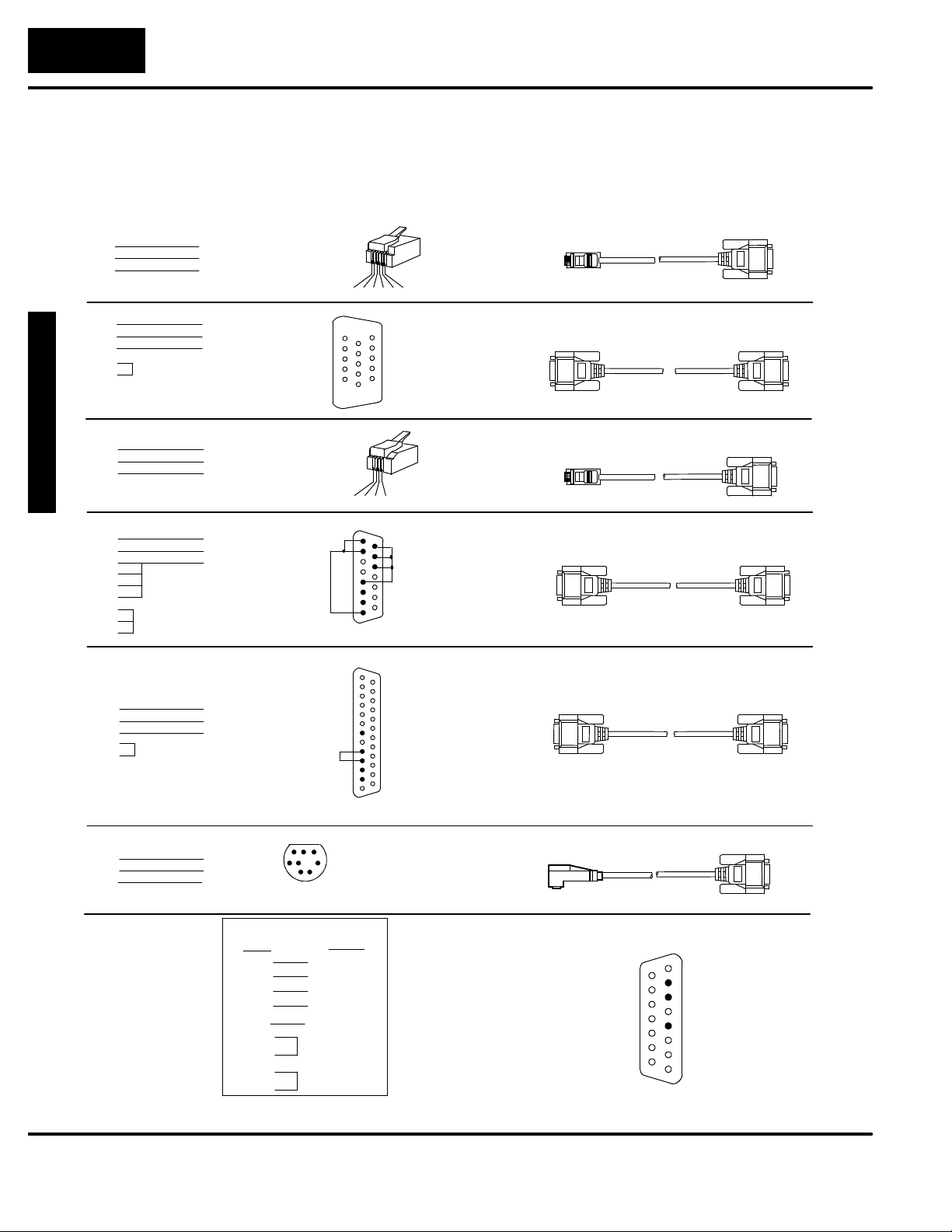
The OP--640 connecting cable may vary depending on the CPU used. Refer to the
previous page to confirm the proper cable is chosen for connecting to your PLC.
1= 0V
PLC
2= not used
3= Din
4= Dout
5= not used
6= not used
8= not used
7= 0V
6= not used
5= CTS
4= RTS
3= RXD
2= TXD
1= not used
1= Din
2= Dout
3= not used
4= 0V
8= YOM
7= CTS
6= not used
5= not used
4= On-line
3= Din
2= Dout
1= YOP
13= not used
12= not used
11= not used
10= not used
9= not used
8= not used
7= 0V
6= not used
5= CTS
4= RTS
3= Din
2= Dout
1= not used
716 8
4
3
RJ12
3 4 5 621
15= not used
14= not used
13= not used
12= not used
11= not used
10= not used
9= not used
RJ11
1 23 4
15
15= tied (0V)
14= tied (0V)
13= tied (0V)
12= not used
11= not used
10= not used
1
1
5
2
9= not used
25= not used
25
24= not used
23= not used
22= not used
21= not used
20= not used
19= not used
18= not used
17= not used
16= not used
15= not used
14= not used
3= Din
2= Dout
=0V
5
RJ12
(6P6C)
15-pin
RJ11
(4P4C)
DB15
Mini--DIN
OP--2CBL
OP--2CBL--1
OP--3CBL
OP--4CBL--1
OP--4CBL--2
OP--ACBL--2
DB15
DB15
DB15
DB15
DB15DB25
DB15
RS-422 Pinout
PLC
Din +
Din -Dout +
Dout --
0V =0V
RTS+
CTS+
RTS-CTS--
Panel
11
= Dout+
= Dout --
12
9
= Din +
= Din--
10
5
9= not used
10= not used
11= not used
12= not used
13= not used
14= not used
15= not used
Panel
1
1= not used
2= Dout
3= Din
4= not used
5= 0V
6= not used
7= not used
8= not used
15
Page 21
I
n
s
t
a
l
l
a
t
i
onand
2--
7
Labeling the Lamps and Pushbuttons
Installation and Specifications
Labeling the
Lamps and
Pushbuttons
Creating the
Labels
In any manufacturing environment it is
important to have legible labels on the
pushbuttons. Labeling the OP--640
panel is a relatively simple process that
involves removing the bezel and sliding
a label transparency into a pocket in the
panel overlay. The transparent film can
be purchased from almost any office
supply store in standard 8-1/2” x 11”
sheets. It is designed to run through a
copy machine or laser printer.
The easiest way to create labels is to use the built-in label making function of the
OP--WINEDIT configuration software. This is the preferred method and is shown
below.The labels can also be createdmanually using the templateshown in thenext
section to help layout the transparency film. Here are some ways of manually
creating labels:
S Use a computer graphics program and a laser printer to create the
transparency directly, or print the labels on paper and photocopy them
to a transparency sheet.
S Use press-on letters on a transparency sheet.
S Use a typewriter or lettering machine, or use press-on letters to create
labels on a paper sheet, then photocopy the paper sheet onto a
transparency sheet.
Specifications
Creating
Labels Using
OP--WINEDIT
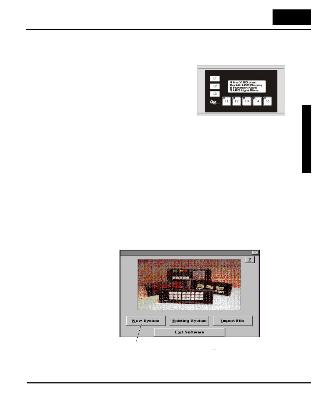
Making labels using the OP--WINEDIT configuration software is easy (see Chapter 4
for information on loading and using OP--WINEDIT). After loading OP--WINEDIT,
follow these steps:
Open OP--WINEDIT and select New System.
1.
Page 22
InstallationandSpecifications
2--
8
Installation and Specifications
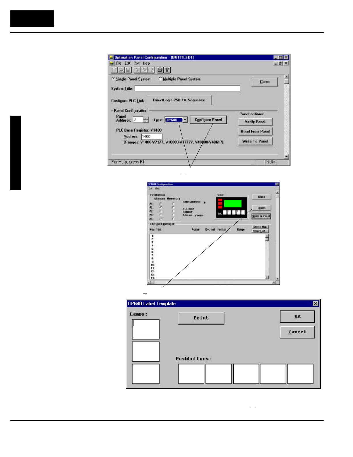
Select OP--640, and Configure Panel.
2.
Select Labels.3.
The OP--640 Label Template appears. Type in the label text for the
4.
five pushbuttons and the three lamps. Press OK to save the labels.
Page 23
I
n
s
t
a
l
l
a
t
i
onand
2--
9
Installation and Specifications
Printer
5. Print label on transparent film.
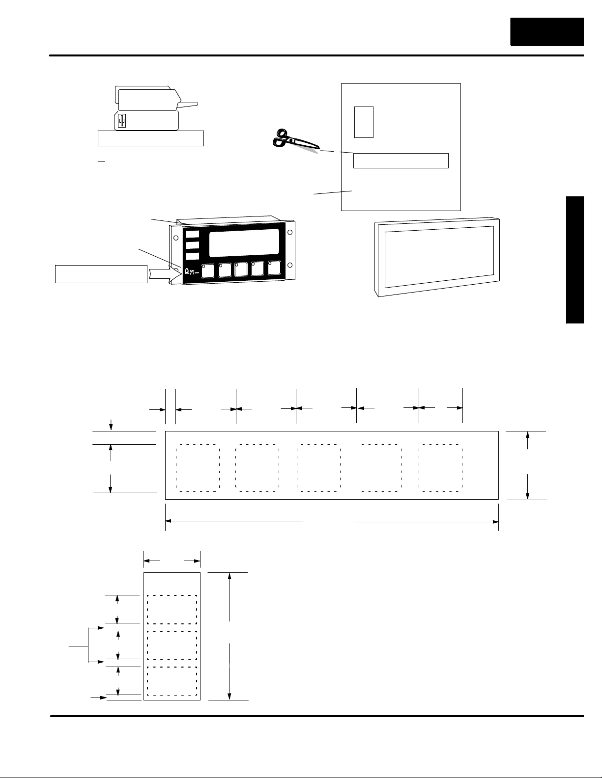
6. Cut out the block of labels and
insert them in the panel.
Pocket for Lamps
Pocket for
Pushbutton
Start Set
Next
Prev.
Stop
Transparent
Sheet
OP640 LABEL TEMPLATES
Lamp Template:
L1
L2
L3
Pushbutton Template:
Start Setup
Bezel
Next Prev.
Stop
Remove the bezel from the module by unsnapping the four plastic tabs which secure the bezel to the
module frame. Locate the pocket, and carefully slide the labels into place. Re-attach the bezel by
snapping the bezel onto the case.
Templates for Manually Creating Labels
Specifications
0.09”
0.025”
0.11”
0.65”
0.50”
0.50”
0.50”
0.08”
0.85”
0.80”
0.80”
0.80”
0.80”
4.45”
Pushbutton Label Strip Pattern
2.21”
Indicator Lamp Label Strip Pattern
0.65”
0.81”
Page 24
InstallationandSpecifications
2--10
Installation and Specifications
Dimensions for Mounting
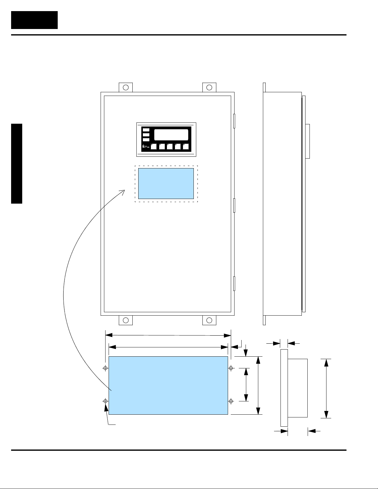
Cutout Area
Example panel mounting
6.20”
5.80”
0.20”
0.75”
0.50”
2.00”
3.56”
3.55”
0.16” DIA,
four places
Dimensions in Inches
1.15”
Page 25

I
n
s
t
a
l
l
a
t
i
onand
2--11
Panel Specifications
Physical
Specifications
Environmental
Specifications
Weight 12 ounces. . . . . . . . . . . . . . . . . . . . . . . . . . . . . . . . . .
Panel Fasteners Four 6x32 threaded studs. . . . . . . . . . . . . . . . . . . . . . . . . .
Pushbutton Life 1,000,000 switch cycles. . . . . . . . . . . . . . . . . . . . . . . . . . .
LCD Display 4 line x 20 character STN with. . . . . . . . . . . . . . . . . . . . . . . . . . . . . .
Lamp Colors Red, Yellow and Green. . . . . . . . . . . . . . . . . . . . . . . . . . . . . .
NEMA Rating NEMA 4 (when properly installed). . . . . . . . . . . . . . . . . . . . . . . . . . . . .
Operating Temperature 0° to 50° C. . . . . . . . . . . . . . . . . . . . .
Storage Temperature --20° to 70° C. . . . . . . . . . . . . . . . . . . . . .
Operating Humidity 95% (non-condensing). . . . . . . . . . . . . . . . . . . . . . . .
Air Composition No corrosive gases permitted. . . . . . . . . . . . . . . . . . . . . . . . . . .
Installation and Specifications
LED backlight; 4.75mm high x 2.95mm
wide character size
Specifications
Operating
Specifications
Power Consumption 2.4W @ 8--30VDC. . . . . . . . . . . . . . . . . . . . . . .
(Power On surge of 1.5--2.0A for
1 ms max.)
Power Connector Keyed terminal block. . . . . . . . . . . . . . . . . . . . . . . . . .
Diagnostics LED Status. . . . . . . . . . . . . . . . . . . . . . . . . . . . . . .
Communication Link RS-232. . . . . . . . . . . . . . . . . . . . . . .
4800 to19200 baud
15 pin female D shell connector
Message Types (160 max.) General Text. . . . . . . . . . . . . . . . .
Data display (one value per line)
Numeric Types & Values Integer. . . . . . . . . . . . . . . . . . .
Fixed Point
BCD (values 0 -- 9999, with appropriate
decimal placement)
BCD Double (values 0 -- 99999999, with
appropriate decimal placement)
Binary (values 0 -- 65535, with
appropriate decimal placement)
Floating Point (values --3.402823E+38
to 3.402823E+38 with appropriate
decimal placement)
Page 26

3
Understanding the
Features
In This Chapter. . . .
— Learning the Features
— Status and Control Registers
— Messages
— Displaying Messages
— Pushbuttons and Lamps
— Memory Mapping Process
— DirectLOGIC User Memory Overview
— Mapping Operation
— Mapping Example (DL05/105/DL205/D3--350/DL405)
— Mapping Example (D3--330/340)
Page 27
UnderstandingtheFeaturestheFeatures
3--
2
Installation and Specifications
Learning the Features
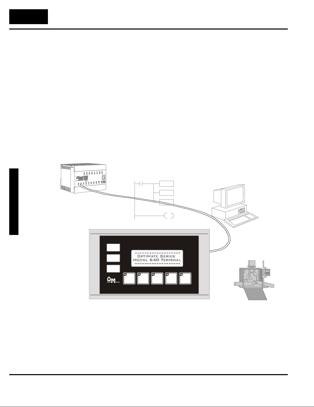
In this section, the subject of how to use the OP--640 features is described. The
details for using pushbuttons and messages are covered. We recommend that you
study this chapter before attempting to configure and use the OP-panel. As you
proceed through this chapter, relate the topics discussed with how your operator
panel may be implemented. The concepts discussed inthis chapter are applicable to
all PLCs.
SMessage and Menu Operations
SMemory Mapping Process
SControlling the Lamps
SUsing the Pushbuttons
SStatic Messages
SDynamic Messages
PLC
Process Data.....
OP-- WINEDIT
Pushbuttons...
Memory Requirements...
MACHINE
Page 28
U
nde
r
s
t
andin
g
U
nde
r
s
t
andin
g
3--
3
Status and Control Registers
Installation and Specifications
Status and Control
Register Overview
Bit Level Access
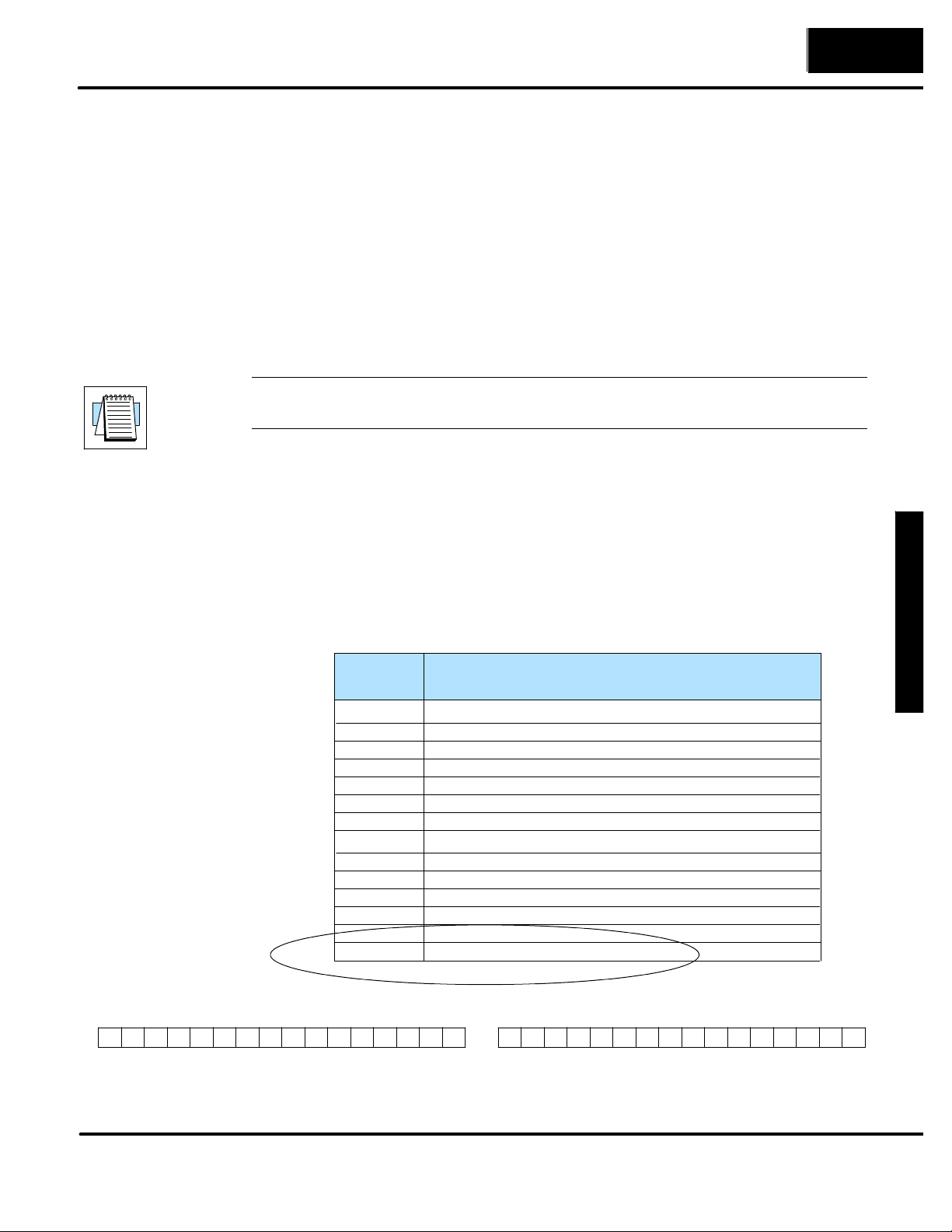
The OP-panels communicate to the PLC through user defined PLC data registers.
The starting or “Base” register is assigned during panel configuration and
automatically occupies fourteen consecutive 16--bit data registers. In this manual
the registers are identified as M+0, M+1, M+2, thru M+13. Each OptiMate panel
which is connected to the PLC maintains separate Status and Control registers
within the PLC. These registers (M+12, M+13) contain information to monitor and
control individual OP-panel functions and features. Shown in the figure below, base
registers M+12 and M+13 must have bit level access by the user control program.
That means Status and Control word register memory (OP-panel Base registers)
must be mapped to user memory bit registers. These bit registers are referred to as
Internal Control Relays such as C0, C1, etc.
NOTE: Depending on which CPU is used and the Base memory which is assigned, the
Status and Control registers may not require the mapping process.
Once again, the Status and Control bits are monitored and manipulated by the PLC
ladder logic. For discrete operations such as pushbuttons and lamps, the registers
M+12 and M+13 bits are accessed by the PLC control program. The figure below
shows the fixed definition of the Status and Control register bits. These bits are
labeled F1--F5 (Pushbuttons), L1--L3 (Lamps), for example. The bits and associated
labels are described on the following page. First examine the figure below to begin
understanding the OP-panel registers and functions. You must structure your ladder
logic program to coordinate OP-panel functions asynchronously. This means the
operations are triggered successively--not by a clock, but by the completion of an
operation.
the Features
the Features
MSB
PLC Register
Register
M+0
M+1
M+2
M+3
M+4
M+5
M+6
M+7
M+8
M+9
M+10
M+11
M+12
M+13
Status Register M+12
12131415 891011 4567 0123
F5 F1F2F3F4
Function
Top line message selection
Second line message selection
Third line message selection
Bottom line message selection
Top line data
Top line data 2 (for long BCD and floating point numbers)
Second line data
Second line data 2 (for long BCD and floating point numbers)
Third line data
Third line data 2 (for long BCD and floating point numbers)
Bottom line data
Bottom line data 2 (for long BCD and floating point numbers)
Status register
Control register
LSB
MSB
12131415 891011 4567 0123
Control Register M+13
LF2LF3BD L1L2L3LF1
LSB
Page 29

UnderstandingtheFeaturestheFeatures
3--
4
Installation and Specifications
MSB
MSB
Register Definition
The following describes the function of each of the registers shown in the table.
S Register M+0 -- When a number from 1 to 160 is placed in this register,
the predefined message associated with that number will
be displayed on the top line of the LCD display.
S Register M+1 -- When a number from 1 to 160 is placed in this register,
the predefined message associated with that number
will be displayed on the second line of the LCD display.
S Register M+2 -- When a number from 1 to 160 is placed in this register,
the predefined message associated with that number will
be displayed on the third line of the LCD display.
S Register M+3 -- When a number from 1 to 160 is placed in this register,
the predefined message associated with that number
will be displayed on the bottom line of the LCD display.
S Register M+4 -- This contains numeric data associated with the top line
display (this is described in more detail later).
S Register M+5 -- This is used for long BCD and floating point data only.
S Register M+6 -- This contains numeric data associated with the second
line display (this is described in more detail later).
S Register M+7 -- This is used for long BCD and floating point data only.
S Register M+8 -- This contains numeric data associated with the third
line display (this is described in more detail later).
Status and Control
Register Definition
12131415 891011 4567 0123
S Register M+9 -- This is used for long BCD and floating point data only.
S Register M+10 -- This contains numeric data associated with the bottom
line display (this is described in more detail later).
S Register M+11 -- This is used for long BCD and floating point data only.
S Register M+12 -- This is the Status Register (details below).
S Register M+13 -- This is the Control Register (details below).
The Status register (M+12) and Control register (M+13) are used for data exchange
between the OP-panel and PLC program. The figure below showsthe individual bits
within each data register. The function of the Status and Control register bits are
described below. Mapping these registers is covered at the end of this chapter.
Status Register M+12
F5 F1F2F3F4
LSB
12131415 891011 4567 0123
Control Register M13
LF2LF3BD L1L2L3LF1
LSB
Status Register (M+12):
F1--F5 -- Are the status function for the OP-panel definable pushbuttons. These bits
are set to 1 (ON) when the button is active.
Control Register (M+13):
L1--L3 -- Lamp ON/OFF control for each of the three lamp annunciators. Set to 1
(ON) to turn the lamp on.
LF1--LF3 -- Lamp Flash control for each of the three lamp annunciators. To flash the
lamp set Lamp and Lamp Flash bits both to 1 (ON).
BD-- Buzzer Disable. If set to 1 buzzer does not beep when buttons are pressed.
Page 30

U
nde
r
s
t
andin
g
3--
5
Messages
Installation and Specifications
Displaying
Messages on the
LCD Screen
Static Messages
Through the OP--WINEDIT software, up to 160 predefined messages can be
entered and stored in the OP--640. These messages are 20characters long andcan
include a field for the display of numeric data.
Any predefined message can be displayed on either the top or bottom line. The
messages entered during configuration are numbered 1 thru 160. To display a
particular predefined message on the display, simply place that message’s number
in the message selection register.
For example, let’s assume that we have
defined message #16 as “Mary had a
little” and message #22 as “white fleeced
lamb”. If we wanted to put these twolines
on the top and second lines respectively,
we would simply need to put the number
16 in register M+0 and 22 in registerM+1.
If any number other than 1 thru 160 is
placed in a message selection register,
the associated line will not change.
There are two types of messages which may be displayed on this panel, Static and
Dynamic messages.
Static messages are text displays which
have no embedded data. The static
messages may be displayed when an
event or condition becomes true. You
enter the messages during
configuration.
To display message #16 here,
place 16 in register M+0.
Example Message:
Mary had a little
white fleeced lamb
To display message #22 here,
place 22 in register M+1.
Example Static Message:
SYSTEM RUNNING
the Features
Dynamic Messages
Dynamic messages are text messages
which include embedded data. These
messages are used to present the
operator with important PLC data. This
data is information which helps the
operator closely monitor and control the
machine or process.
Example Dynamic Message:
Zone1 Temp.: ^^^^
Data Value update from PLC registerData Value update from PLC register
Page 31
UnderstandingtheFeaturestheFeatures
3--
6
Installation and Specifications
Displaying Messages
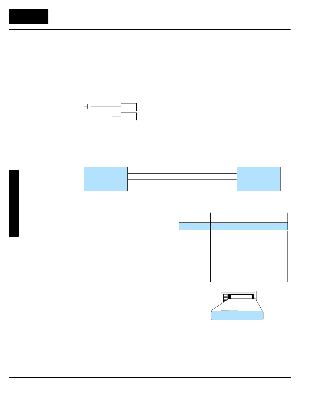
The logic required to display the configured message is quite simple. Simply put the
message number (1--160) in memory location M+0 for the top line message, M+1 for
the second line message, M+2 for the third line message, or M+3 for the bottom line
message. The figure below demonstrates an example of a Static message with the
panel configured for a starting address of V2000.
Static Message
Operation
Static Display
X3
ON
LD
K3
OUT
V2000
Selects message#
for Top line
M+0
OP-Panel
Register
M+0
Message # request
Description
All supported CPUs use the first
OP-panel register for displaying a
top line static message.
Your ladder logic program must
sequence the message being
displayed by placing an integer
value (1--160) in register M+0.
The OP-panel operating system
automatically updates the latest
messages according to values
placed in the highlighted registers.
In this example, if the PLC’s input signal X3 is
ON, the 16 bit integer (K3) value is placed in
Word register V2000 (M+0), selecting message
#3 to be displayed on the top line.
Example PLC
User Memory
V2000 = 3
Top Line Static Message
Register
Value
M+0
M+1
M+2
M+3
M+4
M+5
M+6
3
Function
Top line message selection
Second line message selection
Third line message selection
Bottom line message selection
Top line data
Top line data 2
Second line data
Example Message #3
System Running
Page 32
U
nde
r
s
t
andin
g
3--
7
Installation and Specifications
Dynamic Message
Operation
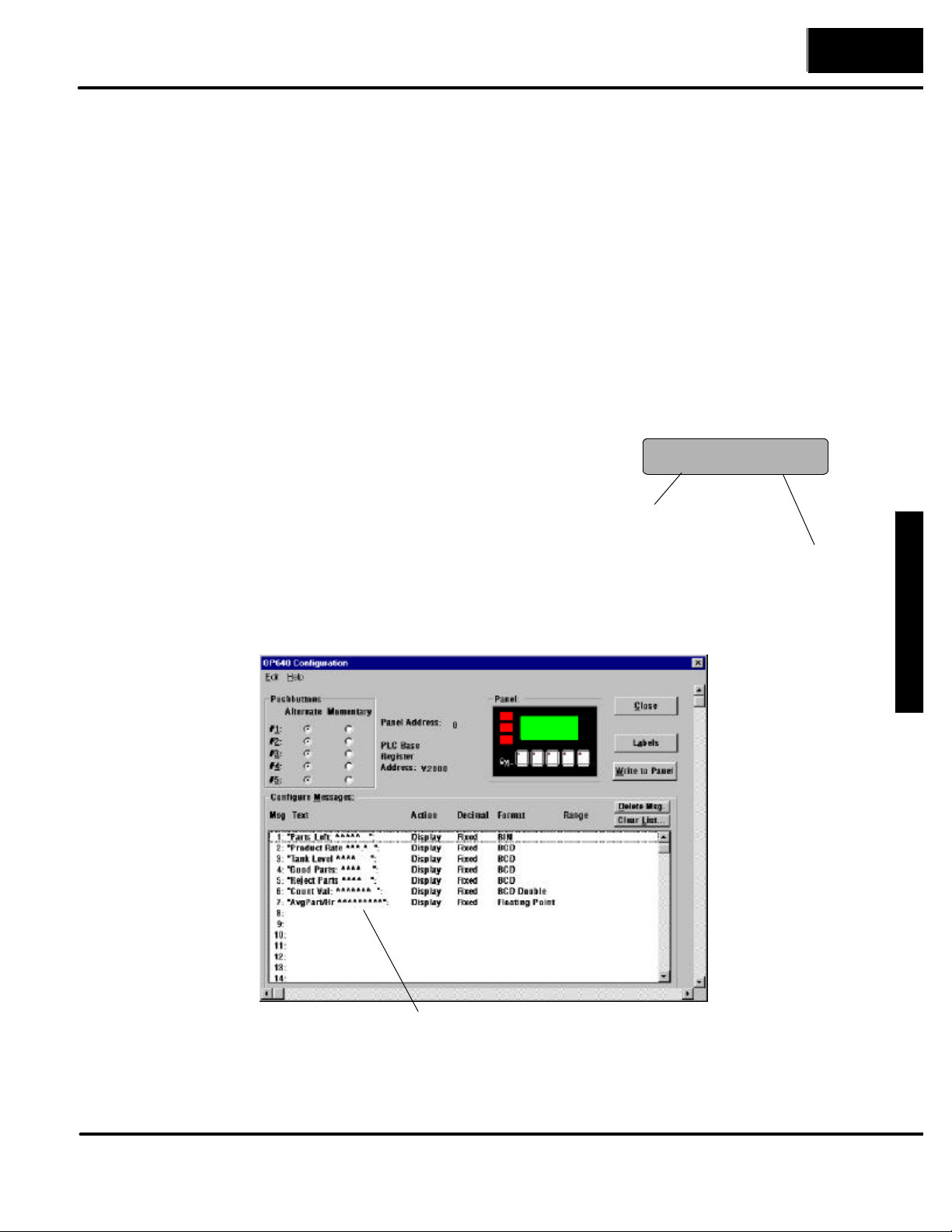
You may program message numbers 1--160 to be used as dynamic messages. One
numeric field per line is allowed. Dynamic messages may be displayed on either the
top or bottom display lines. The maximum number of digits which may be displayed
is five if binary data format is used, four if BCD is used, and eight if BCD double is
used. The figure below demonstrates the OP--WINEDIT screens for programming a
dynamic message.
Enter the message text and place the caret (^) symbol(s) depending on the number
of digits you would like to display. The value range which may be displayed is
0--65,535 integer, 0--9999 BCD or 0--99999999 BCDD. Choose binary,BCD, or BCD
double format and fixed point decimal placement.
For dynamic messages which require fixed decimal point placement within the
value, you must use the OP--WINEDIT to perform parameter placement type. For
fixed position decimal points you must enter the decimal directly into the message
text, such as Zone1 Temp = ^^.^^.
For example, let’s say message #36 is “#
widgets sold: ^^^^”. Let’s also say that
465 widgets have been sold today. To
display the current number of widgets
sold on the bottom line of the display, you
would place 36 in register M+3 and 465 in
register M+10. The bottom line would
then display: “# widgets sold: 465”.
Place 36 in register M+3;
message is “# widgets sold: ^^^^”.
Example Message #36:
# widgets sold: 465
To display this, 465 must
be in register M+10.
the Features
Examples of dynamic messages. Notice
the caret (^) symbols, which is where data
will be when the message is displayed.
Page 33
UnderstandingtheFeaturestheFeatures
3--
8
Installation and Specifications
Dynamic Message
Top Line
X4
ON
LD
K10
OUT
V2000
LD
V3000
OUT
V2004
Selects message#
for Top line
M+0
Loads variable data
M+4
OP-Panel
Register
M+0
Message # requested
M+4 Top line message data
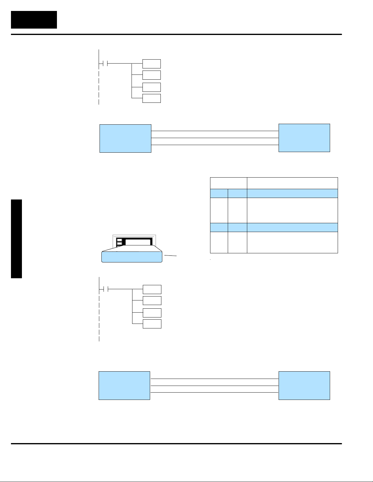
Remember, your ladder logic
program must select the message
being displayed by placing an
integer value between 1 and 160
(message #) in register M+0. The
embedded data for the top line
message is controlled by loading a
16 bit value into register M+4.
Example Message #5
In this example, if the PLC’s input signal X4 is
ON, the 16 bit integer (K10) value is placed in
Word register V2000 (M+0) selecting message
#10 to be displayed on the top line. The data value in register V3000 (let’s say 1100) is moved
into V2004 (M+4), which is embedded in the top
line message. The top line data value will update
as long as X4 is enabled (ON).
Example PLC
User Memory
V2000 = 10
V2004 = 1100
Top Line Dynamic Message
Register
Value
M+0
10
M+1
M+2
M+3
M+4
1100
M+5
M+6
Function
Top line message selection
Second line message selection
Third line message selection
Bottom line message selection
Top line data
Top line data 2
Second line data
Dynamic Message
Bottom Line
Zone1 Temp. = 1100
X5
ON
LD
K12
OUT
V2003
LD
V3001
OUT
V2012
OP-Panel
Register
M+3
M+10
The highlighted registers M+0 and M+4 in this figure
result in displaying this top-line dynamic message.
Selects message #
for Bottom line
M+3
Loads variable data
M+10
Message # requested
Bottom line data message
In this example, if the PLC’s X5 input signal is
ON, the 16 bit integer (K12) value is placed in
Word register V2003 (M+3) requestingmessage
#12 to be displayed on the bottom line. The data
value in register V3001 (let’s say 1101) ismoved
into V2012 (M+10), which is embedded in the
bottom line message. The bottom linedata value
will update as long as X5 is enabled (ON).
Example PLC
User Memory
V2003 = 12
V2012 = 1101
Page 34
U
nde
r
s
t
andin
g
3--
9
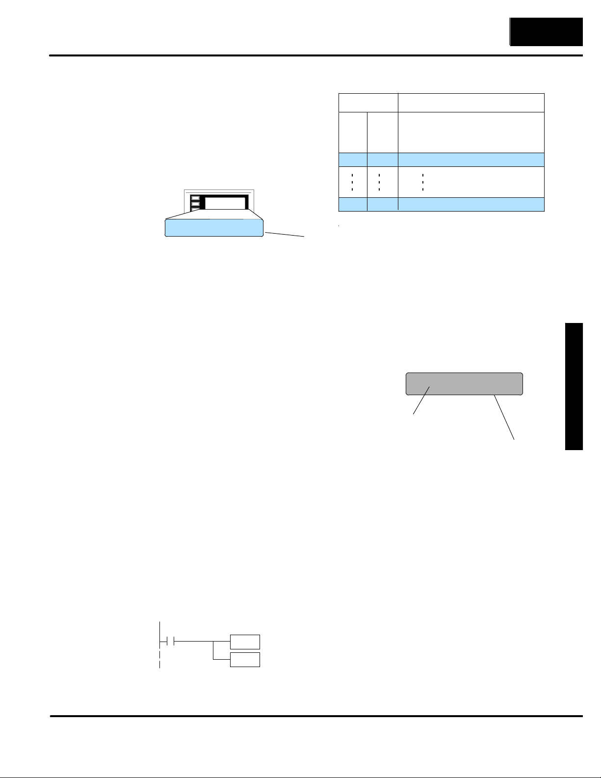
Remember, your ladder logic
DisplayingBCD
DoubleNumbers
program must select the bottom line
message being displayed by placing
an integer value between 1 and 160
(message #) in register M+3.
Example Message #12
Installation and Specifications
Bottom Line Dynamic Message
Register
Value
M+0
M+1
M+2
M+3
12
Function
Top line message selection
Second line message selection
Third line message selection
Bottom line message selection
Displaying Data
With a Decimal
Point
Bottom line data
Zone2 Temp. =1101
M+10
The highlighted registers shown in this figure results in
displaying this bottom-line dynamic message.
1100
The OP--640 panel allows you to display fixed point numbers, which are numeric
values that have a known decimal point placement and are simply handled as
integer values within the PLC program. The only time you see an actual decimal
point is on the LCD display. An example of a fixed point number is a program that
uses temperature as a control variable, and within the program all temperatures are
scaled in tenths of a degree. The values are integer, so a temperature of 73.5
degrees would be 735 in a data register. For the convenience of the operator, you
would want the LCD display to include the decimal.
Fixed point numbers are handled by
simply placing a decimal point or period
Example Message #47:
Temperature: 73.5
in the message field during
configuration.
For example, let’s say you want to
display the message “Temperature:
Place 47 in register M+0;
message is “Temperature: ^^^.^”
73.5” on the top line, and the message is
#47. Enter message #47 as
“Temperature:^^^.^” during
To display this, 735 must
be in register M+4.
configuration.
the Features
Displaying BCD
and Binary
Numbers
Normally, numeric values to be displayed are valuescontained in one 16-bitregister.
One 16-bit register will handle values between 0 and 65535 in binary form, or
between 0 and 9999 in BCD form. For these type numbers register M+4 is used for
the numeric value for the top line, M+6 is used for the second line, M+8 is used for the
third line, and M+10 is used for the bottom line.
The OP--640 will handle large numeric numbers. If you select the option BCD
Double when the display message is being defined, your display can handle
numbers between 0 and 99,999,999. The panel will use data in the register pair M+4
and M+5 for the top line, and use M+6 and M+7 for the second line, etc. The data
must be in BCD.
LDD
OUTD
Notice that double registers are used.
V
V
M+2 & M+3
Page 35

UnderstandingtheFeaturestheFeatures
3--10
Installation and Specifications
Displaying Floating
Point Numbers
When placing a BCD double number in the
display registers, the first register numerically
Example: BCD Double
92345678
in the sequence of two registers (M+4, M+6,
M+8 or M+10) will contain the four least
significant digits of the number. The second
register in the sequence (M+5, M+7, M+9 or
M+11) contains the data for the four most
significant digits of the BCD double number.
9234 must be in
register M+5
For example, to display the number
92345678 on the top line of the display, the
5678 must be in register M+4.
top line data registers, M+4 and M+5, must
contain 5678 and 9234 respectively.
The OP--640 has the capability to display Floating Point (or Real) numbers if you
select the option Float when the display message is being defined in the
OP--WINEDIT software.
Floating point numbers can only be used with the D2--250, D3--350, and D4--450
CPUs since they are the only compatible CPUs that support the IEEE 32-bit floating
point number format, which is where the floating point numbers are stored. They
always occupy two 16-bit register locations regardless of the size of the number.See
the PLC User Manual for more information on the IEEE 32-bit floating point number
format.
An IEEE 32-bit floating point number has a range of --3.402823E+38 to
+3.402823E+38. The OP--640 will be able to display any number within that range.
The panel always uses the format ¦X.XXE¦XX to display the numbers.
The panel does not have the ability to display all the significant digits of a floating
point number, it only displays the first three significant digits. The OP--640 truncates
the remaining digits so you always see the true number. The two examples below
show the data contained in the PLC registers and thecorresponding value displayed
on the panel in its format. Notice how the data is truncated, not rounded.
The configuration of a floating point
number message is similar to any other
message. First, you select the message
number, then type in the text using nine
caret symbols (^) as a place holder for
each of the nine floating point number
symbols. To do this, type in one caret
Example: Floating Point Numbers
PLC Registers
12301.789
123.96783
OP--640 Display
+1.23E+04
+1.23E+02
symbol, select the Float option for the
data format, and then type in the
remaining eight caret symbols.
For example, let’s say you wanted to configure message #58 to display a floating
point number. In the OP--WINEDIT software, select OP--640 as the module type,
and then select message #58 with the mouse. Type in the following message:
“Float Pt ^^^^^^^^^” and select floating point as the message format (you must
type in at least one caret symbol and then select Float before you can type in all
nine caret symbols).
To display a number, simply move it into either the top or bottomline data registers
and load the appropriate message number into the corresponding top or bottom
line message selection register. For example, if you display the number 632.15 in
message #58, it will be displayed as “Float Pt # +6.32E+02”.
Page 36
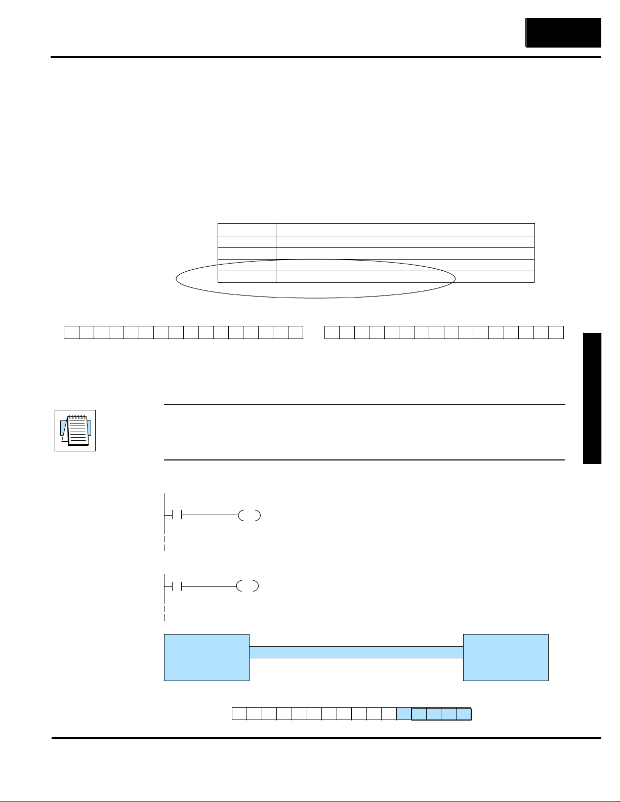
U
nde
r
s
t
andin
g
U
nde
r
s
t
andin
g
3--11
Pushbuttons and Lamps
(P.B.F1
)
The OP--640 has five user-defined pushbuttons. Pushbuttons may be used to begin
events or tasks within the PLC, such as start/stop control. This section describes
concepts of how to monitor and control the pushbuttons on your OP-panel.
Installation and Specifications
Pushbutton
Operation
MSB
Pushbutton
Example
The OP-panel pushbutton inputs are monitored for ON/OFF conditions in your PLC
ladder logic program. From a practical point of view we need to control and monitor
the bits in the status register on an individual basis. The OP--640 pushbuttons are
assigned to the first five bits of the Status Register (M+12). Examine the highlighted
status bits below which show each user-definable pushbutton.
M+10
M+11
M+12
M+13
Status Register
12131415 891011 4567 0123
F5 F1F2F3F4
The pushbutton example shown here is using DirectLOGIC PLC address
references. The equivalent instructions for other PLC productssupported are shown
in Chapter 5 of this manual.
NOTE: In this example we assume that the OP-panel is configured with a base
register of V2000. In this case, status register M+12 is V2014 which we will assume
has been mapped to V40600, the DirectLogic internal control relay memory.
Mapping details are discussed later in this chapter.
Bottom line data
Bottom line data 2 (for long BCD and floating point numbers)
Status register
Control register
LSB
MSB
12131415 891011 4567 0123
Control Register
LF2LF3BD L1L2L3LF1
LSB
the Features
the Features
C0
ON
(D2--250/D3 --350/D4--450 Only)
Direct bit register access
V2014.0
ON
C50
OUT
C50
OUT
Status Register
Bit 0: (F1)
M+12
M+12
C14C15C16C17 C10C11C12C13 C4C5C6C7 C0C1C3 C2
Status Register
OP--640
Status Register
In this example, C0 represents the pushbutton
No.1 (F1) via the mapping process.When pushbutton No.1 is pressed C0 is true and Coil C50
is energized.
Status Register (M+12) = V40600: C0 -- C17
PLC Program User Memory
V40600 =
C0 -- C17
M+6
F5 F2F3F4 F1
Page 37
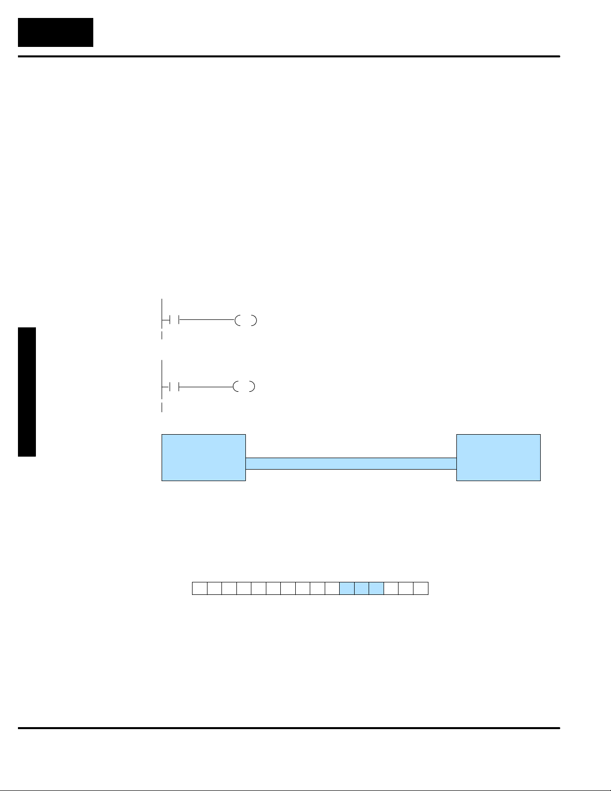
UnderstandingtheFeaturestheFeatures
3--12
Installation and Specifications
Pushbuttons Using
Direct Access to
Status Register
Bits
Pushbutton LEDs
Lamp Example
The DirectLogic D2--250/D3--350/D4--450 CPUs and the Allen-Bradley SLC 5/03
and 5/04 support instructions which provide individual status bits access. This is
called Bit-of-Word capability. For example, in the previous example, the ladder
logic for the D2--250/D3--350/D4--450 monitors the first bit of the status word directly.
Once again, our example assumes that we configured the OP-panel with a starting
base address of V2000.
There are LEDs located on each of the user defined pushbuttons, indicating
pushbutton status (ON or OFF). You may choose the pushbutton type (alternate or
momentary) while configuring your OP-panel. In the case of an alternating
configured pushbutton, the LED will change state each time the pushbutton is
pressed. With momentary configured pushbuttons the LED is ONonly as longas the
pushbutton is being pressed.
The lamp examples shown here are using DirectLOGIC PLC address references.
The equivalent instructions for other PLC products supported are shown in
Chaper 5.
C1
LAMP1
C20
OUT
ON
(DL250,DL350,DL 450 Only)
Direct bit register access
V2014.1
V2015.0
OUT
In this example, C1 represents the pushbutton
No.2 (F2) via the mapping process. When alter-
nating pushbutton No.2 is pressed internalControl Relay C20 is true and via mapping process
Control register Bit 0 (L1 Lamp) is energized.
* Control Register (M+13) = V40601: C20 -- C37
ON
OP-Control Register
M+13 C20 -- C37
Control registerM+13
PLC Program User Memory
V40601=Bit 0: (L1)
All lamps may be controlled using the concept shown above. You may use the Lamp
Flash option by controlling the appropriate Flash bit via the ladder logic program.
The example figure below demonstrates how to use the Control register Flash bits
(LF1, LF2, and LF3).
MSB
C34C35C36C37 C30C31C32C33 C24C25C26C27 C20C21C22C23
Control Register M+13
LF3 LF1
LF2BD L1L2L3
LSB
Page 38
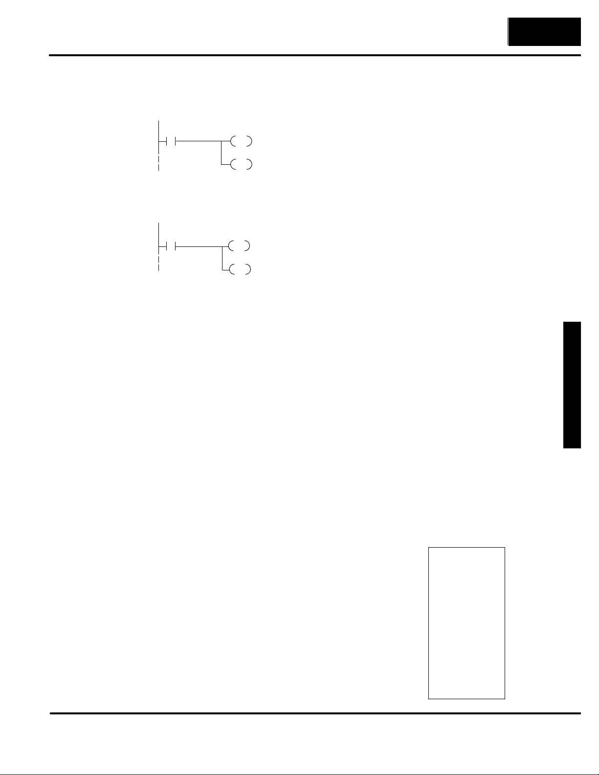
U
nde
r
s
t
andin
g
3--13
Installation and Specifications
Inthisexample,C2representsthepushbutton
Lamp Flash
The lamp flash examples shown here are using DirectLOGIC PLC address
references. The equivalent instructions for other PLC productssupported are shown
in Chapter 5.
C2
ON
(DL250/D3--350/D4 --450 Only)
Direct bit register access
V2014.2
ON
C21
OUT
C24
OUT
V2015.1
OUT
V2015.4
OUT
Memory Mapping Process
Each OP--640 is assigned 224 bits of PLC user memory which will be used as the
OP-panel database. The ladder logic program must access this assigned OP-panel
memory. Let’s take a closer look at this user memory and how it relates to the
OP-panel features.
OP Base
Register Memory
Definition
Operator Panel
Base Memory
As discussed earlier, regardless of which PLC product you are using the base
registers addressed M+0 through M+13 are formatted the same. In this manual,
when the terms M+0 through M+13 are used, this identifies which base register(s)
are affected for the topic being covered.
PLC user memory is assigned to each panel with the OP--WINEDIT configuration
software. For new OP-panels and add-on applications the programmer must define
fourteen 16-bit registers for PLC interface. Below is a figure showing memory layout
for DirectLOGIC DL05, DL105, DL205, D3--350, DL405 PLC’s and uses
V2000--V2015 for the OP--640 panel. See the next page for other PLC product
memory usage examples.
No.3 (F3) via the mapping process. When alter-
nating pushbutton No.3 is pressed internalControl Relay C21 and C24 are energized ON. This
process manipulates Control register bit 1 and
bit 4 which controls yellow lamp and flashing.
*Control Register (M+13) = V40601: C20--C37
the Features
You must reserve 224 bits (fourteen
16-bit registers or twenty-eight 8-bit
registers) which are used to process data
between the panel and your PLC. You
must configure the Base register for the
OP-panel. This base register address is
stored in the OP-panel memory.
CPU User’s memory
OP-- 640 Panel
Data Base
V2000
V2001
V2002
V2003
V2004
V2005
V2006
V2007
V2010
V2011
V2012
V2013
V2014
V2015
M+0
M+1 16 bits
M+2
M+3
M+4
M+5
M+6
M+7
M+8 16 bits
M+9
M+10
M+11
M+12
M+13
Total: 224 bits
16 bits
16 bits
16 bits
16 bits
16 bits
16 bits
16 bits
.
16 bits
16 bits
16 bits
16 bits
16 bits
Page 39
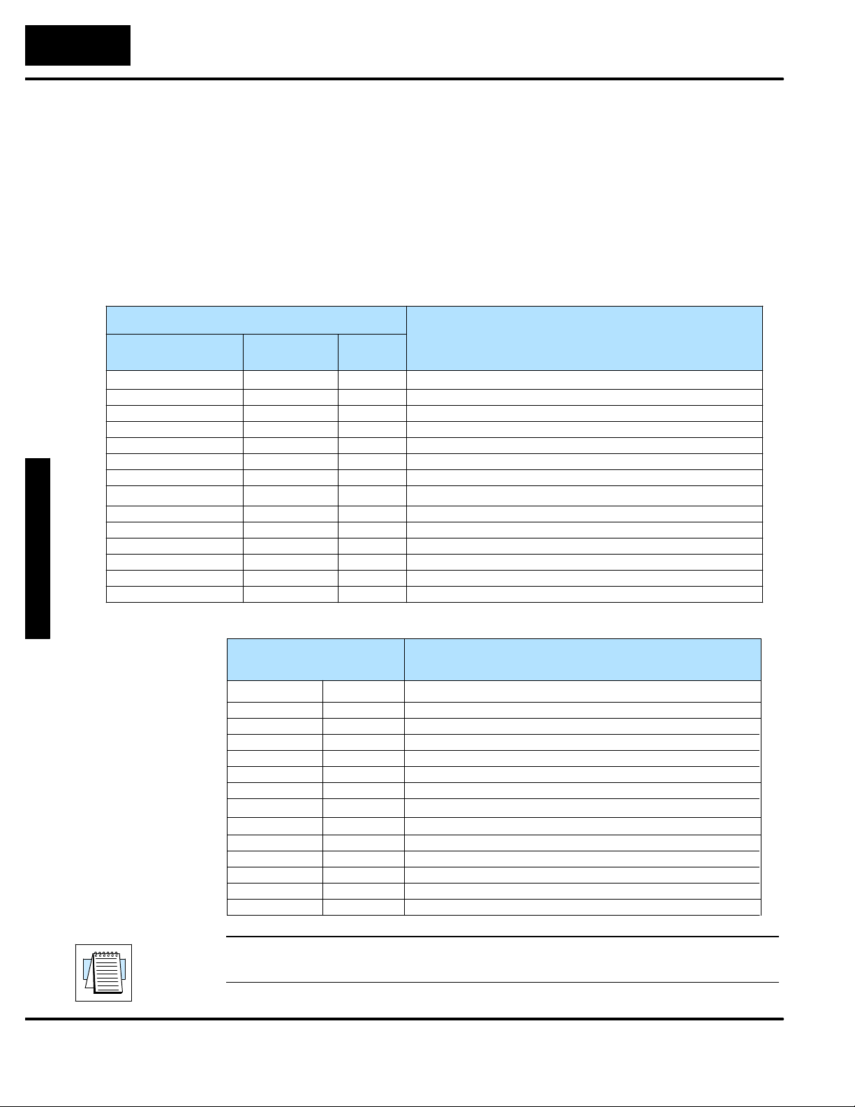
UnderstandingtheFeaturestheFeatures
3--14
Installation and Specifications
OP-PanelUse
r
Memor
y
Let’s examine the different address conventions for DirectLOGIC and
Allen-Bradley. For example, the DirectLOGIC address references are octal, and
the Allen-Bradley is decimal.
The DirectLOGIC DL05/DL105/DL205/D3--350/DL405 OP-panel address uses
V-memory registers which are 16-bit registers. The D3--330/340 CPUs use
reference assignments with 8-bit registers. This means that they require fourteen
8-bit registers for data handling. The Allen-Bradley memory is defined with a
reference (Nx) which represents the memory area, and (:n) which defines the word
within the memory area. Please refer to the appropriate CPU User manual for the
PLC product you are using.
DirectLOGIC PLCs
Example PLC Register Address
DL05/105/205/
D3--350/DL405
V2000
V2001
V2002
V2003
V2004
V2005
V2006
V2007
V2010
V2011
V2012
V2013
V2014
V2015
D3--330/
D3--340
R400/R401
R402/R403
R404/R405
R406/R407
R410/R411
R412/R413
R414/R415
R416/R417
R420/R421
R422/R423
R424/R425
R426/R427
R430/R431
R432/R433
Generic
M+0
M+1
M+2
M+3
M+4
M+5
M+6
M+7
M+8
M+9
M+10
M+11
M+12
M+13
Register
Function
Top line message selection
Second line message selection
Third line message selection
Bottom line message selection
Top line data
Top line data 2 (for long BCD and floating point numbers)
Second line data
Second line data 2 (for long BCD and floating point numbers)
Third line data
Third line data 2 (for long BCD and floating point numbers)
Bottom line data
Bottom line data 2 (for long BCD and floating point numbers)
Status register
Control register
Allen-Bradley SLC 500
Example PLC
Register Address
N7:0
N7:1
N7:2
N7:3
N7:4
N7:5
N7:6
N7:7
N7:8
N7:9
N7:10
N7:11
N7:12
N7:13
M+0
M+1
M+2
M+3
M+4
M+5
M+6
M+7
M+8
M+9
M+10
M+11
M+12
M+13
Top line message selection
Second line message selection
Third line message selection
Bottom line message selection
Top line data
Not used (see Note)
Second line data
Not used (see Note)
Third line data
Bottom line data
Not used (see Note)
Status register
Control register
Register
Function
Not used (see Note)
NOTE: While the OP--640 will display BCD Double and Floating Point numbers, it
does not support these functions when used with Allen--Bradley PLCs.
Page 40
U
nde
r
s
t
andin
g
3--15
DirectLOGIC User Memory Overview
D0--05
V-Memory
D1--130/D2 --230
V-Memory
D2--240
V-Memory
D4--430
V-Memory
Installation and Specifications
D2--250
D3--350
D4--440
V-Memory
D4--450
V-Memory
V1200
V7377
V40600
V40637
R016
R037
R400
R563
D3--330
R-Memory
V2000
V2377
V40600
V40617
R016
R037
R100
R106
R400
R563
R700
R767
D3--340
R-Memory
V2000
V3777
V40600
V40617
V1400
V7377
V40600
V40635
V1400
V7377
V10000
V17777
V40600
V40677
V1400
V7377
V10000
the Features
V37777
V40600
V40777
User Data Space available for OP-panels
Internal Relay Memory
DirectLOGIC PLCs use octal addressing, as indicated by the shaded areas.
Page 41
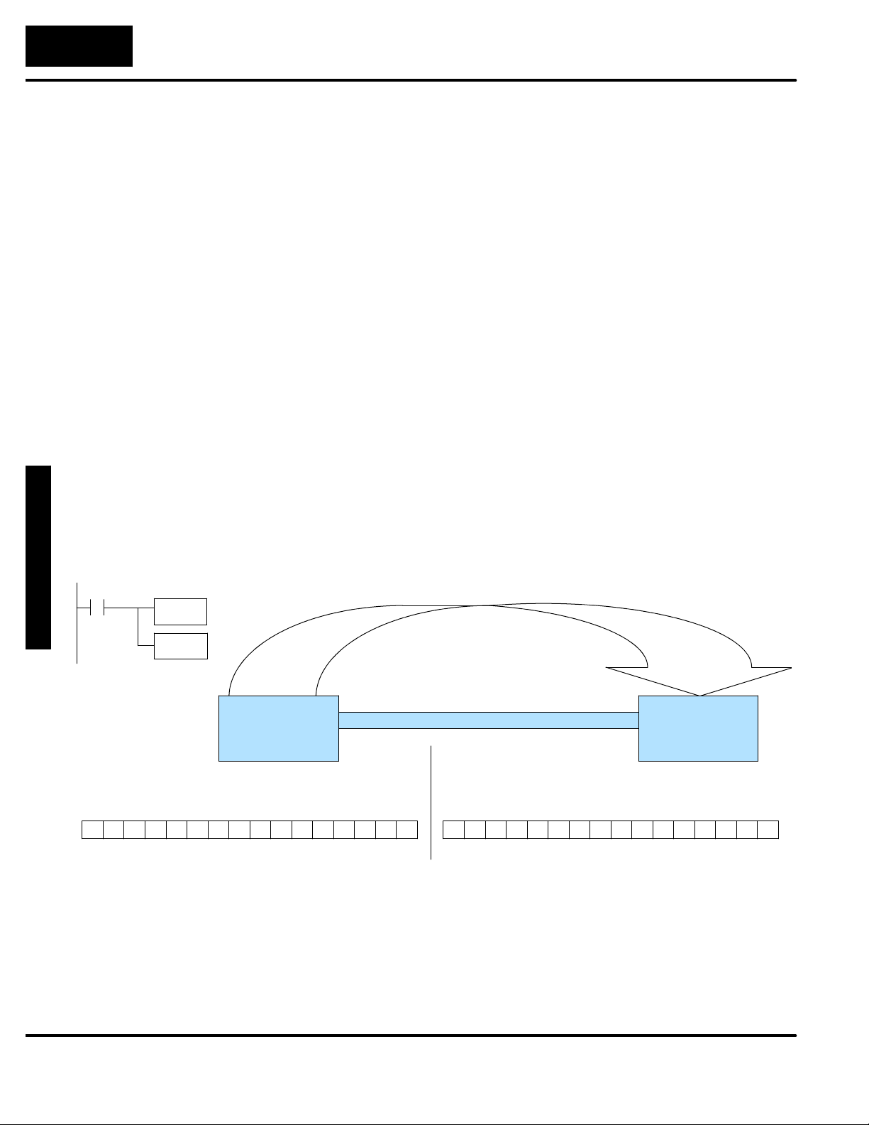
UnderstandingtheFeaturestheFeatures
3--16
Installation and Specifications
SP1(alwaysON)mapsOP
Mapping Operation
We explained earlier that the PLC and OP-panel must exchange data on a bit-level
basis. For DirectLOGIC controllers, the OP-panel Status Register (M+12) must be
mapped into internal control relays such as C0, C1, etc (and the control relays
C20--C37 must be mapped into the Control Register, M+13). This allows direct
access to the Status bit register and the Control bit register. You must execute
mapping every CPU scan in order to update data between the OP-panel and PLC.
The following examples assume the OP-panel starting base-register (M+0) is
assigned to word register V2000. For example, the DL05, DL105, DL205, D3--350,
and DL405 CPUs have internal control relays starting at register V40600. They are
designated as C0, C1, etc. Mapping updates status data (M+12) into base register
V2014 and control data (M+13) into base regiser V2015 with each PLC scan.
Mapping Examples (DL05, 105, DL205, D3--350, and DL405)
Mapping the Status
Register
register V2014 to
V40600:C0 --C17.
SP1
LD
ON
OP--640
V2014
OUT
V40600
12131415 891011 4567 0123 C14C15C16C17 C10C11C12C13 C4C5C6C7 C0C1C3 C2
The figure below demonstrates how the OP-panel status register is mapped to user
memory for bit manipulation. Notice the sixteen bits in the status register are loaded
into the Internal Control Relays C0--C17. These control relays are used within the
ladder logic program for monitoring pushbuttons and coordinating data entry
control.
Mapping the Status Register
OP-panel
Register
M+12
F5 F1F2F3F4
M+12
M+12
Status register
PLC Program User Memory
Internal
Control
Relays
V40600 =V2014
C0 -- C17
F5 F1F2F3F4
Page 42
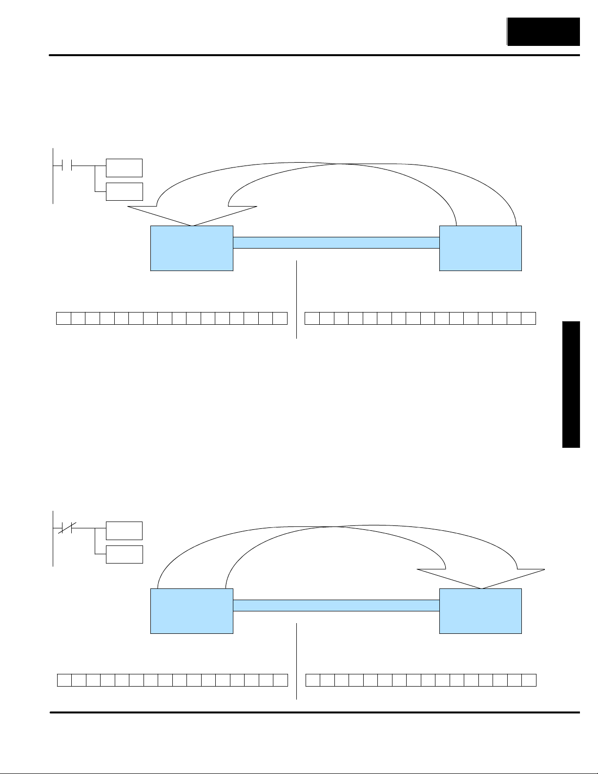
U
nde
r
s
t
andin
g
3--17
Installation and Specifications
SP1(alwaysON)mapsOPregister
NotC374(alwaysONafterfirstscan)
Mapping the Control
Register
The figure below demonstrates how the Internal Control Relays C20--C37 are
mapped to the OP-panel control register. Notice the sixteen bits in the Internal
Control Relays C20--C37 are loaded into the control register. These control relays
function as outputs for the Lights.
V40601 (C20 --C37) to V2015.
SP1
LD
ON
V40601
OUT
V2015
OP-panel
Register
Mapping the Control Register
M+13
Status register
M+13
OP--640
12131415 891011 4567 0123 C34C35C36C37 C30C31C32C33 C24C25C26C27 C20C21C23C22
LF2LF3BD L1L2L3LF1
M+13
Mapping Example (D3--330/340)
Internal
Control
Relays
V40601 =V2015
C20 -- C37
PLC Program User Memory
LF2LF3BD L1L2L3LF1
the Features
Mapping the Status
Register
C374
Note that
DSTR and
DOUT are
16-bit
instructions.
maps OP register R430/R431 to R16/R17.
DSTR
ON
R430
DOUT
R16
OP--640
12131415 891011 4567 0123
Unlike the DL05, DL105, DL205, D3--350, and DL405 mapping examples, the
D3--330/340 CPUs use 8-bit words. So it takes two 8-bit words for each mapped
memory location because each mapped memory location needs sixteen
consecutive bits. We will assume that R400 was used as the base register address
and we want the mapping to start at R16 for the status register.
The figure below demonstrates how the OP-panel status register is mapped to user
memory for bit manipulation. Notice the sixteen bits in the status register are loaded
into the Internal Control Relays C160--C177. These control relays monitor
pushbuttons and coordinate data entry control.
Mapping the Status Register
OP-panel
Register
R430/R431
M+12
M+12
M+12
F5 F1F2F3F4 F5 F1F2F3F4
Status register
C176
C174
C175
C177
C172
PLC Program User Memory
C166
C170 C160
Internal
Control
Relays
R16/R17
C162C164
C163C165C167C171C173
C161
Page 43
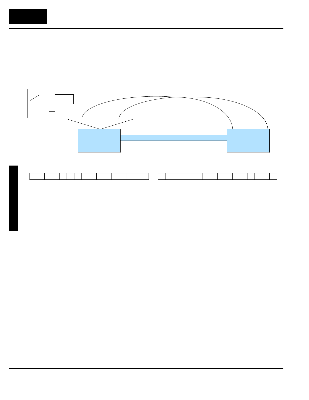
UnderstandingtheFeaturestheFeatures
3--18
Installation and Specifications
NotC374(alwaysONafter
Mapping the Control
Register
first scan) maps Control
Relays R20/R21 to OP
registers R432/R433.
C374
DSTR
ON
Note that
DSTR and
DOUT are
16-bit
instructions.
R200
DOUT
R432
OP--640
12131415 891011 4567 0123
The figure below demonstrates how the Internal Control Relays are mapped to the
OP-panel control register. Notice the sixteen bits in the Internal Control Relays
C200--C217 are loaded into the control register. These control relays function as
outputs for the Lights.
Mapping the Control Register
OP-panel
Register
R432/R433
M+13
M+13
M+13
LF2LF3BD L1L2L3LF1 LF2LF3BD L1L2L3LF1
Control register
C216
C214
C215
C217
C212
PLC Program User Memory
C206
C210 C200
Internal
Control
Relays
R20/R21
C202C204
C203C205C207C211C213
C201
Page 44

4
Configuring Your
Operator Panel
In This Chapter. . . .
— Preparing for Configuration
— How to Configure Your Panel
Page 45
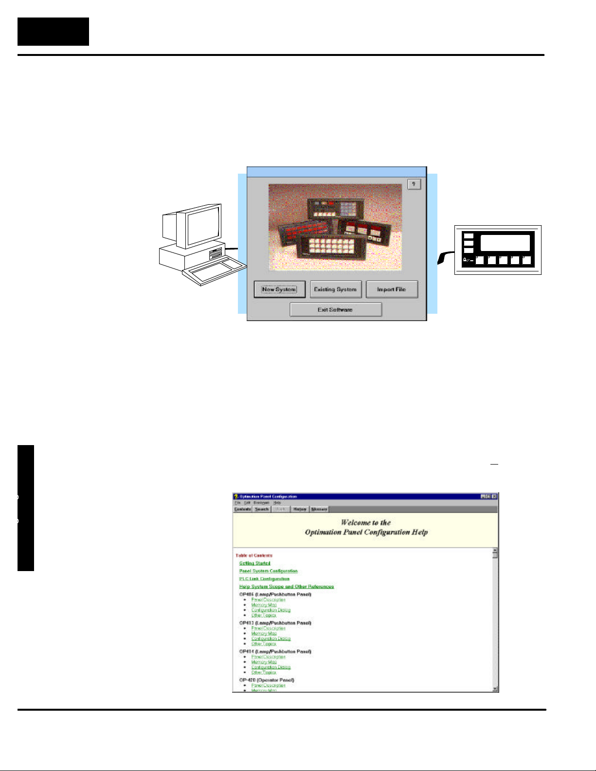
Y
ourPane
l
4--
2
Configuring Your Operator Panel
HELPScreens
Preparing for Configuration
OP--WINEDIT
Software
More about
OP--WINEDIT
The OP--640 is configured with software running on a personal computer. This
software is available through Automationdirect.com and is referred to as
OP--WINEDIT configuration software.
The OP--WINEDIT configuration software allows you to configure OP--panel
applications, as well as download (write to panel) and upload (read from panel) the
configurations. Use this software to configure your communication link, select
pushbutton control, and enter operator display messages. Order the software using
part number OP--WINEDIT. The OP--640 panel requires version 2.3 or later.
The OP--WINEDIT software provides Help windows which supply instructions for
performing all necessary configuration tasks. Should you have problems
understanding how to program your panel, refer to these built-in Help windows. To
access the Help windows, point and click on the Help menu and choose Using help,
or click on the [?] icon located near the top of the main configuration window.
HELP Screen
Menu
Operator Panel
Page 46

O
p
erato
r
P
ane
l
4--
3
Configuring Your Operator Panel
Yourpersonalcomputermustmeetthefollowin
g
Application
Worksheets
Computer System
Requirements
To prepare your application, use the Application Worksheets which are provided
in Appendix A of this manual. The example worksheets will helpyou configurethe
OP--640 panel. The blank worksheets can be photocopied and used in planning
your own applications.
minimum requirements:
3 IBM type 386 or above
3 Windows 3.1 or later,
including Windows 95, 98 or NT
3 1 meg of hard drive
3 1 meg of RAM
How to Configure Your Panel
Follow these steps to configure your OP--640 operator panel.
Step 1
Step 2
Load OP--WINEDIT -- If you are not already using the configuration software orhave
an older version, you must install version 2.3 or later (if you are using an older version
of OP--WINEDIT you can obtain an upgrade at our web site). The software is
provided on one 3-1/2 inch high-density diskette and comes with its own manual. Here
are brief installation instructions.
S Place the installation disk into your computer’s floppy drive (usually
either drive A or drive B).
S Open Microsoftt Windows (3.1 or above). For Microsoft Windows 95 or
NT the Start/Run program task bar is located at the bottom left portion
of your screen. For Microsoft Windows 3.x versions select File/Run
from the Program Manager screen.
S Select Run, and a pop-up window appears. Type in the path for the
drive in which you have placed the setup disk and designate the file
setup. Click on OK when you are finished.
Connect Panel to PC -- Connect the OP--640 to your personal computer using the
OP--ACBL--1 configuration cable.
OptiMate
OP-WINEDIT
Operator Panel
Page 47
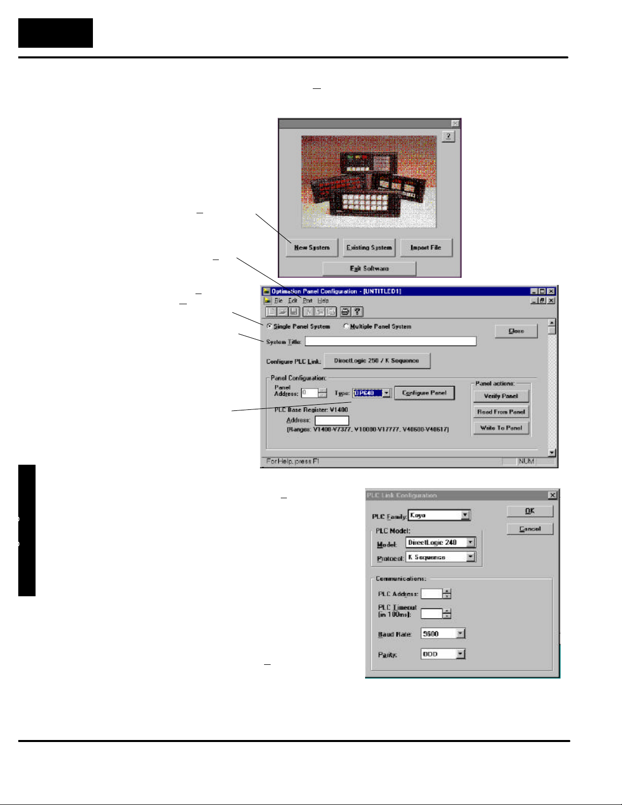
Y
ourPane
l
4--
4
Configuring Your Operator Panel
SelectConfigurePLCLin
k
--Herei
s
Step5
Step 3
Step 4
Open OP--WINEDIT -- Select New System.
Start Configuring Your Panel -- Start by filling in these parameters:
Select New System
Select PC Port
Select Single
or Multiple
Panel System
Enter a title that
you will save this
configuration as.
Select OP640
42000
where you define protocol items such
as PLC address, baud rate and parity.
Enter the appropriate parameters for
your PLC. The following table provides
the necessary information for most
Operator Panel
DirectLOGIC controllers. For other
PLC families, reference that product’s
user manual to determine the port
1
communications capabilities.
3
During configuration, make sure that
your address and communications
parameters match the PLC port
settings. The PLC Timeout works like
this: When the panelsends a message
to the PLC and does not receive a
response or does not understand the
response, it will wait the time-out
period before resending the message.
Page 48
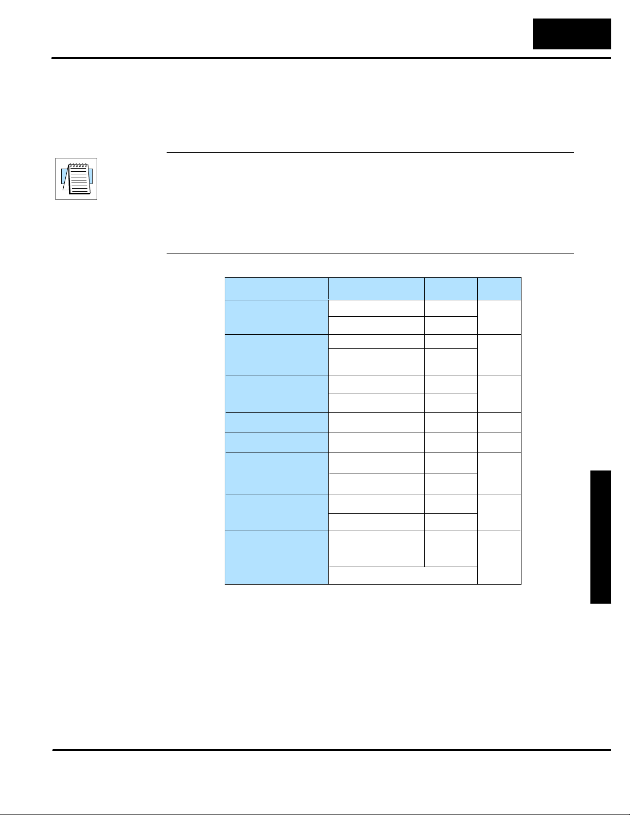
O
p
erato
r
P
ane
l
4--
5
Configuring Your Operator Panel
You also have several ports which can be used to connect your communications
cable. Some of these ports have fixed PLC address assignments, and some do not.
The ports which allow configuring the PLC addresses can be set to a unique
address, ranging from 1 through 90. Refer to your User Manual for specific
information on the ports of your PLC.
NOTE: For A--B PLCs, connect to Channel 0 (bottom port), using DF1 full duplex.
Additionally, the A-B software allows you to set the bottom port to a unique PLC
address. The software default is PLC Address 1. You must select CRC error
detection and match the address on the configuration screen to the address you
have assigned. This port must also be configured for either 4800 or 9600 baud. No
other baud rates are supported for communicating between the OP--panels and an
A-B PLC. Since the A-B software uses a default baud rate of 1200, you must change
the settings.
PLC Model Port/Baud Rates Parity
DL05
DL105/D2--230/
D2--240
(DL240 only)
D2--250
Bottom &Top
D3--350
D4--430/440
D4--450
Port 1
Port 2
Top
Bottom
Top
Bottom
DCU Only
Top
Bottom
Top
Bottom
DB15
DB25
RJ12
9600
9600
9600/19.2k
9600
9600/19.2K
4800/9600/19.2k
9600
4800/9600/19.2K
9600
9600/19.2k Odd/None
9600
9600/19.2k Odd/None
9600/19.2k Odd/None
Odd
Odd/None9600/19.2K
Odd
Odd/None
Odd/None
Odd/None
Odd/NoneD3--330 4800/9600/19.2k
Odd/NoneD3--340
Odd/None
Odd
Odd
Odd
Stop
Bit
1
1
1
1
1
1
Operator Panel
1
1
Step 6
Select the Base Register Address -- This step is very important because it
establishes the link in your PLC memory to the panel. Chapter 3, Understanding the
Features, describes the mapping process. Once you are familiar with the mapping
process and you know which memory block in your PLC to use (refer to the user
manual for your PLC), enter your selection.
If you choose Allen-Bradley as your PLC Type, you must enter the PLC File Number
in addition to a Base Register Address. You must expand the memory map in the
Allen-Bradley PLC to include all registers being used by the OP-panel.The panel will
only recognize integer file types N7 and user-defined file types N9 through N255.
Enter the number only and not the prefix N. The Base Register Address is any
number between 0 and 255.
Page 49
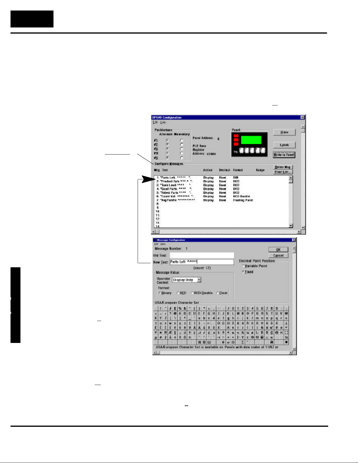
Y
ourPane
l
4--
6
Configuring Your Operator Panel
Step 7
Configure the Panel Features -- These features are discussed in detail in Chapter
3, but they include:
S Pushbutton Configuration -- The pushbuttons can be configured as
either Momentary or Maintained (alternate ON/OFF). Momentary
pushbuttons remain ON as long as they are pressed, while Maintained
pushbuttons retain their status (ON or OFF) until the next time they are
pressed.
S Messages -- Enter all messages using the Configure Messages window.
Select Configure
Messages
For example, to enter
message #1, place
curser by the “1.”
area and double-click.
This screen appears,
allowing you to enter
the message. Select
OK when message is
Operator Panel
Step 8
written.
Save and Download -- Connect the OP--ACBL--1 configuration cable to the panel
and set the RUN/PGM Switch to ON (PGM) and the TERM switch to OFF. Select
Write to Panel to download the configuration to your panel. When the program is
finished downloading, wait a few seconds before disconnecting the configuration
cable. When downloading to OP-panels which have already been configured, first
clear the message list (Clear List) before loading the new configuration. This
removes old messages which may reside within the OP-panel’s memory.
Remember to save your configuration program before closing OP--WINEDIT.
Page 50

5
Programming
Examples
In This Chapter. . . .
— Examples Using DirectLogic PLCs
— DL05/105/DL205/D3--350/DL405 Examples
— D3--330/340 Examples
— Allen-Bradleyt SLC 5103--5105 and Micrologix Examples
— Troubleshooting
Page 51
Y
ourPanelProgramming
5--
2
Programming Examples
FamilyCPUControlRelayRegister
s
D2--240V2000--V3777
D3--340R400--R563an
d
D4--440V1400--V7377an
d
Examples Using DirectLOGIC PLCs
Register Usage
The OP--WINEDIT configuration software allows you to configure a panel to use a
block of registers at a starting value that you define. For a DL05, DL105, DL205,
D3--350 or DL405 CPU the recommended memory to use is the general purpose
data words starting at V2000. For the 305 family (except the D3--350) the
recommended memory is the registers beginning at R400. Any block of registers
within the data word range can be used.
The first eleven PLC registers in the block used by the OP--640 panel are used for
numeric information, and this makes them ideally suited for the general purpose
data registers. The M+12 and M+13 registers use individual bits for pushbutton
status and light control, making it better suited for the control relay register range of
memory. The solution to this minor conflict is to define the base register address in
general purpose data register memory and place a rung in your PLC program to
copy the last register to a control relay register (we show you how to do this later).
The following table lists the data word registers for DirectLOGICt CPUs.
Data Word Registers for DirectLOGICt PLCs
DirectLOGICt DL05 D0-- 05 V1200-- V7377
DirectLOGICt DL105 F1--130 V2000--V2377
DirectLOGICt DL205 D2--230 V2000--V2377
D2-- 250 V1400--V7377 and
V10000-- V17777
DirectLOGICt DL305 D3--330/D3--330P R400-- R563
D3-- 340 R400--R563 and
R700-- R767
D3-- 350 V1400--V7377 and
V10000-- V17777
DirectLOGICt DL405 D4--430 V1400--V7377
D4-- 440 V1400--V7377 and
V10000-- V17777
D4-- 450 V1400--V7377 and
V10000-- V37777
Examples
Page 52
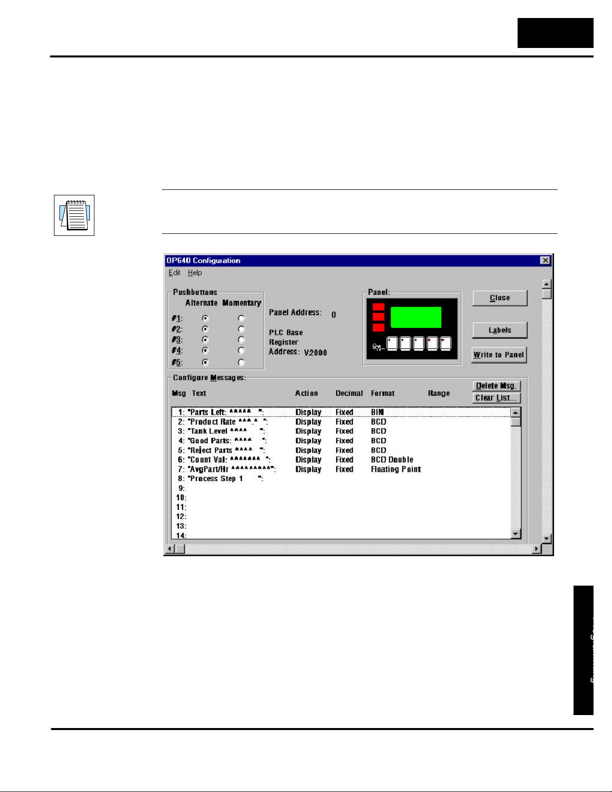
O
p
erato
r
P
ane
l
P
r
o
gra
m
m
i
n
g
5--
3
Programming Examples
Definingthe
StatusRegiste
r
DL05, DL105, DL205, D3--350 and DL405 Examples
The following examples assume that the OP--640 is configured for a base address of
V2000. When configuring the panel, use the configuration data and messages
shown in the following figure.
NOTE: The Example Worksheet in Appendix A also has the configuration data and
messages needed for these examples. The example shows how to plan your
configurations.
BIN
BIN
BIN
BIN
BIN
BIN
Examples
Page 53
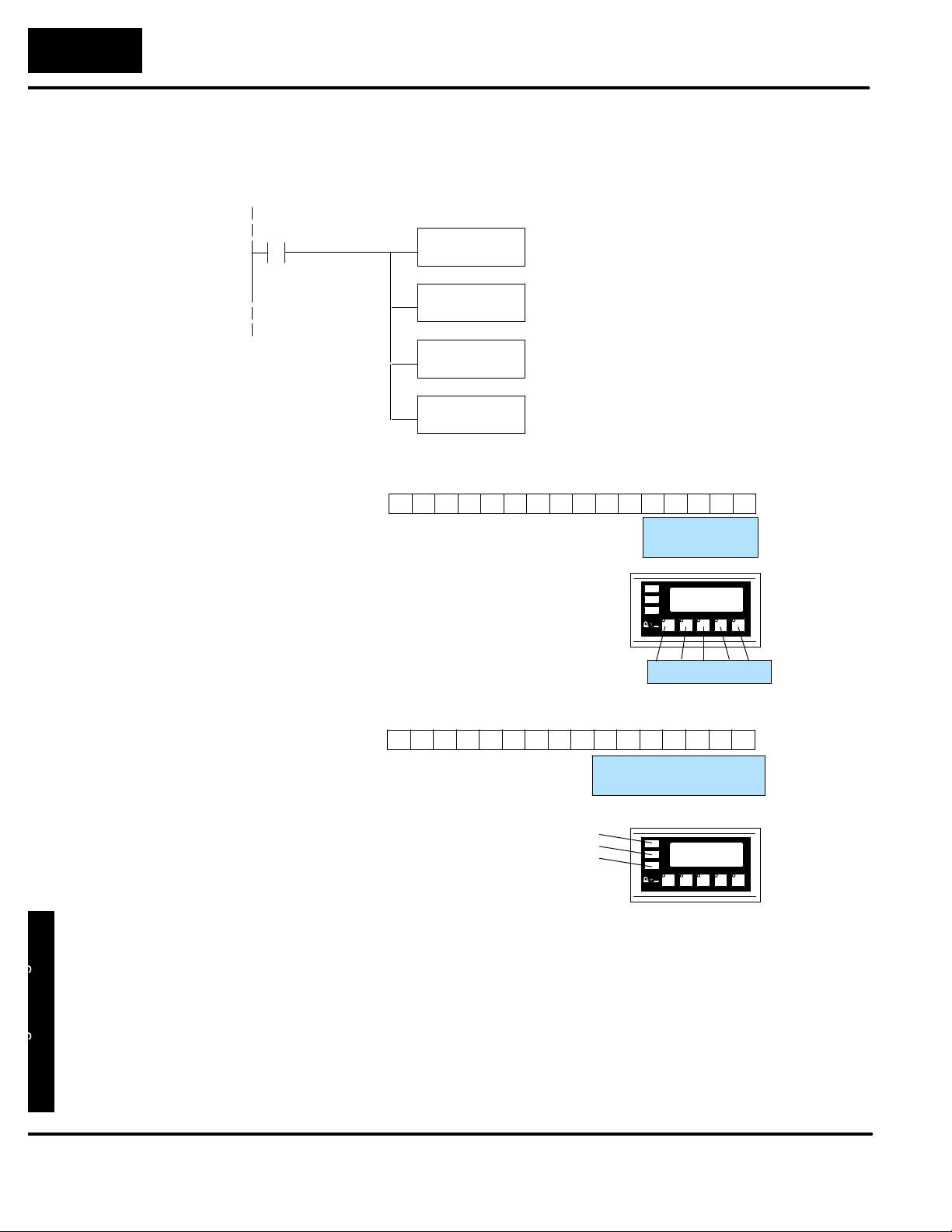
Y
ourPanelProgramming
5--
4
Programming Examples
RegisterV4060
0
Place the following program rung in the program to copy the status register to
memory location V40600 and copy V40601 to the control register. With this rung
placed in the PLC program, the status and control bits will be control relays.
SP1
Status Register
Control Register
LD
V2014
OUT
V40600
LD
V40601
OUT
V2015
MSB
Bit
As you can see, control relays C0--C4
will be associated with pushbuttons F1--F5.
MSB
Bit
Control relays C20-- C22 will be associated
with lamps L1--L3.
Control relays C23-- C25 will control
L1-- L3 flashing. C26 controls whether
pushbuttons F1--F5 beep when pressed.
12131415 891011 4567 0123
12 1113141516 910 5678 1234
12131415 891011 4567 0123
12 1113141516 910 5678 1234
Status register
Control register
Register V40601
LSB
C4
F5
F1 F2 F3 F4 F5
C24
C25C26
LF2
BD
LF3
L1
L2
L3
C0C1C2C3
F1F2F3F4
LSB
C20C21C22C23
L1L2L3LF1
Examples
Page 54

O
p
erato
r
P
ane
l
P
r
o
gra
m
m
i
n
g
5--
5
Programming Examples
UsingaFunctio
n
Butto
n
The five function buttons will appear as control relay coils in your program (assuming
the register copy rung shown previously is in the program).
C0
C1
C2
C3
Y1
OUT
F1
Y2
OUT
F2
Y3
OUT
F3
Y4
OUT
F4
This rung turns on output Y1 when pushbutton
F1 is active.
This rung turns on output Y2 when pushbutton
F2 is active.
This rung turns on output Y3 when pushbutton
F3 is active.
This rung turns on output Y4 when pushbutton
F4 is active.
C4
Y5
OUT
F5
This rung turns on output Y5 when pushbutton
F5 is active.
Examples
Page 55
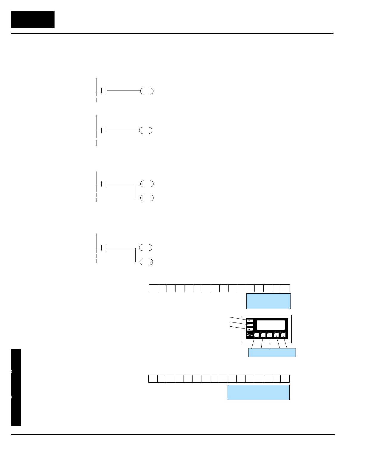
Y
ourPanelProgramming
5--
6
Programming Examples
Inthisexample,C2representsthepushbutton
LightingaLamp
Lighting a lamp simply requires activating thecontrol relayassociated withthe lamp.
The following example will light the first lamp when relay C1 is on. Remember to
place the register copy rung shown previously in the program.
Flashing a Lamp
C1
LAMP1
C20
OUT
ON
(DL250,DL350,DL 450 Only)
Direct bit register access
V2014.1
V2015.0
OUT
In this example, C1 represents the pushbutton
No. 2 (F2) via the mapping process. When alter-
nating pushbutton No. 2 ispressed internal Control Relay C20 is true and via mapping process
Control register Bit 0 (L1 Lamp) is energized.
* Control Register (M+13) = V40601: C20 -- C37
ON
Flashing a lamp simply requires activating the lamp control relay (to turn the lamp
on) and the flash control relay.
C2
ON
(DL250/D3--350/D4 --450 Only)
Direct bit register access
V2014.2
ON
Status Register
C21
OUT
C24
OUT
V2015.1
OUT
V2015.4
OUT
Bit
MSB
No. 3 (F3) via the mapping process. When alter-
nating pushbutton No. 3 ispressed internal Control Relay C21 and C24 are energized ON. This
process manipulates ControlRegister bits 1and
4 which controls lamp L2 on/off and L2 flashing
(LF2).
*Control Register (M+13) = V40601: C20--C37
Register V40600
12131415 891011 4567 0123
12 1113141516 910 5678 1234
C4
F5
LSB
C0C1C2C3
F1F2F3F4
L1
L2
L3
Control relays C0-- C4 will be associated
with pushbuttons F1--F5.
MSB
Bit
Control Register
Control relays C20-- C22 will be associated with
lamps L1--L3 and C23--C25 will control L1--L3
Examples
flashing. C26 controls whether pushbuttons
F1-- F5 beep when pressed.
12131415 891011 4567 0123
Register V40601
12 1113141516 910 5678 1234
BD
F1 F2 F3 F4 F5
C24
C25C26
LF2
LF3
LSB
C20C21C22C23
L1L2L3LF1
Page 56
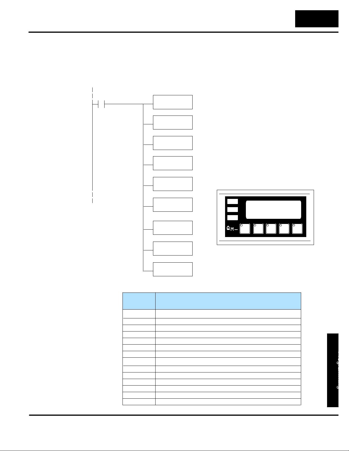
O
p
erato
r
P
ane
l
P
r
o
gra
m
m
i
n
g
O
p
erato
r
P
ane
l
P
r
o
gra
m
m
i
n
g
5--
7
Programming Examples
Displayin
g
Message
s
The following example shows two messages being displayed. The example
assumes that the messages shown earlier are entered, and shows two messages
that will be displayed as long as C100 is on. The second line is displaying message
#4 and the bottom line is displaying message #8. The top and third lines use data
message display #140, which has been configured as a blank text message.
C100
LD
K4
OUT
V2001
LD
K8
OUT
V2003
LD
V3000
OUT
V2006
LD
K140
OUT
V2000
OUT
V2002
This selects message #4 to be displayed in the
second line.
This selects message #8 to be displayed in the
bottom line.
This puts data from V3000 (235 in this example)
into the second line data field (^^^^).
Good Parts: 235
Process Step 1
The last three instructions select message #140
(blank text) and loads it into both the top and third
lines to blank those lines.
PLC Register
FunctionRegister
V2000
V2001
V2002
V2003
V2004
V2005
V2006
V2007
V2010
V2011
V2012
V2013
V2014
V2015
Top line message selection
Second line message selection
Third line message selection
Bottom line message selection
Top line data
Top line data 2 (for long BCD and floating point numbers)
Second line data
Second line data 2 (for long BCD and floating point numbers)
Third line data
Third line data 2 (for long BCD and floating point numbers)
Bottom line data
Bottom line data 2 (for long BCD and floating point numbers)
Status register
Control register
Examples
Examples
Page 57
Y
ourPanelProgramming
5--
8
Programming Examples
.
DisplayingBinar
y
Numbers
This example is similar to the previous example, except that it uses a binary number
in the top display. The top line uses data display message #1, which has been
configured as a binary display message. The data for the top data field is number
56432 (from V2200). The third line is text message #8. The second and bottom lines
use message #140 which has been configured as a blank text message.
C101
LD
K1
OUT
V2000
LD
K140
OUT
V2001
OUT
V2003
LD
K8
OUT
V2002
LD
V2200
This selects message #1 to be displayed in the top line
This selects message #140 to be displayed in the
second and bottom lines.
This selects message #8 to be displayed in the
third line.
This puts binary value from V2200 (56432 in this
example) into the top line data field (^^^^^).
OUT
V2004
Parts Left: 56432
Process Step 1
Examples
Page 58
O
p
erato
r
P
ane
l
P
r
o
gra
m
m
i
n
g
5--
9
Programming Examples
DisplayingBCD
DoubleNumbers
This example is similar to the previous example, except that it uses a BCD Double
number in the bottom line display. The bottom line uses data display message #6,
which has been configured as a BCD Double display message. The data for the
bottom line data field is from V3002 and V3003. V3002 contains the four least
significant digits while V3003 contains the four most significant digits. The top line is
text message #8. The second line displays message #3. The datafor the second line
BCD message comes from register V2100. The third line uses message #140, which
has been configured as a blank text message.
C102
LD
K8
OUT
V2000
LD
K3
OUT
V2001
LD
V2100
OUT
V2006
LD
K140
OUT
V2002
This selects message #8 to be displayed in the top line.
This selects message #3 to be displayed in the
second line.
This puts data from V2100 (1935 in this example)
into the second line data field.
This selects message #140 (blank) to be displayed in
the third line.
LD
K6
OUT
V2003
LDD
V3002
OUTD
V2012
This selects message #6 to be displayed in the
bottom line.
This puts BCD Double number from V3002
(64197324 in this example) into the bottom line
data field.
Examples
Process Step 1
Tank Level: 1935
CountVal: 64197324
Page 59
Y
ourPanelProgramming
5--10
Programming Examples
Displayin
g
Floating Point
Numbers
Example 1
This example uses a floating point number in the third line display message. The
third line uses data display message #7, which has been configured as a floating
point display message. Since the data is a floating point number, it uses two 16-bit
registers. The two registers have to be looked at together, not individually, for the
data to be understandable. In this example, the data is a constant number (168932)
which is loaded into the third line data display registers using an LDR (load real
number) instruction. The top and bottom lines use message #140, which has been
configured as a blank text message. The second line is text message #8.
C103
LD
K140
OUT
V2000
OUT
V2003
LD
K8
OUT
V2001
LD
K7
OUT
V2002
LDR
R168932
This selects message #140 (blank) to be displayed in
the top and bottom lines.
This selects message #8 to be displayed in the
second line.
This selects message #7 to be displayed in the
third line.
This puts the floating point value 168932 into the
third line data field. Notice that the displayed value
is truncated.
OUTD
V2010
Process Step 1
Avg Part/Hr +1.69E+05
Examples
Page 60
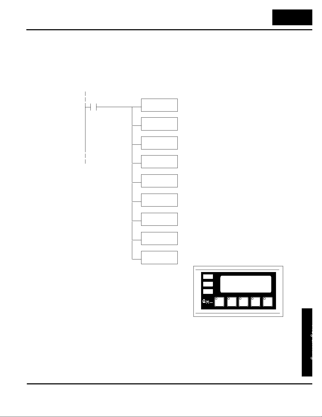
O
p
erato
r
P
ane
l
P
r
o
gra
m
m
i
n
g
5--11
Displayin
g
Floating Point
Numbers
Example 2
Programming Examples
This example is similar tothe previousone, except that it gets its value from two PLC
registers instead of a constant value. The third line uses data display message #7,
which has been configured as a floating point display message. Remember, floating
point numbers require two 16-bit registers and they must be read together. In this
example, the data is loaded from V3010 and V3011 using an LDR(load real number)
instruction to the third line display registers V2010 and V2011. The top and bottom
lines use message #140, which has been configured as a blank text message. The
second line uses message #8, a text message.
C104
LD
K140
OUT
V2000
OUT
V2003
LD
K8
OUT
V2001
LD
K7
OUT
V2002
LDR
V3010
This selects message #140 (blank) to be displayed in
the top and bottom lines.
This selects message #8 to be displayed in the
second line.
This selects message #7 to be displayed in the
third line.
This puts the floating point value from V3010 and
V3011 into display registers V2010 and V2011.
OUTD
V2010
Process Step 1
Avg Part/Hr +1.69E+05
Examples
Page 61
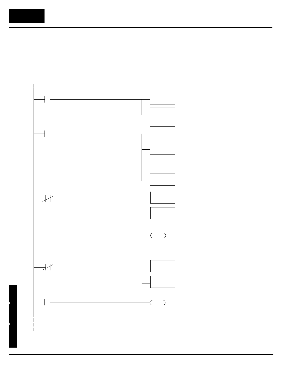
Y
ourPanelProgramming
5--12
Programming Examples
Example
Example Using D3--330/340
The following example assumes that the OP--640 is configured for a base address of
R400/R401. When configuring the panel, enter themessages shown in the previous
section for the DL05, DL105, DL205, D3--350 and DL405 examples.
IO0
DSTR
K1
F50
Displaying Messages
This rung displays message #1 in the top
display line.
IO3
First Scan
C374
C200 IO30
DOUT
R400
DSTR
K2
DOUT
R402
DSTR
K6739
DOUT
R414
DSTR
R430
DOUT
R20
OUT
F60
F50
F60
F50
F60
F50
F60
This rung displays message #2 and BCD data
in the second display line.
Second line message.
Second line data.
This rung remaps the status register
(pushbuttons) into control relays R20/21.
Pushbutton Example
This rung allows pushbutton F1 to turn on
output IO30.
First Scan
C374
IO2 C220
DSTR
DOUT
OUT
R22
R432
F50
F60
This rung remaps control relays R22/23 into
the control register (lamps).
Lamp Example
This rung allows input IO2 to turn on
lamp L1.
Examples
Page 62
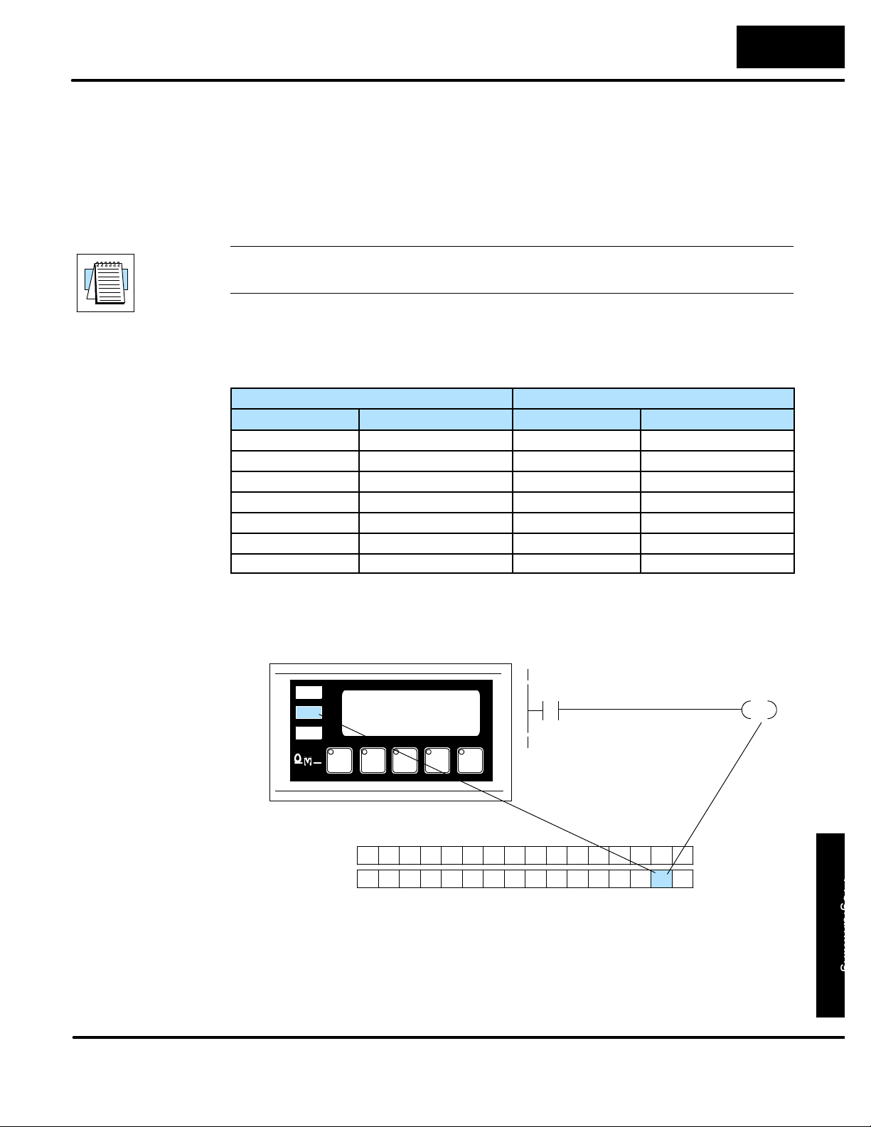
O
p
erato
r
P
ane
l
P
r
o
gra
m
m
i
n
g
5--13
Programming Examples
BitLocationBitLocatio
n
LightingaLamp
Allen-Bradleyt SLC 5/03 & 5/04 and Micrologix Examples
Interfacing to A-B
Memory
OptiMate panels interface to Allen-Bradley SLC 5/03 & 5/04 and Micrologix PLCs via
integer file type N. The 5/03 and 5/04 have file type N7 as standard. Other “N” type
files can be created. The Micrologix has a fixed file type N7. Please see A-B
documentation for information on setting up and using “N” type files.
NOTE: When using an OP--640 with an Allen-Bradley PLC, always be sure that at
least fourteen words of memory are allocated to allow proper communications.
All of the examples shown assume the OP--640 has been configured (using
OP--WINEDIT) for a file number N7 and base register address 0. With this
configuration, the status register will be at N7:12 and the control register will be at
N7:13. This table relates status register and control register bits to their N7 locations.
Status Register Control Register
F1 N7:12/0 L1 N7:13/0
F2 N7:12/1 L2 N7:13/1
F3 N7:12/2 L3 N7:13/2
F4 N7:12/3 L1F N7:13/3
F5 N7:12/4 L2F N7:13/4
L3F N7:13/5
BD N7:13/6
Lighting a lamp simply requires activating thecontrol relayassociated withthe lamp.
This example will light lamp L2 when input I:2/12 is active.
Lamp L2
N7:13
1
L2
Bit
Status Register
Control Register
MSB
I:2
12
12131415 891011 4567 0123
F5 F1F2F3F4
L3F
L2FBD L1L2L3L1F
LSB
Examples
Page 63
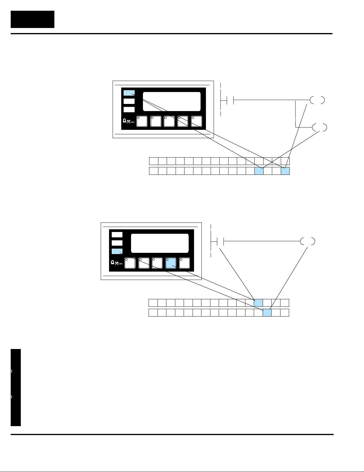
Y
ourPanelProgramming
5--14
Programming Examples
FlashingaLampUsingaFunction
Butto
n
Flashing a lamp simply requires activating the control relay to turn on the lamp and
the flash control relay. This example will flash lamp L1 when input I:2/12 is active.
L1
Bit
Status Register
Control Register
MSB
I:2
12
12131415 891011 4567 0123
F5 F1F2F3F4
LF3
LF2BD L1L2L3LF1
LSB
Lamp L1
N7:13
0
Flash LF1
N7:13
The five function buttons will appear as control relay coils in your program. This
example turns on lamp L3 (N7:13/2) when button F4 (N7:12/3) is active.
Lamp L3
N7:I3
2
L3
N7:12
Pushbutton F4
3
3
F4
Bit
Status Register
Control Register
MSB
12131415 891011 4567 0123
F5 F1F2F3F4
LF3
LF2BD L1L2L3LF1
LSB
Examples
Page 64
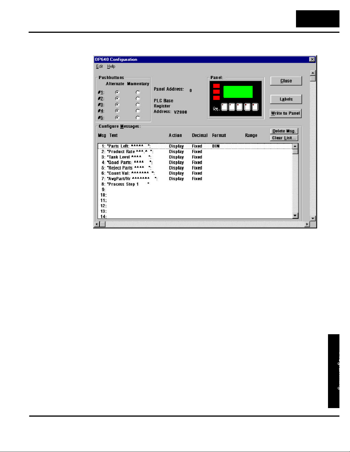
O
p
erato
r
P
ane
l
P
r
o
gra
m
m
i
n
g
5--15
Programming Examples
Displayin
g
Message
s
The following example uses the configuration shown below.
BIN
BIN
BIN
BIN
BIN
Display Fixed
BIN
BIN
Examples
Page 65
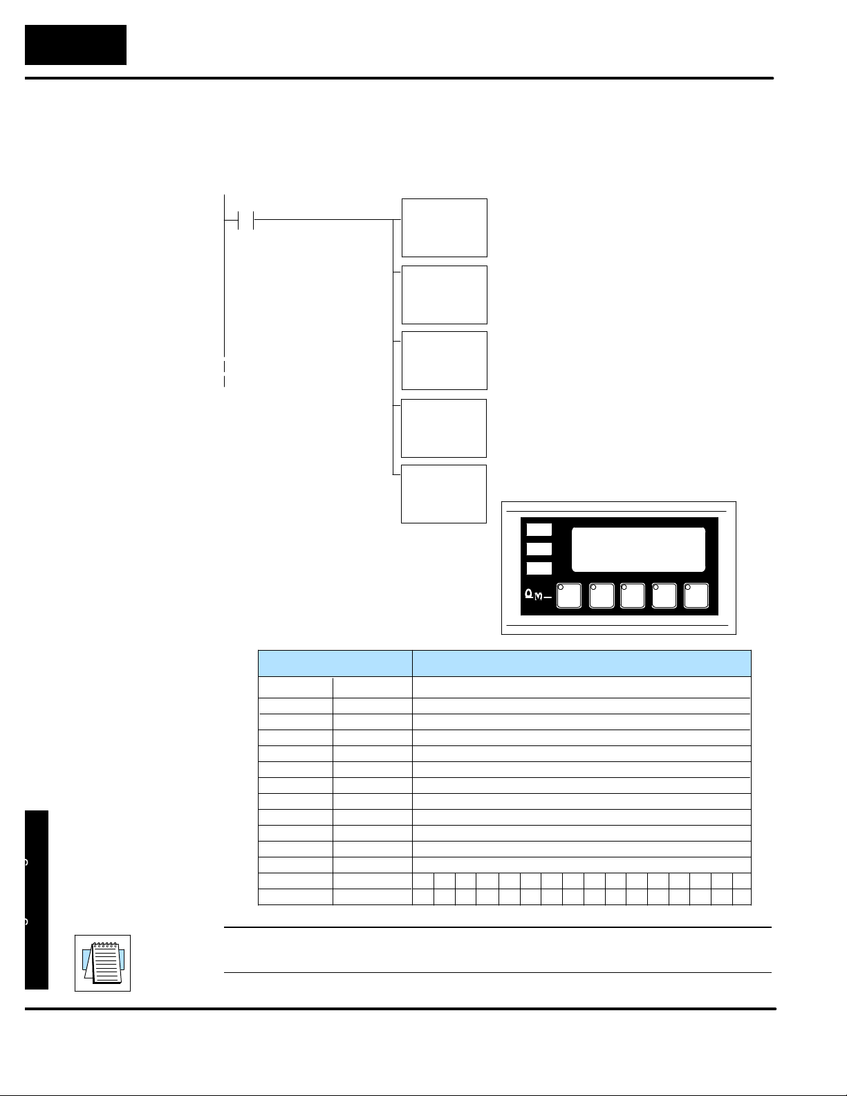
Y
ourPanelProgramming
5--16
Programming Examples
Displayin
g
Messages
Example
The second line is displaying BCD message #4. The data for the data field which is
displayed in the second line is from location N7:54. The bottom line is displaying text
message #8. The top and third lines use data display message #140, which has
been configured as a blank text message.
I:2
13
MOVE
Source
MOVE
Source
MOVE
Source
Dest
MOVE
Source
MOVE
Source
Dest
140
N7:0Dest
N7:1Dest
140
N7:2
N7:3Dest
N7:54
N7:6
Selects message #140 (blank) for the top
display line.
Selects message #4 for the second display line.
4
Puts message #140 (blank) on the third line.
Puts message #8 on the bottom line.
8
Copy data from N7:54 into the second line
data field.
Good Parts Left: 235
Process Step 1
Example Address
N7:0
N7:1
N7:2
N7:3
N7:4
N7:5
N7:6
N7:7
N78
N7:9
N7:10
N711
N7:12
N7:13
Examples
NOTE: While the OP--640 will display BCD Double and Floating Point numbers, it
M+0
M+1
M+2
M+3
M+4
M+5
M+6
M+7
M+8
M+9
M+10
M+11
M+12 Status
M+13 Control
Top line message selection
Second line message selection
Third line message selection
Bottom line message selection
Top line data
Not used with A--B (see Note)
Second line data
Not used with A--B (see Note)
Third line data
Bottom line data
Top line data
Function
Not used with A--B (see Note)
L1F
F2
L2
F1F3F5 F4
L1L3L2FL3FBD
does not support these functions when used with A--B PLCs.
Page 66
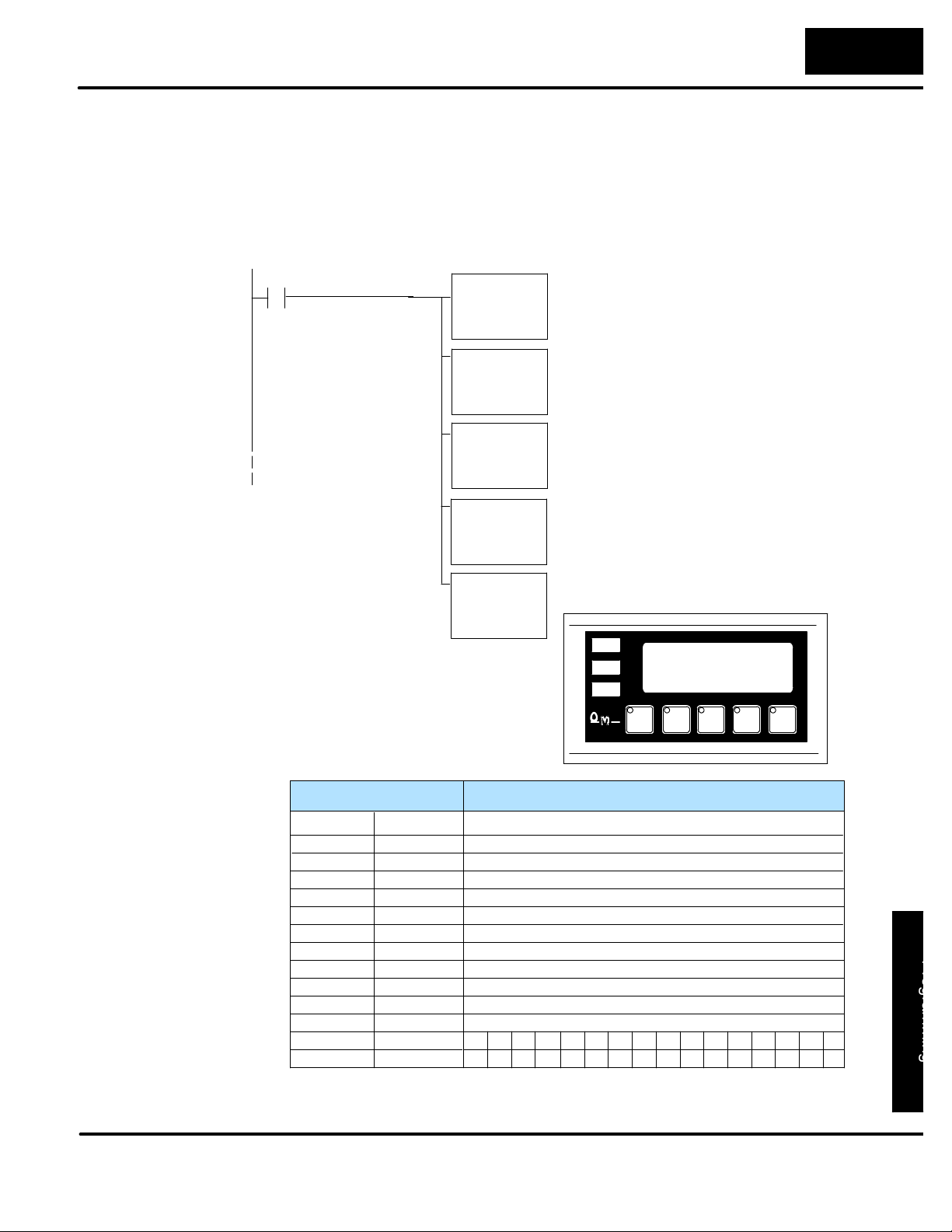
O
p
erato
r
P
ane
l
P
r
o
gra
m
m
i
n
g
5--17
Programming Examples
DisplayingBinar
y
Numbers
This example is similar to the previous example, except that it uses a binary number
in the top line display. The top line uses data display message #1, which has been
configured as a Binary display message. The data for the top line data field is a
constant number, 56432 (DC70 Hexadecimal). The third line is text message #8.
The second and bottom linesuse textmessage #140, which has been configured as
a blank text message.
I:2
14
MOVE
Source
MOVE
Source
MOVE
Source
Dest
MOVE
Source
MOVE
Source
Dest
N7:0Dest
140
N7:1Dest
N7:2
140
N7:3Dest
&HDC70
N7:4
Selects message #1 for the top display line.
1
Selects message #140 (blank) for the second
display line.
Puts message #8 on the third line.
8
Puts message #140 on the bottom line.
Moves constant 56432 into top line data field.
Good Parts Left: 56432
Process Step 1
Example Address
N7:0
N7:1
N7:2
N7:3
N7:4
N7:5
N7:6
N7:7
N78
N7:9
N7:10
N711
N7:12
N7:13
M+0
M+1
M+2
M+3
M+4
M+5
M+6
M+7
M+8
M+9
M+10
M+11
M+12 Status
M+13 Control
Function
Top line message selection
Second line message selection
Third line message selection
Bottom line message selection
Top line data
Not used with A--B (see Note)
Second line data
Not used with A--B (see Note)
Third line data
Bottom line data
Top line data
Not used with A--B (see Note)
F5 F4
L1F
F3
L3L2FL3FBD
F2
L2
Examples
F1
L1
Page 67

6
Troubleshooting
In This Chapter. . . .
— Troubleshooting
— Panel Configuration Problems
— Panel to PLC Communications
— A--B Panel to PLC Communications
Page 68
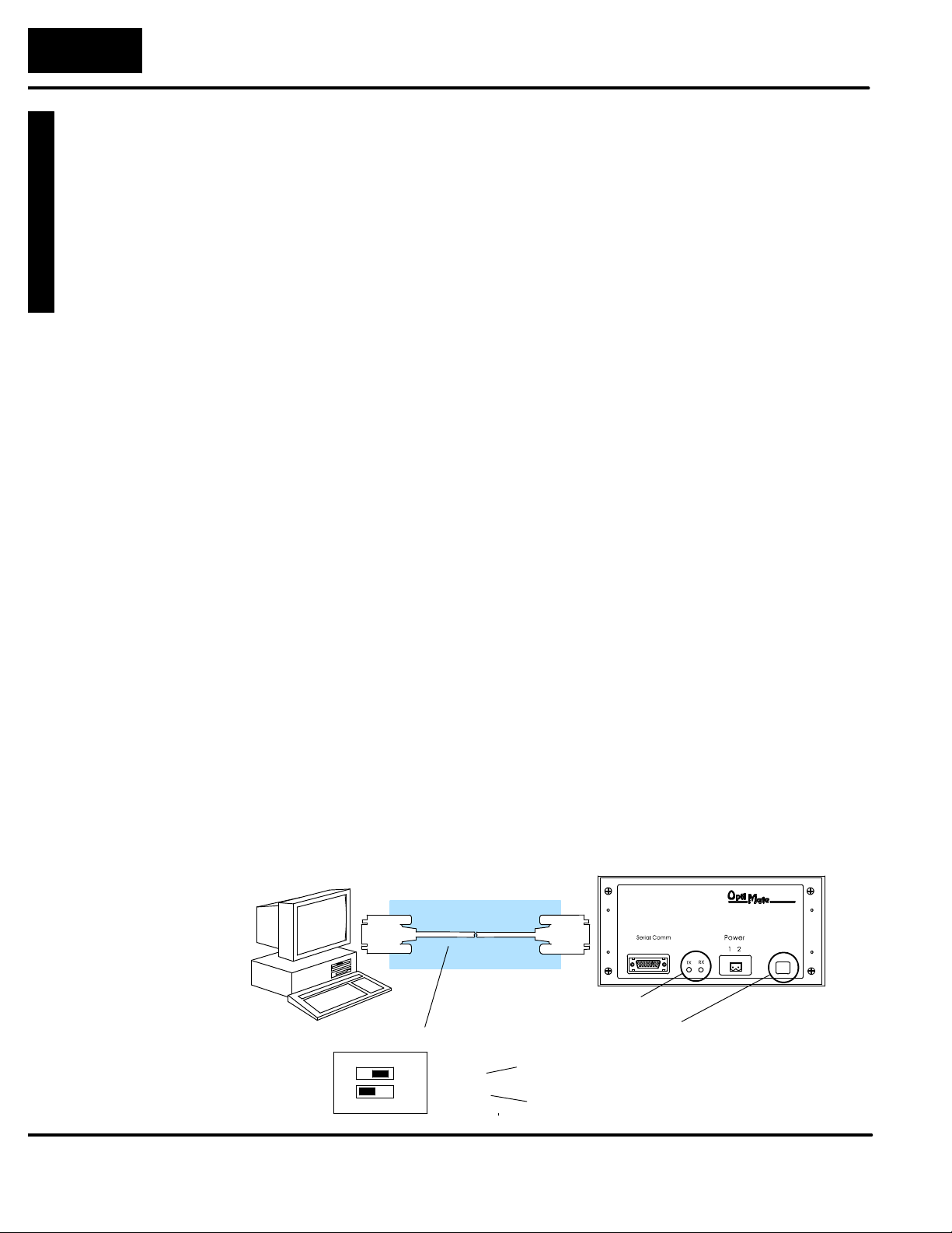
Y
ourPanelTroubleshooting
6--
2
Programming Examples
Troubleshooting the OP--640 Panel
Troubleshooting
Panel Configuration
Problems
In this section, we explain how to isolate potential problems which may occur while
using the OP-640. If you are unable to troubleshoot and correct your problem using
these procedures, please contact our technical product support team between the
hours of 9:00 AM and 6:00 PM (EST) Monday through Friday.
We have organized the troubleshooting section into two categories:
S Panel configuration problems
S Panel and PLC communications failures
We explained in previous sections that the OP--WINEDIT configuration software is
used to create OP-panel applications and to download and upload your OP-panel
programs. If you are online with the panel and communications fails, the following
error message is displayed:
“Could not communicate with panel” (OP--WINEDIT )
If this occurs, check the following in the order given:
1. Check the rear panel RX/TX LEDs while attempting the Upload or Download operation. Both LEDs should be giving slow alternating flash signals, indicating the PC and OP--panel are connected. If only the TX (transmitter) LED
is flashing, or if the TX/RX LEDs are not alternating between flashes, check
that the OP--panel is set to the configuration mode by setting the RUN/PGM
DIP switch to the PGM position.
2. Check to make sure the configuration cable (OP--ACBL--1) is properly
connected.
3. Make sure the correct communications port is selected with the software,
such as COM1, COM2, COM3, COM4.
4. Check the 24VDC power source and connections.
5. Make sure that DirectSOFT programming software is not running.
6. After checking the above items, repeat the online panel Download or
Upload procedure.
Rear Panel View
OP-ACBL-1
?
RX/TX LEDs
Check cable connections.
RUN
1
2
ON
PGM
TERM
RUN/PGM DIP Switch
Place the PGM/RUN switch in the PGM
position when configuring the panel.
TERM switch stays in the off position.
Page 69
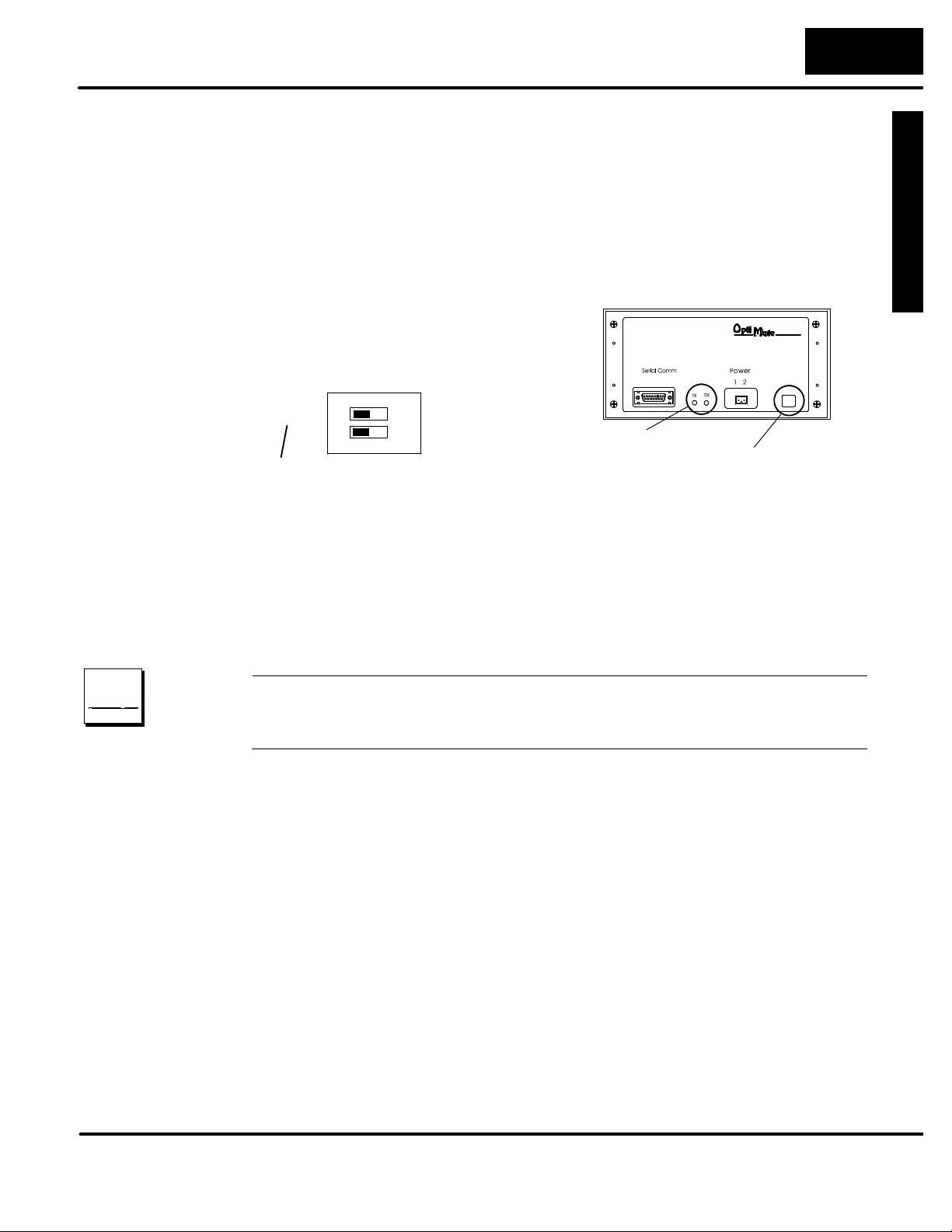
O
p
erato
r
P
ane
l
T
r
oubleshoo
t
i
n
g
6--
3
Programming Examples
Panel to PLC
Communications
Problems
If you experience communications difficulties between the OP-panel and PLC for a
period of twelve seconds, the LEDs in the corners of the five pushbuttons will flash
rapidly.
In this case, you should check the following items:
1. Observe the TX and RX LEDs on the rear of the panel. Both LEDs should be a
steady flash or glow (depending on baud rate). If not, check and make sure you
are using the proper communications cable and that it is securely connected.
2. Examine the PGM/RUN DIP switch to
Rear Panel View
make sure it is placed in the RUN position.
You must cycle OP-panel power for address switch changes to take effect.
ON
RUN
1
2
PGM
TERM
RX/TX LEDs
PGM/RUN DIP Switch
Place the PGM/RUN switch in the RUN
position when running the program.
3. Examine the communications information for the proper PLC type, protocol,
baud rate, parity, stop bit, address number. Use the user manual for the PLC
product you are using to determine the proper settings.
Direct
LOGIC
PLC
4. If you are using an OP cable, verify cable pinout. For RS--422 connec-
tions use a Belden 9729 or equivalent cable.
5. Check 24VDC power source and connections.
DirectLOGIC PLCs : If you are using the secondary communications port such as
DirectLOGIC PLC port 2, ensure the communications port address and protocol
setting match.
Page 70

Y
ourPanelTroubleshooting
6--
4
Programming Examples
Allen-Bradley
Panel to PLC
Communications
Problems
OTHER
PLC
For Allen-Bradley, you must connect to Channel 0 (bottom serial port), using DF1 in
full duplex mode. Typically, the onlychange that needs to be made to channel 0 is the
baud rate. Leave all other settings attheir default value. TheAllen-Bradley port must
be set to either 4800 or 9600 baud. No other baud rates are supported between the
OP-panel and Allen-Bradley PLC. Also, the base memory area must be expanded to
include the full range of registers such as N7:0 through N7:13.
OTHER PLCs : Regardless of which PLC brand you are implementing, the
communications parameters should be reviewed and properly configured. Please
check the appropriate manual for your PLC product to ensure proper
communications port and panel type settings.
Page 71

1
A
Appendix A
Worksheets
In This Appendix. . . .
— Example Application/Message Worksheet
— Blank Application/Message Worksheet
Page 72
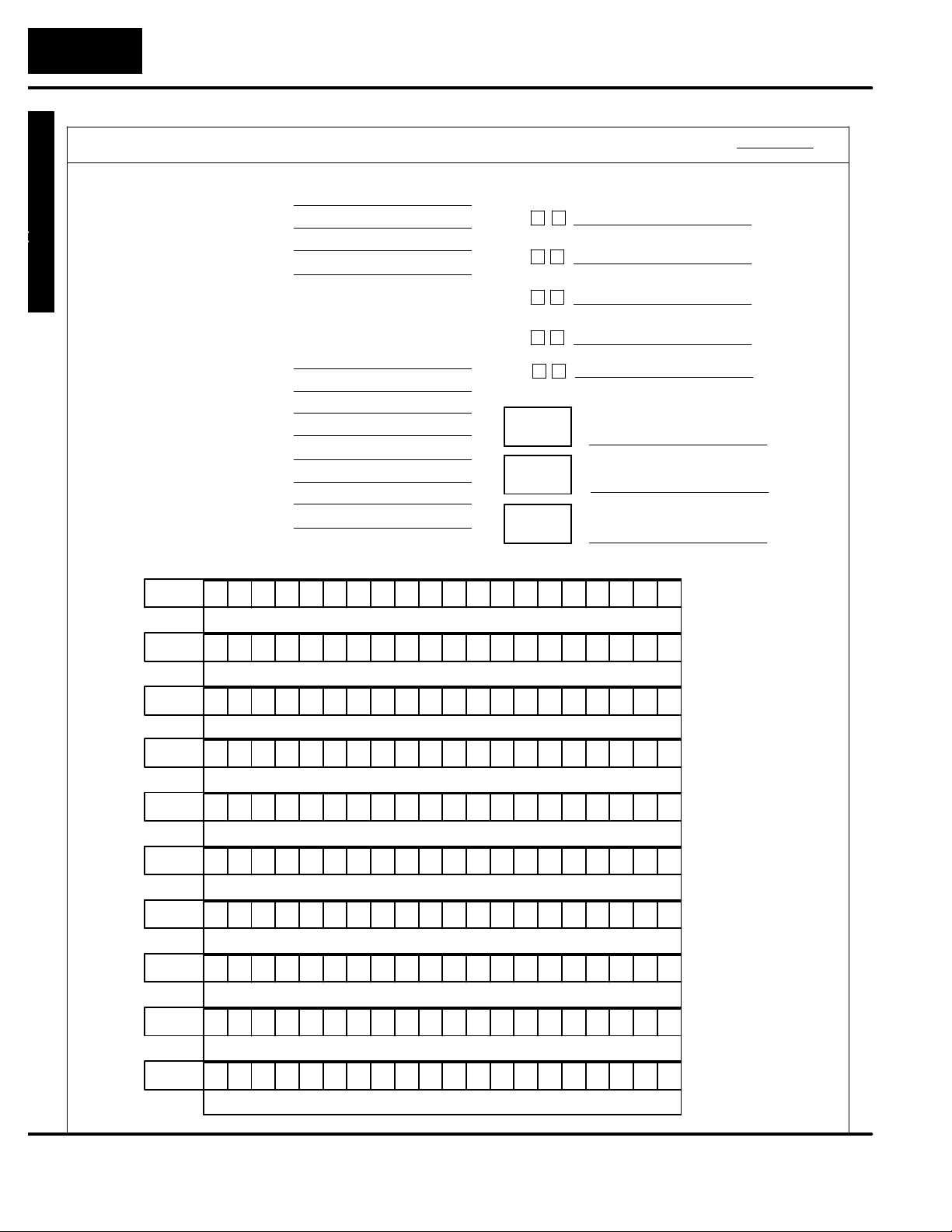
A--
2
Application Worksheet
DESCRIPTION
System Type
Panel Type
PLC Base Register Addr
PLC CONFIGURATION :
PLC Family
CPU Model
Protocol
PLC Address
PLC Timout
Baud Rate
Parity
Data/Stop Bits
MESSAGE:
Text
No.
1
P a r t s f t : ^ ^
No.
No.
No.
No.
No.
No.
No.
No.
Action:
2
Action: Range:
3
Action: Range:
4
Action: Range:
5
Action: Range:
6
Action: Range:
7
Action: Range:
8
Action: Range:
9
Display N/A
Text Message
P r o d u c t R e ^ ^ ^ . ^
Display
Text Message
T a n k levL
Display
Text Message
G o o d P :sa r
Display
Text Message
R e j e c t ta r s :P
Display
Text Message
C o u n t V a
Display
Text Message
A v g P rHt /r
Display
Text Message
r o c t p 1s Se eP
Display
Text Message
EXAMPLE WORKSHEET
OP--640 Demo
:
Single Panel
OP--640
V2000
DirectLOGIC
F1--130
K Sequence
1
3
9600
ODD
e
L
Data Format: Binary
Data Format: BCD
e : ^
Data Format: BCD
t ^ ^ ^ ^
Data Format: BCD
Data Format: BCD
l
Data Format: BCD Double
a
Data Format: BCD Double
s
F1
F2
F3
F4
F5
Lamp1
Yellow
Lamp2
Lamp3
^ ^
a t
^ ^ ^ ^ ^ ^ ^
:
^
:
PAGE:
PUSHBUTTONS / LAMPS :
A M
(Alternate/Momentary)
x
x
x
x
x
Red
Green
^
Range:
N/A
^ ^
^ ^ ^ ^ ^ ^ ^^
^
N/A
N/A
^ ^ ^ ^
N/A
^
N/A
N/A
N/A
No.
10
Action:
Text Message
Action:
Data Format:
Data Format:
Range:
Range:
Page 73
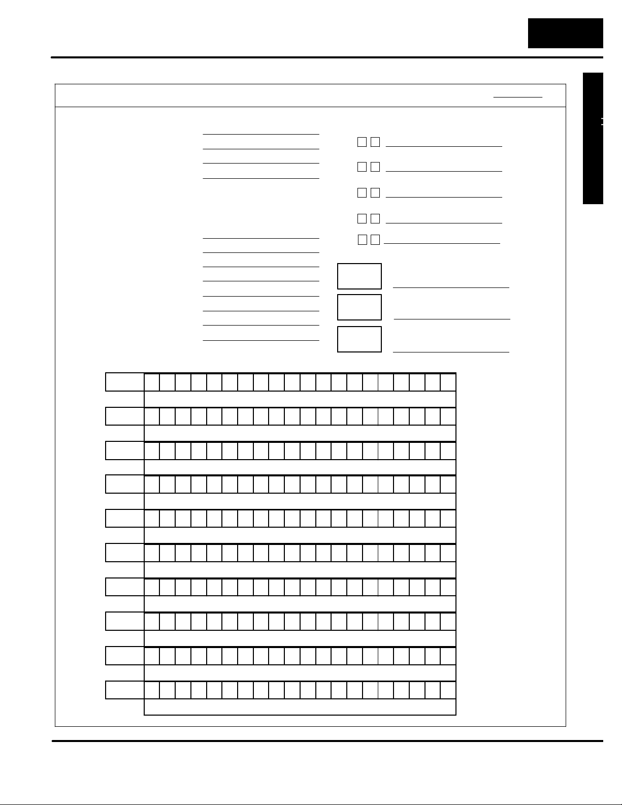
A
ppend
i
x
A
D
L20
5Memo
r
y
M
a
pAppend
i
x
A
A--
3
Application Worksheet
OP-640 APPLICATION WORKSHEET
DESCRIPTION
System Type
Panel Type
PLC Base Register Addr
PLC CONFIGURATION :
PLC Family
CPU Model
Protocol
PLC Address
PLC Timout
Baud Rate
Parity
Data/Stop Bits
MESSAGE:
Text Message
No.
Action:
No.
Action: Data Format: Range:
No.
Action: Data Format: Range:
No.
Action: Data Format: Range:
No.
Action: Data Format: Range:
No.
Action: Data Format: Range:
No.
Action: Data Format: Range:
No.
Action: Data Format: Range:
No.
Action: Data Format: Range:
No.
Action: Data Format: Range:
PAGE:
PUSHBUTTONS/LAMPS
:
A M
(Alternate/Momentary)
F1
F2
F3
F4
F5
Red
Lamp1
Yellow
Lamp2
Green
Lamp3
Data Format: Range:
Page 74
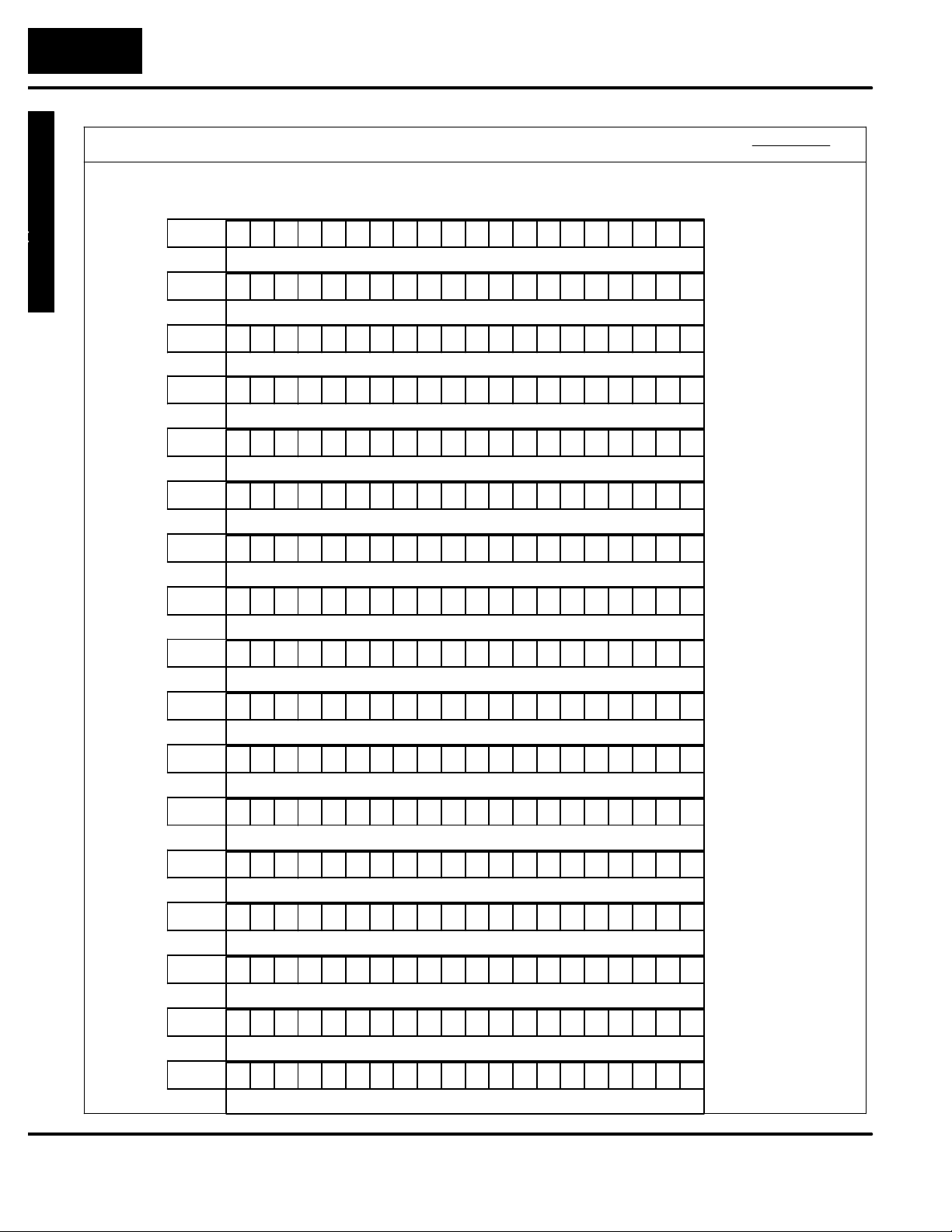
A--
4
Application Worksheet
OP-640 MESSAGE WORKSHEET
MESSAGE:
Text Message
No.
Action: Data Format: Range:
No.
Action: Data Format: Range:
No.
Action: Data Format: Range:
No.
Action: Data Format: Range:
No.
Action: Data Format: Range:
No.
PAGE:
PAGE:
No.
No.
No.
No.
No.
No.
No.
No.
No.
Action: Data Format: Range:
Action: Data Format: Range:
Action: Data Format: Range:
Action: Data Format: Range:
Action: Data Format: Range:
Action: Data Format: Range:
Action: Data Format: Range:
Action: Data Format: Range:
Action: Data Format: Range:
Action: Data Format: Range:
No.
Action: Data Format: Range:
No.
Action: Data Format: Range:
Page 75

1
Index
A
Application, planning, 1--4
B
Back-panel, layout, 1--5
C
Communications Cable, recommended, 2--5
Configuration
preparation, 4--2
software, 4--2
Configuration Cable, 2--3
Configuring
communications, 4--5
panel functions, 4--5
Connecting Cables, chart, 2--5
details, 2--6
GE Series, 2--5
pinouts, 2--6
Control Register, 3--4
D
Decimal point, placement, 3--9
Dynamic Messages, 3--5
F
Frequently Asked Questions, 1--6
K
Keypad, entry, 1--6
L
Label
creating, 2--7
installation, 2--9
Lamp
example, 5--6, 5--12, 5--13
flash example, 5--6, 5--12, 5--13
labels, 2--7
operation, 3--12
M
Mapping
control register, 3--16, 3--17
status register, 3--16, 3--17
Memory
register assignment, 3--14
register definition, 3--14
Memory Mapping, overview, 3--16
Message, display overview, 1--4
Message Display
operations, 3--5
types, 3--5
Page 76

ndex--2
O
S
OP--9001, cable connectors, 2--5
OP--9001 Communications Master, 2--4
OP--WINEDIT
configuration cable, 2--3
configuration software, 2--3, 4--2
installation, 4--3
system requirments, 4--3
user steps, 4--3
P
Panel
cutout dimensions, 2--10
mounting dimensions, 2--11
Panel Configuration, problems, 6--2
Power Receptacle, 2--2
Power Supply
connections, 2--2
connectors, 2--2
requirements, 2--2, 2--11
Pushbuttons
labels, 2--7
operation, 1--5
Serial Port, 1--5
Specifications, 2--11
communication link, 2--11
environmental, 2--11
NEMA rating, 2--11
power connector, 2--11
storage temperature, 2--11
Static Message
display, 3--5
operation, 3--5
Status and Control
bit definition, 3--4
bit-level access, 3--3
register overview, 3--3
Status Register, 3--4
T
Toubleshooting, 6--2 to 6--4
R
RS--422, communications, 2--4
 Loading...