

Page 1

DL06 Micro PLC User Manual
Volume 2 of 2
Manual Number: D0-06USER-M
Page 2

DL06 Micro PLC User Manual, 3rd Edition, Rev. C
Page 3

~ WARNING ~
Thank you for purchasing automation equipment from Automationdirect.com®, doing business as,
AutomationDirect. We want your new automation equipment to operate safely. Anyone who installs or
uses this equipment should read this publication (and any other relevant publications) before installing or
operating the equipment.
To minimize the risk of potential safety problems, you should follow all applicable local and national
codes that regulate the installation and operation of your equipment. These codes vary from area to area
and usually change with time. It is your responsibility to determine which codes should be followed, and
to verify that the equipment, installation, and operation is in compliance with the latest revision of these
codes.
At a minimum, you should follow all applicable sections of the National Fire Code, National Electrical
Code, and the codes of the National Electrical Manufacturer’s Association (NEMA). There may be local
regulatory or government offices that can also help determine which codes and standards are necessary for
safe installation and operation.
Equipment damage or serious injury to personnel can result from the failure to follow all applicable
codes and standards. We do not guarantee the products described in this publication are suitable for
your particular application, nor do we assume any responsibility for your product design, installation, or
operation.
Our products are not fault-tolerant and are not designed, manufactured or intended for use or resale as
on-line control equipment in hazardous environments requiring fail-safe performance, such as in the
operation of nuclear facilities, aircraft navigation or communication systems, air traffic control, direct life
support machines, or weapons systems, in which the failure of the product could lead directly to death,
personal injury, or severe physical or environmental damage (“High Risk Activities”). AutomationDirect
specifically disclaims any expressed or implied warranty of fitness for High Risk Activities.
For additional warranty and safety information, see the Terms and Conditions section of our catalog.
If you have any questions concerning the installation or operation of this equipment, or if you need
additional information, please call us at 770-844-4200.
This publication is based on information that was available at the time it was printed. At
AutomationDirect we constantly strive to improve our products and services, so we reserve the right to
make changes to the products and/or publications at any time without notice and without any obligation.
This publication may also discuss features that may not be available in certain revisions of the product.
Trademarks
This publication may contain references to products produced and/or offered by other companies. The
product and company names may be trademarked and are the sole property of their respective owners.
AutomationDirect disclaims any proprietary interest in the marks and names of others.
Copyright 2011, Automationdirect.com Incorporated
All Rights Reserved
No part of this manual shall be copied, reproduced, or transmitted in any way without the prior, written
consent of Automationdirect.com Incorporated. AutomationDirect retains the exclusive rights to all
information included in this document.
Page 4

~ AVERTISSEMENT ~
Nous vous remercions d’avoir acheté l’équipement d’automatisation de Automationdirect.comMC, en faisant des
affaires comme, AutomationDirect. Nous tenons à ce que votre nouvel équipement d’automatisation fonctionne en
toute sécurité. Toute personne qui installe ou utilise cet équipement doit lire la présente publication (et toutes les
autres publications pertinentes) avant de l’installer ou de l’utiliser.
Afin de réduire au minimum le risque d’éventuels problèmes de sécurité, vous devez respecter tous les codes locaux
et nationaux applicables régissant l’installation et le fonctionnement de votre équipement. Ces codes diffèrent d’une
région à l’autre et, habituellement, évoluent au fil du temps. Il vous incombe de déterminer les codes à respecter et
de vous assurer que l’équipement, l’installation et le fonctionnement sont conformes aux exigences de la version la
plus récente de ces codes.
Vous devez, à tout le moins, respecter toutes les sections applicables du Code national de prévention des incendies,
du Code national de l’électricité et des codes de la National Electrical Manufacturer’s Association (NEMA). Des
organismes de réglementation ou des services gouvernementaux locaux peuvent également vous aider à déterminer
les codes ainsi que les normes à respecter pour assurer une installation et un fonctionnement sûrs.
L’omission de respecter la totalité des codes et des normes applicables peut entraîner des dommages à l’équipement
ou causer de graves blessures au personnel. Nous ne garantissons pas que les produits décrits dans cette publication
conviennent à votre application particulière et nous n’assumons aucune responsabilité à l’égard de la conception, de
l’installation ou du fonctionnement de votre produit.
Nos produits ne sont pas insensibles aux défaillances et ne sont ni conçus ni fabriqués pour l’utilisation ou la revente
en tant qu’équipement de commande en ligne dans des environnements dangereux nécessitant une sécurité absolue,
par exemple, l’exploitation d’installations nucléaires, les systèmes de navigation aérienne ou de communication, le
contrôle de la circulation aérienne, les équipements de survie ou les systèmes d’armes, pour lesquels la défaillance du
produit peut provoquer la mort, des blessures corporelles ou de graves dommages matériels ou environnementaux
(«activités à risque élevé»). La société AutomationDirect nie toute garantie expresse ou implicite d’aptitude à
l’emploi en ce qui a trait aux activités à risque élevé.
Pour des renseignements additionnels touchant la garantie et la sécurité, veuillez consulter la section Modalités et
conditions de notre documentation. Si vous avez des questions au sujet de l’installation ou du fonctionnement de cet
équipement, ou encore si vous avez besoin de renseignements supplémentaires, n’hésitez pas à nous téléphoner au
770-844-4200.
Cette publication s’appuie sur l’information qui était disponible au moment de l’impression. À la société
AutomationDirect, nous nous efforçons constamment d’améliorer nos produits et services. C’est pourquoi nous
nous réservons le droit d’apporter des modifications aux produits ou aux publications en tout temps, sans préavis ni
quelque obligation que ce soit. La présente publication peut aussi porter sur des caractéristiques susceptibles de ne
pas être offertes dans certaines versions révisées du produit.
Marques de commerce
La présente publication peut contenir des références à des produits fabriqués ou offerts par d’autres entreprises. Les
désignations des produits et des entreprises peuvent être des marques de commerce et appartiennent exclusivement à
leurs propriétaires respectifs. AutomationDirect nie tout intérêt dans les autres marques et désignations.
Copyright 2011, Automationdirect.com Incorporated
Tous droits réservés
Nulle partie de ce manuel ne doit être copiée, reproduite ou transmise de quelque façon que ce soit sans le
consentement préalable écrit de la société Automationdirect.com Incorporated. AutomationDirect conserve les
droits exclusifs à l’égard de tous les renseignements contenus dans le présent document.
Page 5

Table of ConTenTs
Chapter 1: Getting Started
Introduction ............................................................................................................... 1–2
The Purpose of this Manual ...................................................................................... 1–2
Supplemental Manuals ............................................................................................. 1–2
Technical Support ....................................................................................................1–2
Conventions Used ......................................................................................................1–3
Key Topics for Each Chapter .....................................................................................1–3
DL06 Micro PLC Overview .........................................................................................1–4
The DL06 PLC Features ............................................................................................1–4
DirectSOFT Programming for Windows™ ................................................................1–4
Handheld Programmer ............................................................................................. 1–5
I/O Quick Selection Guide ......................................................................................... 1–5
Quick Start .................................................................................................................1–6
Steps to Designing a Successful System ................................................................. 1–10
Questions and Answers about DL06 Micro PLCs ....................................................1–12
Chapter 2: Installation, Wiring, and Specifications
Safety Guidelines ....................................................................................................... 2–2
Plan for Safety .......................................................................................................... 2–2
Three Levels of Protection ........................................................................................2–3
Emergency Stops ......................................................................................................2–3
Emergency Power Disconnect ..................................................................................2–4
Orderly System Shutdown ........................................................................................2–4
Class 1, Division 2 Approval .....................................................................................2–4
Orientation to DL06 Front Panel ..............................................................................2–5
Terminal Block Removal ...........................................................................................2–6
Mounting Guidelines ................................................................................................. 2–7
Page 6

DL06 Micro PLC User Manual, 3rd Edition, Rev. D
ii
Table of Contents
Unit Dimensions ....................................................................................................... 2–7
Enclosures ................................................................................................................2–7
Panel Layout & Clearances ....................................................................................... 2–8
Using Mounting Rails ...............................................................................................2–9
Environmental Specifications .................................................................................. 2–10
Agency Approvals ...................................................................................................2–10
Marine Use ............................................................................................................. 2–10
Wiring Guidelines .................................................................................................... 2–11
External Power Source ............................................................................................2–12
Planning the Wiring Routes .................................................................................... 2–12
Fuse Protection for Input and Output Circuits ........................................................ 2–13
I/O Point Numbering .............................................................................................2–13
System Wiring Strategies ........................................................................................2–14
PLC Isolation Boundaries ........................................................................................2–14
Connecting Operator Interface Devices .................................................................. 2–15
Connecting Programming Devices ......................................................................... 2–15
Sinking / Sourcing Concepts ..................................................................................2–16
I/O “Common” Terminal Concepts ........................................................................ 2–17
Connecting DC I/O to “Solid State” Field Devices .................................................. 2–18
Solid State Input Sensors ........................................................................................ 2–18
Solid State Output Loads ........................................................................................2–18
Relay Output Wiring Methods ................................................................................ 2–20
Relay Outputs-Transient Suppression For Inductive Loads in a Control System ....... 2–21
Prolonging Relay Contact Life ................................................................................2–26
DC Input Wiring Methods ...................................................................................... 2–27
DC Output Wiring Methods ................................................................................... 2–28
High-Speed I/O Wiring Methods ............................................................................ 2–29
Wiring Diagrams and Specifications ....................................................................... 2–30
D0–06AA I/O Wiring Diagram ................................................................................ 2–30
D0–06AR I/O Wiring Diagram ................................................................................ 2–32
D0–06DA I/O Wiring Diagram ...............................................................................2–34
D0–06DD1 I/O Wiring Diagram ............................................................................. 2–36
D0–06DD2 I/O Wiring Diagram ............................................................................. 2–38
D0–06DR I/O Wiring Diagram ................................................................................2–40
D0–06DD1–D I/O Wiring Diagram .........................................................................2–42
D0–06DD2–D I/O Wiring Diagram .........................................................................2–44
D0–06DR–D I/O Wiring Diagram ...........................................................................2–46
Page 7

DL06 Micro PLC User Manual, 3rd Edition, Rev. D
iii
Table of Contents
Glossary of Specification Terms .............................................................................. 2–48
Chapter 3: CPU Specifications and Operation
Overview 3–2
DL06 CPU Features ..................................................................................................3–2
CPU Specifications ..................................................................................................... 3–3
CPU Hardware Setup ................................................................................................. 3–4
Communication Port Pinout Diagrams .....................................................................3–4
Connecting the Programming Devices ..................................................................... 3–5
CPU Setup Information ............................................................................................3–5
Status Indicators ....................................................................................................... 3–6
Mode Switch Functions ............................................................................................ 3–6
Changing Modes in the DL06 PLC ........................................................................... 3–7
Mode of Operation at Power-up ..............................................................................3–7
Using Battery Backup ................................................................................................3–8
Battery Backup .........................................................................................................3–8
Auxiliary Functions ...................................................................................................3–9
Clearing an Existing Program ...................................................................................3–9
Initializing System Memory ......................................................................................3–9
Setting Retentive Memory Ranges .......................................................................... 3–10
Using a Password ...................................................................................................3–11
CPU Operation ......................................................................................................... 3–12
CPU Operating System ...........................................................................................3–12
Program Mode ....................................................................................................... 3–13
Run Mode ..............................................................................................................3–13
Read Inputs ............................................................................................................ 3–14
Service Peripherals and Force I/O ...........................................................................3–14
CPU Bus Communication .......................................................................................3–15
Update Clock, Special Relays and Special Registers .................................................3–15
Solve Application Program .....................................................................................3–16
Solve PID Loop Equations ....................................................................................... 3–16
Write Outputs ........................................................................................................3–16
Write Outputs to Specialty I/O ...............................................................................3–16
Diagnostics .............................................................................................................3–17
I/O Response Time ..................................................................................................3–17
Is Timing Important for Your Application? .............................................................. 3–17
Page 8

DL06 Micro PLC User Manual, 3rd Edition, Rev. D
iv
Table of Contents
Normal Minimum I/O Response ............................................................................. 3–18
Normal Maximum I/O Response ............................................................................3–18
Improving Response Time ......................................................................................3–19
CPU Scan Time Considerations ............................................................................... 3–20
Reading Inputs .......................................................................................................3–20
Writing Outputs .....................................................................................................3–20
Service Peripherals ..................................................................................................3–21
CPU Bus Communication .......................................................................................3–21
Update Clock/Calendar, Special Relays, Special Registers .......................................3–21
Application Program Execution ..............................................................................3–22
PLC Numbering Systems ........................................................................................ 3–23
PLC Resources ........................................................................................................3–23
V–Memory .............................................................................................................3–24
Binary-Coded Decimal Numbers ............................................................................3–24
Hexadecimal Numbers ...........................................................................................3–24
Memory Map ...........................................................................................................3–25
Octal Numbering System ....................................................................................... 3–25
Discrete and Word Locations ..................................................................................3–25
V-memory Locations for Discrete Memory Areas ....................................................3–25
Input Points (X Data Type) ..................................................................................... 3–26
Output Points (Y Data Type) ..................................................................................3–26
Control Relays (C Data Type) .................................................................................3–26
Timers and Timer Status Bits (T Data Type) ............................................................ 3–26
Timer Current Values (V Data Type) ....................................................................... 3–27
Counters and Counter Status Bits (CT Data type) ...................................................3–27
Counter Current Values (V Data Type) ...................................................................3–27
Word Memory (V Data Type) ................................................................................. 3–28
Stages (S Data type) ............................................................................................... 3–28
Special Relays (SP Data Type) ................................................................................. 3–28
DL06 System V-memory .......................................................................................... 3–29
System Parameters and Default Data Locations (V Data Type) ...............................3–29
DL06 Aliases ............................................................................................................. 3–31
DL06 Memory Map ..................................................................................................3–32
X Input/Y Output Bit Map ......................................................................................3–33
Stage Control/Status Bit Map ................................................................................. 3–34
Control Relay Bit Map .............................................................................................3–36
Page 9

DL06 Micro PLC User Manual, 3rd Edition, Rev. D
v
Table of Contents
Timer Status Bit Map ...............................................................................................3–38
Counter Status Bit Map ........................................................................................... 3–38
GX and GY I/O Bit Map ..........................................................................................3–39
Chapter 4: System Design and Configuration
DL06 System Design Strategies ................................................................................4–2
I/O System Configurations .......................................................................................4–2
Networking Configurations ......................................................................................4–2
Module Placement .....................................................................................................4–3
Slot Numbering........................................................................................................4–3
Automatic I/O Configuration .................................................................................... 4–4
Manual I/O Configuration ........................................................................................ 4–4
Power Budgeting ....................................................................................................... 4–5
Power supplied .......................................................................................................4–5
Power required by base unit ...................................................................................4–5
Power required by option cards ..............................................................................4–5
Configuring the DL06’s Comm Ports ........................................................................ 4–7
DL06 Port Specifications ...........................................................................................4–7
DL06 Port Pinouts ....................................................................................................4–7
Choosing a Network Specification ............................................................................ 4–8
RS-232 Network ....................................................................................................... 4–8
RS-422 Network ....................................................................................................... 4–8
RS-485 Network ....................................................................................................... 4–8
Connecting to MODBUS and DirectNET Networks .................................................. 4–9
MODBUS Port Configuration ....................................................................................4–9
DirectNET Port Configuration ................................................................................. 4–10
Non–Sequence Protocol (ASCII In/Out and PRINT) ............................................... 4–11
Non-Sequence Port Configuration ..........................................................................4–11
Network Slave Operation ........................................................................................ 4–12
MODBUS Function Codes Supported ..................................................................... 4–12
Determining the MODBUS Address ........................................................................ 4–12
If Your Host Software Requires the Data Type and Address ....................................4–13
Example 1: V2100 .................................................................................................. 4–14
Example 2: Y20 ......................................................................................................4–14
Example 3: T10 Current Value ................................................................................4–14
Page 10

DL06 Micro PLC User Manual, 3rd Edition, Rev. D
vi
Table of Contents
Example 4: C54 ......................................................................................................4–14
If Your MODBUS Host Software Requires an Address ONLY ...................................4–15
Example 1: V2100 584/984 Mode .........................................................................4–16
Example 2: Y20 584/984 Mode .............................................................................4–16
Example 3: T10 Current Value 484 Mode ..............................................................4–17
Example 4: C54 584/984 Mode ............................................................................. 4–17
Network Master Operation ..................................................................................... 4–17
Step 1: Identify Master Port # and Slave #..............................................................4–18
Step 2: Load Number of Bytes to Transfer .............................................................. 4–18
Step 3: Specify Master Memory Area ......................................................................4–19
Step 4: Specify Slave Memory Area ........................................................................4–20
Communications from a Ladder Program ...............................................................4–21
Multiple Read and Write Interlocks ......................................................................... 4–21
Network Master Operation (using MRX and MWX Instructions) .........................4–22
MODBUS Function Codes Supported ..................................................................... 4–22
MODBUS Read from Network(MRX) ......................................................................4–23
MRX Slave Memory Address ...................................................................................4–24
MRX Master Memory Addresses ............................................................................. 4–24
MRX Number of Elements ...................................................................................... 4–24
MRX Exception Response Buffer .............................................................................4–24
MODBUS Write to Network (MWX) .......................................................................4–25
MWX Slave Memory Address .................................................................................4–26
MWX Master Memory Addresses ............................................................................4–26
MWX Number of Elements .....................................................................................4–26
MWX Exception Response Buffer ............................................................................ 4–26
MRX/MWX Example in DirectSOFT ........................................................................ 4–27
Multiple Read and Write Interlocks ......................................................................... 4–27
Chapter 5: Standard RLL Instructions
Introduction ............................................................................................................... 5–2
Using Boolean Instructions .......................................................................................5–5
END Statement ........................................................................................................5–5
Simple Rungs ...........................................................................................................5–5
Normally Closed Contact .........................................................................................5–6
Contacts in Series ..................................................................................................... 5–6
Midline Outputs ....................................................................................................... 5–6
Page 11

DL06 Micro PLC User Manual, 3rd Edition, Rev. D
vii
Table of Contents
Parallel Elements .......................................................................................................5–7
Joining Series Branches in Parallel ............................................................................. 5–7
Joining Parallel Branches in Series ............................................................................. 5–7
Combination Networks ............................................................................................5–7
Comparative Boolean ............................................................................................... 5–8
Boolean Stack ...........................................................................................................5–8
Immediate Boolean ..................................................................................................5–9
Boolean Instructions ...............................................................................................5–10
Comparative Boolean .............................................................................................. 5–26
Immediate Instructions ...........................................................................................5–32
Timer, Counter and Shift Register Instructions ...................................................... 5–39
Using Timers ..........................................................................................................5–39
Timer Example Using Discrete Status Bits ............................................................... 5–41
Timer Example Using Comparative Contacts .......................................................... 5–41
Accumulating Timer Example using Discrete Status Bits ......................................... 5–43
Accumulator Timer Example Using Comparative Contacts .....................................5–43
Using Counters.......................................................................................................5–44
Counter Example Using Discrete Status Bits ...........................................................5–46
Counter Example Using Comparative Contacts ......................................................5–46
Stage Counter Example Using Discrete Status Bits ..................................................5–48
Stage Counter Example Using Comparative Contacts ............................................5–48
Up / Down Counter Example Using Discrete Status Bits ......................................... 5–50
Up / Down Counter Example Using Comparative Contacts ....................................5–50
Accumulator/Stack Load and Output Data Instructions ........................................5–52
Using the Accumulator ........................................................................................... 5–52
Copying Data to the Accumulator ..........................................................................5–52
Changing the Accumulator Data ............................................................................ 5–53
Using the Accumulator Stack ..................................................................................5–54
Using Pointers ........................................................................................................5–55
Logical Instructions (Accumulator) ......................................................................... 5–69
Math Instructions ....................................................................................................5–86
Transcendental Functions......................................................................................5–118
Bit Operation Instructions ..................................................................................... 5–120
Number Conversion Instructions (Accumulator) ..................................................5–127
Shuffle Digits Block Diagram ................................................................................5–139
Page 12

DL06 Micro PLC User Manual, 3rd Edition, Rev. D
viii
Table of Contents
Table Instructions ..................................................................................................5–141
Copy Data From a Data Label Area to V-memory ................................................. 5–143
Clock/Calendar Instructions .................................................................................. 5–171
CPU Control Instructions .......................................................................................5–173
Program Control Instructions ...............................................................................5–175
Interrupt Instructions ............................................................................................5–183
Message Instructions ............................................................................................. 5–186
Move Block Instruction (MOVBLK) .......................................................................5–189
Copy Data From a Data Label Area to V-memory ................................................. 5–189
Intelligent I/O Instructions ....................................................................................5–194
Read from Intelligent Module (RD) .......................................................................5–194
Write to Intelligent Module (WT) .........................................................................5–195
Network Instructions ............................................................................................. 5–196
Direct Text Entry ..................................................................................................5–200
Embedding date and/or time variables .................................................................5–201
Embedding V-memory data .................................................................................5–201
Data Format Suffixes for Embedded V-memory Data............................................5–202
Text Entry from V-memory ................................................................................... 5–203
MODBUS RTU Instructions ................................................................................... 5–204
MRX Slave Address Ranges ................................................................................... 5–205
MWX Slave Address Ranges..................................................................................5–208
MWX Master Memory Address Ranges .................................................................5–208
MWX Number of Elements ................................................................................5–208
MWX Exception Response Buffer .......................................................................... 5–208
ASCII Instructions ..................................................................................................5–210
Reading ASCII Input Strings ..................................................................................5–210
Writing ASCII Output Strings ................................................................................5–210
Managing the ASCII Strings .................................................................................5–211
Intelligent Box (IBox) Instructions ........................................................................ 5–230
Chapter 6: Drum Instruction Programming
Introduction ............................................................................................................... 6–2
Page 13

DL06 Micro PLC User Manual, 3rd Edition, Rev. D
ix
Table of Contents
Purpose .................................................................................................................... 6–2
Drum Terminology ................................................................................................... 6–2
Drum Chart Representation ......................................................................................6–3
Output Sequences ....................................................................................................6–3
Step Transitions ......................................................................................................... 6–4
Drum Instruction Types ............................................................................................ 6–4
Timer-Only Transitions .............................................................................................6–4
Timer and Event Transitions .....................................................................................6–5
Event-Only Transitions ..............................................................................................6–6
Counter Assignments ...............................................................................................6–6
Last Step Completion ............................................................................................... 6–7
Overview of Drum Operation ...................................................................................6–8
Drum Instruction Block Diagram ..............................................................................6–8
Powerup State of Drum Registers .............................................................................6–9
Drum Control Techniques ....................................................................................... 6–10
Drum Control Inputs .............................................................................................. 6–10
Self-Resetting Drum................................................................................................6–11
Initializing Drum Outputs ....................................................................................... 6–11
Using Complex Event Step Transitions ...................................................................6–11
Drum Instruction .....................................................................................................6–12
Timed Drum with Discrete Outputs (DRUM) .......................................................... 6–12
Event Drum (EDRUM) ............................................................................................6–14
Handheld Programmer Drum Mnemonics ..............................................................6–16
Masked Event Drum with Discrete Outputs (MDRMD) ........................................... 6–19
Masked Event Drum with Word Output (MDRMW) ...............................................6–21
Volume Two:
Table of ConTenTs
Page 14

DL06 Micro PLC User Manual, 3rd Edition, Rev. D
x
Table of Contents
Chapter 7: RLL
PLUS
Stage Programming
Introduction to Stage Programming ........................................................................7–2
Overcoming “Stage Fright” ...................................................................................... 7–2
Learning to Draw State Transition Diagrams ........................................................... 7–3
Introduction to Process States ..................................................................................7–3
The Need for State Diagrams ...................................................................................7–3
A 2–State Process .....................................................................................................7–3
RLL Equivalent .......................................................................................................... 7–4
Stage Equivalent .......................................................................................................7–4
Let’s Compare .......................................................................................................... 7–5
Initial Stages ............................................................................................................. 7–5
What Stage Bits Do ..................................................................................................7–6
Stage Instruction Characteristics ............................................................................... 7–6
Using the Stage Jump Instruction for State Transitions ..........................................7–7
Stage Jump, Set, and Reset Instructions ....................................................................7–7
Stage Program Example: Toggle On/Off Lamp Controller ...................................... 7–8
A 4–State Process .....................................................................................................7–8
Four Steps to Writing a Stage Program ...................................................................7–9
1. Write a Word Description of the application. .......................................................7–9
2. Draw the Block Diagram. .....................................................................................7–9
3. Draw the State Transition Diagram. .....................................................................7–9
4. Write the Stage Program. ..................................................................................... 7–9
Stage Program Example: A Garage Door Opener .................................................. 7–10
Garage Door Opener Example ...............................................................................7–10
Draw the Block Diagram ........................................................................................7–10
Draw the State Diagram .........................................................................................7–11
Add Safety Light Feature ........................................................................................7–12
Modify the Block Diagram and State Diagram .......................................................7–12
Using a Timer Inside a Stage ..................................................................................7–13
Add Emergency Stop Feature .................................................................................7–14
Exclusive Transitions ............................................................................................... 7–14
Stage Program Design Considerations ................................................................... 7–15
Stage Program Organization ..................................................................................7–15
How Instructions Work Inside Stages ...................................................................... 7–16
Using a Stage as a Supervisory Process ................................................................... 7–17
Page 15

DL06 Micro PLC User Manual, 3rd Edition, Rev. D
xi
Table of Contents
Stage Counter ........................................................................................................ 7–17
Power Flow Transition Technique ........................................................................... 7–18
Stage View in DirectSOFT .......................................................................................7–18
Parallel Processing Concepts ...................................................................................7–19
Parallel Processes .................................................................................................... 7–19
Converging Processes .............................................................................................7–19
Convergence Stages (CV) ....................................................................................... 7–19
Convergence Jump (CVJMP) ...................................................................................7–20
Convergence Stage Guidelines ............................................................................... 7–20
RLL
PLUS
(Stage) Instructions ....................................................................................7–21
Stage (SG) .............................................................................................................. 7–21
Initial Stage (ISG) ...................................................................................................7–22
Jump (JMP).............................................................................................................7–22
Not Jump (NJMP) ................................................................................................... 7–22
Converge Stage (CV) and Converge Jump (CVJMP) ...............................................7–23
Block Call (BCALL) .................................................................................................. 7–25
Block (BLK) ............................................................................................................. 7–25
Block End (BEND) ...................................................................................................7–25
Questions and Answers about Stage Programming ..............................................7–27
Chapter 8: PID Loop Operation
DL06 PID Control .......................................................................................................8–2
DL06 PID Control Features ....................................................................................... 8–2
Introduction to PID Control ...................................................................................... 8–4
What is PID Control? ................................................................................................ 8–4
Introducing DL06 PID Control ..................................................................................8–6
Process Control Definitions .......................................................................................8–8
PID Loop Operation ...................................................................................................8–9
Position Form of the PID Equation ............................................................................8–9
Reset Windup Protection ........................................................................................ 8–10
Freeze Bias .............................................................................................................8–11
Adjusting the Bias ...................................................................................................8–11
Step Bias Proportional to Step Change in SP ..........................................................8–12
Eliminating Proportional, Integral or Derivative Action ...........................................8–12
Velocity Form of the PID Equation ..........................................................................8–12
Page 16

DL06 Micro PLC User Manual, 3rd Edition, Rev. D
xii
Table of Contents
Bumpless Transfer ..................................................................................................8–13
Loop Alarms ........................................................................................................... 8–13
Loop Operating Modes ..........................................................................................8–14
Special Loop Calculations ....................................................................................... 8–14
Ten Steps to Successful Process Control.................................................................8–16
PID Loop Setup ........................................................................................................ 8–18
Some Things to Do and Know Before Starting .......................................................8–18
PID Error Flags ........................................................................................................8–18
Establishing the Loop Table Size and Location .......................................................8–18
Loop Table Word Definitions .................................................................................. 8–20
PID Mode Setting 1 Bit Descriptions (Addr + 00) ...................................................8–21
PID Mode Setting 2 Bit Descriptions (Addr + 01) ...................................................8–22
Mode/Alarm Monitoring Word (Addr + 06) ...........................................................8–23
Ramp/Soak Table Flags (Addr + 33) .......................................................................8–23
Ramp/Soak Table Location (Addr + 34) .................................................................. 8–24
Ramp/Soak Table Programming Error Flags (Addr + 35).........................................8–24
Configure the PID Loop..........................................................................................8–25
PID Loop Tuning ......................................................................................................8–40
Open-Loop Test .....................................................................................................8–40
Manual Tuning Procedure ...................................................................................... 8–41
Alternative Manual Tuning Procedures by Others ................................................... 8–44
Tuning PID Controllers ........................................................................................... 8–44
Auto Tuning Procedure ..........................................................................................8–45
Use DirectSOFT 5 Data View with PID View ...........................................................8–49
Open a New Data View Window ............................................................................8–49
Open PID View .......................................................................................................8–50
Using the Special PID Features ...............................................................................8–53
How to Change Loop Modes .................................................................................8–53
Operator Panel Control of PID Modes .................................................................... 8–54
PLC Modes Effect on Loop Modes .......................................................................... 8–54
Loop Mode Override .............................................................................................. 8–54
PV Analog Filter ...................................................................................................... 8–55
Creating an Analog Filter in Ladder Logic ...............................................................8–56
Use the DirectSOFT Filter Intelligent Box Instructions ............................................. 8-57
FilterB Example ....................................................................................................... 8-57
Ramp/Soak Generator ............................................................................................. 8–58
Page 17

DL06 Micro PLC User Manual, 3rd Edition, Rev. D
xiii
Table of Contents
Introduction ........................................................................................................... 8–58
Ramp/Soak Table ...................................................................................................8–59
Ramp/Soak Table Flags ...........................................................................................8–61
Ramp/Soak Generator Enable ................................................................................. 8–61
Ramp/Soak Controls ...............................................................................................8–61
Ramp/Soak Profile Monitoring ................................................................................8–62
Ramp/Soak Programming Errors .............................................................................8–62
Testing Your Ramp/Soak Profile ..............................................................................8–62
DirectSOFT Ramp/Soak Example ............................................................................. 8-63
Setup the Profile in PID Setup ................................................................................ 8-63
Program the Ramp/Soak Control in Relay Ladder ................................................... 8-63
Test the Profile ....................................................................................................... 8-64
Cascade Control .......................................................................................................8–65
Introduction ........................................................................................................... 8–65
Cascaded Loops in the DL06 CPU .......................................................................... 8–66
Tuning Cascaded Loops .........................................................................................8–67
Time-Proportioning Control ....................................................................................8–68
On/Off Control Program Example .......................................................................... 8–69
Feedforward Control ...............................................................................................8–70
Feedforward Example ............................................................................................. 8–71
PID Example Program .............................................................................................8–72
Program Setup for the PID Loop ............................................................................8–72
Troubleshooting Tips...............................................................................................8–75
Glossary of PID Loop Terminology .........................................................................8–77
Bibliography ........................................................................................................... 8–79
Chapter 9: Maintenance and Troubleshooting
Hardware System Maintenance ................................................................................9–2
Standard Maintenance .............................................................................................9–2
Diagnostics .................................................................................................................9–2
Diagnostics ...............................................................................................................9–2
Fatal Errors ...............................................................................................................9–2
Non-fatal Errors ........................................................................................................ 9–2
V-memory Error Code Locations ...............................................................................9–3
Special Relays (SP) Corresponding to Error Codes ....................................................9–3
Page 18

DL06 Micro PLC User Manual, 3rd Edition, Rev. D
xiv
Table of Contents
DL06 Micro PLC Error Codes .................................................................................... 9–4
Program Error Codes ................................................................................................ 9–5
CPU Indicators ...........................................................................................................9–6
PWR Indicator ..........................................................................................................9–6
RUN Indicator ..........................................................................................................9–7
CPU Indicator ........................................................................................................... 9–7
Communications Problems .......................................................................................9–7
I/O Point Troubleshooting ........................................................................................ 9–8
Possible Causes ........................................................................................................9–8
Some Quick Steps ....................................................................................................9–8
Handheld Programmer Keystrokes Used to Test an Output Point ............................. 9–9
Noise Troubleshooting ............................................................................................ 9–10
Electrical Noise Problems ........................................................................................9–10
Reducing Electrical Noise........................................................................................9–10
Machine Startup and Program Troubleshooting ...................................................9–11
Syntax Check .........................................................................................................9–11
Special Instructions .................................................................................................9–12
Duplicate Reference Check ..................................................................................... 9–13
Run Time Edits .......................................................................................................9–14
Run Time Edit Example ..........................................................................................9–15
Forcing I/O Points ..................................................................................................9–16
Regular Forcing with Direct Access ......................................................................... 9–18
Bit Override Forcing ...............................................................................................9–19
Bit Override Indicators ............................................................................................9–19
Reset the PLC to Factory Defaults ........................................................................... 9–20
Chapter 10: LCD Display Panel
Introduction to the DL06 LCD Display Panel .........................................................10–2
Keypad .. 10–2
Snap-in installation .................................................................................................. 10–3
Display Priority ........................................................................................................10–4
Menu Navigation ..................................................................................................... 10–5
Confirm PLC Type, Firmware Revision Level, Memory Usage, Etc. .......................10–6
Examining Option Slot Contents ............................................................................10–8
Page 19

DL06 Micro PLC User Manual, 3rd Edition, Rev. D
xv
Table of Contents
Menu 2, M2:SYSTEM CFG. ....................................................................................10–8
Monitoring and Changing Data Values ................................................................ 10–10
Menu 3, M3:MONITOR ......................................................................................10–10
Data Monitor .......................................................................................................10–10
V-memory values ..................................................................................................10–10
Pointer values ....................................................................................................... 10–12
Bit Monitor ............................................................................................................10–13
Bit status ..............................................................................................................10–13
Changing Date and Time ...................................................................................... 10–14
Menu 4, M4 : CALENDAR R/W .............................................................................10–14
Setting Password and Locking .............................................................................. 10–17
Menu 5, M5 : PASSWORD R/W ............................................................................ 10–17
Reviewing Error History .........................................................................................10–20
Menu 6, M6 : ERR HISTORY .................................................................................10–20
Toggle Light and Beeper, Test Keys .....................................................................10–21
Menu 7, M7 : LCD TEST&SET ..............................................................................10–21
PLC Memory Information for the LCD Display Panel ..........................................10–22
Data Format Suffixes for Embedded V-memory Data............................................10–22
Reserved memory registers for the LCD Display Panel .......................................... 10–23
V7742 bit definitions ............................................................................................ 10–24
Changing the Default Screen ................................................................................ 10–25
Example program for setting the default screen message .....................................10–25
DL06 LCD Display Panel Instruction (LCD) ...........................................................10–26
Source of message ...............................................................................................10–26
ASCII Character Codes .........................................................................................10–27
Example program: alarm with embedded date/time stamp .................................10–28
Example program: alarm with embedded V-memory data ...................................10–29
Example program: alarm text from V-memory with embedded V-memory data ..10–30
Appendix A: Auxiliary Functions
Introduction ...............................................................................................................A–2
Purpose of Auxiliary Functions .................................................................................. A–2
Accessing AUX Functions via DirectSOFT .................................................................. A–3
Accessing AUX Functions via the Handheld Programmer ..........................................A–3
Page 20

DL06 Micro PLC User Manual, 3rd Edition, Rev. D
xvi
Table of Contents
AUX 2* — RLL Operations .........................................................................................A–4
AUX 21 Check Program ...........................................................................................A–4
AUX 22 Change Reference .......................................................................................A–4
AUX 23 Clear Ladder Range .....................................................................................A–4
AUX 24 Clear Ladders ..............................................................................................A–4
AUX 3* — V-memory Operations ..............................................................................A–4
AUX 31 Clear V-memory ..........................................................................................A–4
AUX 4* — I/O Configuration .....................................................................................A–5
AUX 41 Show I/O Configuration ..............................................................................A–5
AUX 5* — CPU Configuration ...................................................................................A–5
AUX 51 Modify Program Name ................................................................................ A–5
AUX 53 Display Scan Time .......................................................................................A–5
AUX 54 Initialize Scratchpad ....................................................................................A–5
AUX 55 Set Watchdog Timer ...................................................................................A–5
AUX 56 CPU Network Address .................................................................................A–6
AUX 57 Set Retentive Ranges ...................................................................................A–6
AUX 58 Test Operations ........................................................................................... A–6
AUX 59 Bit Override ................................................................................................. A–7
AUX 5B Counter Interface Configuration .................................................................. A–7
AUX 5D Select PLC Scan Mode ................................................................................A–7
AUX 6* — Handheld Programmer Configuration ....................................................A–8
AUX 61 Show Revision Numbers .............................................................................. A–8
AUX 62 Beeper On/Off .............................................................................................A–8
AUX 65 Run Self Diagnostics ....................................................................................A–8
AUX 7* — EEPROM Operations .................................................................................A–8
Transferrable Memory Areas ..................................................................................... A–8
AUX 71 CPU to HPP EEPROM ................................................................................... A–8
AUX 72 HPP EEPROM to CPU ................................................................................... A–9
AUX 73 Compare HPP EEPROM to CPU ...................................................................A–9
AUX 74 HPP EEPROM Blank Check ........................................................................... A–9
AUX 75 Erase HPP EEPROM ...................................................................................... A–9
AUX 76 Show EEPROM Type .................................................................................... A–9
AUX 8* — Password Operations ...............................................................................A–9
AUX 81 Modify Password .........................................................................................A–9
AUX 82 Unlock CPU ............................................................................................... A–10
AUX 83 Lock CPU...................................................................................................A–10
Page 21

DL06 Micro PLC User Manual, 3rd Edition, Rev. D
xvii
Table of Contents
Appenedix B: DL06 Error codes
DL06 Error Codes ....................................................................................................... B–2
Appendix C: Instruction Execution Times
Introduction ...............................................................................................................C–2
V-Memory Data Registers .........................................................................................C–2
V-Memory Bit Registers ............................................................................................C–2
How to Read the Tables ...........................................................................................C–2
Instruction Execution Times ......................................................................................C–3
Boolean Instructions .................................................................................................C–3
Comparative Boolean Instructions ............................................................................C–4
Immediate Instructions ...........................................................................................C–11
Bit of Word Boolean Instructions ............................................................................C–12
Timer, Counter and Shift Register...........................................................................C–13
Accumulator Data Instructions ...............................................................................C–14
Logical Instructions.................................................................................................C–15
Math Instructions ...................................................................................................C–16
Differential Instructions ..........................................................................................C–19
Bit Instructions .......................................................................................................C–19
Number Conversion Instructions ............................................................................C–20
Table Instructions ...................................................................................................C–20
CPU Control Instructions ........................................................................................C–22
Program Control Instructions .................................................................................C–22
Interrupt Instructions ..............................................................................................C–22
Network Instructions ..............................................................................................C–22
Intelligent I/O Instructions ......................................................................................C–23
Message Instructions ..............................................................................................C–23
RLL
PLUS
Instructions .................................................................................................C–23
Drum Instructions ..................................................................................................C–23
Clock/Calendar Instructions ....................................................................................C–24
MODBUS Instructions .............................................................................................C–24
ASCII Instructions ...................................................................................................C–24
Appendix D: Special Relays
DL06 PLC Special Relays ........................................................................................... D–2
Startup and Real-Time Relays .................................................................................. D–2
Page 22

DL06 Micro PLC User Manual, 3rd Edition, Rev. D
xviii
Table of Contents
CPU Status Relays .................................................................................................... D–2
System Monitoring .................................................................................................. D–3
Accumulator Status ................................................................................................. D–3
HSIO Input Status .................................................................................................... D–4
HSIO Pulse Output Relay ......................................................................................... D–4
Communication Monitoring Relay ........................................................................... D–4
Option Slot Communication Monitoring Relay ........................................................ D–4
Option Slot Special Relay ........................................................................................ D–4
Counter 1 Mode 10 Equal Relays ............................................................................ D–5
Counter 2 Mode 10 Equal Relays ............................................................................ D–6
Appendix E: High-speed Input and Pulse Output Features
Introduction ............................................................................................................... E–2
Built-in Motion Control Solution .............................................................................. E–2
Availability of HSIO Features ..................................................................................... E–2
Dedicated High- Speed I/O Circuit ........................................................................... E–3
Wiring Diagrams for Each HSIO Mode ..................................................................... E–3
Choosing the HSIO Operating Mode ........................................................................ E–4
Understanding the Six Modes .................................................................................. E–4
Default Mode ........................................................................................................... E–5
Configuring the HSIO Mode .................................................................................... E–6
Configuring Inputs X0 – X3 ...................................................................................... E–6
Mode 10: High-Speed Counter ................................................................................. E–7
Purpose .................................................................................................................... E–7
Functional Block Diagram ......................................................................................... E–7
Wiring Diagram ........................................................................................................ E–8
Interfacing to Counter Inputs ................................................................................... E–8
Setup for Mode 10 ................................................................................................... E–9
Presets and Special Relays ........................................................................................ E–9
Absolute and Incremental Presets ........................................................................... E–10
Preset Data Starting Location ................................................................................. E–11
Using Fewer than 24 Presets .................................................................................. E–11
Equal Relay Numbers ............................................................................................. E–12
Calculating Your Preset Values ................................................................................ E–13
X Input Configuration ............................................................................................ E–14
Writing Your Control Program ................................................................................ E–15
Program Example 1: Counter Without Presets ........................................................ E–16
Program Example 2: Counter With Presets ............................................................. E–18
Page 23

DL06 Micro PLC User Manual, 3rd Edition, Rev. D
xix
Table of Contents
Program Example 3: Counter With Preload ............................................................ E–21
Troubleshooting Guide for Mode 10 ...................................................................... E–23
Symptom: The counter does not count. ................................................................. E–23
Symptom: The counter counts but the presets do not function. ............................ E–23
Symptom: The counter counts up but will not reset. ............................................. E–23
Mode 20: Up/Down Counter .................................................................................. E–24
Purpose .................................................................................................................. E–24
Functional Block Diagram ....................................................................................... E–24
Quadrature Encoder Signals ................................................................................... E–25
Wiring Diagram ...................................................................................................... E–25
Interfacing to Encoder Outputs .............................................................................. E–26
Setup for Mode 20 ................................................................................................. E–27
Presets and Special Relays ...................................................................................... E–27
X Input Configuration ............................................................................................ E–28
Mode 20 Up/Down Counter .................................................................................. E–28
Writing Your Control Program ................................................................................ E–29
Program Example 1: Quadrature Counting with an Interrupt ................................. E–30
Program Example 2: Up/Down Counting with Standard Inputs ............................. E–32
Program Example 3: Quadrature Counting ............................................................ E–34
Troubleshooting Guide for Mode 20 ...................................................................... E–37
Symptom: The counter does not count. ................................................................. E–37
Symptom: The counter counts in the wrong direction .......................................... E–37
Symptom: The counter counts up and down but will not reset. ............................. E–37
Mode 30: Pulse Output ........................................................................................... E–38
Purpose .................................................................................................................. E–38
Functional Block Diagram ....................................................................................... E–39
Wiring Diagram ...................................................................................................... E–40
Interfacing to Drive Inputs ...................................................................................... E–40
Motion Profile Specifications .................................................................................. E–41
Physical I/O Configuration ...................................................................................... E–41
Logical I/O Functions ............................................................................................. E–41
Setup for Mode 30 ................................................................................................. E–42
Profile/Velocity Select Register ................................................................................ E–43
Profile Parameter Table ........................................................................................... E–43
Automatic Trapezoidal Profile ................................................................................. E–43
Step Trapezoidal Profile .......................................................................................... E–44
Velocity Control ..................................................................................................... E–44
Page 24

DL06 Micro PLC User Manual, 3rd Edition, Rev. D
xx
Table of Contents
Step Trapezoidal Profile .......................................................................................... E–44
Choosing the Profile Type ...................................................................................... E–45
Automatic Trapezoidal Profile Defined .................................................................... E–45
Step Trapezoidal Profiles Defined ........................................................................... E–46
Velocity Control Defined ........................................................................................ E–46
Automatic Trapezoidal Profile Operation ................................................................ E–47
Program Example 1: Automatic Trapezoidal Profile without External Interrupt ....... E–48
Preload Position Value ............................................................................................ E–49
Program Example 2: Automatic Trapezoidal Profile with External Interrupt ............ E–50
Program Example 3: Automatic Trapezoidal Profile with Home Search ................... E–53
Step Trapezoidal Profile Operation ......................................................................... E–58
Program Example 4: Step Trapezoidal Profile ........................................................ E–59
Velocity Profile Operation ....................................................................................... E–62
Program Example 5: Velocity Profile ....................................................................... E–63
Automatic Trapezoidal Profile Error Codes .............................................................. E–65
Troubleshooting Guide for Mode 30 ...................................................................... E–65
Symptom: The stepper motor does not rotate. ...................................................... E–65
Symptom: The motor turns in the wrong direction. ............................................... E–66
Mode 40: High-Speed Interrupts ............................................................................ E–67
Purpose .................................................................................................................. E–67
Functional Block Diagram ....................................................................................... E–67
Setup for Mode 40 ................................................................................................. E–68
Interrupts and the Ladder Program ........................................................................ E–68
External Interrupt Timing Parameters ..................................................................... E–69
Timed Interrupt Parameters .................................................................................... E–69
X Input/Timed INT Configuration .......................................................................... E–69
Program Example 1: External Interrupt .................................................................. E–70
Program Example 2: Timed Interrupt .................................................................... E–71
Mode 50: Pulse Catch Input .................................................................................... E–72
Purpose .................................................................................................................. E–72
Functional Block Diagram ....................................................................................... E–72
Pulse Catch Timing Parameters .............................................................................. E–72
Setup for Mode 50 ................................................................................................. E–73
X Input Configuration ............................................................................................ E–74
Program Example 1: Pulse Catch ........................................................................... E–75
Mode 60: Discrete Inputs with Filter ...................................................................... E–76
Purpose .................................................................................................................. E–76
Page 25

DL06 Micro PLC User Manual, 3rd Edition, Rev. D
xxi
Table of Contents
Functional Block Diagram ....................................................................................... E–76
Input Filter Timing Parameters ............................................................................... E–76
Setup for Mode 60 ................................................................................................. E–77
X Input Configuration ............................................................................................ E–77
Program Example: Filtered Inputs .......................................................................... E–78
Appendix F: PLC Memory
DL06 PLC Memory ...................................................................................................... F-2
Non-volatile V-memory in the DL06 .......................................................................... F-3
Appendix G: ASCII Table
ASCII Conversion Table ............................................................................................G-2
Appendix H: Product Weights
Product Weight Table .............................................................................................. H–2
Appendix I: Numbering Systems
Introduction ................................................................................................................ I–2
Binary Numbering System .........................................................................................I–2
Hexadecimal Numbering System ............................................................................... I–3
Octal Numbering System ...........................................................................................I–4
Binary Coded Decimal (BCD) Numbering System ....................................................I–5
Real (Floating Point) Numbering System .................................................................. I–5
BCD/Binary/Decimal/Hex/Octal -What is the Difference? ........................................I–6
Data Type Mismatch...................................................................................................I–7
Signed vs. Unsigned Integers .....................................................................................I–8
AutomationDirect.com Products and Data Types ..................................................... I–9
DirectLOGIC PLCs......................................................................................................I–9
C-more/C-more Micro-Graphic Panels ....................................................................... I–9
Appendix J: European Union Directives (CE)
European Union (EU) Directives ................................................................................ J-2
Member Countries .....................................................................................................J-2
Page 26

DL06 Micro PLC User Manual, 3rd Edition, Rev. D
xxii
Table of Contents
Applicable Directives ..................................................................................................J-2
Compliance ................................................................................................................J-2
General Safety ............................................................................................................J-3
Special Installation Manual .........................................................................................J-4
Other Sources of Information .....................................................................................J-4
Basic EMC Installation Guidelines .............................................................................. J-5
Enclosures ..................................................................................................................J-5
Electrostatic Discharge (ESD) ......................................................................................J-5
AC Mains Filters .........................................................................................................J-6
Suppression and Fusing ..............................................................................................J-6
Internal Enclosure Grounding .....................................................................................J-6
Equi–potential Grounding ..........................................................................................J-7
Communications and Shielded Cables .......................................................................J-7
Analog and RS232 Cables ..........................................................................................J-8
Multidrop Cables ........................................................................................................J-8
Shielded Cables within Enclosures ..............................................................................J-8
Analog Modules and RF Interference ..........................................................................J-9
Network Isolation .......................................................................................................J-9
DC Powered Versions .................................................................................................J-9
Items Specific to the DL06 .......................................................................................J-10
Appendix K: Introduction to Serial Communications
Introduction to Serial Communications ..................................................................K–2
Wiring Standards ...................................................................................................... K–2
Communications Protocols ....................................................................................... K–3
DL06 Port Specifications ........................................................................................... K–5
DL06 Port Pinouts ....................................................................................................K–5
Port Setup Using DirectSOFT 5 or Ladder Logic Instructions ....................................K–6
Port 2 Setup for RLL Using K-Sequence, DirectNET or MODBUS RTU ....................... K–7
K-Sequence Communications ................................................................................. K–10
DirectNET Communications ...................................................................................K–10
Step 1: Identify Master Port # and Slave #..............................................................K–10
Step 2: Load Number of Bytes to Transfer .............................................................. K–10
Step 3: Specify Master Memory Area ......................................................................K–11
Step 4: Specify Slave Memory Area ........................................................................K–12
Communications from a Ladder Program ............................................................... K–13
Multiple Read and Write Interlocks ......................................................................... K–13
Page 27

DL06 Micro PLC User Manual, 3rd Edition, Rev. D
xxiii
Table of Contents
MODBUS RTU Communications ............................................................................. K–14
ASCII Communications ........................................................................................... K–14
Index
Page 28

DL06 Micro PLC User Manual, 3rd Edition, Rev. D
xxiv
Table of Contents
Notes
Page 29

Drum InstructIon
ProgrammIng
6
6
6
Chapter
Chapter
Chapter
6
6
6
Chapter
Chapter
Chapter
In This Chapter...
Introduction ..................................................................................... 6–2
Step Transitions................................................................................ 6–4
Overview of Drum Operation ........................................................... 6–8
Drum Control Techniques .............................................................. 6–10
Drum Instruction ............................................................................ 6–12
Page 30
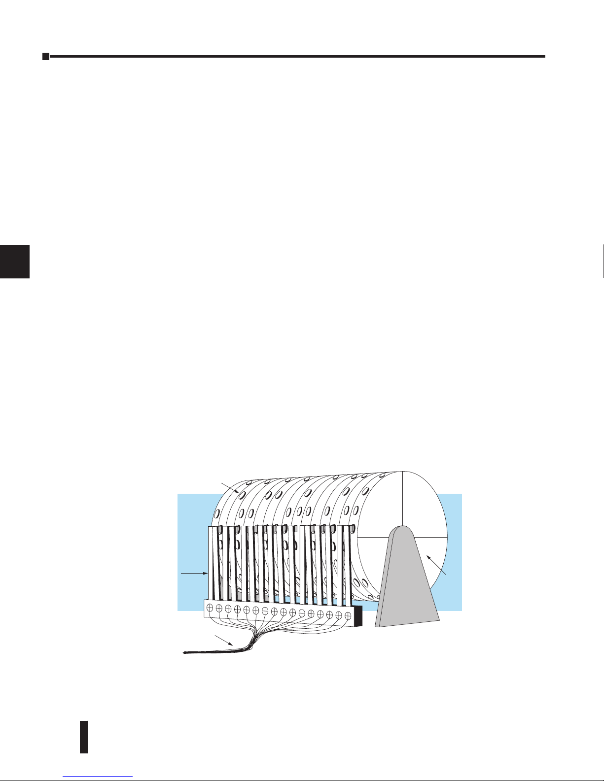
DL06 Micro PLC User Manual, 3rd Edition, Rev. D
6-2
Chapter 6: Drum Instruction Programming
1
2
3
4
5
6
7
8
9
10
11
12
13
14
A
B
C
D
Introduction
Purpose
The Event Drum (EDRUM) instruction in the DL06 CPU electronically simulates an
electro-mechanical drum sequencer. The instruction offers enhancements to the basic
principle, which we describe first.
Drum Terminology
Drum instructions are best suited for repetitive processes that consist of a finite number of
steps. They can do the work of many rungs of ladder logic with elegant simplicity. Therefore,
drums can save a lot of programming and debugging time.
We introduce some terminology associated with the drum instruction by describing the
original mechanical drum shown below. The mechanical drum generally has pegs on its
curved surface. The pegs are populated in a particular pattern, representing a set of desired
actions for machine control. A motor or solenoid rotates the drum a precise amount at
specific times. During rotation, stationary wipers sense the presence of pegs (present = on,
absent = off). This interaction makes or breaks electrical contact with the wipers, creating
electrical outputs from the drum. The outputs are wired to devices on a machine for On/Off
control.
Drums usually have a finite number of positions within one rotation, called steps. Each step
represents some process step. At powerup, the drum resets to a particular step. The drum
rotates from one step to the next based on a timer, or on some external event. During special
conditions, a machine operator can manually increment the drum step using a jog control
on the drum’s drive mechanism. The contact closure of each wiper generates a unique on/
off pattern called a sequence, designed for controlling a specific machine. Because the drum
is circular, it automatically repeats the sequence once per rotation. Applications vary greatly,
and a particular drum may rotate once per second, or as slowly as once per week.
Electronic drums provide the benefits of mechanical drums and more. For example, they have
a preset feature that is impossible for mechanical drums: The preset function lets you move
from the present step directly to any other step on command!
Drum
Outputs
Wipers
Pegs
Page 31
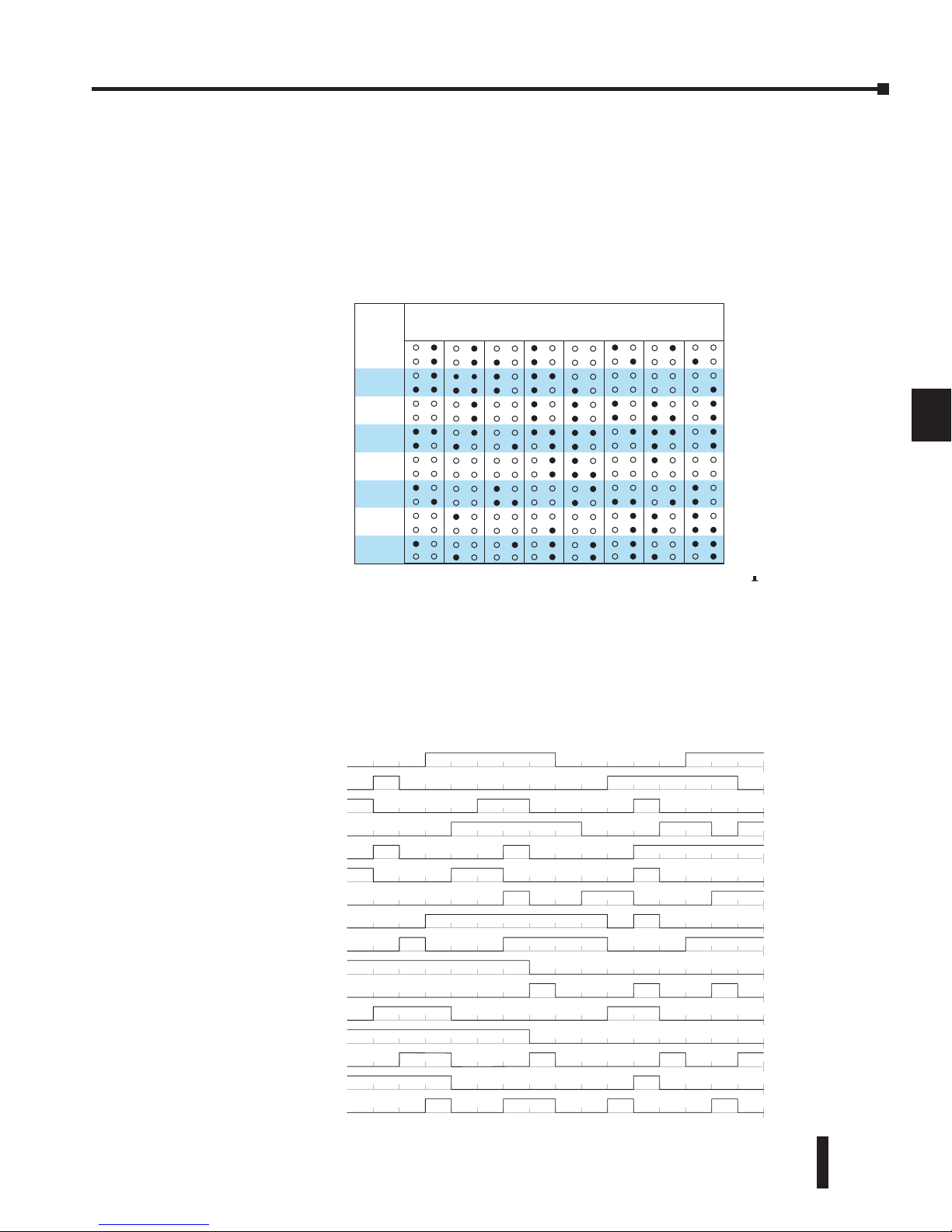
DL06 Micro PLC User Manual, 3rd Edition, Rev. D
6-3
Chapter 6: Drum Instruction Programming
1
2
3
4
5
6
7
8
9
10
11
12
13
14
A
B
C
D
Drum Chart Representation
For editing purposes, the electronic drum is presented in chart form in DirectSOFT and
in this manual. Imagine slicing the surface of a hollow drum cylinder between two rows of
pegs, then pressing it flat. Now you can view the drum as a chart as shown below. Each row
represents a step, numbered 1 through 16. Each column represents an output, numbered 0
through 15 (to match word bit numbering). The solid circles in the chart represent pegs (On
state) in the mechanical drum, and the open circles are empty peg sites (Off state).
Output
Sequences
The mechanical drum sequencer derives its name from sequences of control changes on its
electrical outputs. The following figure shows the sequence of On/Off controls generated
by the drum pattern above. Compare the two, and you will find that they are equivalent! If
you can see their equivalence, you are well on your way to understanding drum instruction
operation.
1
STEP
2
3
4
5
6
7
8
9
10
11
12
13
14
15
16
1 2 3 4 5 6 7 8 9101112131415 0
OUTPUTS
0
0
1
1
0
1
2
0
1
3
0
1
4
0
1
5
0
1
6
0
1
7
0
1
8
0
1
9
0
1
10
0
1
11
0
1
12
0
1
13
0
1
14
0
1
15
0
1
Output
12345678910 11 12 13 14 15 16
Step
Page 32
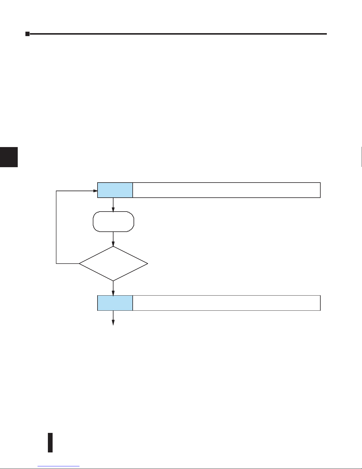
DL06 Micro PLC User Manual, 3rd Edition, Rev. D
6-4
Chapter 6: Drum Instruction Programming
1
2
3
4
5
6
7
8
9
10
11
12
13
14
A
B
C
D
Step Transitions
Drum Instruction Types
There are two types of Drum instructions in the DL06 CPU:
• Timed Drum with Discrete Outputs (DRUM)
• Time and Event Drum with Discrete Outputs (EDRUM)
The two drum instructions include time-based step transitions, and the EDRUM includes
event-based transitions as well. Each drum has 16 steps, and each step has 16 outputs. Refer
to the figure below. Each output can be either a Y or C coil, offering programming flexibility.
We assign Step 1 an arbitrary unique output pattern.
Timer-Only Transitions
Drums move from one step to another based on time and/or an external event (input). Each
step has its own transition condition which you assign during the drum instruction entry.
The figure below shows how timer-only transitions work.
The drum stays in Step 1 for a specific duration (user-programmable). The timebase of the
timer is programmable, from 0.01 seconds to 99.99 seconds. This establishes the resolution,
or the duration of each “tick of the clock.” Each step uses the same timebase, but has its own
unique counts per step, which you program. When the counts for Step 1 have expired, then
the drum moves to Step 2. The outputs change immediately to match the new pattern for
Step 2.
The drum spends a specific amount of time in each step, given by the formula:
Time in step = 0.01 seconds X Timebase x Counts per step
F fff
F
f
F
ffff
FF
fff
Step 1 Outputs:
fff
F
ffff
FFfF
ff
F FStep 2 Outputs :
Hascountsper
expired
?
No
Ye
s
Increment
count timer
Usenext transition criteria
step
Page 33
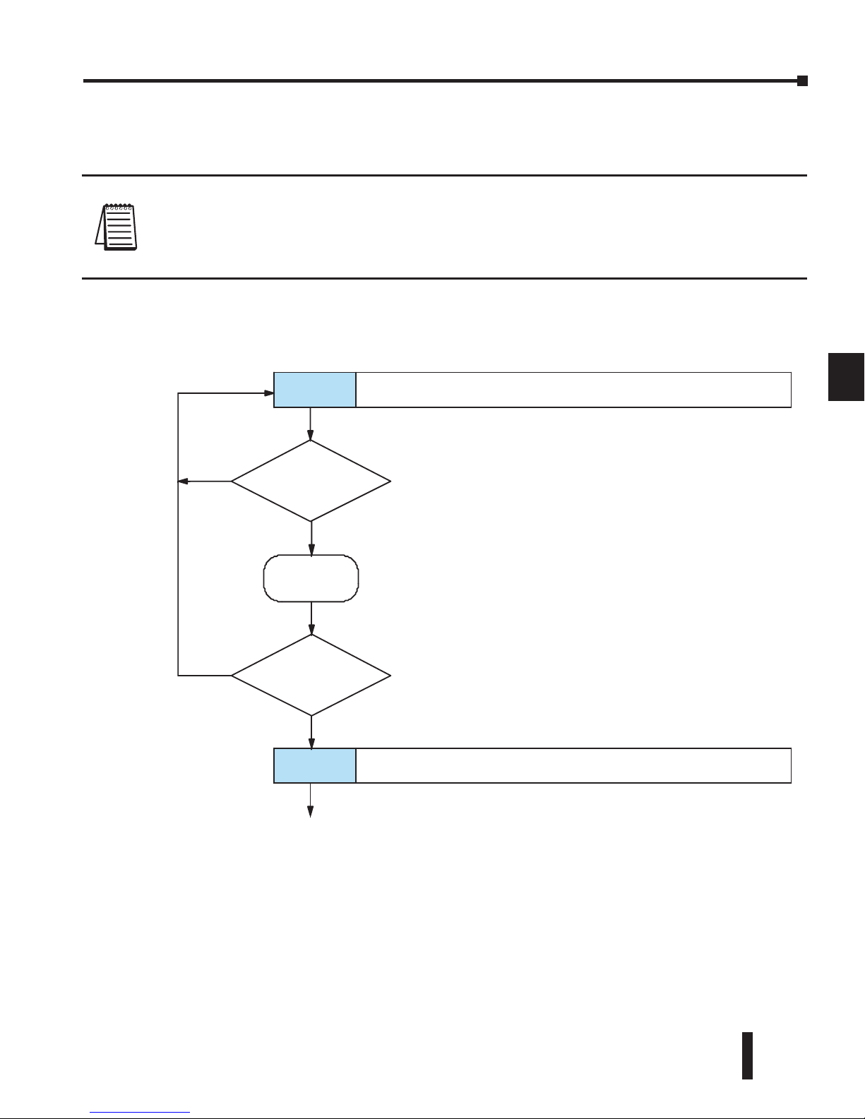
DL06 Micro PLC User Manual, 3rd Edition, Rev. D
6-5
Chapter 6: Drum Instruction Programming
1
2
3
4
5
6
7
8
9
10
11
12
13
14
A
B
C
D
For example, if you program a 5 second time base and 12 counts for Step 1, then the drum
will spend 60 seconds in Step 1. The maximum time for any step is given by the formula:
Max Time per step = 0.01 seconds X 9999 X 9999
= 999,800 seconds = 277.7 hours = 11.6 days
NOTE: When first choosing the timebase resolution, a good rule of thumb is to make it about 1/10
the duration of the shortest step in your drum. Then you will be able to optimize the duration of
that step in 10% increments. Other steps with longer durations allow optimizing by even smaller
increments (percentage-wise). Also, note that the drum instruction executes once per CPU scan.
Therefore, it is pointless to specify a drum timebase that is much faster than the CPU scan time.
Timer and Event Transitions
Step transitions may also occur based on time and/or external events. The figure below shows
how step transitions work in these cases.
When the drum enters Step 1, it sets the output pattern as shown. Then it begins polling the
external input programmed for that step. You can define event inputs as X, Y, or C discrete
point types. Suppose we select X0 for the Step 1 event input. If X0 is off, then the drum
remains in Step 1. When X0 is On, the event criteria is met and the timer increments. The
timer increments as long as the event (X0) remains true. When the counts for Step 1 have
expired, then the drum moves to Step 2. The outputs change immediately to match the new
pattern for Step 2.
Is Step event
true?
F f
ff
F
f
F
ffff
FF
fffStep 1 Outputs:
ff
f
F
ffff
FFfF
ff
F F
Step 2 Outputs:
No
Ye
s
Increment
counttime
r
Hasstep
counts expire d
?
N
o
Ye
s
Usenexttransitioncriteria
Page 34
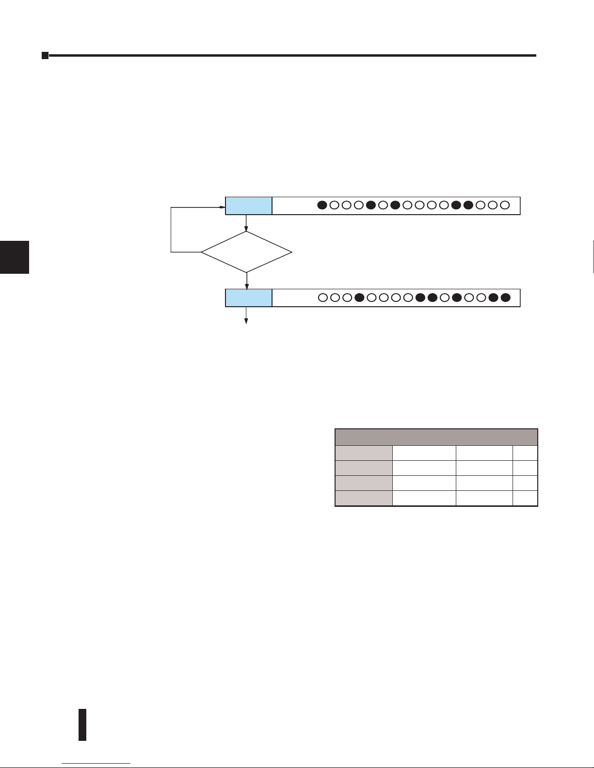
DL06 Micro PLC User Manual, 3rd Edition, Rev. D
6-6
Chapter 6: Drum Instruction Programming
1
2
3
4
5
6
7
8
9
10
11
12
13
14
A
B
C
D
Event-Only Transitions
Step transitions do not require both the event and the timer criteria programmed for each
step. You have the option of programming just one of the two, and even mixing transition
types among all the steps of the drum. For example, you might want Step 1 to transition on
an event, Step 2 to transition on time only, and Step 3 to transition on both time and an
event. Furthermore, you may elect to use only part of the 16 steps, and only part of the 16
outputs.
Counter Assignments
Each drum instruction uses the resources of four counters in the CPU. When programming
the drum instruction, you select the first counter number. The drum also uses the next three
counters automatically. The counter bit associated with the first counter turns on when the
drum has completed its cycle, going off when the drum is reset. These counter values and the
counter bit precisely indicate the progress of the drum instruction, and can be monitored by
your ladder program.
Suppose we program a timer drum to have 8
steps, and we select CT10 for the counter number
(remember, counter numbering is in octal).
Counter usage is shown to the right. The right
column holds typical values, interpreted below.
CT10 shows that we are at the 1528th count in
the current step, which is step 4 (shown in CT13). If we have programmed step 4 to have
3000 counts, then the step is just over half completed. CT11 is the count timer, shown in
units of 0.01 seconds. So, each least-significant-digit change represents 0.01 seconds. The
value of 200 means that we have been in the current count (1528) for 2 seconds (0.01 x 200).
Finally, CT12 holds the preset step value which was programmed into the drum instruction.
When the drum’s Reset input is active, it presets to step 1 in this case. The value of CT12
changes only if the ladder program writes to it, or the drum instruction is edited and the
program is restarted. Counter bit CT10 turns on when the drum cycle is complete, and turns
off when the drum is reset.
Chapter 6: Drum Instruction Programming
Counter Assignments
CT10
Counts in step V1010 1528
CT11
Timer Value V1011 0200
CT12
Preset Step V1012 0001
CT13
Current Step V1013 0004
Is Step event
true?
Step 1Outputs:
Step 2Outputs:
No
Ye
s
Use nexttransitioncriteri
a
Page 35
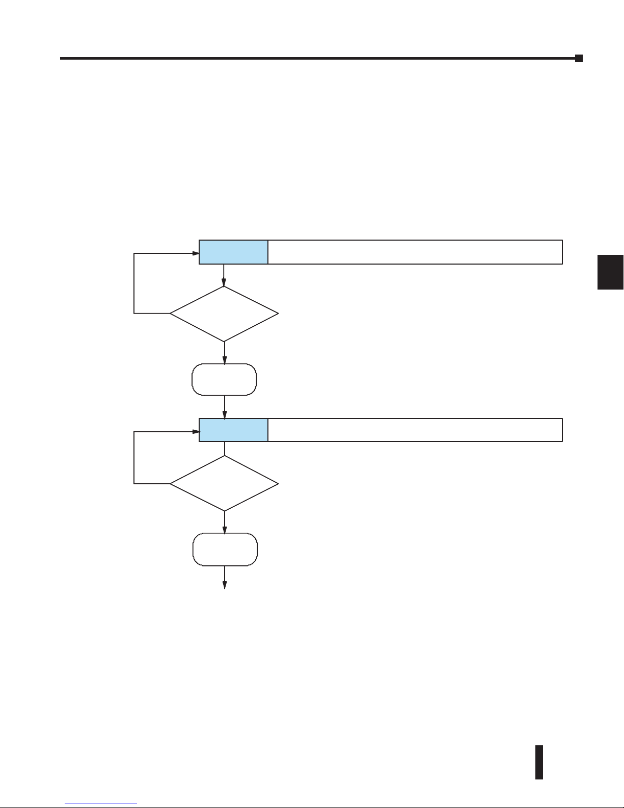
DL06 Micro PLC User Manual, 3rd Edition, Rev. D
6-7
Chapter 6: Drum Instruction Programming
1
2
3
4
5
6
7
8
9
10
11
12
13
14
A
B
C
D
Last Step Completion
The last step in a drum sequence may be any step number, since partial drums are valid. Refer
to the following figure. When the transition conditions of the last step are met, the drum
sets the counter bit corresponding to the counter named in the drum instruction box (such
as CT10). Then it moves to a final “drum complete” state. The drum outputs remain in the
pattern defined for the last step. Having finished a drum cycle, the Start and Jog inputs have
no effect at this point. The drum leaves the “drum complete” state when the Reset input
becomes active (or on a program-to–run mode transition). It resets the drum complete bit
(such as CT10), and then goes directly to the appropriate step number defined as the preset
step.
Aretra ns ition
conditions met?
FF
F
fffFffFf
FFFfFLast step Outputs:
FF
F
fff
F
ffFf
FFF
f
F
Complete Outputs :
No
Ye
s
Go to Preset Ste p
Set
CT10 = 1
R
es et Input
Active
?
No
Ye
s
Reset
(Timer and/or
Eventcriteria)
SetDrumCompletebit
ResetDrumCompletebit
CT10 = 0
Page 36
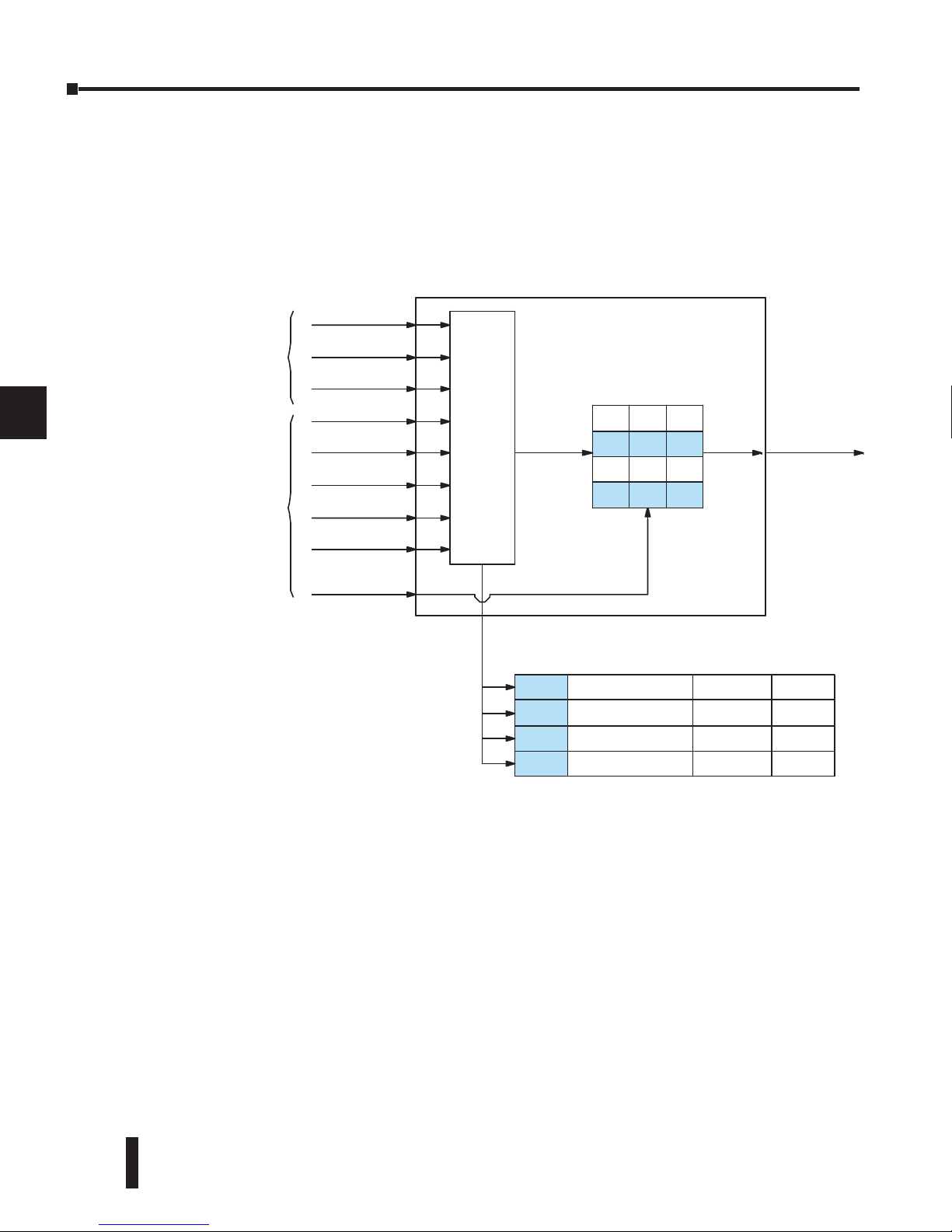
DL06 Micro PLC User Manual, 3rd Edition, Rev. D
6-8
Chapter 6: Drum Instruction Programming
1
2
3
4
5
6
7
8
9
10
11
12
13
14
A
B
C
D
Overview of Drum Operation
Drum Instruction Block Diagram
The drum instruction utilizes various inputs and outputs in addition to the drum pattern
itself. Refer to the figure below.
The drum instruction accepts several inputs for step control, the main control of the drum.
The inputs and their functions are:
• Start – The Start input is effective only when Reset is off. When Start is on, the drum timer runs if
it is in a timed transition, and the drum looks for the input event during event transitions. When
Start is off, the drum freezes in its current state (Reset must remain off), and the drum outputs
maintain their current on/off pattern.
• Jog – The jog input is only effective when Reset is off (Start may be either on or off). The jog input
increments the drum to the next step on each off-to-on transition (only EDRUM supports the jog
input).
• Reset – The Reset input has priority over the Start input. When Reset is on, the drum moves to its
preset step. When Reset is off, then the Start input operates normally.
• Preset Step – A step number from 1 to 16 that you define (typically is step 1). The drum moves to
this step whenever Reset is on, and whenever the CPU first enters run mode.
ffFfff
ffffff
ffffFf
FFfFFf
fFFfFf
fFFfFF
fFffFF
fFFffF
St ep
Po inter
Drum
DRUM INSTRUCTION
BlockDiagram
Inputs Outputs
Countsinstep xxxx
TimerValue xxxx
Preset Step xxxx
Current Step xxxx
Counter Assignments
Events
Realtime
Input s
(fromladder)
Programming
Selections
Start
Jog
Reset
Preset Step
Counts/Step
Timebase
Counter #
Pattern
Step
Control
Final
Drum
Outputs
CTA10
CTA11
CTA12
CTA13
V1010
V1011
V1012
V1013
Page 37
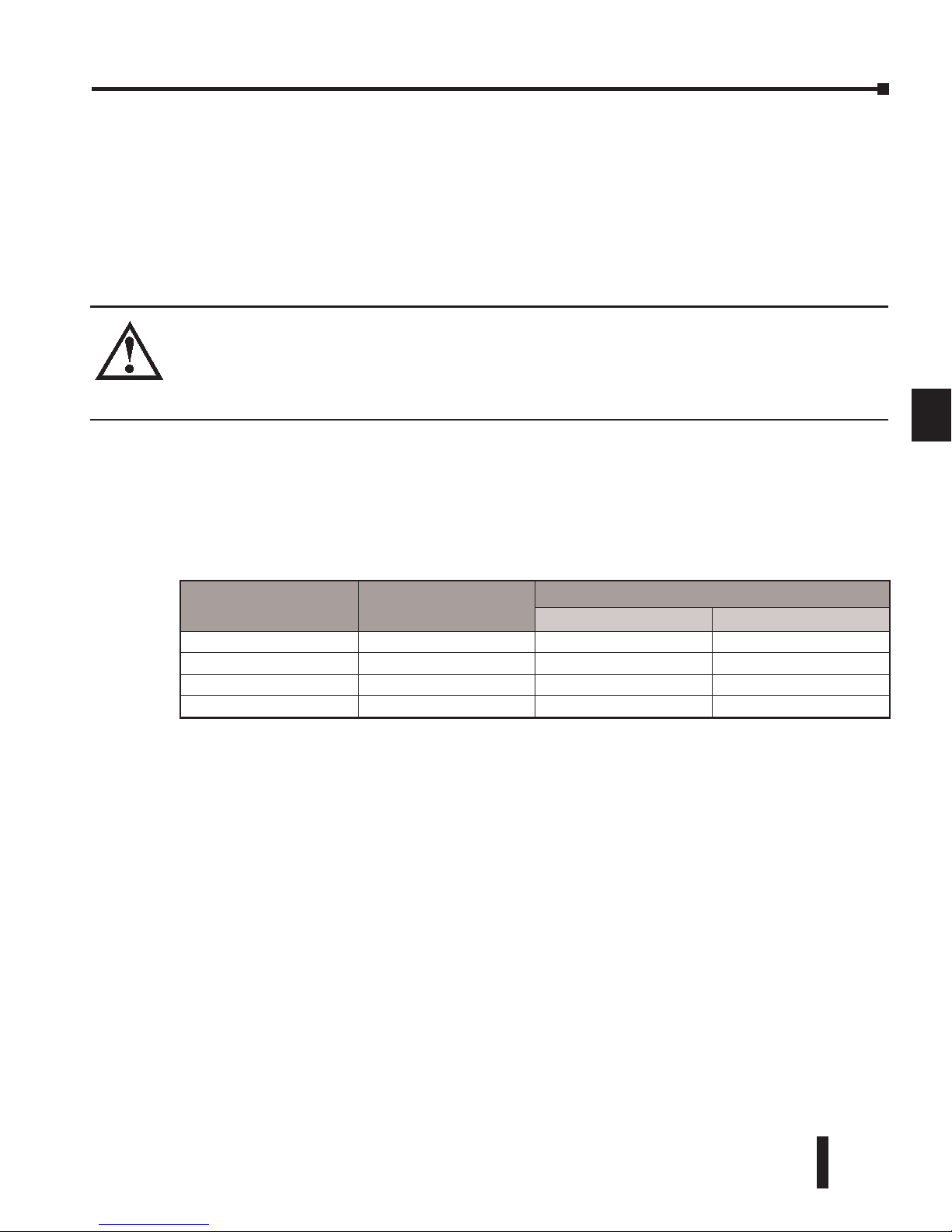
DL06 Micro PLC User Manual, 3rd Edition, Rev. D
6-9
Chapter 6: Drum Instruction Programming
1
2
3
4
5
6
7
8
9
10
11
12
13
14
A
B
C
D
• Counts/Step – The number of timer counts the drum spends in each step. Each step has its own
counts parameter. However, programming the counts/step is optional.
• Timer Value – the current value of the counts/step timer.
• Counter # – The counter number specifies the first of four consecutive counters which the drum
uses for step control. You can monitor these to determine the drum’s progress through its control
cycle. The DL06 has 128 counters (CT0 – CT177 in octal).
• Events – Either an X, Y, C, S, T, or CT type discrete point serves as step transition inputs. Each
step has its own event. However, programming the event is optional.
WARNING: The outputs of a drum are enabled any time the CPU is in Run Mode. The Start Input
does not have to be on, and the Reset input does not disable the outputs. Upon entering Run
Mode, drum outputs automatically turn on or off according to the pattern of the current step of
the drum. This initial step number depends on the counter memory configuration: non-retentive
versus retentive.
Powerup State of Drum Registers
The choice of the starting step on powerup and program-to-run mode transitions are
important to consider for your application. Please refer to the following chart. If the counter
memory is configured as non-retentive, the drum is initialized the same way on every
powerup or program-to-run mode transition. However, if the counter memory is configured
to be retentive, the drum will stay in its previous state.
Applications with relatively fast drum cycle times typically will need to be reset on powerup,
using the non-retentive option. Applications with relatively long drum cycle times may need
to resume at the previous point where operations stopped, using the retentive case. The
default option is the retentive case. This means that if you initialize scratchpad V-memory,
the memory will be retentive.
Counter Number Function
Initialization on Powerup
Non-Retentive Case Retentive Case
CTA(n) Current Step Count Initialize = 0 Use Previous (no change)
CTA(n + 1) Counter Timer Value Initialize = 0 Use Previous (no change)
CTA(n + 2) Preset Step Initialize = Preset Step # Use Previous (no change)
CTA(n + 3) Current Step # Initialize = Preset Step # Use Previous (no change)
Page 38
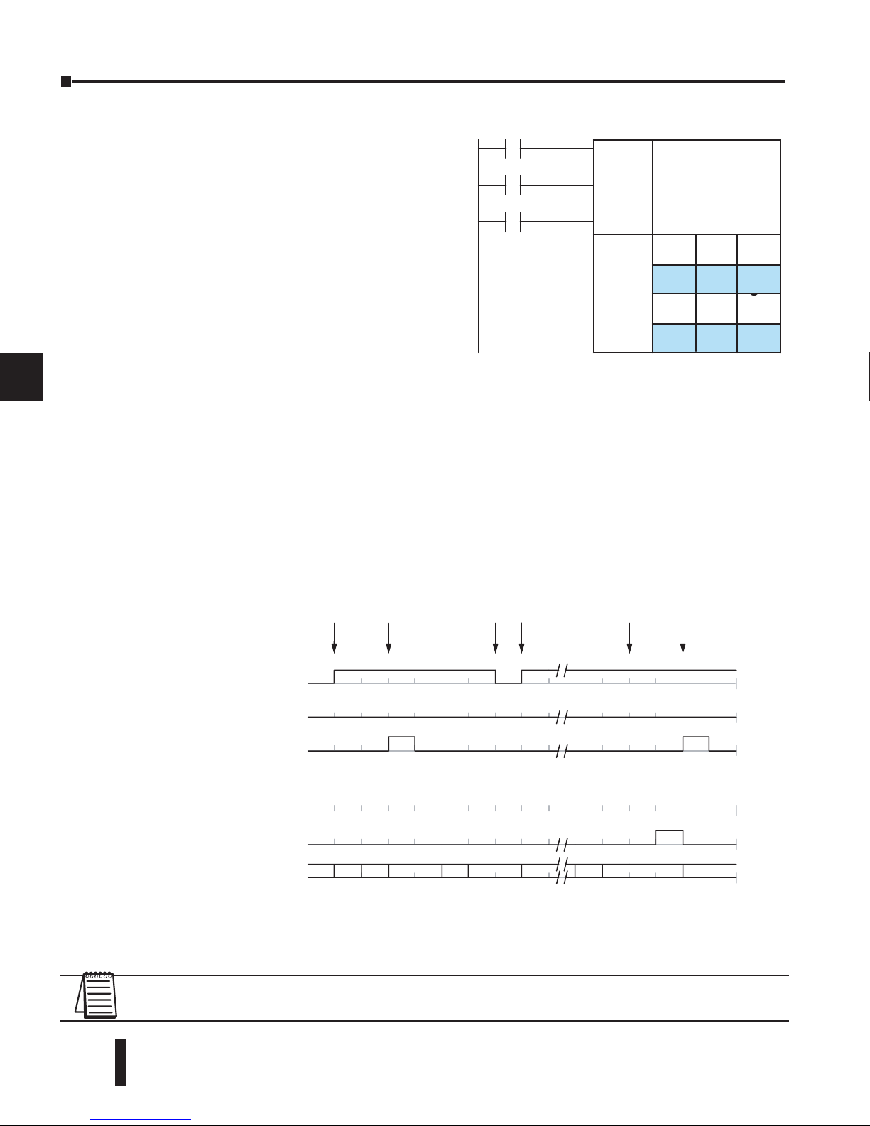
DL06 Micro PLC User Manual, 3rd Edition, Rev. D
6-10
Chapter 6: Drum Instruction Programming
1
2
3
4
5
6
7
8
9
10
11
12
13
14
A
B
C
D
Drum Control Techniques
Drum Control Inputs
Now we are ready to put together the concepts
on the previous pages and demonstrate general
control of the drum instruction box. The
drawing to the right shows a simplified generic
drum instruction. Inputs from ladder logic
control the Start, Jog, and Reset Inputs (only the
EDRUM instruction supports the Jog Input).
The first counter bit of the drum (CT10, for
example) indicates the drum cycle is done.
The timing diagram below shows an arbitrary
timer drum input sequence and how the drum responds. As the CPU enters Run mode it
initializes the step number to the preset step number (typically it is Step 1). When the Start
input turns on the drum begins running, waiting for an event and/or running the timer
(depends on the setup).
After the drum enters Step 2, Reset turns On while Start is still On. Since Reset has priority
over Start, the drum goes to the preset step (Step 1). Note that the drum is held in the preset
step during Reset, and that step does not run (respond to events or run the timer) until Reset
turns off.
After the drum has entered step 3, the Start input goes off momentarily, halting the drum’s
timer until Start turns on again.
When the drum completes the last step (Step 16 in this example), the Drum Complete bit
(CT10) turns on, and the step number remains at 16. When the Reset input turns on, it
turns off the Drum Complete bit (CT10), and forces the drum to enter the preset step.
NOTE: The timing diagram shows all steps using equal time durations. Step times can vary greatly,
depending on the counts/step programmed.
ffFfff
ffffff
ffffFf
FFfFFf
fFFfFf
fFFfFF
fFffFF
fFFffF
X0
X1
X2
ffFfff
ffffff
ffffFf
FFfFFf
fFFfFf
fFFfFF
fFffFF
fFFffF
X0
X1
X2
Start
Jog
Reset
Setup
Info
Outputs
Steps
Start
0
1
Jog
0
1
Step #
Drum
0
1
Inputs
112112334... 15 16 16 16 11
Dr um Statu
s
Start
drum
Reset
drum
Hold
drum
Resume
drum
Drum
Complete
Reset
drum
0
1
Outputs(x16
)
Reset
0
1
Complete (CT10)
Page 39
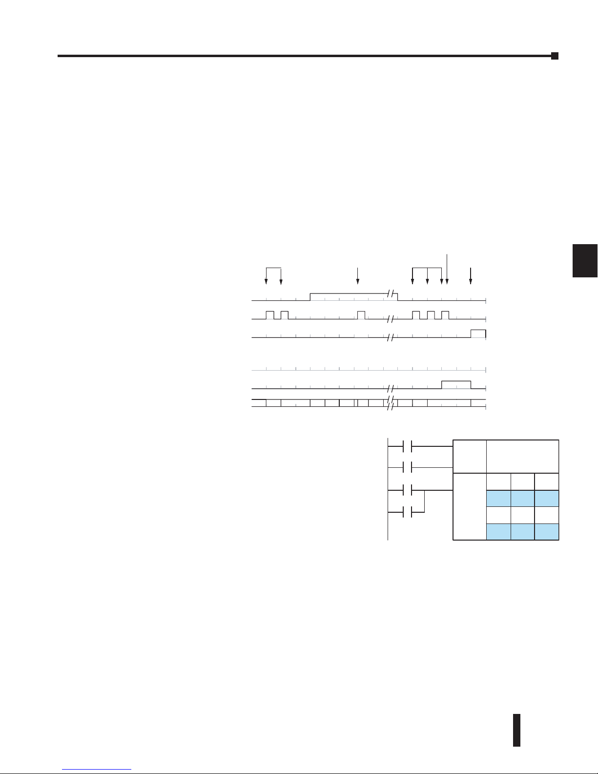
DL06 Micro PLC User Manual, 3rd Edition, Rev. D
6-11
Chapter 6: Drum Instruction Programming
1
2
3
4
5
6
7
8
9
10
11
12
13
14
A
B
C
D
In the figure below, we focus on how the Jog input works on event drums. To the left of the
diagram, note that the off-to-on transitions of the Jog input increments the step. Start may
be either on or off (however, Reset must be off). Two jogs takes the drum to step three. Next,
the Start input turns on, and the drum begins running normally. During step 6 another Jog
input signal occurs. This increments the drum to step 7, setting the timer to 0. The drum
begins running immediately in step 7, because Start is already on. The drum advances to step
8 normally.
As the drum enters step 14, the Start input turns off. Two more Jog signals moves the drum
to step 16. However, note that a third Jog signal is required to move the drum through step
16 to “drum complete”. Finally, a Reset input signal arrives which forces the drum into the
preset step and turns off the drum complete bit.
Self-Resetting Drum
Applications often require drums that automatically
start over once they complete a cycle. This is easily
accomplished, using the drum complete bit. In the figure
to the right, the drum instruction setup is for CT10, so
we logically OR the drum complete bit (CT10) with
the Reset input. When the last step is done, the drum
turns on CT10 which resets itself to the preset step, also
resetting CT10. Contact X2 still works as a manual reset.
Initializing Drum Outputs
The outputs of a drum are enabled any time the CPU is in run mode. On program-to-run
mode transitions, the drum goes to the preset step, and the outputs energize according to the
pattern of that step. If your application requires all outputs to be off at powerup, make the
preset step in the drum a “reset step”, with all outputs off.
Using Complex Event Step Transitions
Each event-based transition accepts only one contact reference for the event. However, this
does not limit events to just one contact. Just use a control relay contact such as C0 for the
step transition event. Elsewhere in ladder logic, you may use C0 as an output coil, making it
dependent on many other events (contacts).
Start
0
1
Reset
0
1
Step #
Drum
Complete (CT0)
0
1
Inputs
12333456,78... 14 15 16 16 16 1
Drum Status
Reset
drum
Jog
drum
0
1
Outputs(x16)
Jog
0
1
Jog
dru
m
Jog
drum
Drum
Completed
ffFfff
ffffff
ffffFf
FFfFFf
fFFfFf
fFFfFF
fFffFF
fFFffF
Outputs
Setup
Info .
X0
X2
R eset
X1
Start
Start
Steps
CT10
Page 40
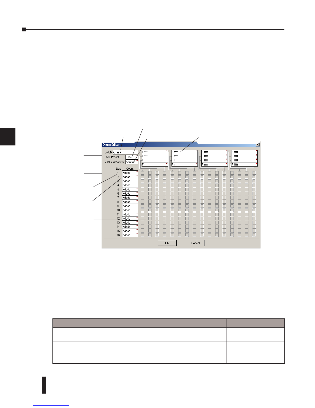
DL06 Micro PLC User Manual, 3rd Edition, Rev. D
6-12
Chapter 6: Drum Instruction Programming
1
2
3
4
5
6
7
8
9
10
11
12
13
14
A
B
C
D
Drum Instruction
The DL06 drum instructions may be programmed using DirectSOFT, or for the EDRUM
instruction only you can use a handheld programmer (firmware version v2.21 or later). This
section covers entry using DirectSOFT for all instructions plus the handheld mnemonics for
the EDRUM instruction.
Timed Drum with Discrete Outputs (DRUM)
The Timed Drum with Discrete Outputs is the most basic of the DL06’s drum instructions.
It operates according to the principles covered on the previous pages. Below is the instruction
in chart form as displayed by DirectSOFT.
The Timed Drum features 16 steps and 16 outputs. Step transitions occur only on a timed
basis, specified in counts per step. Unused steps must be programmed with “counts per
step”=0 (this is the default entry). The discrete output points may be individually assigned as
X, Y, or C types, or may be left unused. The output pattern may be edited graphically with
DirectSOFT.
Whenever the Start input is energized, the drum’s timer is enabled. It stops when the last step
is complete, or when the Reset input is energized. The drum enters the preset step chosen
upon a CPU program-to-run mode transition, and whenever the Reset input is energized.
Drum Parameters Field Data Types Ranges
Counter Number aaa -- 0 --174
Preset Step bb K 1 -- 16
Timer base cccc K 0 -- 99.99 seconds
Counts per step dddd K 0 -- 9999
Discrete Outputs Fffff X, Y, C see memory map
Step Number
Start
Reset
Counts per Step
Output Pattern
l= Off, L= On
Counter Number
Step Preset
Timebase
Discrete Output Assignment
{
Control
Inputs
Direct SOFT 5 Display
Page 41
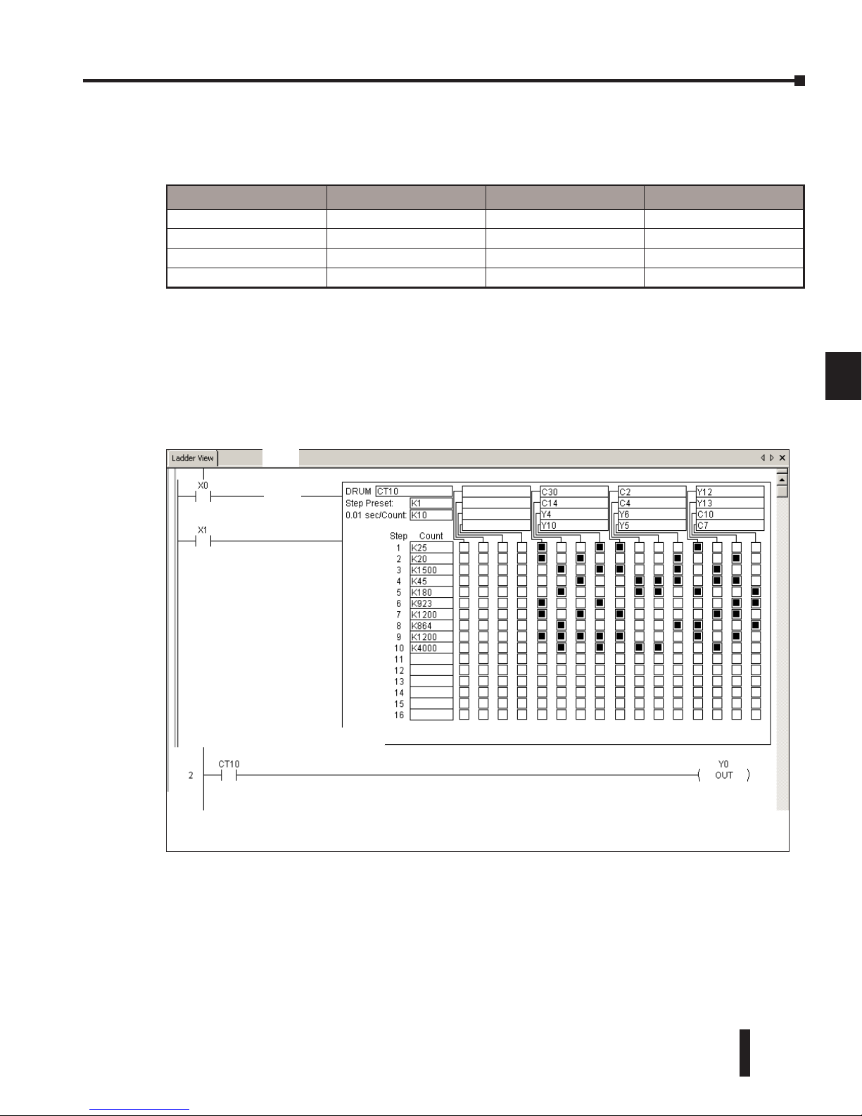
DL06 Micro PLC User Manual, 3rd Edition, Rev. D
6-13
Chapter 6: Drum Instruction Programming
1
2
3
4
5
6
7
8
9
10
11
12
13
14
A
B
C
D
Drum instructions use four counters in the CPU. The ladder program can read the counter
values for the drum’s status. The ladder program may write a new preset step number to
CTA(n+2) at any time. However, the other counters are for monitoring purposes only.
The following ladder program shows the DRUM instruction in a typical ladder program, as
shown by DirectSOFT. Steps 1 through 10 are used, and twelve of the sixteen output points
are used. The preset step is step 1. The timebase runs at (K10 x 0.01) = 0.1 second per count.
Therefore, the duration of step 1 is (25 x 0.1) = 2.5 seconds. In the last rung, the Drum
Complete bit (CT10) turns on output Y0 upon completion of the last step (step 10). A drum
reset also resets CT10.
Counter Number Ranges of (n) Function Counter Bit Function
CTA(n) 0 -- 174 Counts in step CT(n) = Drum Complete
CTA( n+1) 1 -- 175 Timer value CT(n+1) = (not used)
CTA( n+2) 2 -- 176 Preset Step CT(n+2) = (not used)
CTA( n+3) 3 -- 177 Current Step CT(n+3) = (not used)
Direct SOFT 5 Display
Start
Reset
Drum Complete
Page 42
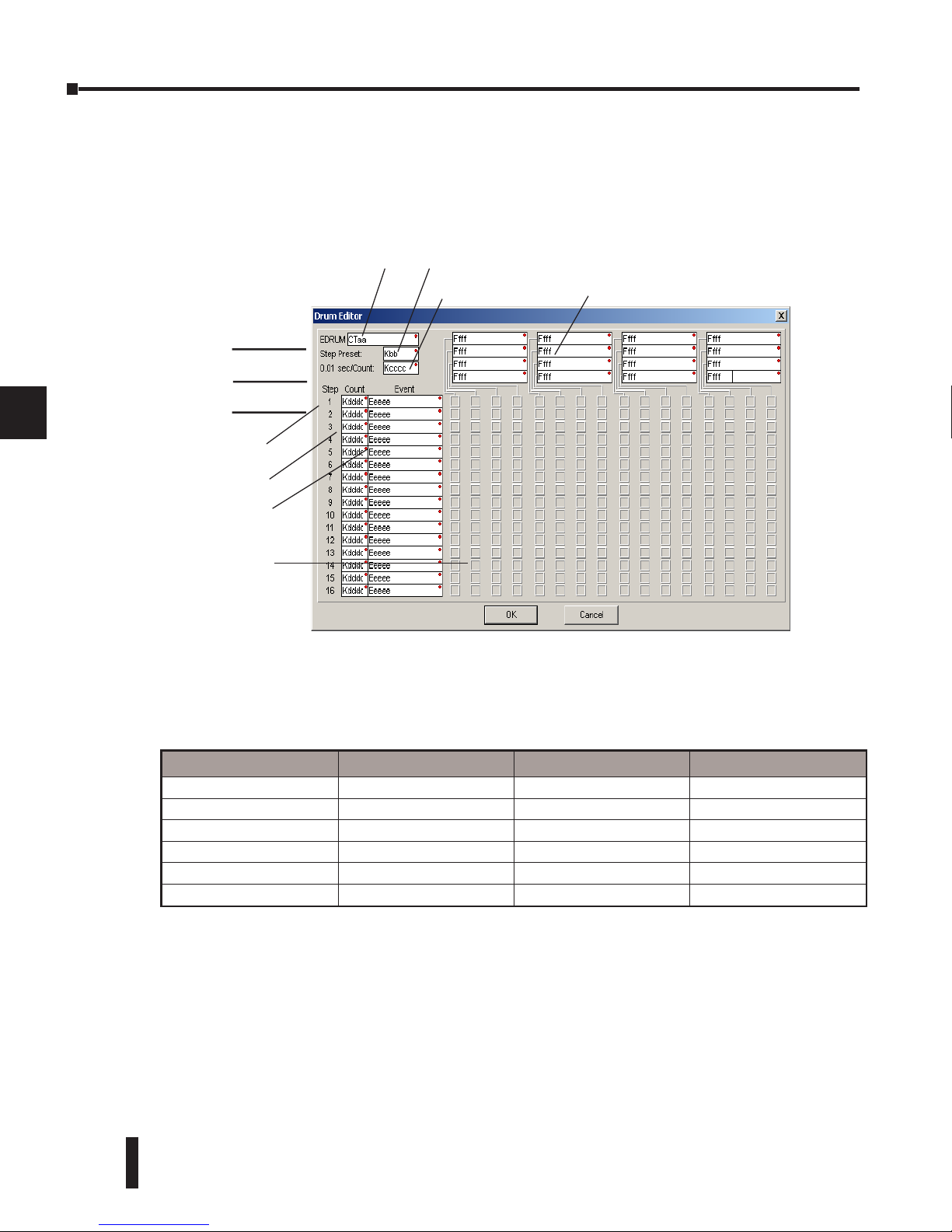
DL06 Micro PLC User Manual, 3rd Edition, Rev. D
6-14
Chapter 6: Drum Instruction Programming
1
2
3
4
5
6
7
8
9
10
11
12
13
14
A
B
C
D
Event Drum (EDRUM)
The Event Drum (EDRUM) features time-based and event-based step transitions. It operates
according to the general principles of drum operation covered in the beginning of this
chapter. Below is the instruction as displayed by DirectSOFT.
The Event Drum features 16 steps and 16 discrete outputs. Step transitions occur on timed
and/or event basis. The jog input also advances the step on each off-to-on transition. Time
is specified in counts per step, and events are specified as discrete contacts. Unused steps and
events must be left blank. The discrete output points may be individually assigned.
Whenever the Start input is energized, the drum’s timer is enabled. As long as the event is
true for the current step, the timer runs during that step. When the step count equals the
counts per step, the drum transitions to the next step. This process stops when the last step is
complete, or when the Reset input is energized. The drum enters the preset step chosen upon
a CPU program-to-run mode transition, and whenever the Reset input is energized.
Drum Parameters Field Data Types Ranges
Counter Number aa -- 0 -- 174
Preset Step bb K 1 -- 16
Timer base cccc K 0 -- 99.99 seconds
Counts per step dddd K 0 -- 9999
Event Eeeee X, Y, C, S, T, CT, SP see memory map
Discrete Outputs ffff X, Y, C see memory map
Direct SOFT 5 Display
Step Number
Start
Jog
Counts per Step
Output Pattern
l= Off, L= On
Counter Number
Step Preset
Timebase
Discrete Output Assignment
{
Control
Inputs
Reset
Event per Step
Page 43
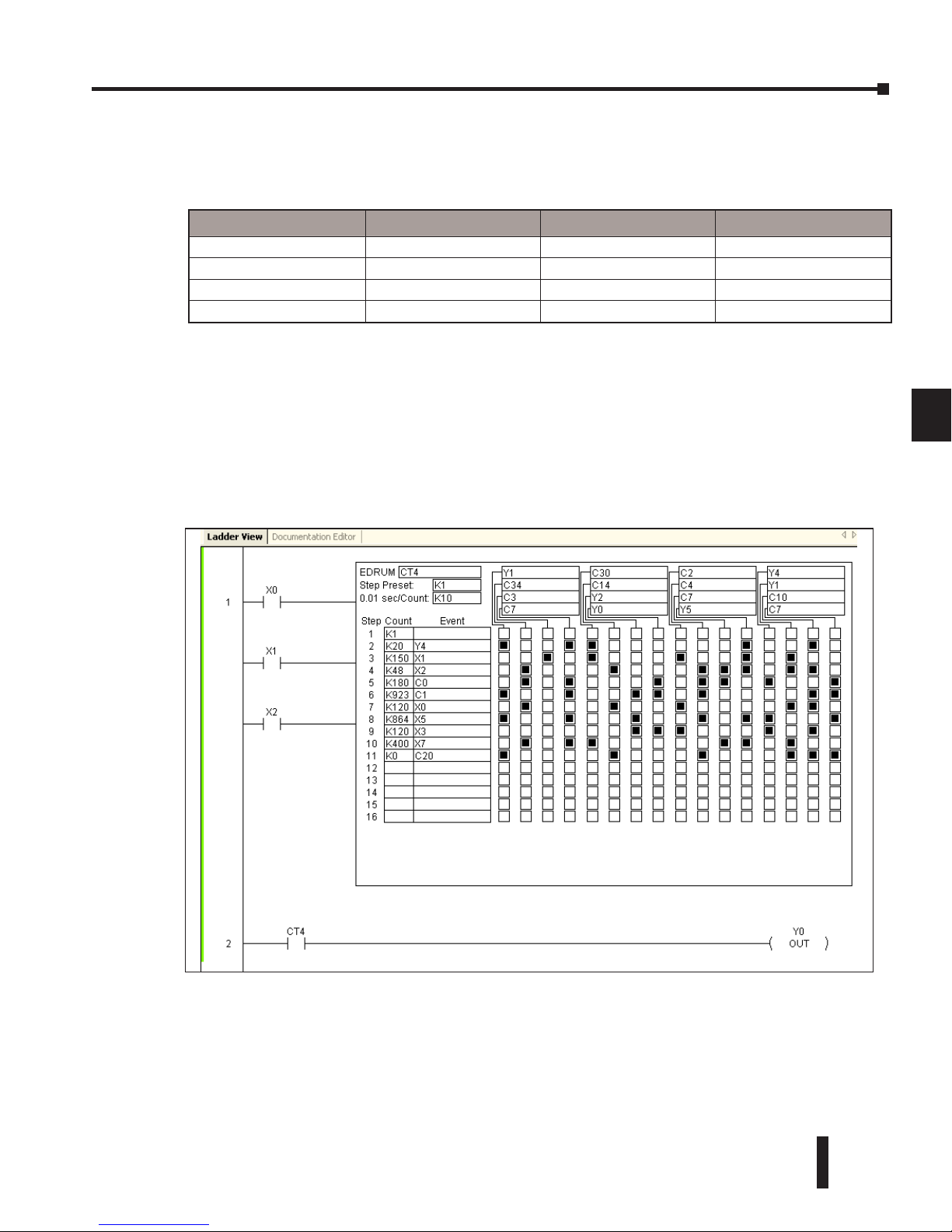
DL06 Micro PLC User Manual, 3rd Edition, Rev. D
6-15
Chapter 6: Drum Instruction Programming
1
2
3
4
5
6
7
8
9
10
11
12
13
14
A
B
C
D
Drum instructions use four counters in the CPU. The ladder program can read the counter
values for the drum’s status. The ladder program may write a new preset step number to
CTA(n+2) at any time. However, the other counters are for monitoring purposes only.
The following ladder program shows the EDRUM instruction in a typical ladder program,
as shown by DirectSOFT. Steps 1 through 11 are used, and all sixteen output points are
used. The preset step is step 1. The timebase runs at (K10 x 0.01) = 0.1 second per count.
Therefore, the duration of step 1 is (1 x 0.1) = 0.1 second. Note that step 1 is time-based only
(event is left blank). And, the output pattern for step 1 programs all outputs off, which is a
typically desirable powerup condition. In the last rung, the Drum Complete bit (CT4) turns
on output Y0 upon completion of the last step (step 11). A drum reset also resets CT4.
Counter Number Ranges of (n) Function Counter Bit Function
CTA(n) 0 -- 174 Counts in step CT(n )= Drum Complete
CTA( n+1) 1 -- 175 Timer value CT(n+1) = (not used)
CTA( n+2) 2 -- 176 Preset Step CT(n+2) = (not used)
CTA( n+3) 3 -- 177 Current Step CT(n+3) = (not used)
START
JOG
RESET
DRUM COMPLETE
Page 44
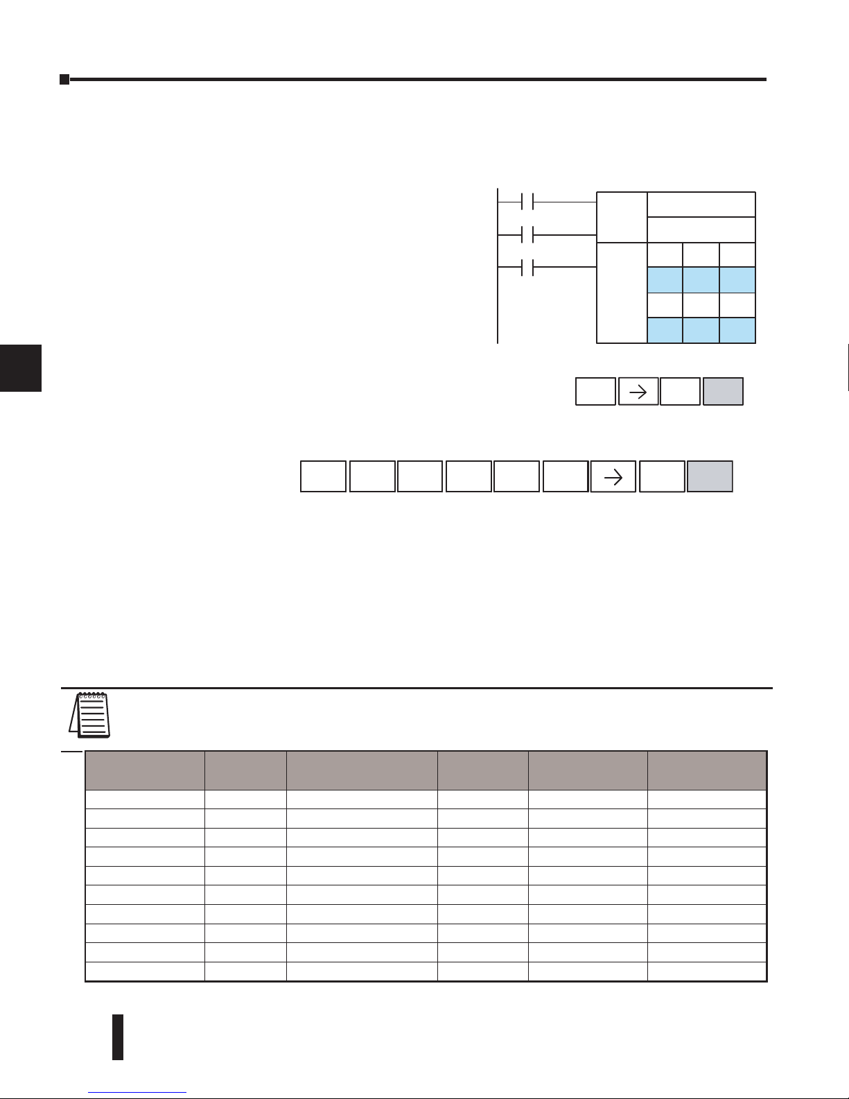
DL06 Micro PLC User Manual, 3rd Edition, Rev. D
6-16
Chapter 6: Drum Instruction Programming
1
2
3
4
5
6
7
8
9
10
11
12
13
14
A
B
C
D
Handheld Programmer Drum Mnemonics
The EDRUM instruction can also be programmed using a handheld programmer. This
section explains entry via the handheld programmer.
First, enter Store instructions for the ladder rungs
controlling the drum’s ladder inputs. In the example
to the right, the timer drum’s Start, Jog, and Reset
inputs are controlled by X0, X1 and X2 respectively.
The required keystrokes are listed beside the
mnemonic.
These keystrokes precede the EDRUM instruction
mnemonic. Note that the ladder rungs for Start, Jog,
and Reset inputs are not limited to being single–
contact rungs.
After the Store instructions, enter the EDRUM (using Counter CT0) as shown:
After entering the EDRUM mnemonic as above, the handheld programmer creates an input
form for all the drum parameters. The input form consists of approximately fifty or more
default mnemonic entries containing DEF (define) statements. The default mnemonics are
already input for you, so they appear automatically. Use the NXT and PREV keys to move
forward and backward through the form. Only the editing of default values is required, thus
eliminating many keystrokes. The entries required for the basic timer drum are in the chart
below.
NOTE: Default entries for output points and events are “DEF 0000”, which means they are
unassigned. If you need to go back and change an assigned output as unused again, enter “K0000”.
The entry will again show as “DEF 0000”.
ffFfff
ffffff
ffffFf
FFfFFf
fFFfFf
fFFfFF
fFffFF
fFFffF
Outputs
X0
X1
Mask
Jog
Handheld Programmer Keys trok es
X
2
Reset
STR
$
0
A
ENT
Start
Setup
Info
Steps
Store X0
(Repeat for Store X1 and Store X2)
HandheldProgrammerKeystrokes
SHF
T
4
E
3
D
ORNRISGUORST
M
ENT
EDRUM CNT4
E
4
Drum
Parameters
Multiple
Entries
Mnemonic / Entry
Default
Mnemonic
Valid Data
Types
Ranges
Start Input -- STR (plus input rung) -- -- --
Jog Input -- STR (plus input rung) -- -- --
Reset Input -- STR (plus input rung) -- -- --
Drum Mnemonic -- DRUM CNT aa -- CT 0 -- 174
Preset Step 1 bb DEF K0000 K 1 -- 16
Timer base 1 cccc DEF K0000 K 1 -- 9999
Output points 16 ffff DEF 0000 X, Y, C see memory map
Counts per step 16 dddd DEF K0000 K 0 -- 9999
Events 16 dddd DEF K0000 X, Y, C, S, T, CT, SP see memory map
Output pattern 16 gggg DEF K0000 K 0 -- FFFF
Page 45
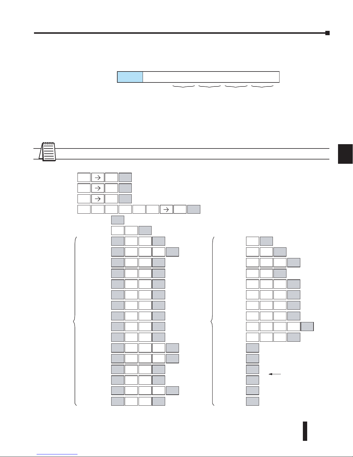
DL06 Micro PLC User Manual, 3rd Edition, Rev. D
6-17
Chapter 6: Drum Instruction Programming
1
2
3
4
5
6
7
8
9
10
11
12
13
14
A
B
C
D
Using the DRUM entry chart (two pages before), we show the method of entry for the
basic time/event drum instruction. First, we convert the output pattern for each step to the
equivalent hex number, as shown in the following example.
The following diagram shows the method for entering the previous EDRUM example on the
HHP. The default entries of the form are in parenthesis. After the drum instruction entry
(on the fourth row), the remaining keystrokes over-write the numeric portion of each default
DEF statement. NOTE: Drum editing requires Handheld Programmer firmware version
2.21 or later.
NOTE: You may use the NXT and PREV keys to skip past entries for unused outputs or steps.
f fffFffFfff
FFfF
f
1 Outputs:
015
091A
--converts to:
Step
HandheldProgr ammerKeystrokes
(DEF K0001)
Reset
Drum Inst.
(DEF 0000 )
(DEF 0000 )
(DEF 0000 )
(DEF K0000 )
Preset
Time Base
(DEF 0000 )
(DEF 0000 )
(DEF 0000 )
(DEF 0000 )
(DEF 0000 )
(DEF 0000 )
(DEF 0000 )
(DEF 0000 )
(DEF 0000 )
(DEF 0000 )
(DEF 0000 )
(DEF 0000 )
(DEF 0000 )
Outputs
(DEF K0000 )
(DEF K0000 )
(DEF K0000 )
(DEF K0000 )
(DEF K0000 )
(DEF K0000 )
(DEF K0000 )
(DEF K0000 )
(DEF K0000 )
(DEF K0000 )
(DEF K0000 )
(DEF K0000 )
(DEF K0000 )
(DEF K0000 )
(DEF K0000 )
(DEF K0000 )
skipover
unused steps
Jog
STR
$
0
A
STR
$
1
B
STR
$
2
C
SHFT
4E3DORNRISGUORST
M
ENT
4
E
6
G
NEXT
NEXT
ENT
ENT
ENT
SHFT
2
C
7
H
NEXT
SHFT
2
C
0
A
NEXT
1
B
SHFT
MLSY1
B
NEXT
SHFT
MLS
Y
NEXT
4
E
SHFT
MLSY5
F
NEXT
SHFT
MLSY6
G
NEXT
SHFT
2
C
4
E
NEXT
SHFT
2
C
2
C
NEXT
SHFT
MLS
Y
NEXT
0
A
SHFT
MLS
Y
NEXT
2
C
SHFT
2
C
1
B4E
NEXT
SHFT
2
C
NEXT
3
D0A
SHFT
MLS
Y
NEXT
6
G
SHFT
MLS
Y
NEXT
7
H
SHFT
2
C
3
D4E
NEXT
SHFT
MLSY1
B
NEXT
1
16
1
16
5
F
NEXT
2
C0A
NEXT
1
B5F
0
A
NEXT
4
E5F
NEXT
1
B8I
0
A
NEXT
9
J
2
C
3
D
NEXT
1
B
0
A
NEXT
2
C
8
I
6
G
4
E
NEXT
1
B2C
0
A0A
NEXT
4
E0A
0
A
NEXT
NEXT
NEXT
NEXT
NEXT
NEXT
NEXT
HandheldProgr ammerKeystrokescont’d
Start
Step
Counts/
Step
Note: You may use the NXT and PREV keys
to skip past entries for unused outputs or steps.
(Continued on next page )
E
4
Page 46
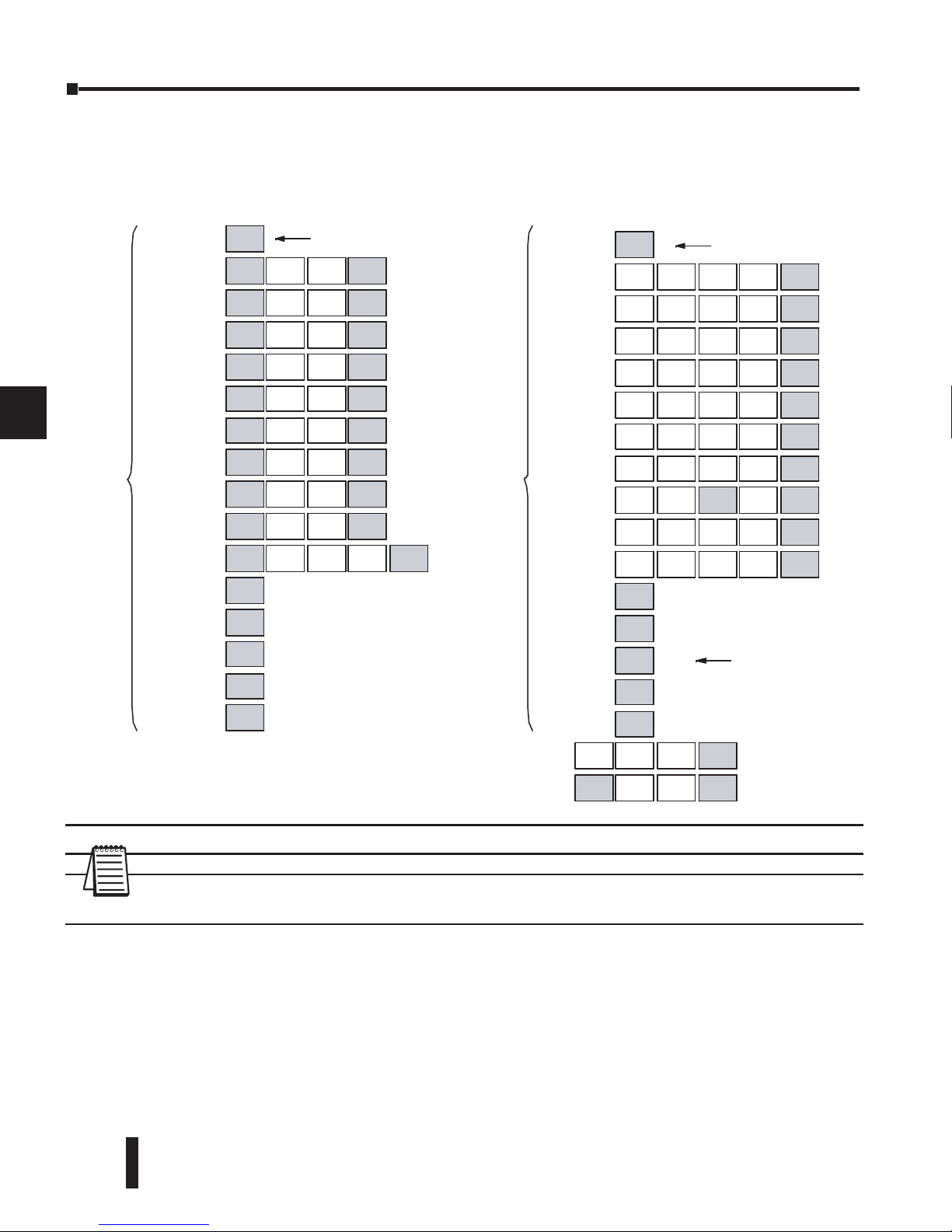
DL06 Micro PLC User Manual, 3rd Edition, Rev. D
6-18
Chapter 6: Drum Instruction Programming
1
2
3
4
5
6
7
8
9
10
11
12
13
14
A
B
C
D
NOTE: You may use the NXT and PREV keys to skip past entries for unused outputs or steps.
NOTE: For ease of operation when using the EDRUM instruction, we recommend using DirectSOFT
over the handheld programmer.
HandheldProgr ammerKeystrokescont’d
unused
(DEF 0000 )
(DEF 0000 )
(DEF 0000 )
(DEF 0000 )
(DEF 0000 )
(DEF 0000 )
(DEF 0000 )
(DEF 0000 )
(DEF 0000 )
(DEF 0000 )
(DEF 0000 )
skipover unused event
(DEF K0000 )
(DEF K0000 )
(DEF K0000 )
(DEF K0000 )
(DEF K0000 )
(DEF K0000 )
(DEF K0000 )
(DEF K0000 )
(DEF K0000 )
(DEF K0000 )
(DEF K0000 )
(DEF K0000 )
(DEF K0000 )
(DEF K0000 )
(DEF K0000 )
(DEF K0000
)
Last rung
6
G
1
16
NEXT
SHFT
ML
SY4
E
NEXT
SHFT
SE
TX1
B
NEXT
SHFT
SE
TX2
C
NEXT
SHFT
2
C
0
A
NEXT
SHFT
2
C
NEXT
1
B
SHFT
SE
T
X
NEXT
0
A
SHFT
SE
T
X
NEXT
5
F
SHFT
SETX3
D
NEXT
SHFT
ML
SY7
H
NEXT
SHFT
2
C
2
C
0
A
NEXT
NEXT
NEXT
NEXT
NEXT
NEXT
NEXT
9
J
8
I
1
B
NEXT
2
C
2
C
8
I
9
J
4
E
NEXT
(DEF 0000 )
(DEF 0000 )
(DEF 0000 )
(DEF 0000 )
(DEF 0000 )
4
E
4
E
7
H
NEXT
5
F
1
B
6
G
9
J
NEXT
9
J
3
D
4
E
3
D
NEXT
4
E
4
E
8
I
6
G
NEXT
9
J
4
E
5
F
NEXT
9
J
3
D
8
I
SHFT
0
A
NEXT
5
F
8
I
6
G
4
E
NEXT
8
I
4
E
4
E
7
H
NEXT
NEXT
NEXT
NEXT
NEXT
NEXT
1
16
HandheldProgr ammerKeystrokescont’d
STR$CNT
G
Y
NEXT
SHFT
MLSY0
A
NEXT
Output
s
Output
Pattern
step 1 pattern = 0000
steps
E
4
Page 47
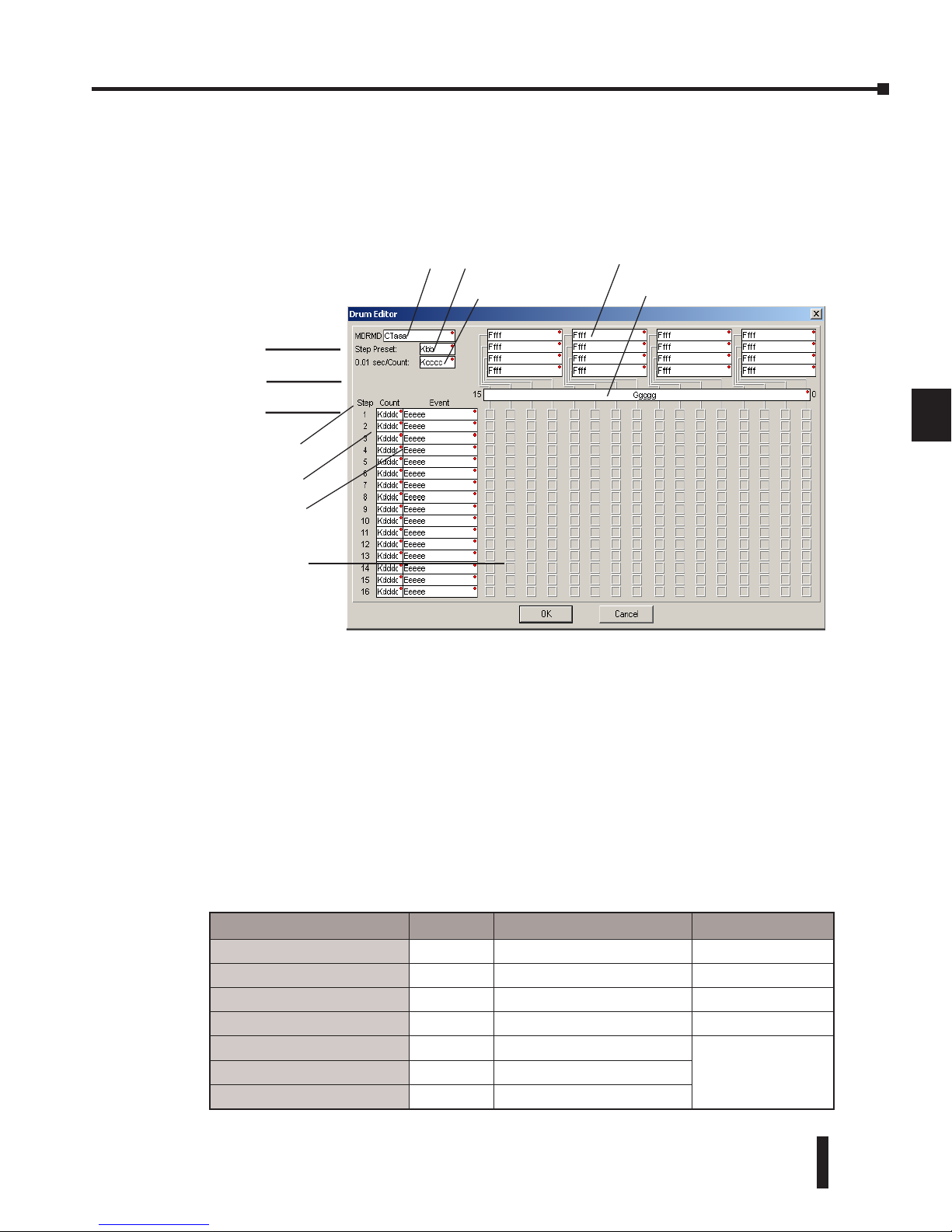
DL06 Micro PLC User Manual, 3rd Edition, Rev. D
6-19
Chapter 6: Drum Instruction Programming
1
2
3
4
5
6
7
8
9
10
11
12
13
14
A
B
C
D
Masked Event Drum with Discrete Outputs (MDRMD)
The Masked Event Drum with Discrete Outputs has all the features of the basic Event Drum
plus final output control for each step. It operates according to the general principles of drum
operation covered in the beginning of this section. Below is the instruction in chart form as
displayed by DirectSOFT.
The Masked Event Drum with Discrete Outputs features sixteen steps and sixteen outputs.
Drum outputs are logically ANDed bit-by-bit with an output mask word for each step. The
Ggggg field specifies the beginning location of the 16 mask words. Step transitions occur on
timed and/or event basis. The jog input also advances the step on each off-to-on transition.
Time is specified in counts per step, and events are specified as discrete contacts. Unused
steps and events can be left blank (this is the default entry). Whenever the Start input is
energized, the drum’s timer is enabled. As long as the event is true for the current step,
the timer runs during that step. When the step count equals the counts per step, the drum
transitions to the next step. This process stops when the last step is complete, or when the
Reset input is energized. The drum enters the preset step chosen upon a CPU program-torun mode transition, and whenever the Reset input is energized.
Drum Parameters Field Data Types Ranges
Counter Number
aaa – 0 – 174
Preset Step
bb K 1 – 16
Timer base
cccc K 0 – 99.99 seconds
Counts per step
dddd K 0 – 9999
Event
eeee X, Y, C, S, T, ST, GX, GY. CT, SP
see memory map
Discrete Outputs
Fffff X, Y, C, GX, GY
Output Mask
Ggggg V
Direct SOFT 5 Display
Step Number
Start
Jog
Counts per Step
Output Pattern
l= Off, L= On
Counter Number
Step Preset
Timebase
Output Mask Word
{
Control
Inputs
Reset
Event per Step
Discrete Output Assignment
Page 48
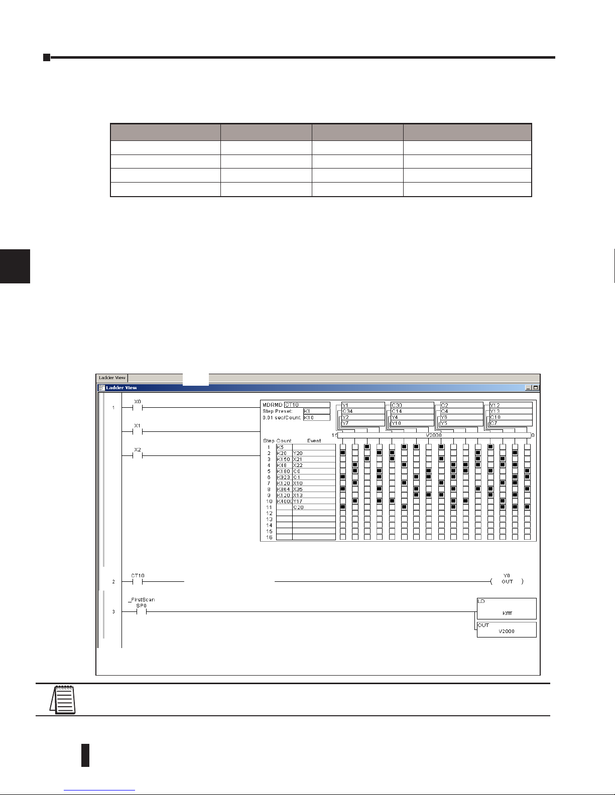
DL06 Micro PLC User Manual, 3rd Edition, Rev. D
6-20
Chapter 6: Drum Instruction Programming
1
2
3
4
5
6
7
8
9
10
11
12
13
14
A
B
C
D
Drum instructions use four counters in the CPU. The ladder program can read the counter
values for the drum’s status. The ladder program may write a new preset step number to
CTA(n+2) at any time. However, the other counters are for monitoring purposes only.
The following ladder program shows the MDRMD instruction in a typical ladder program,
as shown by DirectSOFT. Steps 1 through 11 are used, and all 16 output points are used.
The output mask word is at V2000. The final drum outputs are shown above the mask word
as individual bits. The data bits in V2000 are logically ANDed with the output pattern of the
current step in the drum. If you want all drum outputs to be off after powerup, write zeros
to V2000 on the first scan. Ladder logic may update the output mask at any time to enable
or disable the drum outputs The preset step is step 1. The timebase runs at (K10 x 0.01)=0.1
second per count. Therefore, the duration of step 1 is (5 x 0.1) = 0.5 seconds. Note that step
1 is time-based only (event is left blank). In the last rung, the Drum Complete bit (CT10)
turns on output Y0 upon completion of the last step (step 10). A drum reset also resets CT10.
Counter Number Ranges of (n) Function Counter Bit Function
CTA(n) 0 – 174 Counts in step CT(n) = Drum Complete
CTA( n+1) 1 – 175 Timer value CT(n+1) = (not used)
CTA( n+2) 2 –176 Preset Step CT(n+2) = (not used)
CTA( n+3) 3 –177 Current Step CT(n+1) = (not used)
NOTE: The ladder program must load constants in V2000 through V2012 to cover all mask registers
for the eleven steps used in this drum.
Direct SOFT 5 Display
Start
Reset
Drum Complete
Jog
Set Mask Registers
Page 49
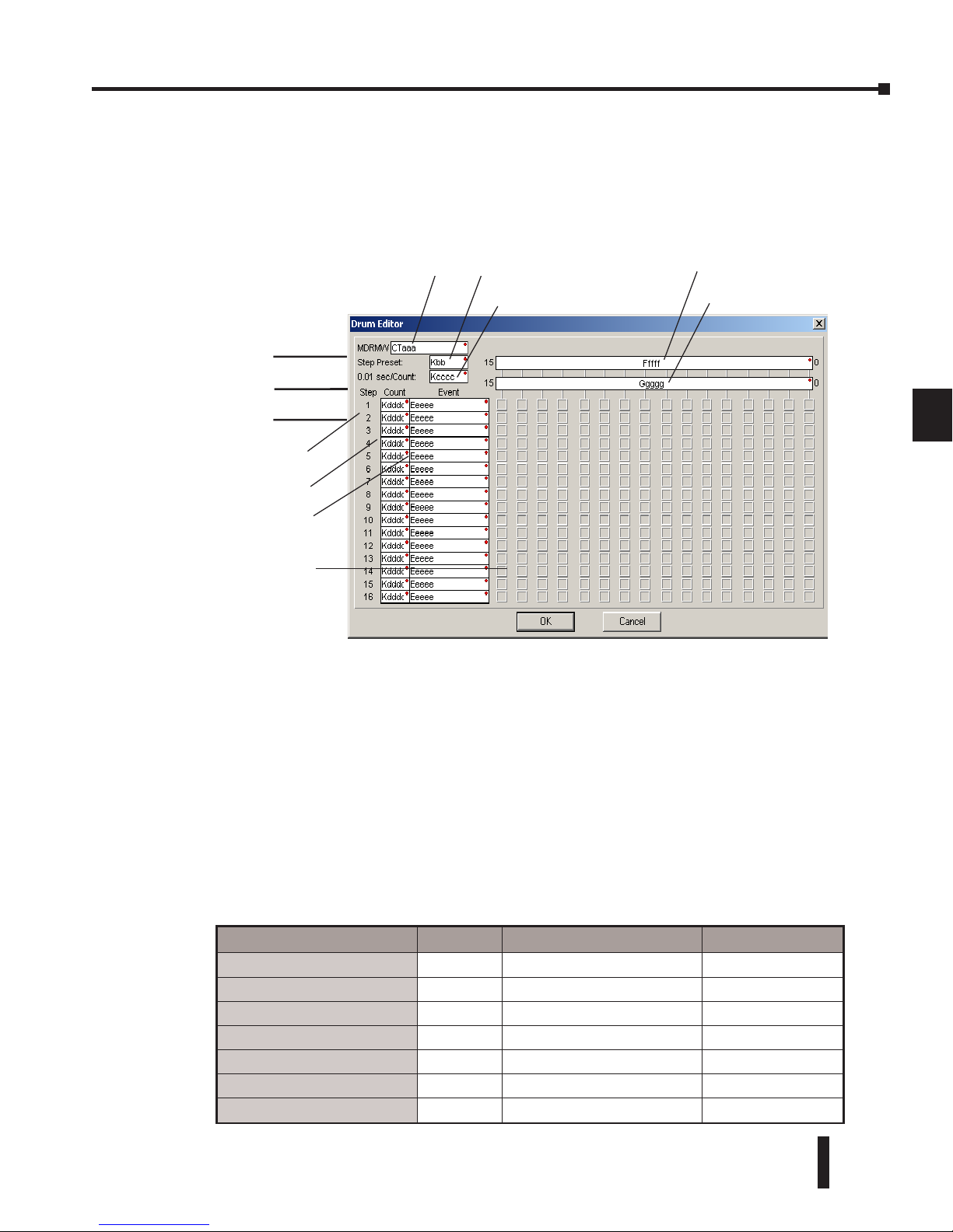
DL06 Micro PLC User Manual, 3rd Edition, Rev. D
6-21
Chapter 6: Drum Instruction Programming
1
2
3
4
5
6
7
8
9
10
11
12
13
14
A
B
C
D
Masked Event Drum with Word Output (MDRMW)
The Masked Event Drum with Word Output features outputs organized as bits of a single
word, rather than discrete points. It operates according to the general principles of drum
operation covered in the beginning of this section. Below is the instruction in chart form as
displayed by DirectSOFT.
The Masked Event Drum with Word Output features sixteen steps and sixteen outputs.
Drum outputs are logically ANDed bit-by-bit with an output mask word for each step. The
Ggggg field specifies the beginning location of the 16 mask words, creating the final output
(Fffff field). Step transitions occur on timed and/or event basis. The jog input also advances
the step on each off-to-on transition. Time is specified in counts per step, and events are
specified as discrete contacts. Unused steps and events can be left blank (this is the default
entry).
Whenever the Start input is energized, the drum’s timer is enabled. As long as the event is
true for the current step, the timer runs during that step. When the step count equals the
counts per step, the drum transitions to the next step. This process stops when the last step is
complete, or when the Reset input is energized. The drum enters the preset step chosen upon
a CPU program-to-run mode transition, and whenever the Reset input is energized.
Drum Parameters Field Data Types Ranges
Counter Number
aaa – 0 – 174
Preset Step
bb K 1 – 16
Timer base
cccc K 0 – 99.99 seconds
Counts per step
dddd K 0 – 9999
Event
eeee X, Y, C, S, T, ST, GX, GY, SP see memory map
Word Output
Fffff V see memory map
Output Mask
Ggggg V see memory map
Direct SOFT 5 Display
Step Number
Start
Jog
Counts per Step
Output Pattern
l= Off, L= On
Counter Number
Step Preset
Timebase
Output Mask Word
{
Control
Inputs
Reset
Event per Step
Word Output Assignment
Page 50
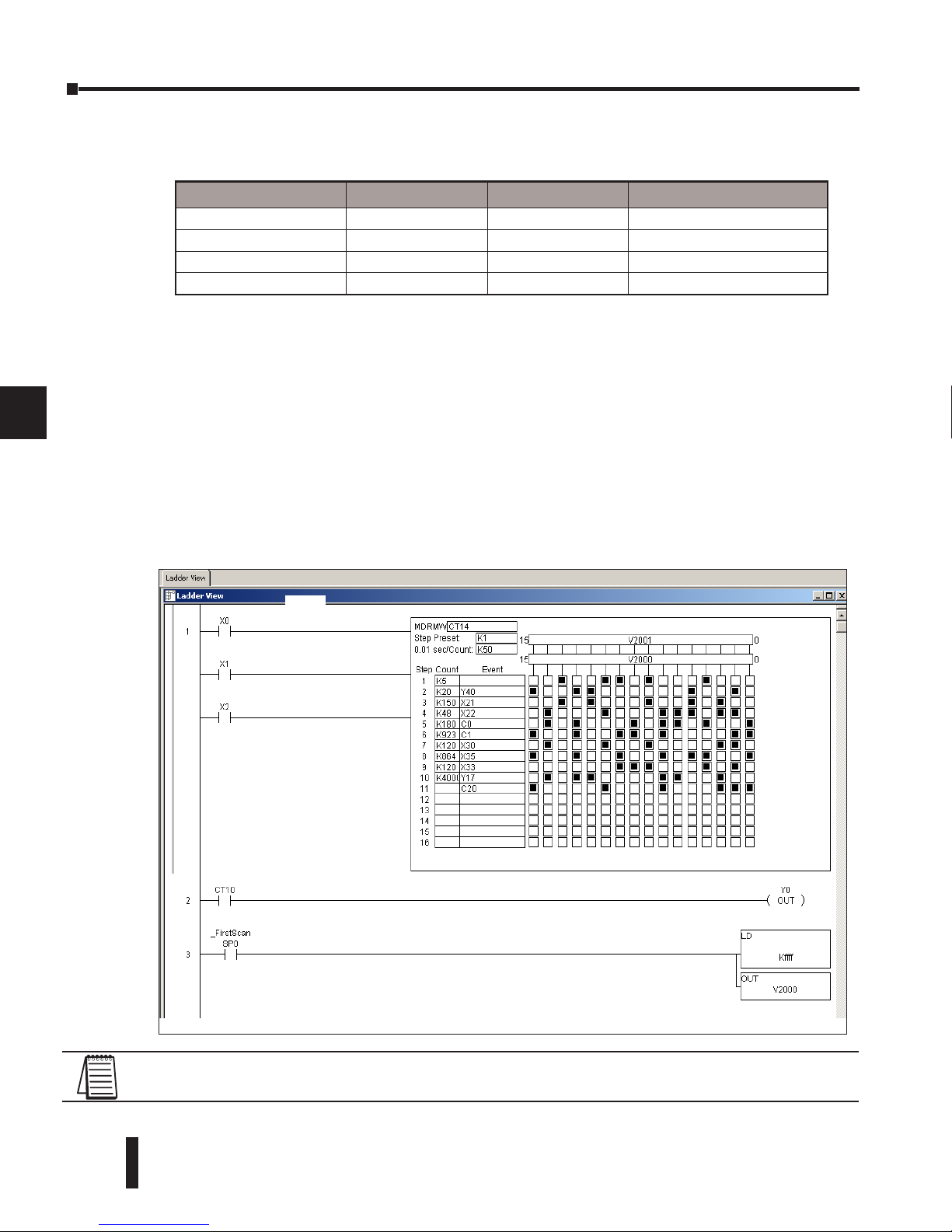
DL06 Micro PLC User Manual, 3rd Edition, Rev. D
6-22
Chapter 6: Drum Instruction Programming
1
2
3
4
5
6
7
8
9
10
11
12
13
14
A
B
C
D
Drum instructions use four counters in the CPU. The ladder program can read the counter
values for the drum’s status. The ladder program may write a new preset step number to
CTA(n+2) at any time. However, the other counters are for monitoring purposes only.
The following ladder program shows the MDRMD instruction in a typical ladder program,
as shown by DirectSOFT. Steps 1 through 11 are used, and all sixteen output points are used.
The output mask word is at V2000. The final drum outputs are shown above the mask word
as a word at V2001. The data bits in V2000 are logically ANDed with the output pattern of
the current step in the drum, generating the contents of V2001. If you want all drum outputs
to be off after powerup, write zeros to V2000 on the first scan. Ladder logic may update the
output mask at any time to enable or disable the drum outputs. The preset step is step 1. The
timebase runs at (K50 x 0.01)=0.5 seconds per count. Therefore, the duration of step 1 is (5
x 0.5) = 2.5 seconds. Note that step 1 is time-based only (event is left blank). In the last rung,
the Drum Complete bit (CT14) turns on output Y0 upon completion of the last step (step
10). A drum reset also resets CT14.
Counter Number Ranges of (n) Function Counter Bit Function
CTA(n) 0 – 174 Counts in step CT(n) = Drum Complete
CTA( n+1) 1 – 175 Timer value CT(n+1) = (not used)
CTA( n+2) 2 –176 Preset Step CT(n+2) = (not used)
CTA( n+3) 3 –177 Current Step CT(n+1) = (not used)
NOTE: The ladder program must load constants in V2000 through V2012 to cover all mask registers
for the eleven steps used in this drum.
Direct SOFT 5 Display
Start
Reset
Drum Complete
Jog
Set Mask Registers
Page 51

RLL
PLUS
Stage
PRogRamming
7
7
7
Chapter
Chapter
Chapter
RLL
PLUS
Stage
PRogRamming
7
7
7
Chapter
Chapter
Chapter
In This Chapter...
Introduction to Stage Programming ................................................ 7–2
Learning to Draw State Transition Diagrams .................................... 7–3
Using the Stage Jump Instruction for State Transitions ..................... 7–7
Stage Program Example: Toggle On/Off Lamp Controller ................ 7–8
Four Steps to Writing a Stage Program ............................................ 7–9
Stage Program Example: A Garage Door Opener ........................... 7–10
Stage Program Design Considerations ........................................... 7–15
Parallel Processing Concepts .......................................................... 7–19
RLL
PLUS
(Stage) Instructions ............................................................ 7–21
Questions and Answers about Stage Programming ........................ 7–27
Page 52
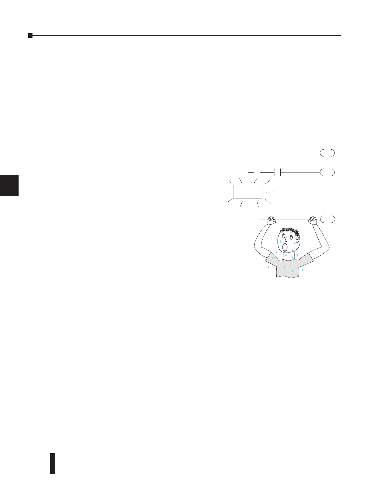
DL06 Micro PLC User Manual, 3rd Edition, Rev. D
7-2
Chapter 7: RLL
PLUS
Stage Programming
1
2
3
4
5
6
7
8
9
10
11
12
13
14
A
B
C
D
Introduction to Stage Programming
Stage Programming provides a way to organize and program complex applications with
relative ease, when compared to purely relay ladder logic (RLL) solutions. Stage programming
does not replace or negate the use of traditional boolean ladder programming. This is
why Stage Programming is also called RLL
plus
You won’t have to discard any training or
experience you already have. Stage programming simply allows you to divide and organize an
RLL program into groups of ladder instructions called stages. This allows quicker and more
intuitive ladder program development than traditional RLL alone provides.
It’s easy to see that these inefficiencies consume a lot of additional time, and time is money.
Stage programming overcomes these obstacles! We believe a few moments of studying the stage
concept is one of the greatest investments in programming speed and efficiency a PLC
programmer can make!
So, we encourage you to study stage programming and add it to your toolbox of
programming techniques. This chapter is designed as a self-paced tutorial on stage
programming. For best results:
• Start at the beginning and do not skip over any sections.
• Study each stage programming concept by working through each example. The examples build
progressively on each other.
• Read the Stage Questions and Answers at the end of the chapter for a quick review.
1
2
3
4
5
6
7
8
9
10
11
12
13
14
a
B
C
D
STAGE!
Y2
X3
OUT
X0
RST
C0
X4
SET
Y0
C1
Overcoming “Stage Fright”
Many PLC programmers in the industry
have become comfortable using RLL for
every PLC program they write, but often
remain skeptical or even fearful of learning
new techniques such as stage programming.
While RLL is great at solving boolean logic
relationships, it has disadvantages as well:
• Large programs can become almost
unmanageable, because of a lack of structure.
• When a process gets stuck, it is difficult to
find the rung where the error occurred.
• Programs become difficult to modify later,
because they do not intuitively resemble the
application problem they are solving.
Page 53
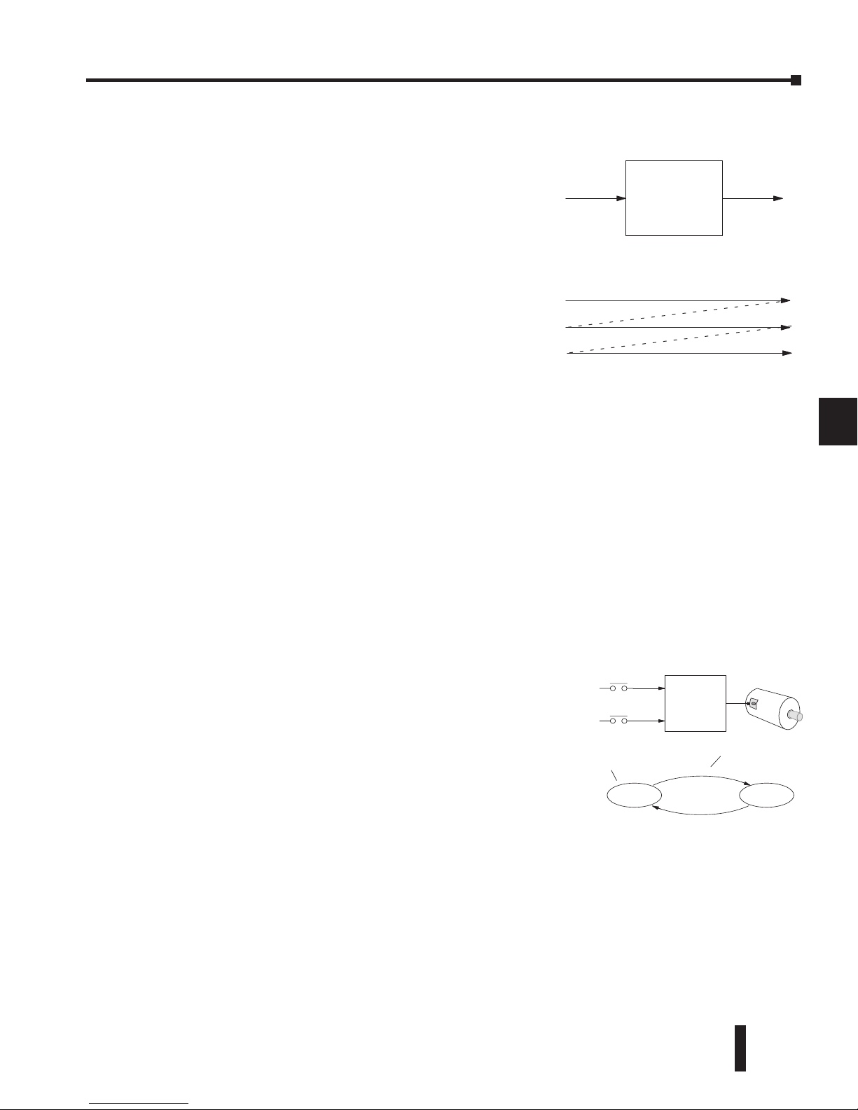
DL06 Micro PLC User Manual, 3rd Edition, Rev. D
7-3
Chapter 7: RLL
PLUS
Stage Programming
1
2
3
4
5
6
7
8
9
10
11
12
13
14
A
B
C
D
Learning to Draw State Transition Diagrams
Introduction to Process States
Those familiar with ladder program execution know that
the CPU must scan the ladder program repeatedly, over
and over. Its three basic steps are:
1. Read the inputs
2. Execute the ladder program
3. Write the outputs
The benefit is that a change at the inputs can affect the
outputs in just a few milliseconds.
Most manufacturing processes consist of a series of
activities or conditions, each lasting for several seconds, minutes, or even hours. We might
call these process states, which are either active or inactive at any particular time. A challenge
for RLL programs is that a particular input event may last for just a brief instant. We typically
create latching relays in RLL to preserve the input event in order to maintain a process state
for the required duration.
We can organize and divide ladder logic into sections called stages, representing process
states. But before we describe stages in detail, we will reveal the secret to understanding stage
programming: state transition diagrams.
The Need for State Diagrams
Sometimes we need to forget about the scan nature of PLCs, and focus our thinking toward
the states of the process we need to identify. Clear thinking and concise analysis of an
application gives us the best chance at writing efficient, bug-free programs. State diagrams are
just a tool to help us draw a picture of our process! You’ll discover that if we can get the picture
right, our program will also be right!
A 2–State Process
Consider the simple process shown to the right, which controls
an industrial motor. We will use a green momentary SPST
pushbutton to turn the motor on, and a red one to turn it off.
The machine operator will press the appropriate pushbutton for
just a second or so. The two states of our process are ON and
OFF.
The next step is to draw a state transition diagram, as shown
to the right. It shows the two states OFF and ON, with two
transition lines in-between. When the event X0 is true, we transition from OFF to ON.
When X1 is true, we transition from ON to OFF.
If you’re following along, you are very close to grasping the concept and the problem-solving
power of state transition diagrams. The output of our controller is Y0, which is true any time
we are in the ON state. In a boolean sense, Y0=ON state.
Next, we will implement the state diagram first as RLL, then as a stage program. This will
help you see the relationship between the two methods in problem solving.
1
2
3
4
5
6
7
8
9
10
11
12
13
14
a
B
C
D
Ladder
Program
Inputs Outputs
1) Read Execute Write
Execute
Write
(Etc.....)
2) Read
3) Read
Ladder
Program
Inputs Outputs
OFF
Motor
X0
X1
Y0
OFF ON
X0
X1
Output equation: Y0 = On
State
Transition condition
ON
Page 54
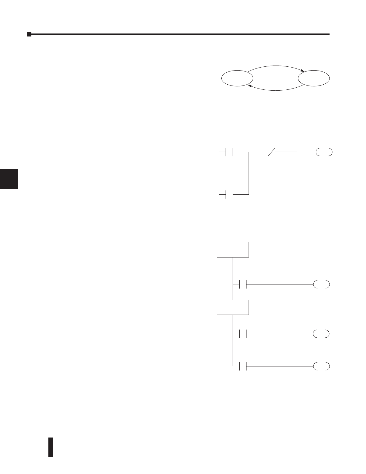
DL06 Micro PLC User Manual, 3rd Edition, Rev. D
7-4
Chapter 7: RLL
PLUS
Stage Programming
1
2
3
4
5
6
7
8
9
10
11
12
13
14
A
B
C
D
1
2
3
4
5
6
7
8
9
10
11
12
13
14
a
B
C
D
OFF ON
X1
X0
Output equation Y0 = ON
X1X0
OUT
Y0
Set
Reset
Output
Latch
Y0
S1
X0
JMP
SG
S0
S0
X1
JMP
SG
S1
OUT
Y0
OFF State
ON State
Output
Transition
Transition
SP1
Always On
The state transition diagram to the right is a picture
of the solution we need to create. The beauty of it is
this: it expresses the problem independently of the
programming language we may use to realize it. In
other words, by drawing the diagram we have already
solved the control problem!
First, we’ll translate the state diagram to traditional
RLL. Then, we’ll show how easy it is to translate the
diagram into a stage programming solution.
RLL Equivalent
The RLL solution is shown to the right. Output
control relay, Y0, has a dual purpose. It turns the
motor on and off and acts as a latching relay. When
the On pushbutton (X0) is pressed, output coil
Y0 turns on and the Y0 contact on the second row
latches itself on. So, X0 turns on the motor output
Y0 which now has power flow and sets the latch Y0.
It will remain on after the X0 contact opens.
When the Off pushbutton (X1) is pressed, it opens
the normally-closed X1 contact, which turns off
moter output Y0 and also resets the latch.
Stage Equivalent
The stage program solution is shown to the right.
The two inline stage boxes S0 and S1 correspond
to the two states OFF and ON. The ladder rung(s)
below each stage box belong to each respective stage.
This means that the PLC only has to scan those
rungs when the corresponding stage is active!
For now, let’s assume we begin in the OFF State, so
stage S0 is active. When the On pushbutton (X0)
is pressed, a stage transition occurs. The JMP S1
instruction executes, which simply turns off the Stage
bit S0 and turns on Stage bit S1. So on the next PLC
scan, the CPU will not execute Stage S0, but will
execute stage S1!
In the On State (Stage S1), we want the motor to
always be on. The special relay contact SP1 is defined
as always on, so Y0 turns the motor on.
When the Off pushbutton (X1) is pressed, a transition back to the Off State occurs. The JMP
S0 instruction executes, which simply turns off the Stage bit S1 and turns on Stage bit S0. On
the next PLC scan, the CPU will not execute Stage S1, so the motor output Y0 will turn off.
The Off state (Stage 0) will be ready for the next cycle.
Page 55
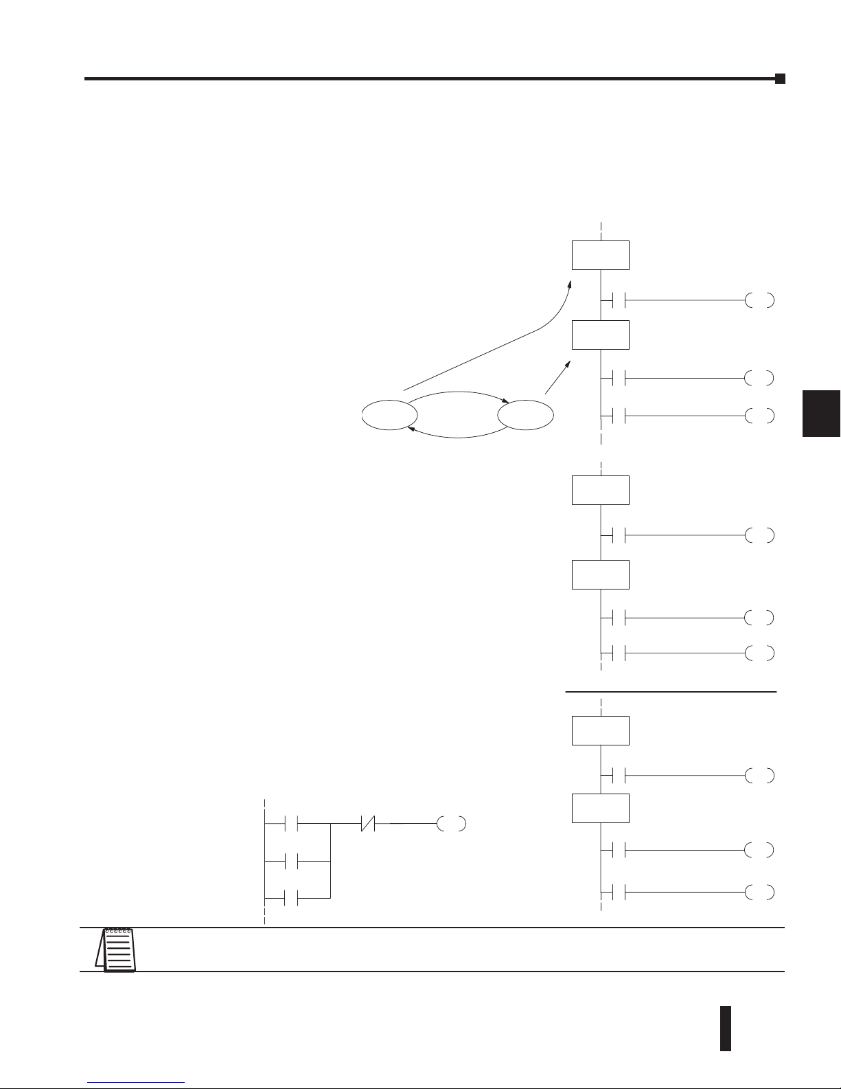
DL06 Micro PLC User Manual, 3rd Edition, Rev. D
7-5
Chapter 7: RLL
PLUS
Stage Programming
1
2
3
4
5
6
7
8
9
10
11
12
13
14
A
B
C
D
Let’s Compare
Right now, you may be thinking, “I don’t see the big advantage to Stage Programming ...
in fact, the stage program is longer than the plain RLL program.” Well, now is the time to
exercise a bit of faith. As control problems grow in complexity, stage programming quickly
out-performs RLL in simplicity, program size, etc.
NOTE: If the ISG is within the retentive range for stages, the ISG will remain in the state it was in
before power down and will NOT turn itself on during the first scan.
1
2
3
4
5
6
7
8
9
10
11
12
13
14
a
B
C
D
S1
X0
JMP
SG
S0
S0
X1
JMP
SG
S1
OUT
Y0
OFF State
ON State
SP1
OFF ON
S1
X0
JMP
ISG
S0
S0
X1
JMP
SG
S1
OUT
Y0
Initial Stage
SP1
S1
X0
JMP
SG
S0
S0
X1
JMP
ISG
S1
OUT
Y0
Initial Stage
SP1
X1X0
OUT
Y0
First Scan
Powerup in OFF State
Powerup in ON State
Powerup in ON State
SP0
Y0
X0
X1
For example, consider the diagram below. Notice how
easy it is to correlate the OFF and ON states of the state
transition diagram below to the stage program at the right.
Now, we challenge anyone to
easily identify the same states
in the RLL program on the
previous page!
Assume that we want to always begin in the Off state
(motor off), which is how the RLL program works. The
Initial Stage (ISG) is defined to be active at powerup.
In the modified program to the right, we have changed
stage S0 to the ISG type. This ensures the PLC will scan
contact X0 after powerup, because Stage S0 is active.
After powerup, an Initial Stage (ISG) works just like any
other stage!
We can change both programs so that the motor is ON at
powerup. In the RLL below, we must add a first scan relay
SP0, latching Y0 on. In the stage example to the right, we
simply make Stage S1 an initial stage (ISG) instead of S0.
Initial Stages
At powerup and Program-toRun Mode transitions, the
PLC always begins with all
normal stages (SG) off. So, the stage programs shown so far
have actually had no way to get started (because rungs are
not scanned unless their stage is active).
Page 56
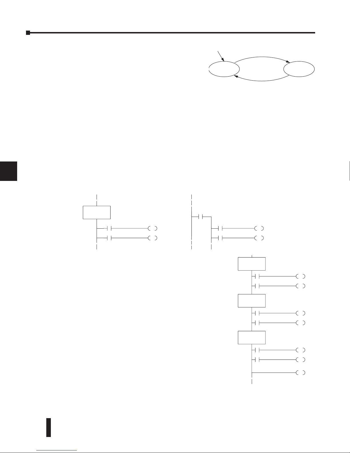
DL06 Micro PLC User Manual, 3rd Edition, Rev. D
7-6
Chapter 7: RLL
PLUS
Stage Programming
1
2
3
4
5
6
7
8
9
10
11
12
13
14
A
B
C
D
We can mark our desired powerup state as shown to the right, which helps us remember
to use the appropriate Initial Stages when creating a
stage program. It is permissible to have as many initial
stages as the process requires.
What Stage Bits Do
You may recall that a stage is just a section of ladder program which is either active or inactive
at a given moment. All stage bits (S0 to 1777) reside in the PLC’s image register as individual
status bits. Each stage bit is either a boolean 0 or 1 at any time.
Program execution always reads ladder rungs from top to bottom, and from left to right.
The drawing below shows the effect of stage bit status. The ladder rungs below the stage
instruction continuing until the next stage instruction or the end of program belong to stage
0. Its equivalent operation is shown on the right. When S0 is true, the two rungs have power
flow.
• If Stage bit S0 = 0, its ladder rungs are not scanned (executed).
• If Stage bit S0 = 1, its ladder rungs are scanned (executed).
1
2
3
4
5
6
7
8
9
10
11
12
13
14
a
B
C
D
OFF ON
X1
X0
SG
S0
Actual Program Appearance Functionally Equivalent Ladder
S0
(includes all rungs in stage)
SG
S0
SG
S1
SG
S2
END
Stage Instruction Characteristics
The inline stage boxes on the left power rail divide the
ladder program rungs into stages. Some stage rules are:
• Execution – Only logic in active stages are executed on any
scan.
• Transitions – Stage transition instructions take effect on the
next occurrence of the stages involved.
• Octal numbering – Stages are numbered in octal, like I/O
points, etc. So “S8” is not valid.
• Total Stages – The DL06 offers up to 1024 stages
(S0 to 1777 in octal).
• No duplicates – Each stage number is unique and can be used
just once.
• Any order – You can skip numbers and sequence the stage
numbers in any order.
• Last Stage – The last stage in the ladder program includes all
rungs from its stage box until the end coil.
Page 57
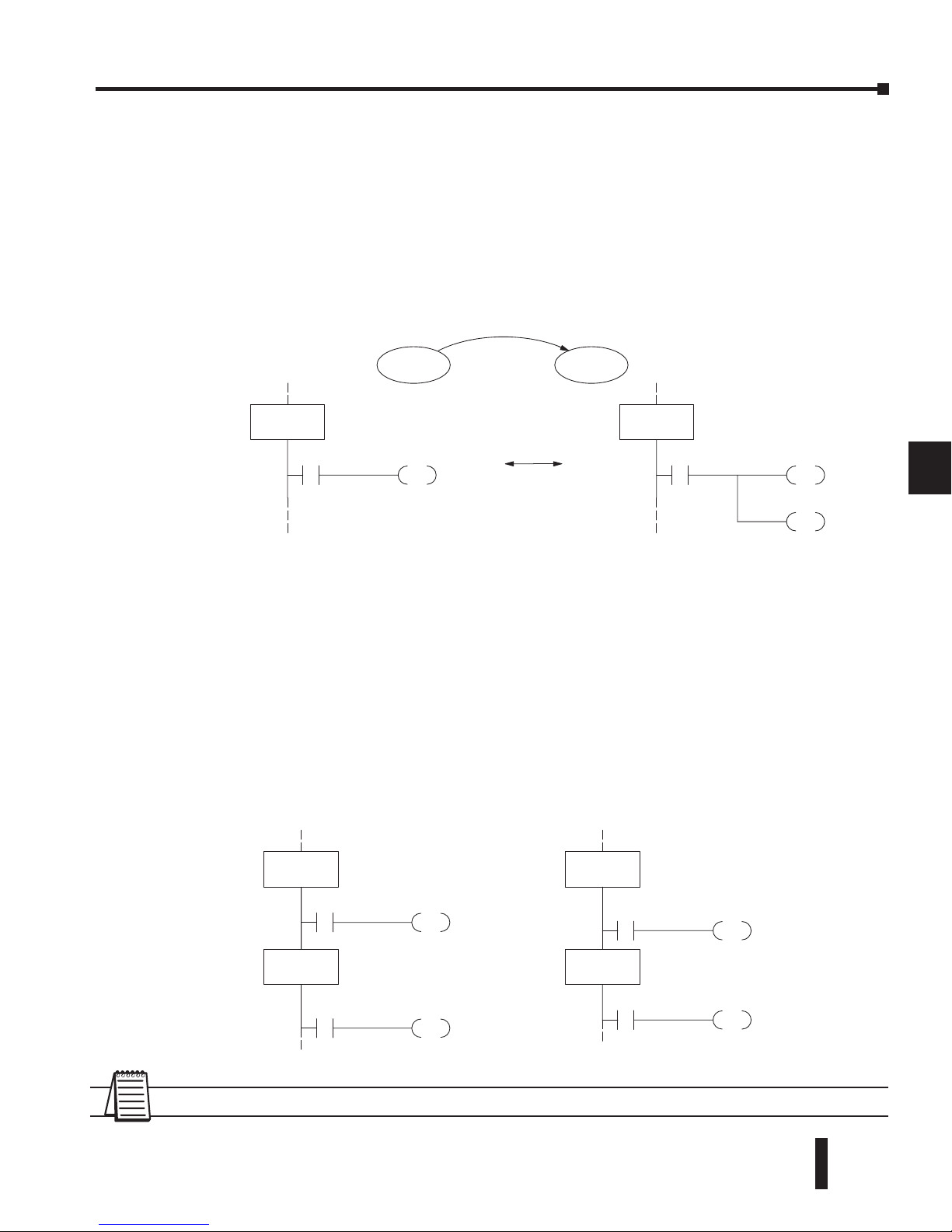
DL06 Micro PLC User Manual, 3rd Edition, Rev. D
7-7
Chapter 7: RLL
PLUS
Stage Programming
1
2
3
4
5
6
7
8
9
10
11
12
13
14
A
B
C
D
Using the Stage Jump Instruction for State Transitions
Stage Jump, Set, and Reset Instructions
The Stage JMP instruction we have used deactivates the stage in which the instruction occurs,
while activating the stage in the JMP instruction. Refer to the state transition shown below.
When contact X0 energizes, the state transition from S0 to S1 occurs. The two stage examples
shown below are equivalent. So, the Stage Jump instruction is equal to a Stage Reset of the
current stage, plus a Stage Set instruction for the stage to which we want to transition.
Please Read Carefully – The jump instruction is easily misunderstood. The “jump” does not
occur immediately like a GOTO or GOSUB program control instruction when executed.
Here’s how it works:
• The jump instruction resets the stage bit of the stage in which it occurs. All rungs in the stage still
finish executing during the current scan, even if there are other rungs in the stage below the jump
instruction!
• The reset will be in effect on the following scan, so the stage that executed the jump instruction
previously will be inactive and bypassed.
• The stage bit of the stage named in the Jump instruction will be set immediately, so the stage will
be executed on its next occurrence. In the left program shown below, stage S1 executes during the
same scan as the JMP S1 occurs in S0. In the example on the right, Stage S1 executes on the next
scan after the JMP S1 executes, because stage S1 is located above stage S0.
NOTE: Assume we start with Stage 0 active and Stage 1 inactive for both examples.
1
2
3
4
5
6
7
8
9
10
11
12
13
14
a
B
C
D
S1
X0
JMP
SG
S0
Equivalent
S0
X0
RST
SG
S0
S1
SET
S0 S1
X0
S1
X0
JMP
SG
S0
Y0
S1
OUT
SG
S1
S1
X0
JMP
SG
S0
Y0
S1
OUT
SG
S1
Executes on same
scan as Jmp
Executes on next
scan after Jmp
Page 58
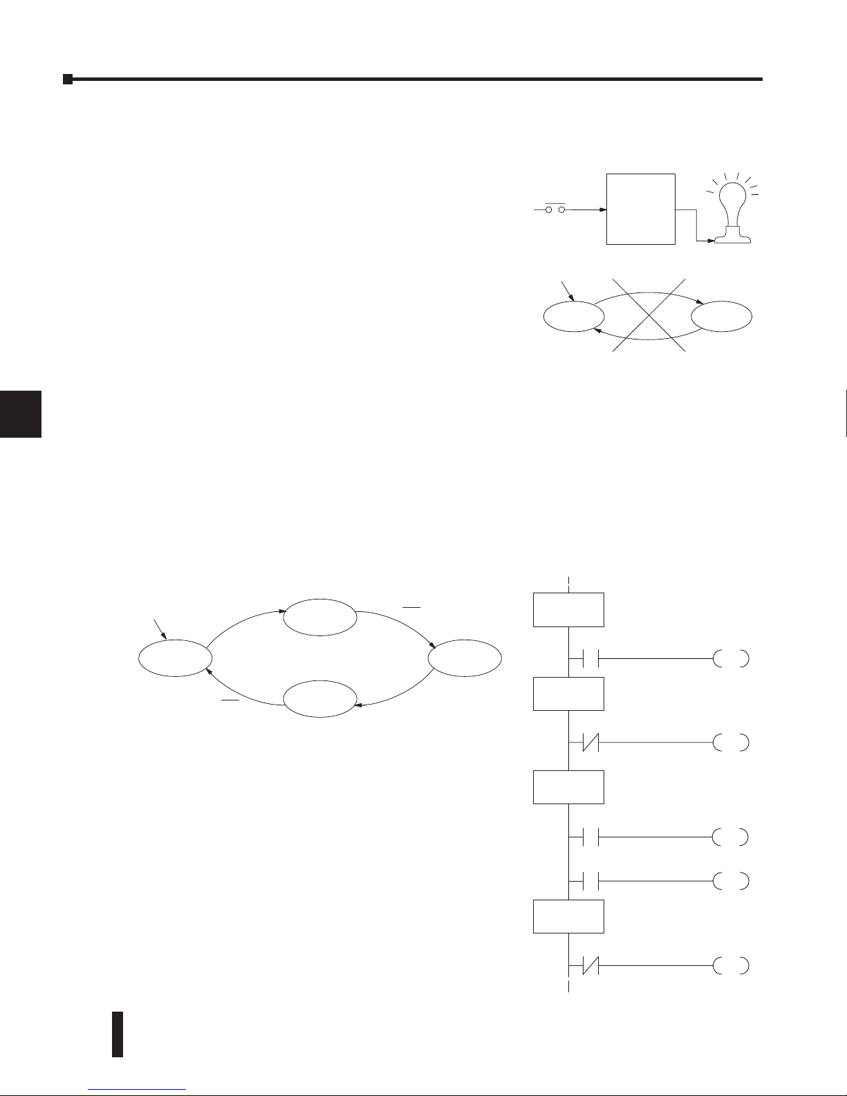
DL06 Micro PLC User Manual, 3rd Edition, Rev. D
7-8
Chapter 7: RLL
PLUS
Stage Programming
1
2
3
4
5
6
7
8
9
10
11
12
13
14
A
B
C
D
Stage Program Example: Toggle On/Off Lamp Controller
A 4–State Process
In the process shown to the right, we use an ordinary
momentary pushbutton to control a light bulb. The
ladder program will latch the switch input, so that we
will push and release to turn on the light, push and
release again to turn it off (sometimes called toggle
function). Sure, we could just buy a mechanical switch
with the alternate on/off action built in... However, this
example is educational and also fun! Next we draw the
state transition diagram.
A typical first approach is to use X0 for both transitions
(like the example shown to the right). However, this is incorrect (please keep reading).
Note that this example differs from the motor example, because now we have just one
pushbutton. When we press the pushbutton, both transition conditions are met. We would
just transition around the state diagram at top speed. If implemented in Stage, this solution
would flash the light on or off each scan (obviously undesirable)!
The solution is to make the push and the release of the pushbutton separate events. Refer to
the new state transition diagram below. At powerup we enter the OFF state. When switch X0
is pressed, we enter the Press-ON state. When it is released, we enter the ON state. Note that
X0 with the bar above it denotes X0 NOT.
When in the ON state, another push and release
cycle similarly takes us back to the OFF state. Now
we have two unique states (OFF and ON) used
when the pushbutton is released, which is what was
required to solve the control problem.
The equivalent stage program is shown to the right. The
desired powerup state is OFF, so we make S0 an initial
stage (ISG). In the ON state, we add special relay contact
SP1, which is always on.
Note that even as our programs grow more complex, it is
still easy to correlate the state transition diagram with the
stage program!
1
2
3
4
5
6
7
8
9
10
11
12
13
14
a
B
C
D
Ladder
Program
Inputs Outputs
Toggle
X0 Y0
OFF ON
X0
X0
Output equation: Y0 = ON
Powerup
S1
X0
JMP
ISG
S0
S2
JMP
SG
S1
OUT
Y0
OFF State
SP1
S3
X0
JMP
SG
S2
SG
S3
X0
S0
JMP
X0
Push–On State
ON State
Push–Off State
Output
X0
Push–ON
ON
Push–OFF
OFF
Powerup
X0
X0
X0
Page 59

DL06 Micro PLC User Manual, 3rd Edition, Rev. D
7-9
Chapter 7: RLL
PLUS
Stage Programming
1
2
3
4
5
6
7
8
9
10
11
12
13
14
A
B
C
D
Four Steps to Writing a Stage Program
By now, you’ve probably noticed that we follow the same steps to solve each example
problem. The steps will probably come to you automatically if you work through all the
examples in this chapter. It’s helpful to have a checklist to guide us through the problem
solving. The following steps summarize the stage program design procedure:
1. Write a Word Description of the application.
Describe all functions of the process in your own words. Start by listing what happens
first, then next, etc. If you find there are too many things happening at once, try dividing
the problem into more than one process. Remember, you can still have the processes
communicate with each other to coordinate their overall activity.
2. Draw the Block Diagram.
Inputs represent all the information the process needs for decisions, and outputs connect to
all devices controlled by the process.
• Make lists of inputs and outputs for the process.
• Assign I/O point numbers (X and Y) to physical inputs and outputs.
3. Draw the State Transition Diagram.
The state transition diagram describes the central function of the block diagram, reading
inputs and generating outputs.
• Identify and name the states of the process.
• Identify the event(s) required for each transition between states.
• Ensure the process has a way to re-start itself, or is cyclical.
• Choose the powerup state for your process.
• Write the output equations.
4. Write the Stage Program.
Translate the state transition diagram into a stage program.
• Make each state a stage. Remember to number stages in octal. Up to 1024 total stages are available
in the DL06, numbered 0 to 1777 in octal.
• Put transition logic inside the stage which originates each transition (the stage each arrow points
away from).
• Use an initial stage (ISG) for any states that must be active at powerup.
• Place the outputs or actions in the appropriate stages.
You’ll notice that Steps 1 through 3 just prepare us to write the stage program in Step 4.
However, the program virtually writes itself because of the preparation beforehand. Soon
you’ll be able to start with a word description of an application and create a stage program in
one easy session!
1
2
3
4
5
6
7
8
9
10
11
12
13
14
a
B
C
D
Page 60
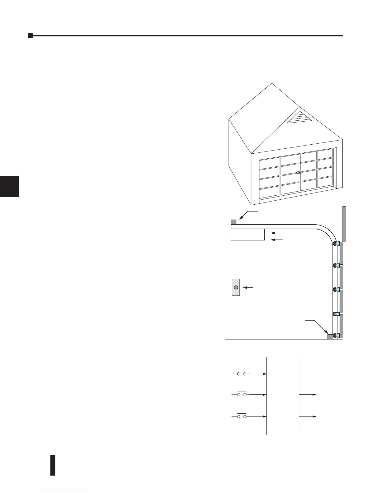
DL06 Micro PLC User Manual, 3rd Edition, Rev. D
7-10
Chapter 7: RLL
PLUS
Stage Programming
1
2
3
4
5
6
7
8
9
10
11
12
13
14
A
B
C
D
Stage Program Example: A Garage Door Opener
Garage Door Opener Example
1
2
3
4
5
6
7
8
9
10
11
12
13
14
a
B
C
D
Down limit switch
Raise
Lower
Door
Command
Up limit switch
Motor
Ladder
Program
Inputs Outputs
Toggle
X0
Y1
To motor:
Raise
Y2
Lower
Up limit
X1
Down limit
X2
In this next stage programming example, we’ll
create a garage door opener controller. Hopefully,
most readers are familiar with this application, and
we can have fun, too!
The first step we must take is to describe how the
door opener works. We will start by achieving the
basic operation, waiting to add extra features later.
Stage programs are very easy to modify.
Our garage door controller has a motor which raises
or lowers the door on command. The garage owner
pushes and releases a momentary pushbutton once
to raise the door. After the door is up, another
push-release cycle will lower the door.
In order to identify the inputs and outputs of the
system, it’s sometimes helpful to sketch its main
components, as shown in the door side view to the
right. The door has an up limit and a down limit
switch. Each limit switch closes only when the door
has reach the end of travel in the corresponding
direction. In the middle of travel, neither limit
switch is closed.
The motor has two command inputs: raise and
lower. When neither input is active, the motor
is stopped. The door command is just a simple
pushbutton. Whether wall-mounted as shown, or
a radio-remote control, all door control commands
logical OR together as one pair of switch contacts.
Draw the Block Diagram
The block diagram of the controller is shown to
the right. Input X0 is from the pushbutton door
control. Input X1 energizes when the door reaches
the full up position. Input X2 energizes when the
door reaches the full down position. When the door
is positioned between fully up or down, both limit
switches are open.
The controller has two outputs to drive the motor.
Y1 is the up (raise the door) command, and Y2 is
the down (lower the door) command.
Page 61
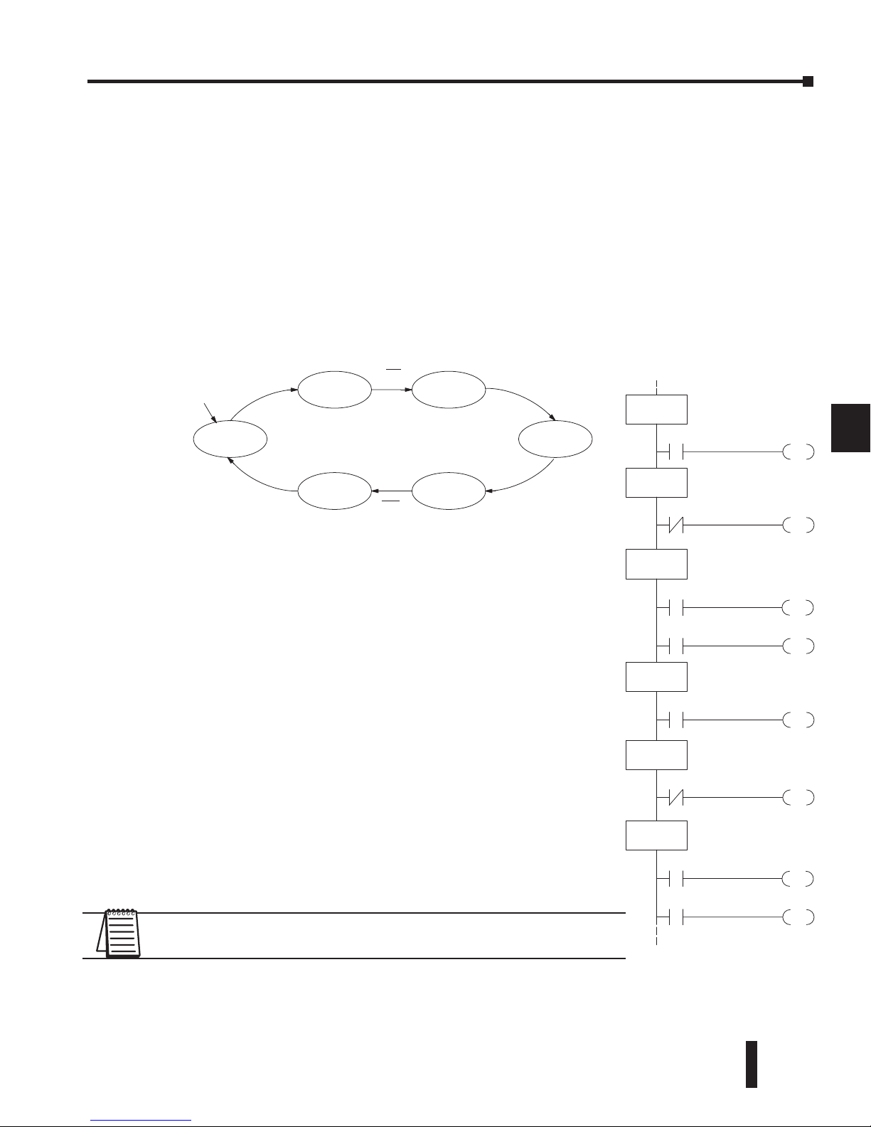
DL06 Micro PLC User Manual, 3rd Edition, Rev. D
7-11
Chapter 7: RLL
PLUS
Stage Programming
1
2
3
4
5
6
7
8
9
10
11
12
13
14
A
B
C
D
Draw the State Diagram
Now we are ready to draw the state transition diagram. Like the previous light bulb controller
example, this application also has just one switch for the command input. Refer to the figure
below.
• When the door is down (DOWN state), nothing happens until X0 energizes. Its push and release
brings us to the RAISE state, where output Y1 turns on and causes the motor to raise the door.
• We transition to the UP state when the up limit switch (X1) energizes, and turns off the motor.
• Then nothing happens until another X0 press-release cycle occurs. That takes us to the LOWER
state, turning on output Y2 to command the motor to lower the door. We transition back to the
DOWN state when the down limit switch (X2) energizes.
The equivalent stage program is shown to the right. For now, we
will assume the door is down at powerup, so the desired powerup
state is DOWN. We make S0 an initial stage (ISG). Stage S0
remains active until the door control pushbutton activates. Then
we transition (JMP) to Push-UP stage, S1.
A push-release cycle of the pushbutton takes us through stage
S1 to the RAISE stage, S2. We use the always-on contact SP1 to
energize the motor’s raise command, Y1. When the door reaches
the fully-raised position, the up limit switch X1 activates. This
takes us to the UP Stage S3, where we wait until another door
control command occurs.
In the UP Stage S3, a push-release cycle of the pushbutton
will take us to the LOWER Stage S5, where we activate Y2 to
command the motor to lower the door. This continues until the
door reaches the down limit switch, X2. When X2 closes, we
transition from Stage S5 to the DOWN stage S0, where we began.
NOTE: The only special thing about an initial stage (ISG) is that it is
automatically active at powerup. Afterwards, it is just like any other.
1
2
3
4
5
6
7
8
9
10
11
12
13
14
a
B
C
D
X0
Push–UP
UP
Push–DOWN
DOWN
X0
LOWER
RAISE
X0
X1
X0
X2
Output equations: Y1 = Raise Y2 = Lower
Powerup
S1
X0
JMP
ISG
S0
S2
JMP
SG
S1
OUT
Y1
DOWN State
SP1
S3
X1
JMP
SG
S2
SG
S3
X0
S4
JMP
X0
Push–UP State
RAISE State
UP State
S5
JMP
SG
S4
X0
Push–DOWN State
OUT
Y2
SP1
S0
X2
JMP
SG
S5
LOWER State
Page 62
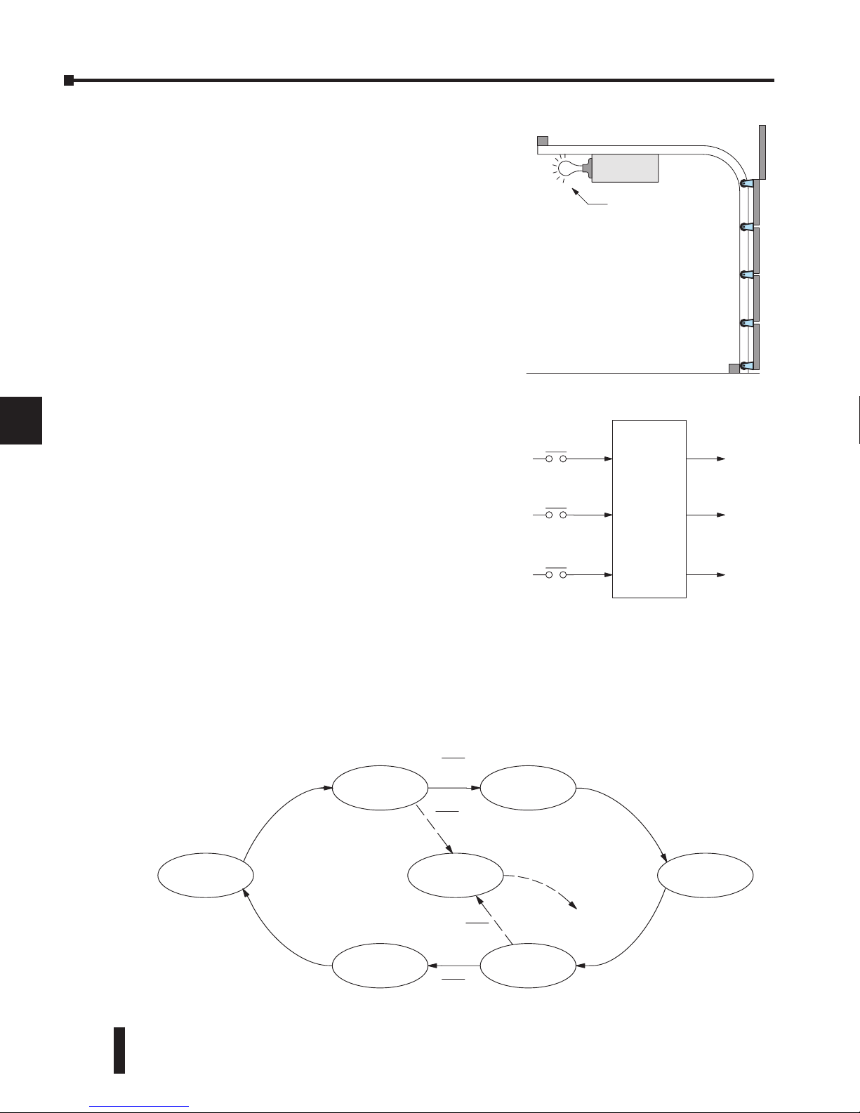
DL06 Micro PLC User Manual, 3rd Edition, Rev. D
7-12
Chapter 7: RLL
PLUS
Stage Programming
1
2
3
4
5
6
7
8
9
10
11
12
13
14
A
B
C
D
We can think of the Light state as a parallel process to the raise and lower state. The paths
to the Light state are not a transition (Stage JMP), but a State Set command. In the logic of
the Light stage, we will place a three-minute timer. When it expires, timer bit T0 turns on
and resets the Light stage. The path out of the Light stage goes nowhere, indicating the Light
stage just becomes inactive, and the light goes out!
1
2
3
4
5
6
7
8
9
10
11
12
13
14
a
B
C
D
Safety light
Inputs Outputs
Toggle
X0 Y1
Raise
Y2
Lower
Up limit
X1
Down limit
X2 Y3
Light
X0
Push–UP
UP
Push–DOWN
DOWN
X0
LOWER
RAISE
X0
X1
X0
X2
Output equations:
Y2 = LOWER
Y1 = RAISE
LIGHT
Y3 = LIGHT
X0
X0
T0
Add Safety Light Feature
Next we will add a safety light feature to the door
opener system. It’s best to get the main function
working first as we have done, then adding the
secondary features.
The safety light is standard on many commerciallyavailable garage door openers. It is shown to the
right, mounted on the motor housing. The light
turns on upon any door activity, remaining on for
approximately 3 minutes afterwards.
This part of the exercise will demonstrate the use
of parallel states in our state diagram. Instead of
using the JMP instruction, we’ll use the set and reset
commands.
Modify the Block Diagram and State Diagram
To control the light bulb, we add an output to our
controller block diagram, shown to the right, Y3 is
the light control output.
In the diagram below, we add an additional state
called “LIGHT”. Whenever the garage owner presses
the door control switch and releases, the RAISE
or LOWER state is active and the LIGHT state is
simultaneously active. The line to the Light state is
dashed, because it is not the primary path.
Page 63
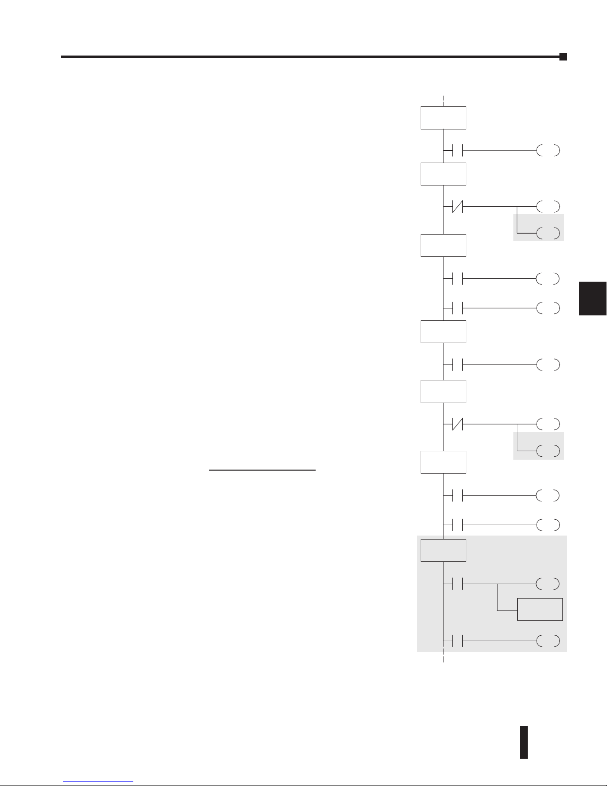
DL06 Micro PLC User Manual, 3rd Edition, Rev. D
7-13
Chapter 7: RLL
PLUS
Stage Programming
1
2
3
4
5
6
7
8
9
10
11
12
13
14
A
B
C
D
Using a Timer Inside a Stage
The finished modified program is shown to the right. The
shaded areas indicate the program additions.
In the Push-UP stage S1, we add the Set Stage Bit S6
instruction. When contact X0 closes, we transition from
S1 and go to two new active states: S2 and S6. In the PushDOWN state S4, we make the same additions. So, any time
someone presses the door control pushbutton, the light turns
on.
Most new stage programmers would be concerned about
where to place the Light Stage in the ladder, and how to
number it. The good news is that it doesn’t matter!
• Just choose an unused Stage number, and use it for the new stage
and as the reference from other stages.
• Placement in the program is not critical, so we place it at the end.
You might think that each stage has to be directly under the
stage that transitions to it. While it is good practice, it is not
required (that’s good, because our two locations for the Set S6
instruction make that impossible). Stage numbers and how
they are used determines the transition paths.
In stage S6, we turn on the safety light by energizing Y3.
Special relay contact SP1 is always on. Timer T0 times at
0.1 second per count. To achieve 3 minutes time period, we
calculate:
The timer has power flow whenever stage S6 is active. The
corresponding timer bit T0 is set when the timer expires. So
three minutes later, T0=1 and the instruction Reset S6 causes
the stage to be inactive.
While Stage S6 is active and the light is on, stage transitions
in the primary path continue normally and independently of
Stage 6. That is, the door can go up, down, or whatever, but
the light will be on for precisely 3 minutes.
1
2
3
4
5
6
7
8
9
10
11
12
13
14
a
B
C
D
S1
X0
JMP
ISG
S0
S2
JMP
SG
S1
OUT
Y1
DOWN State
SP1
S3
X1
JMP
SG
S2
SG
S3
X0
S4
JMP
X0
Push–UP State
RAISE State
UP State
S5
JMP
SG
S4
X0
Push–DOWN State
OUT
Y2
SP1
S0
X2
JMP
SG
S5
LOWER State
OUT
Y3
SP1
S6
T0
RST
SG
S6
LIGHT State
TMR
K1800
T0
S6
SET
S6
SET
K = 3 min. x 60 sec/min
0.1 sec/count
K = 1800 counts
Page 64
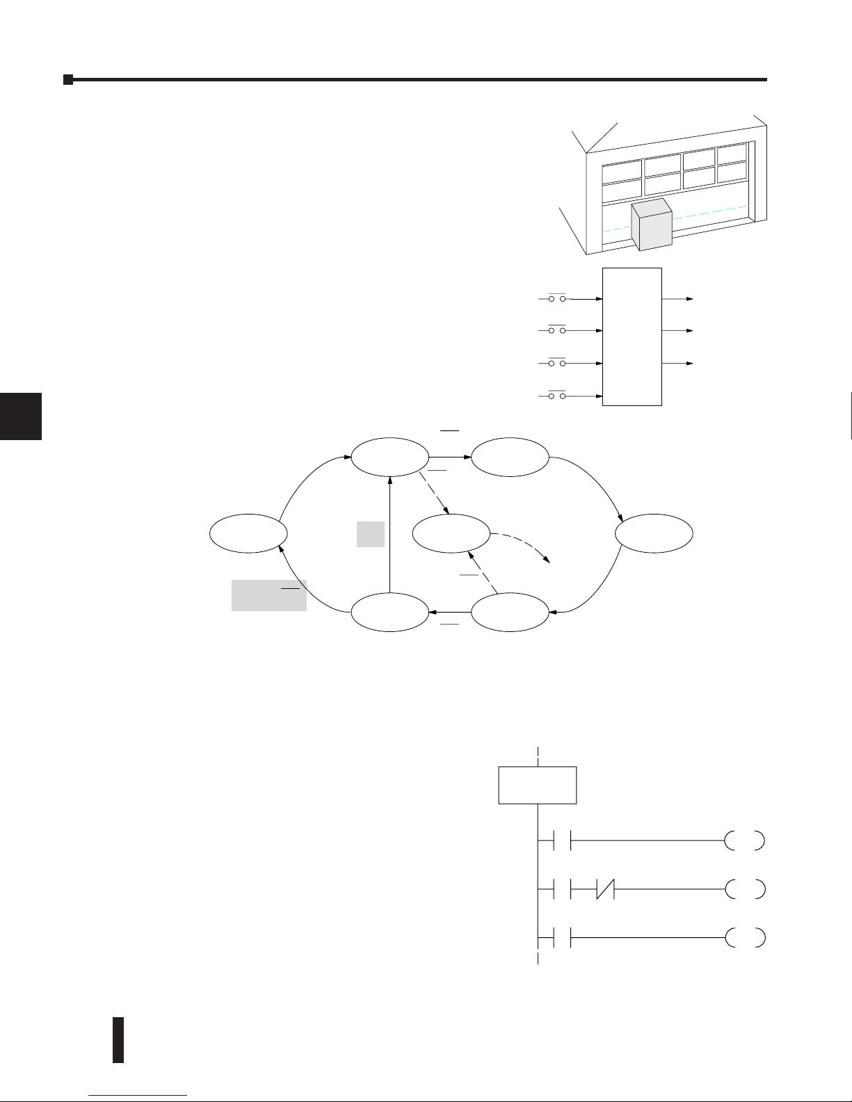
DL06 Micro PLC User Manual, 3rd Edition, Rev. D
7-14
Chapter 7: RLL
PLUS
Stage Programming
1
2
3
4
5
6
7
8
9
10
11
12
13
14
A
B
C
D
Add Emergency Stop Feature
Some garage door openers today will detect an object under
the door. This halts further lowering of the door. Usually
implemented with a photocell (electric-eye), a door in the
process of being lowered will halt and begin raising. We will
define our safety feature to work in this way, adding the input
from the photocell to the block diagram as shown to the
right. X3 will be on if an object is in the path of the door.
Exclusive Transitions
It is theoretically possible that the down limit (X2) and the obstruction input (X3) could
energize at the same moment. In that case, we would jump to the Push-UP and DOWN
states simultaneously, which does not make sense.
Instead, we give priority to the obstruction by
changing the transition condition to the DOWN
state to [X2 AND NOT X3]. This ensures the
obstruction event has the priority. The modifications
we must make to the LOWER Stage (S5) logic
are shown to the right. The first rung remains
unchanged. The second and third rungs implement
the transitions we need. Note the opposite relay
contact usage for X3, which ensures the stage will
execute only one of the JMP instructions.
1
2
3
4
5
6
7
8
9
10
11
12
13
14
a
B
C
D
Ladder
Program
Inputs Outputs
Toggle
X0 Y1
Raise
Y2
Lower
Up limit
X1
Down limit
X2 Y3
Light
Obstruction
X3
X0
Push–UP
UP
Push–DOWN
DOWN
X0
LOWER
RAISE
X0
X1
X0
X2
LIGHT
X0
X0
T0
X3
X3
OUT
Y2
SP1
S0
X2
JMP
SG
S5
LOWER State
X3
S2
X3
JMP
to Push-UP
to DOWN
Next, we make a simple addition to the state transition
diagram, shown in shaded areas in the figure below.
Note the new transition path at the top of the LOWER
state. If we are lowering the door and detect an
obstruction (X3), we then jump to the Push-UP State.
We do this instead of jumping directly to the RAISE
state, to give the Lower output Y2 one scan to turn off,
before the Raise output Y1 energizes.
Page 65
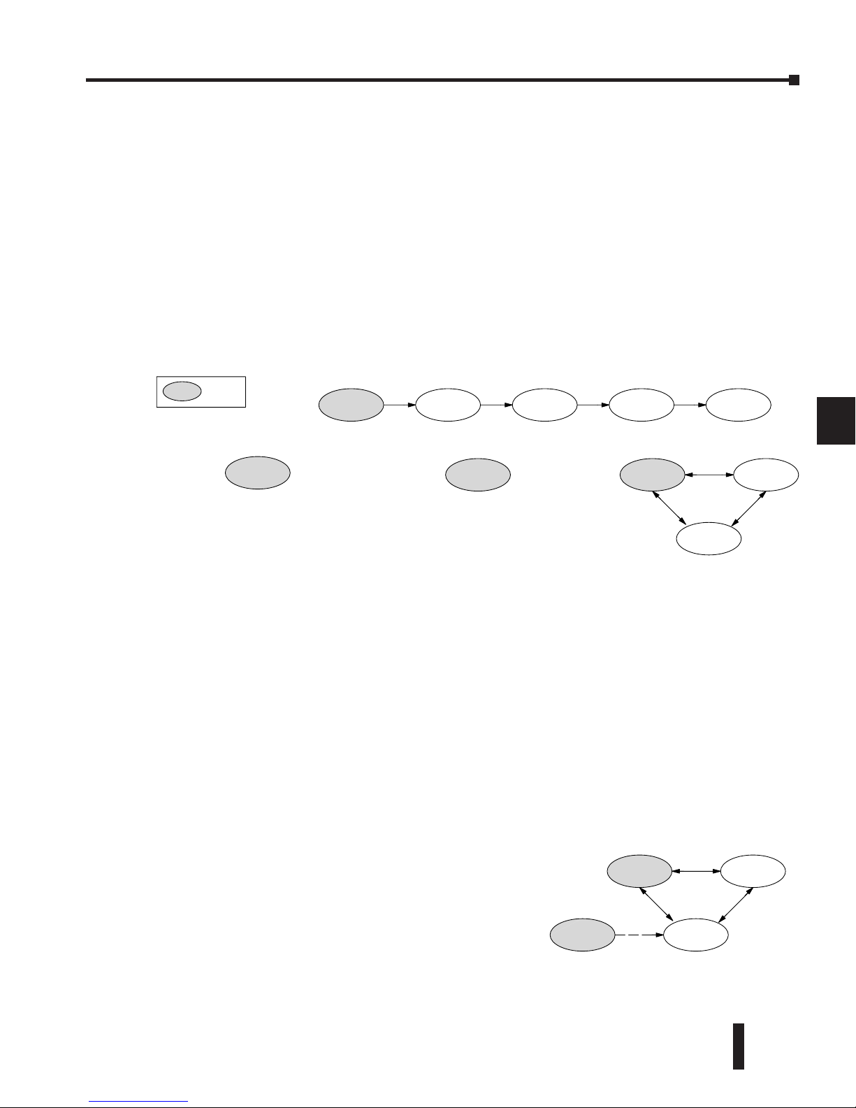
DL06 Micro PLC User Manual, 3rd Edition, Rev. D
7-15
Chapter 7: RLL
PLUS
Stage Programming
1
2
3
4
5
6
7
8
9
10
11
12
13
14
A
B
C
D
Stage Program Design Considerations
Stage Program Organization
The examples so far in this chapter used one self-contained state diagram to represent the
main process. However, we can have multiple processes implemented in stages, all in the
same ladder program. New stage programmers sometimes try to turn a stage on and off each
scan, based on the false assumption that only one stage can be on at a time. For ladder rungs
that you want to execute each scan, just put them in a stage that is always on.
The following figure shows a typical application. During operation, the primary
manufacturing activity Main Process, Powerup Initialization, E-Stop and Alarm Monitoring,
and Operator Interface are all running. At powerup, three initial stages shown begin
operation.
In a typical application, the separate stage sequences above operate as follows:
• Powerup Initi alization – This stage contains ladder rung tasks done just once at powerup. Its last
rung resets the stage, so this stage is only active for one scan (or only as many scans
that are required).
• Main Process –This stage sequence controls the heart of the process or machine. One pass through
the sequence represents one part cycle of the machine, or one batch in the process.
• E-Stop and Al arm Monitoring –This stage is always active because it is watching for errors that
could indicate an alarm condition or require an emergency stop. It is common for
this stage to reset stages in the main process or elsewhere, in order to initialize them
after an error condition.
• Operator Inter face –This is another task that must always be active and ready to respond to an
operator. It allows an operator interface to change modes, etc., independently of the
current main process step.
Although we have separate processes, there can be
coordination among them. For example, in an error
condition, the Status Stage may want to automatically
switch the operator interface to the status mode to show
error information as shown to the right. The monitor
stage could set the stage bit for Status and Reset the
stages Control and Recipe.
1
2
3
4
5
6
7
8
9
10
11
12
13
14
a
B
C
D
Agitate
Monitor
Idle
Fill Rinse Spin
E-Stop and Alarm Monitoring
Main Process
Operator Interface
Control
Recipe
Status
XXX
= ISG
Powerup
Powerup Initialization
Monitor
E-Stop and
Alarm Monitoring
Operator Interface
Control
Recipe
Status
Page 66
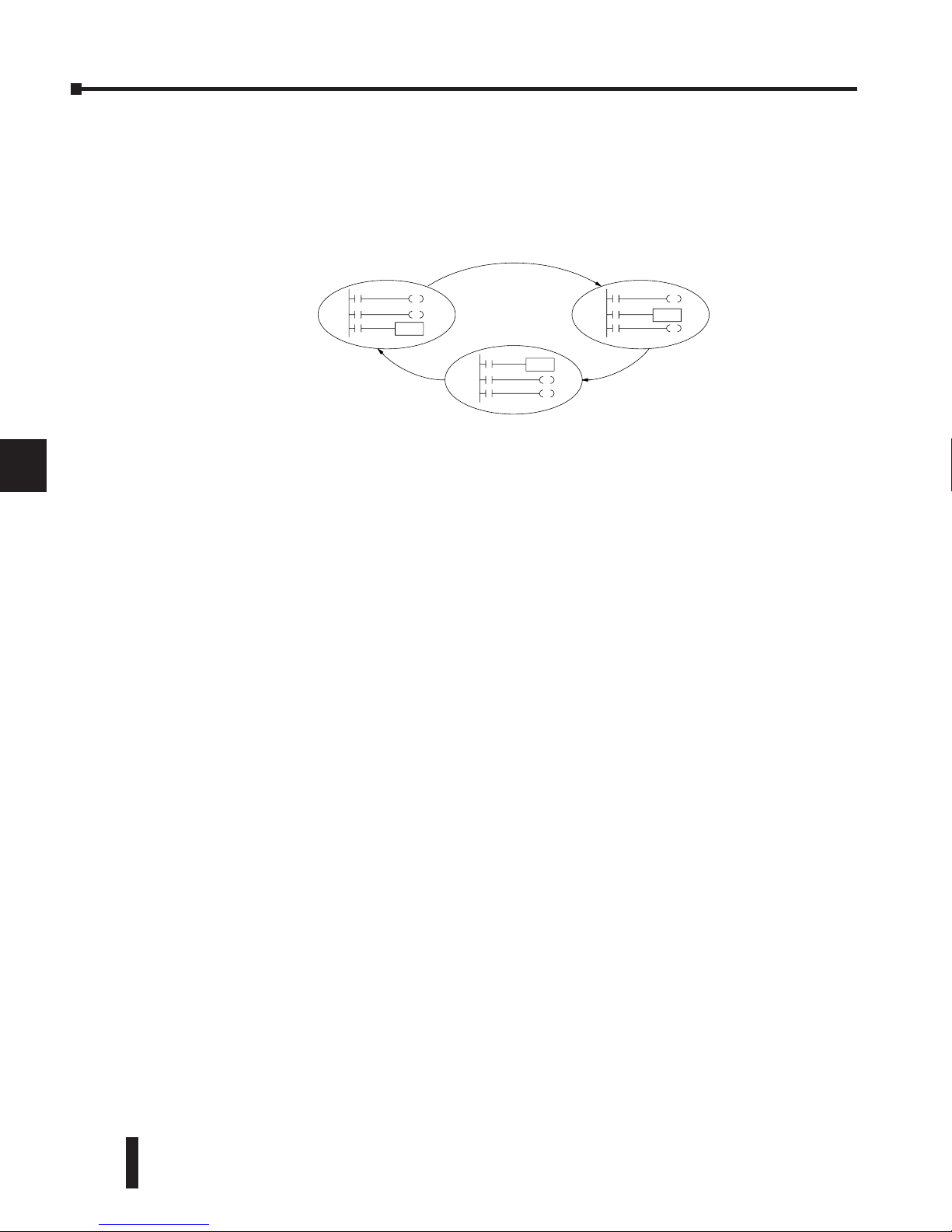
DL06 Micro PLC User Manual, 3rd Edition, Rev. D
7-16
Chapter 7: RLL
PLUS
Stage Programming
1
2
3
4
5
6
7
8
9
10
11
12
13
14
A
B
C
D
How Instructions Work Inside Stages
We can think of states or stages as simply dividing up our ladder program as depicted
in the figure below. Each stage contains only the ladder rungs which are needed for the
corresponding state of the process. The logic for transitioning out of a stage is contained
within that stage. It’s easy to choose which ladder rungs are active at powerup by using an
initial stage type (ISG).
Most all instructions work just like they do in standard RLL. You can think of a stage just
like a miniature RLL program which is either active or inactive.
Output Coils – As expected, output coils in active stages will turn on or off outputs
according to power flow into the coil. However, note the following:
• Outputs work as usual, provided each output reference, such as “Y3”, is used in only one stage.
• An output can be referenced from more than one stage, as long as only one of the stages is active at
a time.
• If an output coil is controlled by more than one stage simultaneously, the active stage nearest the
bottom of the program determines the final output status during each scan. Therefore, use the
OROUT instruction instead when you want multiple stages to have a logical OR control of an
output.
One-Shot or PD coils – Use care if you must use a Positive Differential coil in a stage.
Remember that the input to the coil must make a 0–1 transition. If the coil is already
energized on the first scan when the stage becomes active, the PD coil will not work. This is
because the 0–1 transition did not occur.
PD coil alternative: If there is a task which you want to do only once (on 1 scan), it can be
placed in a stage which transitions to the next stage on the same scan.
Counter – In using a counter inside a stage, the stage must be active for one scan before the
input to the counter makes a 0–1 transition. Otherwise, there is no real transition and the
counter will not count.
The ordinary Counter instruction does have a restriction inside stages: it may not be reset
from other stages using the RST instruction for the counter bit. However, the special Stage
counter provides a solution (see next paragraph).
Stage Counter – The Stage Counter has the benefit that its count may be globally reset from
other stages by using the RST instruction. It has a count input, but no reset input. This is the
only difference from a standard counter.
Drum – Realize that the drum sequencer is its own process, and is a different programming
method than stage programming. If you need to use a drum with stages, be sure to place the
drum instruction in an ISG stage that is always active.
1
2
3
4
5
6
7
8
9
10
11
12
13
14
a
B
C
D
Stage 0 Stage 1
Stage 2
Page 67
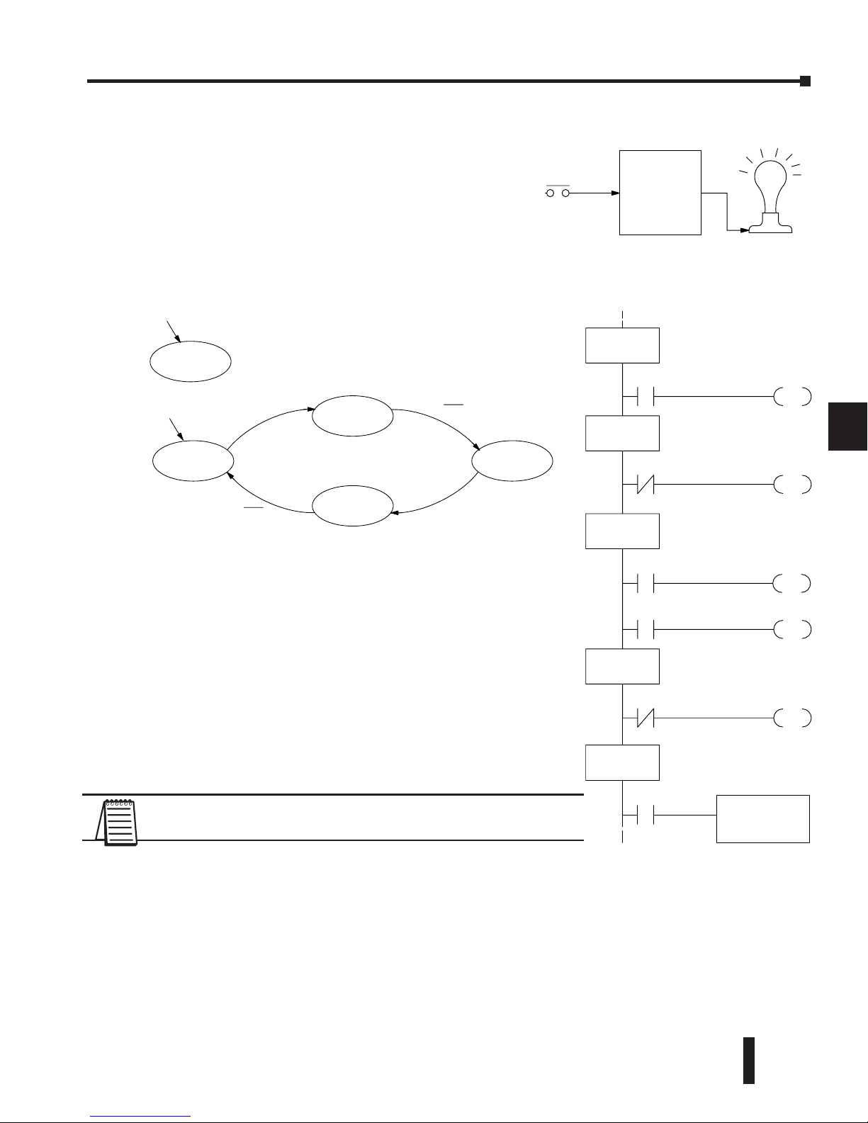
DL06 Micro PLC User Manual, 3rd Edition, Rev. D
7-17
Chapter 7: RLL
PLUS
Stage Programming
1
2
3
4
5
6
7
8
9
10
11
12
13
14
A
B
C
D
Using a Stage as a Supervisory Process
You may recall the light bulb on-off controller
example from earlier in this chapter. For the purpose
of illustration, suppose we want to monitor the
productivity of the lamp process, by counting the
number of on-off cycles which occurs. This application
will require the addition of a simple counter, but the
key decision is in where to put the counter.
New stage programming students will typically try to place
the counter inside one of the stages of the process they are
trying to monitor. The problem with this approach is that
the stage is active only part of the time. In order for the
counter to count, the count input must transition from off
to on at least one scan after its stage activates. Ensuring this
requires extra logic that can be tricky.
In this case, we only need to add another supervisory stage as
shown above, to watch the main process. The counter inside
the supervisor stage uses the stage bit S1 of the main process
as its count input. Stage bits used as a contact let us monitor a
process!
NOTE: Both the Supervisor stage and the OFF stage are initial
stages. The supervisor stage remains active indefinitely.
Stage Counter
The counter in the above example is a special Stage Counter. Note that it does not have a
reset input. The count is reset by executing a Reset instruction, naming the counter bit (CT0
in this case). The Stage Counter has the benefit that its count may be globally reset from
other stages. The standard Counter instruction does not have this global reset capability. You
may still use a regular Counter instruction inside a stage... however, the reset input to the
counter is the only way to reset it.
1
2
3
4
5
6
7
8
9
10
11
12
13
14
a
B
C
D
Ladder
Program
ggle
X0 Y0
S1
X0
JMP
ISG
S0
S2
JMP
SG
S1
OUT
Y0
OFF State
SP1
S3
X0
JMP
SG
S2
SG
S3
X0
S0
JMP
X0
Push–On State
ON State
Push–Off State
SGCNT
K5000
CT0
ISG
S4
S1
Supervisor State
X0
Push–ON
ON
Push–OFF
OFF
X0
X0
X0
Supervisor
Main Process
Supervisor Process
Powerup
Powerup
Page 68
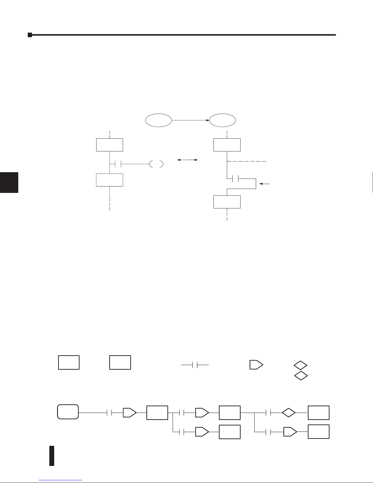
DL06 Micro PLC User Manual, 3rd Edition, Rev. D
7-18
Chapter 7: RLL
PLUS
Stage Programming
1
2
3
4
5
6
7
8
9
10
11
12
13
14
A
B
C
D
Power Flow Transition Technique
Our discussion of state transitions has shown how the Stage JMP instruction makes the
current stage inactive and the next stage (named in the JMP) active. As an alternative way to
enter this in DirectSOFT, you may use the power flow method for stage transitions.
The main requirement is that the current stage be located directly above the next (jump-to)
stage in the ladder program. This arrangement is shown in the diagram below, by stages S0
and S1, respectively.
Remember that the Stage JMP instruction may occur anywhere in the current stage, and the
result is the same. However, power flow transitions, as shown above, must occur as the last
rung in a stage. All other rungs in the stage will precede it. The power flow transition method
is also achievable on the handheld programmer, by simply following the transition condition
with the Stage instruction for the next stage.
The power flow transition method does eliminate one Stage JMP instruction, its only
advantage. However, it is not as easy to make program changes as using the Stage JMP.
Therefore, we advise using Stage JMP transitions for most programmers.
Stage View in DirectSOFT
The Stage View option in DirectSOFT will let you view the ladder program as a flow chart.
The figure below shows the symbol convention used in the diagrams. You may find the stage
view useful as a tool to verify that your stage program has faithfully reproduced the logic of
the state transition diagram you intend to realize.
The following diagram is a typical stage view of a ladder program containing stages. Note the
left-to-right direction of the flow chart.
1
2
3
4
5
6
7
8
9
10
11
12
13
14
a
B
C
D
S1
X0
JMP
SG
S0
Equivalent
X0
SG
S0
S0 S1
X0
SG
S1
SG
S1
All other rungs in stage...
Power flow
transition
Stage Reference to
a Stage
J
Jump
S
Set Stage
R
Reset Stage
Transition
Logic
SG
ISG
SO
SG
S1
SG
S2
SG
S3
SG
S4
SG
S5
JJ
J
S
J
Page 69
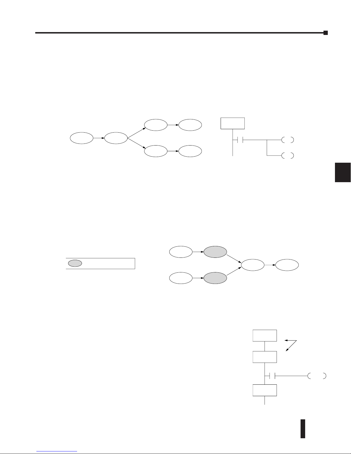
DL06 Micro PLC User Manual, 3rd Edition, Rev. D
7-19
Chapter 7: RLL
PLUS
Stage Programming
1
2
3
4
5
6
7
8
9
10
11
12
13
14
A
B
C
D
Parallel Processing Concepts
Parallel Processes
Previously in this chapter we discussed how a state may transition to either one state or
another, called an exclusive transition. In other cases, we may need to branch simultaneously
to two or more parallel processes, as shown below. It is acceptable to use all JMP instructions
as shown, or we could use one JMP and a Set Stage bit instruction(s) (at least one must be a
JMP, in order to leave S1). Remember that all instructions in a stage execute, even when it
transitions (the JMP is not a GOTO).
Note that if we want Stages S2 and S4 to energize exactly on the same scan, both stages must
be located below or above Stage S1 in the ladder program (see the explanation at the bottom
of page 7–7). Overall, parallel branching is easy!
Converging Processes
Now, we consider the opposite case of parallel branching, which is converging processes. This
simply means we stop doing multiple things and continue doing one thing at a time. In the
figure below, processes A and B converge when stages S2 and S4 transition to S5 at some
point in time. So, S2 and S4 are Convergence Stages.
Convergence Stages (CV)
While the converging principle is simple enough, it brings a new complication. As parallel
processing completes, the multiple processes almost never finish at the same time. In other
words, how can we know whether Stage S2 or S4 will finish last? This is an important point,
because we have to decide how to transition to Stage S5.
The solution is to coordinate the transition condition out of
convergence stages. We accomplish this with a stage type designed
for this purpose: the Convergence Stage (type CV). In the example
to the right, convergence stages S2 and S4 are required to be
grouped together as shown. No logic is permitted between CV
stages! The transition condition (X3 in this case) must be located
in the last convergence stage. The transition condition only has
power flow when all convergence stages in the group are active.
1
2
3
4
5
6
7
8
9
10
11
12
13
14
a
B
C
D
S1S0
S2
S4
S3
S5
S2
JMP
SG
S1
X0
Push–On State
S4
JMP
X0
Process A
Process B
S5
S1
S3
S2
S4
S6
= Convergence Stage
Process A
Process B
CVJMP
S5
X3
CV
S2
CV
S4
Convergence
Stages
SG
S5
Page 70
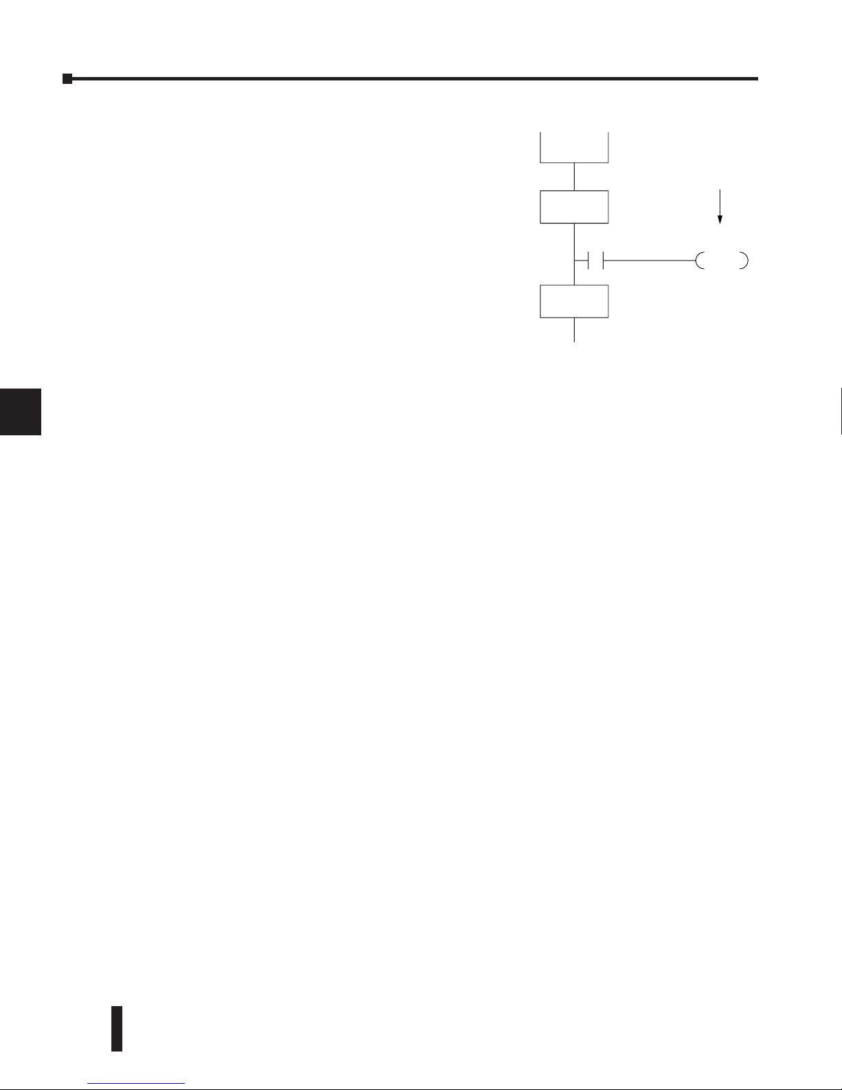
DL06 Micro PLC User Manual, 3rd Edition, Rev. D
7-20
Chapter 7: RLL
PLUS
Stage Programming
1
2
3
4
5
6
7
8
9
10
11
12
13
14
A
B
C
D
Convergence Jump (CVJMP)
Remember, the last convergence stage only has power flow
when all CV stages in the group are active. To complement
the convergence stage, we need a new jump instruction.
The Convergence Jump (CVJMP) shown to the right will
transition to Stage S5 when X3 is active (as one might
expect), but it also automatically resets all convergence stages
in the group. This makes the CVJMP jump a very powerful
instruction. Note that this instruction may only be used
with convergence stages.
Convergence Stage Guidelines
The following summarizes the requirements in the use of
convergence stages, including some tips for their effective application:
• A convergence stage is to be used as the last stage of a process which is running in parallel to another
process or processes. A transition to the convergence stage means that a particular process is finished
and represents a waiting point until all other parallel processes also finish.
• The maximum number of convergence stages which make up one group is 16. In other words, a
maximum of 16 stages can converge into one stage.
• Convergence stages of the same group must be placed together in the program, connected on the
power rail without any other logic in between.
• Within a convergence group, the stages may occur in any order, top to bottom. It does not matter
which stage is last in the group, because all convergence stages have to be active before the last stage
has power flow.
• The last convergence stage of a group may have ladder logic within the stage. However, this logic
will not execute until all convergence stages of the group are active.
• The convergence jump (CVJMP) is the intended method to be used to transition from the
convergence group of stages to the next stage. The CVJMP resets all convergence stages of the
group, and energizes the stage named in the jump.
• The CVJMP instruction must only be used in a convergence stage, as it is invalid in regular or
initial stages.
• Convergence Stages or CVJMP instructions may not be used in subroutines or interrupt routines.
1
2
3
4
5
6
7
8
9
10
11
12
13
14
a
B
C
D
CVJMP
S5
X3
CV
S2
CV
S4
Convergence
Jump
SG
S5
Page 71
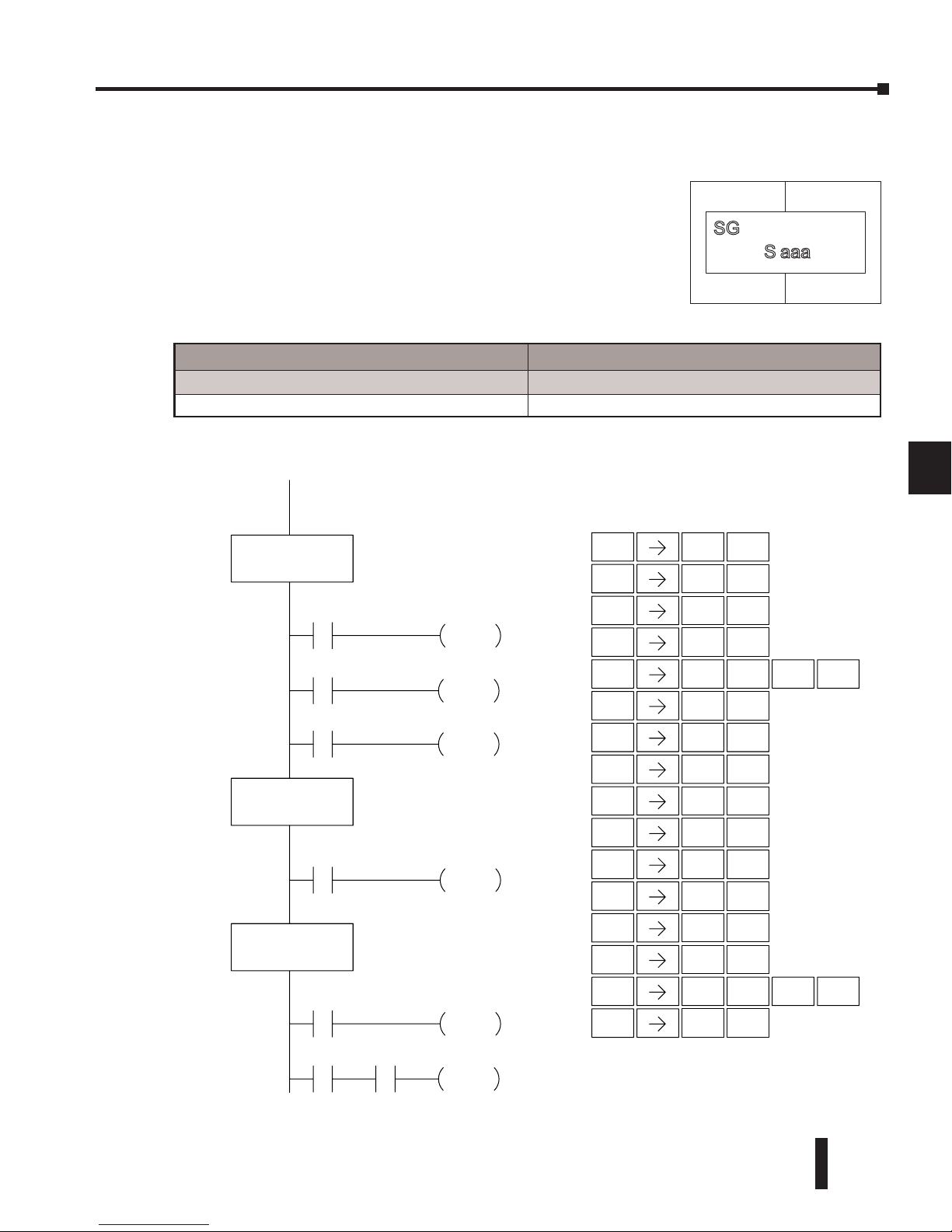
DL06 Micro PLC User Manual, 3rd Edition, Rev. D
7-21
Chapter 7: RLL
PLUS
Stage Programming
1
2
3
4
5
6
7
8
9
10
11
12
13
14
A
B
C
D
RLL
PLUS
(Stage) Instructions
Stage (SG)
The following example is a simple RLL
PLUS
program. This program utilizes an initial stage,
stage, and jump instructions to create a structured program.
1
2
3
4
5
6
7
8
9
10
11
12
13
14
a
B
C
D
aaaS
SG
Operand Data Type DL06 Range
aaa
Stage S 0–1777
X0
ISG S0
Y0
OUT
X1
S2
SET
SG S1
X5
X2
Y1
OUT
SG S2
X6
Y2
OUT
X7
S0
JMP
S1
JMP
S1
Direct SOFT
Handheld Programmer Keystrokes
ISG
U
0
A
ENT
STR
$
OUT
GX
STR
$
SET
X
SHFT
RST
S
2
C
ENT
STR
$
JMP
K
1
B
ENT
SG
2
1
B
ENT
STR
$
OUT
GX
SG
2
ENT
STR
$
OUT
GX
2
C
STR
$
AND
V
SHFT
RST
S
1
B
ENT
JMP
K
ENT
0
A
ENT
0
A
1
B
ENT
ENT
5
F
ENT
2
C
ENT
1
B
ENT
ENT
6
G
2
C
ENT
7
H
0
A
ENT
The Stage instructions are used to create structured RLL
PLUS
programs. Stages are program segments which can be
activated by transitional logic, a jump or a set stage that is
executed from an active stage. Stages are deactivated one scan
after transitional logic, a jump, or a reset stage instruction is
executed.
Page 72
DL06 Micro PLC User Manual, 3rd Edition, Rev. D
7-22
Chapter 7: RLL
PLUS
Stage Programming
1
2
3
4
5
6
7
8
9
10
11
12
13
14
A
B
C
D
Initial Stage (ISG)
The Initial Stage instruction is normally used as the first
segment of an RLL
PLUS
program. Multiple Initial Stages are
allowed in a program. They will be active when the CPU
enters the Run mode allowing for a starting point in the
program. Initial Stages are also activated by transitional logic, a
jump or a set stage executed from an active stage.
NOTE: If the ISG is within the retentive range for stages, the ISG will remain in the state it was in
before power down and will NOT turn itself on during the first scan.
Jump (JMP)
In the following example, only stage ISG0 will be active when program execution begins.
When X1 is on, program execution will jump from Initial Stage 0 to Stage 1.
1
2
3
4
5
6
7
8
9
10
11
12
13
14
a
B
C
D
aaaS
ISG
Operand Data Type DL06 Range
aaa
Stage S 0–1777
Operand Data Type DL06 Range
aaa
Stage S 0–1777
Operand Data Type DL06 Range
aaa
Stage S 0–1777
aaa
S
JMP
aaa
S
NJMP
The Jump instruction allows the program to transition
from an active stage containing the jump instruction to
another stage (specified in the instruction). The jump
occurs when the input logic is true. The active stage
containing the Jump will deactivate 1 scan later.
Not Jump (NJMP)
The Not Jump instruction allows the program to
transition from an active stage which contains the jump
instruction to another which is specified in the instruction.
The jump will occur when the input logic is off. The active
stage that contains the Not Jump will be deactivated 1 scan
after the Not Jump instruction is executed.
Page 73
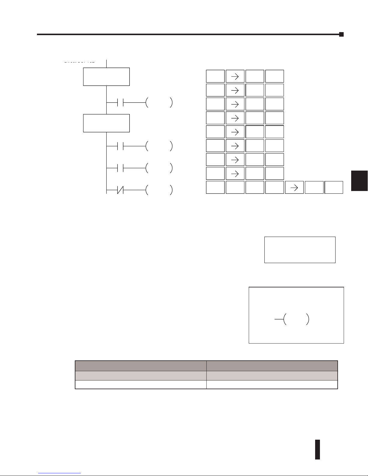
DL06 Micro PLC User Manual, 3rd Edition, Rev. D
7-23
Chapter 7: RLL
PLUS
Stage Programming
1
2
3
4
5
6
7
8
9
10
11
12
13
14
A
B
C
D
Converge Stage (CV) and Converge Jump (CVJMP)
The Converge Stage instruction is used to group certain stages together by defining them as
Converge Stages.
1
2
3
4
5
6
7
8
9
10
11
12
13
14
a
B
C
D
Operand Data Type DL06 Range
aaa
Stage S 0–1777
Direct
SOFT32
Handheld Programmer Keystrokes
ISG S0
X1
S1
JMP
SG S1
X2
Y5
OUT
X7
S2
JMP
S3
NJMP
ISG
U
0
A
ENT
STR
$
JMP
K
1
B
ENT
SG
2
1
B
ENT
STR
$
OUT
GX
STR
$
JMP
K
ENT
2
C
SHFT
TMR
N
SHFT
JMP
K
ENT
3
D
ENT
1
B
ENT
2
C
5
F
ENT
ENT
7
H
X7
S aaa
CV
S aaa
CVJMP
DirectSOFT
When all of the Converge Stages within a group become
active, the CVJMP instruction (and any additional logic
in the final CV stage) will be executed. All preceding CV
stages must be active before the final CV stage logic can be
executed. All Converge Stages are deactivated one scan after
the CVJMP instruction is executed.
Additional logic instructions are only allowed following
the last Converge Stage instruction and before the CVJMP
instruction. Multiple CVJMP instructions are allowed.
Converge Stages must be programmed in the main body
of the application program. This means they cannot be
programmed in Subroutines or Interrupt Routines.
Page 74
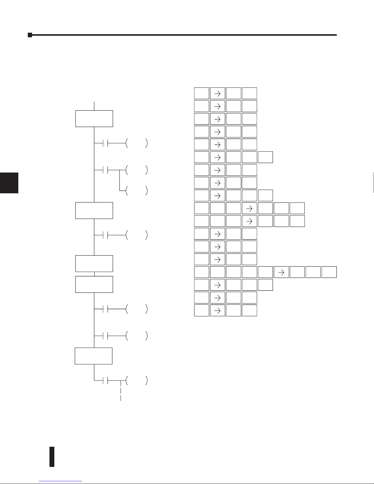
DL06 Micro PLC User Manual, 3rd Edition, Rev. D
7-24
Chapter 7: RLL
PLUS
Stage Programming
1
2
3
4
5
6
7
8
9
10
11
12
13
14
A
B
C
D
In the following example, when Converge Stages S10 and S11 are both active the CVJMP
instruction will be executed when X4 is on. The CVJMP will deactivate S10 and S11, and
activate S20. Then, if X5 is on, the program execution will jump back to the initial stage, S0.
1
2
3
4
5
6
7
8
9
10
11
12
13
14
a
B
C
D
Direct SOFT32
ISG S0
CV S11
X3
Y3
OUT
X4
S20
CVJMP
SG S20
X0
Y0
OUT
X1
S1
JMP
S10
JMP
SG S1
X2
S11
JMP
Handheld Programmer Keystrokes
CV S10
X5
S0
JMP
ISG
U
0
A
ENT
STR
$
JMP
K
1
B
ENT
SG
2
1
B
ENT
STR
$
OUT
GX
JMP
K
ENT
SHFT
JMP
K
ENT
3
D
ENT
1
B
ENT
2
C
ENT
ENT
0
A
OUT
GX
ENT
0
A
STR
$
ENT
JMP
K
1
B
ENT
0
A
1
B
1
B
2CAND
V
1
B
0
A
SHFT
ENT
2CAND
V
1
B
1
B
STR
$
ENT
3
D
4
E
STR
$
ENT
SHFT
ENT
2CAND
V
0
A
SHFT
JMP
K
SG
2
ENT
2
C
0
A
2
C
5
F
STR
$
ENT
0
A
DirectSOFT
Page 75
DL06 Micro PLC User Manual, 3rd Edition, Rev. D
7-25
Chapter 7: RLL
PLUS
Stage Programming
1
2
3
4
5
6
7
8
9
10
11
12
13
14
A
B
C
D
Block Call (BCALL)
The stage block instructions are used to activate a block of stages. The Block Call, Block, and
Block End instructions must be used together. The BCALL instruction is used to activate a
stage block. There are several things you need to know about the BCALL instruction.
• Must Remain Active — The BCALL instruction actually controls all the stages between
the BLK and the BEND instructions even after the stages inside the block have started
executing. The BCALL must remain active or all the stages in the block will automatically
be turned off. If either the BCALL instruction, or the stage that contains the BCALL
instruction goes off, then the stages in the defined block will be turned off automatically.
• Activates First Block Stage — When the BCALL is executed it automatically activates the
first stage following the BLK instructions.
Block (BLK)
The Block instruction is a label which marks the beginning of a block
of stages that can be activated as a group. A Stage instruction must
immediately follow the Start Block instruction. Initial Stage instructions
are not allowed in a block. The control relay (Caaa) specified in Block
instruction must not be used as an output any where else in the program.
Block End (BEND)
1
2
3
4
5
6
7
8
9
10
11
12
13
14
a
B
C
D
C aaa
BCALL
C aaa
BLK
BEND
Operand Data Type DL06 Range
aaa
Control Relay S 0–1777
Operand Data Type DL06 Range
aaa
Control Relay S 0–1777
• Uses CR Numbers — The BCALL appears as an output
coil, but does not actually refer to a Stage number as
you might think. Instead, the block is identified with a
Control Relay (Caaa). This control relay cannot be used
as an output anywhere else in the program.
The Block End instruction is a label used with
the Block instruction. It marks the end of a
block of stages. There is no operand with this
instruction. Only one Block End is allowed per
Block Call.
Page 76
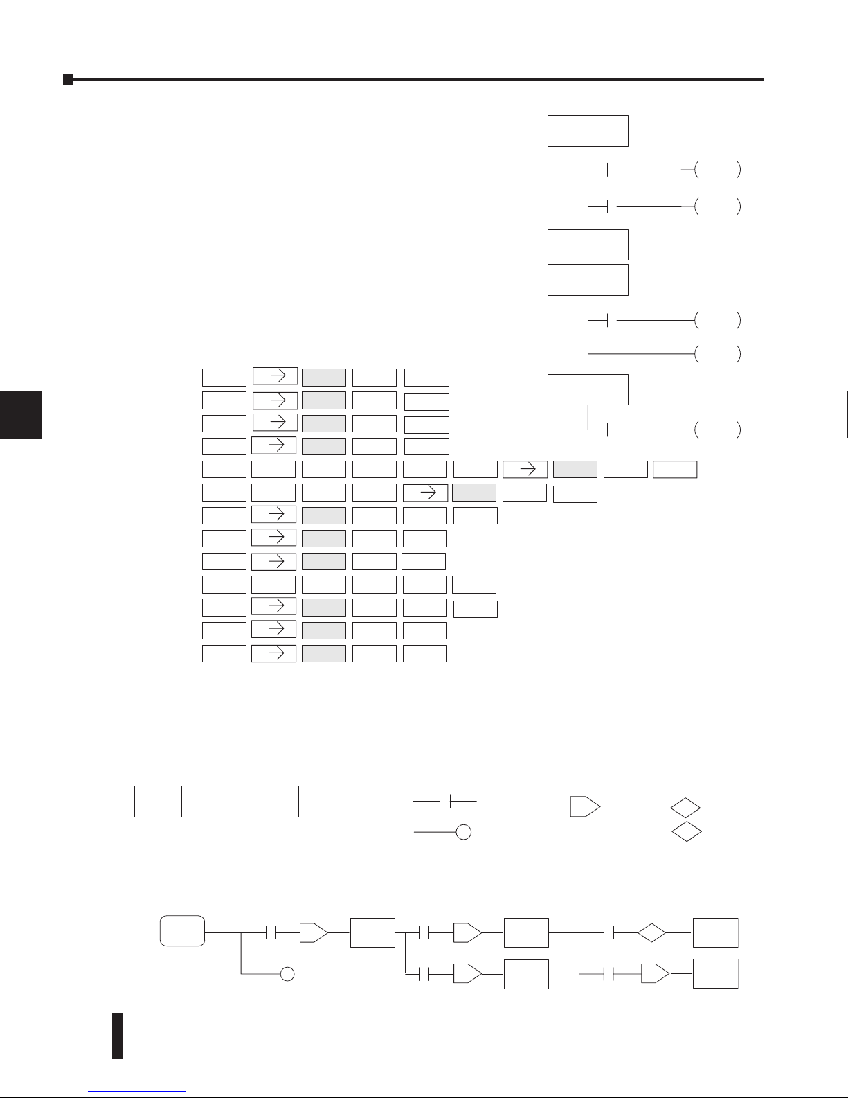
DL06 Micro PLC User Manual, 3rd Edition, Rev. D
7-26
Chapter 7: RLL
PLUS
Stage Programming
1
2
3
4
5
6
7
8
9
10
11
12
13
14
A
B
C
D
In this example, the Block Call is executed when
stage 1 is active and X6 is on. The Block Call then
automatically activates stage S10, which immediately
follows the Block instruction.
This allows the stages between S10 and the Block
End instruction to operate as programmed. If
the BCALL instruction is turned off, or if
the stage containing the BCALL instruction is
turned off, then all stages between the BLK and
BEND instructions are automatically turned off.
If you examine S15, you will notice that X7
could reset Stage S1, which would disable the
BCALL, thus resetting all stages within the block.
Stage View in DirectSOFT
The Stage View option in DirectSOFT will let you view the ladder program as a flow chart.
The figure below shows the symbol convention used in the diagrams. You may find the stage
view useful as a tool to verify that your stage program has faithfully reproduced the logic of
the state transition diagram you intend to realize.
The following diagram is a typical stage view of a ladder program containing stages. Note the
left-to-right direction of the flow chart.
1
2
3
4
5
6
7
8
9
10
11
12
13
14
a
B
C
D
1
Handheld Programmer Keystrokes
SG S(SG)
STR X(IN) 2
OUT Y(OUT) 5
STR X(IN) 6
STR X(IN) 3
SHFT B C A L L C(CR)
SHFT B L K
SG S(SG) 1 0
0
C(CR) 0
OUT Y(OUT) 6
SHFT
RST
STR X(IN) 7
B E N D
S(SG) 1
SG 1S(SG) 5
ENT
ENT
ENT
ENT
ENT
ENT
ENT
ENT
ENT
ENT
ENT
ENT
ENT
SG
Stage
Reference to
a Stage
J
Jump
S
Set Stage
R
Reset
Stage
Transition
Logic
Output
ISG
S0
SG
S1
SG
S2
SG
S3
SG
S4
SG
S5
J J
J
S
J
Direct SOFT32
SG
S1
BLK
C0
X3
Y6
OUT
X7
S1
RST
SG
S15
X2
Y5
OUT
X6
C0
BCALL
SG
S10
BEND
DirectSOFT
Page 77

DL06 Micro PLC User Manual, 3rd Edition, Rev. D
7-27
Chapter 7: RLL
PLUS
Stage Programming
1
2
3
4
5
6
7
8
9
10
11
12
13
14
A
B
C
D
Questions and Answers about Stage Programming
We include the following commonly-asked questions about Stage Programming as an aid to
new students. All question topics are covered in more detail in this chapter.
Q. What does stage programming do that I can’t do with regular RLL programs?
A. Stages allow you to identify all the states of your process before you begin programming.
This approach is more organized, because you divide up a ladder program into sections. As
stages, these program sections are active only when they are actually needed by the process.
Most processes can be organized into a sequence of stages, connected by event-based
transitions.
Q. What are Stage Bits?
A. A stage bit is just a single bit in the CPU’s image register, representing the active/inactive
status of the stage in real time. For example, the bit for Stage 0 is referenced as “S0”. If S0
= 0, then the ladder rungs in Stage 0 are bypassed (not executed) on each CPU scan. If
S0 = 1, then the ladder rungs in Stage 0 are executed on each CPU scan. Stage bits, when
used as contacts, allow one part of your program to monitor another part by detecting
stage active/inactive status.
Q. How does a stage become active?
A. There are three ways:
• If the Stage is an initial stage (ISG), it is automatically active at powerup.
• Another stage can execute a Stage JMP instruction naming this stage, which makes it active upon its
next occurrence in the program.
• A program rung can execute a Set Stage Bit instruction (such as Set S0).
Q. How does a stage become inactive?
A. There are three ways:
• Standard Stages (SG) are automatically inactive at powerup.
• A stage can execute a Stage JMP instruction, resetting its Stage Bit to 0.
• Any rung in the program can execute a Reset Stage Bit instruction (such as Reset S0).
Q. What about the power flow technique of stage transitions?
A. The power flow method of connecting adjacent stages (directly above or below in the
program) actually is the same as the Stage Jump instruction executed in the stage above,
naming the stage below. Power flow transitions are more difficult to edit in DirectSOFT,
we list them separately from two preceding questions.
Q. Can I have a stage which is active for only one scan?
A. Yes, but this is not the intended use for a stage. Instead, just make a ladder rung active for
1 scan by including a stage Jump instruction at the bottom of the rung. Then the ladder
will execute on the last scan before its stage jumps to a new one.
1
2
3
4
5
6
7
8
9
10
11
12
13
14
a
B
C
D
Page 78

DL06 Micro PLC User Manual, 3rd Edition, Rev. D
7-28
Chapter 7: RLL
PLUS
Stage Programming
1
2
3
4
5
6
7
8
9
10
11
12
13
14
A
B
C
D
Q. Isn’t a Stage JMP just like a regular GOTO instruction used in software?
A. No, it is very different. A GOTO instruction sends the program execution immediately
to the code location named by the GOTO. A Stage JMP simply resets the Stage Bit of the
current stage, while setting the Stage Bit of the stage named in the JMP instruction. Stage
bits are 0 or 1, determining the inactive/active status of the corresponding stages. A stage
JMP has the following results:
• When the JMP is executed, the remainder of the current stage’s rungs are executed, even if they
reside past(under) the JMP instruction. On the following scan, that stage is not executed, because it
is inactive.
• The Stage named in the Stage JMP instruction will be executed upon its next occurrence. If located
past (under) the current stage, it will be executed on the same scan. If located before (above) the
current stage, it will be executed on the following scan.
Q. How can I know when to use stage JMP, versus a Set Stage Bit or Reset Stage
Bit?
A. These instructions are used according to the state diagram topology you have derived:
• Use a Stage JMP instruction for a state transition ... moving from one state to another.
• Use a Set Stage Bit instruction when the current state is spawning a new parallel state or stage
sequence, or when a supervisory state is starting a state sequence under its command.
• Use a Reset Bit instruction when the current state is the last state in a sequence and its task is
complete, or when a supervisory state is ending a state sequence under its command.
Q. What is an initial stage, and when do I use it?
A. An initial stage (ISG) is automatically active at powerup. Afterwards, it works just like any
other stage. You can have multiple initial stages, if required. Use an initial stage for ladder
that must always be active, or as a starting point.
Q. Can I place program ladder rungs outside of the stages, so they are always
on?
A. It is possible, but it’s not good software design practice. Place ladder that must always be
active in an initial stage, and do not reset that stage or use a Stage JMP instruction inside
it. It can start other stage sequences at the proper time by setting the appropriate Stage
Bit(s).
Q. Can I have more than one active stage at a time?
A. Yes, and this is a normal occurrence for many programs. However, it is important to
organize your application into separate processes, each made up of stages. And a good
process design will be mostly sequential, with only one stage on at a time. However, all the
processes in the program may be active simultaneously.
1
2
3
4
5
6
7
8
9
10
11
12
13
14
a
B
C
D
Page 79

PID LooP
oPeratIon
8
8
8
Chapter
Chapter
Chapter
In This Chapter...
DL06 PID Control ................................................................................ 8–2
Introduction to PID Control ................................................................. 8–4
Introducing DL06 PID Control ............................................................. 8–6
PID Loop Operation ............................................................................. 8–9
Ten Steps to Successful Process Control ............................................. 8–16
PID Loop Setup .................................................................................. 8–18
PID Loop Tuning ................................................................................ 8–40
Using the Special PID Features ........................................................... 8–53
Ramp/Soak Generator ........................................................................ 8–58
DirectSOFT Ramp/Soak Example ........................................................ 8–63
Cascade Control ................................................................................ 8–65
Time-Proportioning Control ............................................................... 8–68
Feedforward Control .......................................................................... 8–70
PID Example Program ........................................................................ 8–72
Troubleshooting Tips ......................................................................... 8–75
Glossary of PID Loop Terminology ..................................................... 8–77
Bibliography ..................................................................................... 8–79
Page 80
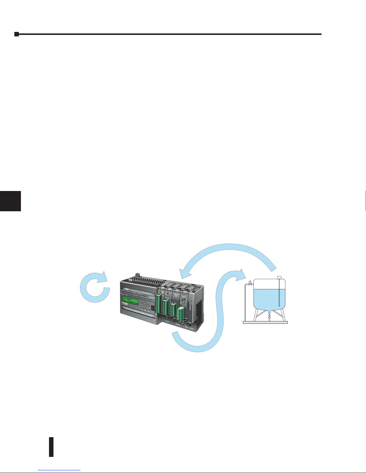
DL06 Micro PLC User Manual, 3rd Edition, Rev. D
8-2
Chapter 8: PID Loop Operation
1
2
3
4
5
6
7
8
9
10
11
12
13
14
A
B
C
D
DL06 PID Control
DL06 PID Control Features
Along with control functions discussed in this manual, the DL06 PLC features PID process
control capability. The DL06 PID process control loops offer the same features offered in
much larger PLCs. The primary features are:
• Up to 8 PID loops, individual programmable sample rates
• Manual, Automatic and Cascade loop operation modes
• Two types of bumpless transfer available
• Full-featured alarms
• Ramp/soak generator with up to 16 segments
• Auto Tuning
The DL06 CPU has process control loop capability in addition to ladder program execution.
You can select and configure up to eight loops. All sensor and actuator wiring connects
directly to DL06 analog modules. All process variables, gain values, alarm levels, etc.,
associated with each loop reside in a Loop Variable Table in the CPU. The DL06 CPU reads
process variable (PV) inputs during each scan. Then, it makes PID loop calculations during a
dedicated time slice on each PLC scan, updating the control output value. The control loops
use a Proportional-Integral-Derivative (PID) algorithm to generate the control output. This
chapter describes how the loops operate, and how to configure and tune the loops.
DirectSOFT programming software, release 5, or later, is used for configuring analog control
loops in the DL06. DirectSOFT uses dialog boxes to help you set up the individual loops.
After completing the setup, you can use DirectSOFT’s PID Trend View to tune each loop.
The configuration and tuning selections you make are stored in the DL06’s V-memory
(RAM). The loop parameters also may be saved to disk for recall later.
1
2
3
4
5
6
7
8
9
10
11
12
13
14
A
B
C
D
Manufacturing Process
DL06
PID Loop Calculations
Analog Output
Analog Input
Page 81

DL06 Micro PLC User Manual, 3rd Edition, Rev. D
8-3
Chapter 8: PID Loop Operation
1
2
3
4
5
6
7
8
9
10
11
12
13
14
A
B
C
D
1
2
3
4
5
6
7
8
9
10
11
12
13
14
A
B
C
D
PID Loop Feature Specifications
Number of loops Selectable, 8 maximum
CPU V-memory needed 32 words (V locations) per loop selected, 64 words if using ramp/soak
PID algorithm Position or Velocity form of the PID equation
Control Output polarity Selectable direct-acting or reverse-acting
Error term curves Selectable as linear, square root of error, and error squared
Loop update rate (time between
PID calculation)
0.05 to 99.99 seconds, user programmable
Minimum loop update rate
0.05 seconds for 1 to 4 loops
0.1 seconds for 5 to 8 loops
Loop modes Automatic, Manual (operator control), or Cascade control
Ramp/Soak Generator Up to 8 ramp/soak steps (16 segments) per loop with indication of ramp/soak step number
PV curves Select standard linear, or square-root extract (for flow meter input)
Set Point Limits Specify minimum and maximum setpoint values
Process Variable Limits Specify minimum and maximum Process Variable values
Proportional Gain Specify gains of 0.01 to 99.99
Integrator (Reset) Specify reset time of 0.1 to 99.99 in units of seconds or minutes
Derivative (Rate) Specify the derivative time from 0.01 to 99.99 seconds
Rate Limits Specify derivative gain limiting from 1 to 20
Bumpless Transfer I
Automatically sets the bias equal to the control output and the setpoint equal to the process
variable when control switches from manual to automatic.
Bumpless Transfer II
Automatically sets the bias equal to the control output when control switches from manual to
automatic.
Step Bias Provides proportional bias adjustment for large setpoint changes
Anti-windup (Freeze Bias)
For position form of PID, this inhibits integrator action when the control output reaches 0% or
100 % (speeds up loop recovery when output recovers from saturation)
Error Deadband
Specify a tolerance (plus and minus) for the error term (SP–PV), so that no change in control
output value is made
Alarm Feature Specifications
PV Alarm Hysteresis Specify 1 to 200 (word/binary) does not affect all alarms, such as PV Rate-of-Change Alarm
PV Alarm Points Select PV alarm settings for Low–low, Low, High, and High-high conditions
PV Deviation Specify alarms for two ranges of PV deviation from the setpoint value
Rate of Change Detect when PV exceeds a rate of change limit you specify
Page 82
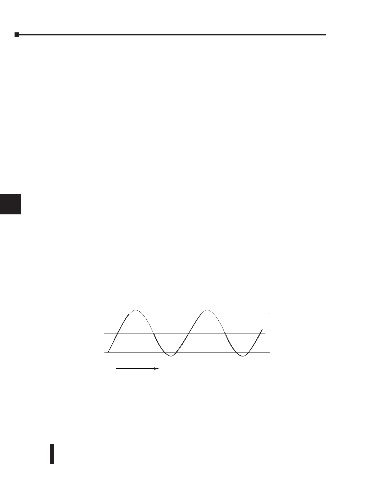
DL06 Micro PLC User Manual, 3rd Edition, Rev. D
8-4
Chapter 8: PID Loop Operation
1
2
3
4
5
6
7
8
9
10
11
12
13
14
A
B
C
D
1
2
3
4
5
6
7
8
9
10
11
12
13
14
A
B
C
D
Introduction to PID Control
What is PID Control?
In this discussion, we will explain why PID control is used in process control instead of trying
to provide control by simply using an analog input and a discrete output.
There are many types of analog controllers available, and the proper selection will depend
upon the particular application. There are two types of analog controllers that are used
throughout industry:
1. The ON-OFF controller, sometimes referred to as an open loop controller.
2. The PID controller, sometimes called a closed loop controller.
Regardless of type, analog controllers require input signals from electronic sensors such as
pressure, differential pressure, level, flow meter or thermocouples. As an example, one of the
most common analog control applications is located in your house for controlling either heat
or air conditioning, the thermostat.
You wish for your house to be at a comfortable temperature so you set a thermostat to a
desired temperature (setpoint). You then select the comfort mode, either heat or A/C. A
temperature sensing device, normally a thermistor, is located within the thermostat. If the
thermostat is set for heat and the setpoint is set for 69!, the furnace will be turned on to
provide heat at, normally, 2! below the setpoint. In this case, it would turn on at 67!. When
the temperature reaches 71!, 2! above setpoint, the furnace will turn off. In the opposite
example, if the thermostat is set for A/C (cooling), the thermostat will turn the A/C unit on/
off opposite the heat setting. For instance, if the thermostat is set to cool at 76!, the A/C unit
will turn on when the sensed temperature reaches 2! above the setpoint or 78!, and turn off
when the temperature reaches 74!. This would be considered to be an ON-OFF controller.
The waveform below shows the action of the heating cycle. Note that there is a slight
overshoot at the turn-off point, also a slight undershoot at the turn-on point.
The ON-OFF controller is used in some industrial control applications, but is not practical
in the majority of industrial control processes.
The most common process controller that is used in industry is the PID controller.
69°
71°
67°
SETPOINT
TIME
OFF
ON
ONON
OFF
Page 83

DL06 Micro PLC User Manual, 3rd Edition, Rev. D
8-5
Chapter 8: PID Loop Operation
1
2
3
4
5
6
7
8
9
10
11
12
13
14
A
B
C
D
The PID controller controls a continuous feedback loop that keeps the process output
(control variable) flowing normally by taking corrective action whenever there is a
deviation from the desired value (setpoint) of the process variable (PV) such as, rate of flow,
temperature, voltage, etc. An error occurs when an operator manually changes the setpoint or
when an event (valve opened, closed, etc.) or a disturbance (cold water, wind, etc.) changes
the load, thus causing a change in the process variable.
The PID controller receives signals from sensors and computes corrective action to the
actuator from a computation based on the error (Proportional), the sum of all previous errors
(Integral) and the rate of change of the error (Derivative).
We can look at the PID controller in more simple terms. Take the cruise control on an
automobile as an example. Let’s say that we are cruising on an interstate highway in a car
equipped with cruise control. The driver decides to engage the cruise control by turning it
ON, then he manually brings the car to the desired cruising speed, say 70 miles per hour.
Once the cruise speed is reached, the SET button is pushed fixing the speed at 70 mph, the
setpoint. Now, the car is cruising at a steady 70 mph until it comes to a hill to go up. As
the car goes up the hill, it tends to slow down. The speed sensor senses this and causes the
throttle to increase the fuel to the engine. The vehicle speeds up to maintain 70 mph without
jerking the car and it reaches the top at the set speed. When the car levels out after reaching
the top of the hill it will speed up. The speed sensor senses this and signals the throttle to
provide less fuel to the engine, thus, the engine slows down allowing the car to maintain the
70 mph speed. How does this application apply to PID control? Lets look at the function of
P, I and D terms:
• Proportional - is commonly referred to as Proportional Gain. The proportional term
is the corrective action which is proportional to the error, that is, the change of the
manipulated variable is equal to the proportional gain multiplied by the error (the
activating signal). In mathematical terms:
Proportional action = proportional gain X error
Error = Setpoint (SP) - Process Variable (PV)
Applying this to the cruise control, the speed was set at 70 mph which is the Setpoint.
The speed sensor senses the actual speed of the car and sends this signal to the cruise
controller as the Process Variable (PV). When the car is on a level highway, the speed is
maintained at 70 mph, thus, no error since the error would be SP - PV = 0. When the
car goes up the hill, the speed sensor detected a slow down of the car, SP-PV = error. The
proportional gain would cause the output of the speed controller to bring the car back to
the setpoint of 70 mph. This would be the Controlled Output.
• Integral - this term is often referred to as Reset action. It provides additional
compensation to the control output, which causes a change in proportion to the value of
the error over a period of time. In other words, the reset term is the integral sum of the
error values over a period of time.
• Derivative - this term is referred to as rate. The Rate action adds compensation to the
control output, which causes a change in proportion to the rate of change of error. Its job
is to anticipate the probable growth of the error and generate a contribution to the output
in advance.
1
2
3
4
5
6
7
8
9
10
11
12
13
14
A
B
C
D
Page 84

DL06 Micro PLC User Manual, 3rd Edition, Rev. D
8-6
Chapter 8: PID Loop Operation
1
2
3
4
5
6
7
8
9
10
11
12
13
14
A
B
C
D
Introducing DL06 PID Control
The DL06 is capable of controlling a process variable such as those already mentioned.
As previously mentioned, the control of a variable, such as temperature, at a given level
(setpoint) as long as there are no disturbances (cold water) in the process.
The DL06 PLC has the ability to directly accept signals from electronic sensors, such as
thermocouples, pressure, VFDs, etc. These signals may be used in mathematically derived
control systems.
In addition, the DL06 has built-in PID control algorithms that can be implemented. The
basic function of PID closed loop process control is to maintain certain process characteristics
at desired setpoints. As a rule, the process deviates from the desired setpoint reference as a
result of load material changes and interaction with other processes. During this control,
the actual condition of the process characteristics (liquid level, temperature, motor control,
etc.) is measured as a process variable (PV) and compared with the target setpoint (SP). When
deviations occur, an error is generated by the difference between the process variable (actual
value) and the setpoint (desired value). Once an error is detected, the function of the control
loop is to modify the control output in order to force the error to zero.
The DL06 PID control provides feedback loops using the PID algorithm. The control output
is computed from the measured process variable as follows:
Let:
Kc = proportional gain
Ti = Reset or integral time
Td = Derivative time or rate
SP = Setpoint
PV(t) = Process Variable at time “t”
e(t) = SP-PV(t) = PV deviation from setpoint at time “t” or PV error.
Then:
M(t) = Control output at time “t”
M(t) = Kc
[ e(t) + 1/T
i
*
0
t
e(x) dx + T
d
d/dt e(t) ] + M
o
The analog input module receives the process variable in analog form along with an
operator entered setpoint; the CPU computes the error. The error is used in the algorithm
computation to provide corrective action at the control output. The function of the control
action is based on an output control, which is proportional to the instantaneous error value.
The integral control action (reset action) provides additional compensation to the control
output, which causes a change in proportion to the value of the change of error over a period
of time. The derivative control action (rate change) adds compensation to the control output,
which causes a change in proportion to the rate of change of error. These three modes are
used to provide the desired control action in Proportional (P), Proportional-Integral (PI), or
Proportional-Integral-Derivative (PID) control fashion.
1
2
3
4
5
6
7
8
9
10
11
12
13
14
A
B
C
D
Page 85
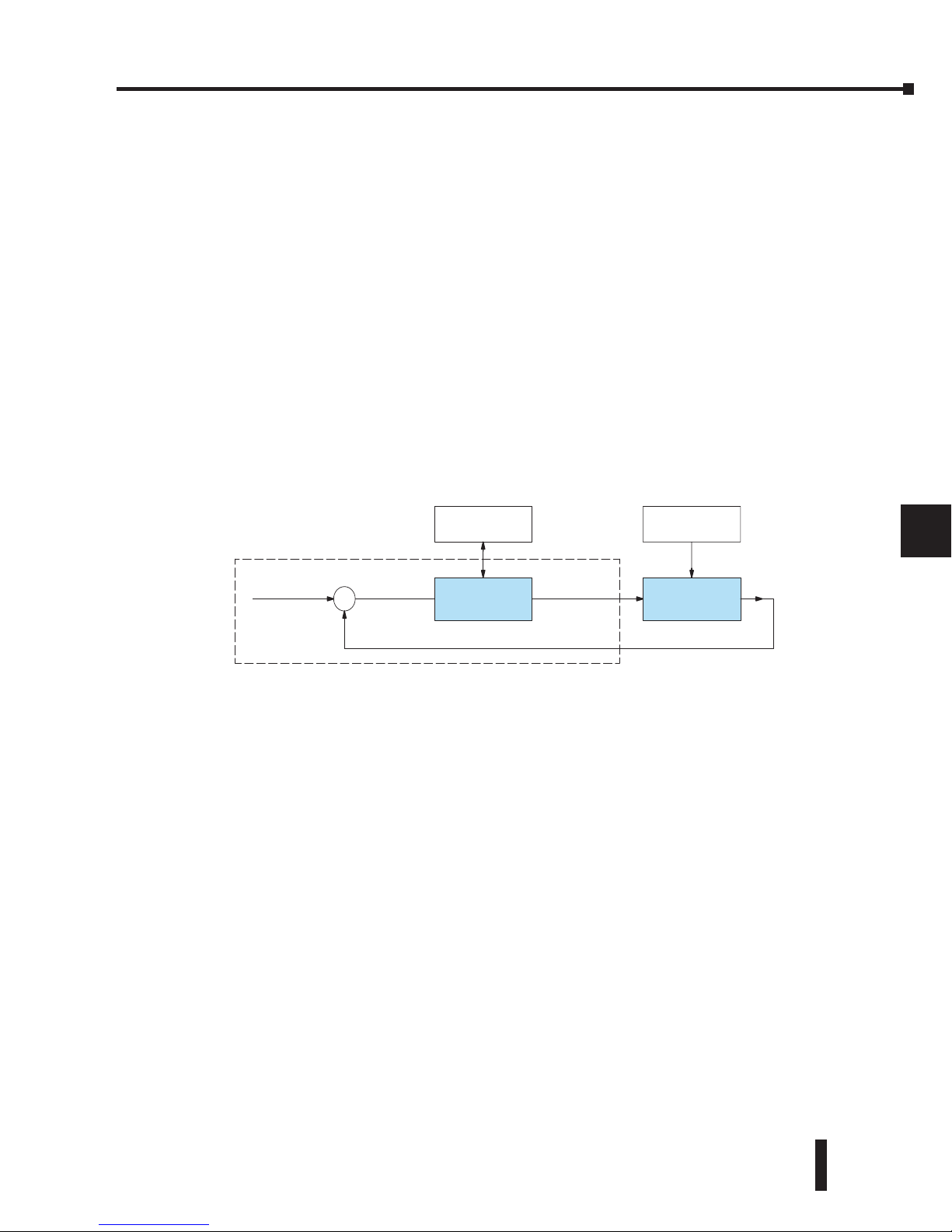
DL06 Micro PLC User Manual, 3rd Edition, Rev. D
8-7
Chapter 8: PID Loop Operation
1
2
3
4
5
6
7
8
9
10
11
12
13
14
A
B
C
D
1
2
3
4
5
6
7
8
9
10
11
12
13
14
A
B
C
D
Standard DL05/06 analog input modules are used to interface to field transmitters to obtain
the PV. These transmitters normally provide a 4-20mA current or an analog voltage of
various ranges for the control loop.
For temperature control, thermocouple or RTD can be connected directly to the appropriate
module. The PID control algorithm, residing in the CPU memory, receives information from
the user program, primarily control parameters and setpoints. Once the CPU makes the PID
calculation, the result may be used to directly control an actuator connected to a 4-20mA
current output module to control a valve.
With DirectSOFT, additional ladder logic programming, both time proportioning (eg.,
heaters for temperature control) and position actuator (eg., reversible motor on a valve) type
of control schemes can be easily implemented. This chapter will explain how to set up the
PID control loop, how to implement the software and how to tune the loop.
The following block diagram shows the key parts of a PID control loop. The path from the
PLC to the manufacturing process and back to the PLC is the closed loop control.
Process Variable
Loop
Calculation
Manufacturing
Process
Setpoint Value
Loop Configuring
and Monitoring
Control Output
External
Disturbances
Error Term
+
–
PLC System
Page 86

DL06 Micro PLC User Manual, 3rd Edition, Rev. D
8-8
Chapter 8: PID Loop Operation
1
2
3
4
5
6
7
8
9
10
11
12
13
14
A
B
C
D
Process Control Definitions
Manufacturing Process – the set of actions that adds value to raw materials. The process can
involve physical changes and/or chemical changes to the material. The changes render the
material more useful for a particular purpose, ultimately used in a final product.
Process Variable – The controlled variable part of the process that you wish to control. It
may be temperature, pressure, level, flow, composition, density, the ratio of two streams, etc.
Also known as the actual value.
Setpoint – This is the target for the process variable. When all conditions of the process are
correct, the process variable will equal the setpoint.
Control Output – The result of the loop calculation, which becomes a command for the
process (such as the heater level in an oven). This is sometimes referred to as control variable.
Error Term – The algebraic difference between the process variable and the setpoint. This is
the control loop error, and is equal to zero when the process variable is equal to the setpoint
(desired) value. A well-behaved control loop is able to maintain a small error term magnitude.
Manipulated Variable – This is what is used to effect the controlled variable. For example,
the fuel used in a furnace might be manipulated in order to control the temperature.
Disturbance – Something in the system that changes such that corrective action is required.
For instance, when controlling a flow and the upstream pressure drops, the control valve must
open wider in order to keep flow constant. The drop in upstream pressure is the disturbance.
Final Control Element – This is the physical device used to control the manipulated variable.
Valves are probably the most widely used final control element.
Lag Time – The time it takes for the process to respond to a change in manipulated variable.
This is also known as the capacitance of the system. When you’re in the shower and you turn
up the hot water a little, the time it takes before the water gets hot is the lag time.
Dead Time – The time it takes for a change in the process to be recognized. Composition
analyzers and quality control are usually sources of significant dead time.
Loop Configuring – Operator-initiated selections which set up and optimize the performance
of a control loop. The loop calculation function uses the configuration parameters in real
time to adjust gains, offsets, etc.
Loop Monitoring – The function which allows an operator to observe the status and
performance of a control loop. This is used in conjunction with the loop configuring to
optimize the performance of a loop (minimize the error term).
1
2
3
4
5
6
7
8
9
10
11
12
13
14
A
B
C
D
Page 87

DL06 Micro PLC User Manual, 3rd Edition, Rev. D
8-9
Chapter 8: PID Loop Operation
1
2
3
4
5
6
7
8
9
10
11
12
13
14
A
B
C
D
1
2
3
4
5
6
7
8
9
10
11
12
13
14
A
B
C
D
PID Loop Operation
The Proportional–Integral–Derivative (PID) algorithm is widely used in process control. The
PID method of control adapts well to electronic solutions, whether implemented in analog
or digital (CPU) components. The DL06 CPU implements the PID equations digitally by
solving the basic equations in software. I/O modules serve only to convert electronic signals
into digital form (or vice versa).
The DL06 uses two types of PID controls: “position” and “velocity”. These terms usually
refer to motion control situations, but here we use them in a different sense:
• PID Position Algorithm – The control output is calculated so it responds to the
displacement (position) of the PV from the SP (error term).
• PID Velocity Algorithm – The control output is calculated to represent the rate of change
(velocity) for the PV to become equal to the SP.
Position Form of the PID Equation
Referring to the control output equation on page 8-6, the DL06 CPU approximates the
output M(t) using a discrete position form of the PID equation.
Let:
Ts = Sample rate
Kc = Proportional gain
Ki = Kc * (Ts/Ti) = Coefficient of integral term
Kr = Kc * (Td/Ts) = Coefficient of derivative term
Ti = Reset or integral time
Td = Derivative time or rate
SP = Setpoint
PVn = Process variable at nth sample
en = SP – PVn = Error at nth sample
Mo = Value to which the controller output has been initialized
Then:
Mn = Control output at nth sample
Mn = Kc * en + Ki
(
n
i=1
ei + Kr (en - e
n-1
) + M
o
This form of the PID equation is referred to as the position form since the actual actuator
position is computed. The velocity form of the PID equation computes the change in
actuator position. The CPU modifies the standard equation slightly to use the derivative of
the process variable instead of the error as follows:
Mn = Kc * en + Ki
(
n
i=1
ei + Kr (PV
n
- PV
n-1
) + M
o
These two forms are equivalent unless the setpoint is changed. In the original equation,
a large step change in the setpoint will cause a correspondingly large change in the error
resulting in a bump to the process due to derivative action. This bump is not present in the
second form of the equation.
Page 88
DL06 Micro PLC User Manual, 3rd Edition, Rev. D
8-10
Chapter 8: PID Loop Operation
1
2
3
4
5
6
7
8
9
10
11
12
13
14
A
B
C
D
The DL06 also combines the integral sum and the initial output into a single term called the
bias (Mx). This results in the following set of equations:
Mxo = M
o
Mx = Ki * en + Mx
n-1
Mn = Kc * en - Kr(PVn-PV
n-1
) + Mx
n
The DL06 by default will keep the normalized output M in the range of 0.0 to 1.0. This is
done by clamping M to the nearer of 0.0 or 1.0 whenever the calculated output falls outside
this range. The DL06 also allows you to specify the minimum and maximum output limit
values (within the range 0 to 4095 in BCD if using 12 bit unipolar).
NOTE: The equations and algorithms, or parts of, in this chapter, are only for references. Analysis of
these equations can be found in most good text books about process control.
Reset Windup Protection
Reset windup can occur if reset action (integral term) is specified and the computation of the
bias term Mx is:
Mx = Ki * en + Mx
n-1
For example, assume the output is controlling a valve and the PV remains at some value
greater than the setpoint. The negative error (en) will cause the bias term (Mx) to constantly
decrease until the output M goes to 0 closing the valve. However, since the error term is
still negative, the bias will continue to decrease becoming ever more negative. When the PV
finally does come back down below the SP, the valve will stay closed until the error is positive
for long enough to cause the bias to become positive again. This will cause the process
variable to undershoot.
One way to solve the problem is to simply clamp the normalized bias between 0.0 and 1.0.
The DL06 CPU does this. However, if this is the only thing that is done, then the output
will not move off 0.0 (thus opening the valve) until the PV has become less than the SP. This
will also cause the process variable to undershoot.
The DL06 CPU is programmed to solve the overshoot problem by either freezing the bias
term, or by adjusting the bias term.
1
2
3
4
5
6
7
8
9
10
11
12
13
14
A
B
C
D
Page 89

DL06 Micro PLC User Manual, 3rd Edition, Rev. D
8-11
Chapter 8: PID Loop Operation
1
2
3
4
5
6
7
8
9
10
11
12
13
14
A
B
C
D
Freeze Bias
If the “Freeze Bias” option is selected when setting up the PID loop (discussed later) then the
CPU simply stops changing the bias (Mx) whenever the computed normalized output (M)
goes outside the interval 0.0 to 1.0.
Mx = Ki * en + Mx
n-1
M = Kc * en - Kr(PVn - PV
n-1
) + Mx
Mn = 0 if M < 0
Mn = M if 0 < M < 1
Mn = 1 if M > 1
Mxn = Mx if 0 < M < 1
Mxn = Mx
n-1
otherwise
Thus in this example, the bias will probably not go all the way to zero so that, when the PV
does begin to come down, the loop will begin to open the valve sooner than it would have if
the bias had been allowed to go all the way to zero. This action has the effect of reducing the
amount of overshoot.
Adjusting the Bias
The normal action of the CPU is to adjust the bias term when the output goes out of range as
shown below.
Mx = Ki * en + Mx
n-1
M = Kc * en - Kr(PVn - PV
n-1
) + Mx
Mn = 0 if M < 0
Mn = M if 0 < M < 1
Mn = 1 if M > 1
Mxn = Mx if 0 < M < 1
Mxn = Mn - Kc * en - Kr(PVn - PV
n-1
) otherwise
By adjusting the bias, the valve will begin to open as soon as the PV begins to come down.
If the loop is properly tuned, overshoot can be eliminated entirely. If the output went out of
range due to a setpoint change, then the loop probably will oscillate because we must wait for
the bias term to stabilize again.
The choice of whether to use the default loop action or to freeze the bias is dependent on the
application. If large, step changes to the setpoint are anticipated, then it is probably better
to select the freeze bias option (see page 8-34).
1
2
3
4
5
6
7
8
9
10
11
12
13
14
A
B
C
D
Page 90

DL06 Micro PLC User Manual, 3rd Edition, Rev. D
8-12
Chapter 8: PID Loop Operation
1
2
3
4
5
6
7
8
9
10
11
12
13
14
A
B
C
D
Step Bias Proportional to Step Change in SP
This feature reduces oscillation caused by a step change in setpoint when the adjusting bias
feature is used.
Mx = Mx * SPn / SP
n-1
if the loop is direct acting
Mx = Mx * SP
n-1
/ SPn if the loop is reverse acting
Mxn = 0 if Mx < 0
Mxn = Mx if 0 < Mx < 1
Mxn = 1 if M > 1
Eliminating Proportional, Integral or Derivative Action
It is not always necessary to run a full three mode PID control loop. Most loops require only
the PI terms or just the P term. Parts of the PID equation may be eliminated by choosing
appropriate values for the gain (Kc), reset (Ti) and rate (Td) yielding a P, PI, PD, I and even
an ID and a D loop.
Eliminating Integral Action The effect of integral action on the output may be
eliminated by setting Ti = 9999. When this is done, the
user may then manually control the bias term (Mx) to
eliminate any steady-state offset.
Eliminating Derivative Action The effect of derivative action on the output may be
eliminated by setting Td = 0 (most loops do not require a
D parameter; it may make the loop unstable).
Eliminating Proportional Action Although rarely done, the effect of proportional term on
the output may be eliminated by setting Kc = 0. Since Kc
is also normally a multiplier of the integral coefficient (Ki)
and the derivative coefficient (Kr), the CPU makes the
computation of these values conditional on the value of
Kc as follows:
Ki = Kc
*
(Ts / Ti) if Kc Þ 0
Ki = Ts / Ti if Kc = 0 (I or ID only)
Kr = Kc
*
(Td / Ts) if Kc Þ 0
Kr = Td / Ts if Kc = 0 (ID or D only)
Velocity Form of the PID Equation
The standard position form of the PID equation computes the actual actuator position. An
alternative form of the PID equation computes the change in actuator position. This form
of the equation is referred to as the velocity PID equation and is obtained by subtracting the
equation at time “n” from the equation at time “n-1”.
The velocity equation is given by:
DMn = M - M
n-1
DMn = Kc * (en - e
n-1
) + Ki * (PVn - 2 * PV
n-1
+ PV
n-2
)
1
2
3
4
5
6
7
8
9
10
11
12
13
14
A
B
C
D
Page 91

DL06 Micro PLC User Manual, 3rd Edition, Rev. D
8-13
Chapter 8: PID Loop Operation
1
2
3
4
5
6
7
8
9
10
11
12
13
14
A
B
C
D
Bumpless Transfer
The DL06 loop controller provides for bumpless mode changes. A bumpless transfer from
manual mode to automatic mode is achieved by preventing the control output from changing
immediately after the mode change.
When a loop is switched from Manual mode to Automatic mode, the setpoint and Bias are
initialized as follows:
Position PID Algorithm Velocity PID Algorithm
SP = PV SP = PV
Mx = M
The bumpless transfer feature of the DL06 is available in two types: Bumpless I and
Bumpless II (see page 8-26). The transfer type is selected when the loop is set up.
Loop Alarms
The DL06 allows the user to specify alarm conditions that are to be monitored for each loop.
Alarm conditions are reported to the CPU by setting up the alarms in DirectSOFT using the
PID setup alarm dialog when the loop is setup. The alarm features for each loop are:
• PV Limit – Specify up to four PV alarm points.
High-High PV rises above the programmed High-High Alarm Limit.
High PV rises above the programmed High Alarm Limit.
Low PV fails below the Low Alarm Limit.
Low-Low PV fails below the Low-Low Limit.
• PV Deviation Alarm – Specify an alarm for High and Low PV deviation from the
setpoint (Yellow Deviation). An alarm for High High and Low Low PV deviation
from the setpoint (Orange Deviation) may also be specified. When the PV is further
from the setpoint than the programmed Yellow or Orange Deviation Limit the
corresponding alarm bit is activated.
• Rat e of Change – This alarm is set when the PV changes faster than a specified rate-of-
change limit.
• PV Alarm Hysteresis – The PV Limit Alarms and PV Deviation Alarms are programmed
using threshold values. When the absolute value or deviation exceeds the threshold,
the alarm status becomes true. Real-world PV signals have some noise on them, which
can cause some fluctuation in the PV value in the CPU. As the PV value crosses an
alarm threshold, its fluctuations will cause the alarm to be intermittent and annoy
process operators. The solution is to use the PV Alarm Hysteresis feature.
1
2
3
4
5
6
7
8
9
10
11
12
13
14
A
B
C
D
Page 92

DL06 Micro PLC User Manual, 3rd Edition, Rev. D
8-14
Chapter 8: PID Loop Operation
1
2
3
4
5
6
7
8
9
10
11
12
13
14
A
B
C
D
Loop Operating Modes
The DL06 loop controller operates in one of three modes, either Manual , Automatic or
Cascade.
Manual
In manual mode, the control output is determined by the operator, not the loop controller.
While in manual mode, the loop controller will still monitor all of the alarms including
High-High, High, Low, Low-Low, Yellow deviation, Orange deviation and Rate-of-Change.
Automatic
In automatic mode, the loop controller computes the control output based on the
programmed parameters stored in V-memory. All alarms are monitored while in automatic.
Cascade
Cascade mode is an option with the DL06 PLC and is used in special control applications. If
the cascade feature is used, the loop will operate as it would if in automatic mode except for
the fact that a cascaded loop has a setpoint which is the control output from another loop.
Special Loop Calculations
Reverse Acting Loop
Although the PID algorithm is used in a direct, or forward, acting loop controller, there are
times when a reverse acting control output is needed. The DL06 loop controller allows a loop
to operate as reverse acting. With a reverse acting loop, the output is driven in the opposite
direction of the error. For example, if SP > PV, then a reverse acting controller will decrease
the output to increase the PV.
Mx = -Ki * en + Mx
n-1
M = -Kc * en + Kr(PVn-PV
n-1
) + Mx
n
Square Root of the Process Variable
Square root is selected whenever the PV is from a device such as an orifice meter which
requires this calculation.
Error Squared Control
Whenever error squared control is selected, the error is calculated as:
en = (SP - PVn) * ABS(SP - PVn)
A loop using the error squared is less responsive than a loop using just the error, however, it
will respond faster with a large error. The smaller the error, the less responsive the loop. Error
squared control would typically be used in a PH control application.
1
2
3
4
5
6
7
8
9
10
11
12
13
14
A
B
C
D
Page 93

DL06 Micro PLC User Manual, 3rd Edition, Rev. D
8-15
Chapter 8: PID Loop Operation
1
2
3
4
5
6
7
8
9
10
11
12
13
14
A
B
C
D
Error Deadband Control
With error deadband control, no control action is taken if the PV is within the specified
deadband area around the setpoint. The error deadband is the same above and below the
setpoint.
Once the PV is outside of the error deadband around the setpoint, the entire error is used in
the loop calculation.
en = 0 SP - Deadband_Below_SP < PV < SP - Deadband_Above_SP
en = P - PVn otherwise
The error will be squared first if both Error Squared and Error Deadband is selected.
Derivative Gain Limiting
When the coefficient of the derivative term, Kr, is a large value, noise introduced into the
PV can result in erratic loop output. This problem is corrected by specifying a derivative gain
limiting coefficient, Kd. Derivative gain limiting is a first order filter applied to the derivative
term computation, Yn, as shown below.
Position Algorithm
Mx = Ki * en + Mx
n-1
M = Kc * en - Kr * (Yn-Y
n-1
) + Mx
Velocity Algorithm
DM = Kc * (en - e
n-1
) + Ki * en - Kr * (Yn - 2 * Y
n-1
+ Y
n-2
)
1
2
3
4
5
6
7
8
9
10
11
12
13
14
A
B
C
D
Y
n
=
Y
n-1
*
+
Ts
(PV - Y )
n
n-1
Ts + ( )
Td
Kd
Page 94

DL06 Micro PLC User Manual, 3rd Edition, Rev. D
8-16
Chapter 8: PID Loop Operation
1
2
3
4
5
6
7
8
9
10
11
12
13
14
A
B
C
D
Ten Steps to Successful Process Control
Controllers such as the DL06 PLC provide sophisticated process control features. Automated
control systems can be difficult to debug, because a given symptom can have many possible
causes. We recommend a careful, step-by-step approach to bringing new control loops online:
Step 1: Know the Recipe
The most important is – how to produce your product. This knowledge is the foundation for
designing an effective control system. A good process recipe will do the following:
• Identify all relevant Process Variables, such as temperature, pressure, or flow rates, etc.,
which need precise control.
• Plot the desired Setpoint values for each process variables for the duration of one process
cycle.
Step 2: Plan Loop Control Strategy
This simply means choosing the method the machine will use to maintain control over the
Process Variables to follow their Setpoints. This involves many issues and trade-offs, such
as energy efficiency, equipment costs, ability to service the machine during production, and
more. You must also determine how to generate the Setpoint value during the process, and
whether a machine operator can change the SP.
Step 3: Size and Scale Loop Components
Assuming the control strategy is sound, it is still crucial to properly size the actuator and
properly scale the sensors.
• Choose an actuator (heater, pump. etc.) which matches the size of the load. An oversized
actuator will have an overwhelming effect on your process after a SP change. However, an
undersized actuator will allow the PV to lag or drift away from the SP after a SP change
or process disturbance.
• Choose a PV sensor which matches the range of interest (and control) for our process.
Decide the resolution of control you need for the PV (such as within 2!C), and make
sure the sensor input value provides the loop with at least 5 times that resolution (at LSB
level). However, an over-sensitive sensor can cause control oscillations, etc. The DL06
provides 12–bit and 15–bit unipolar and bipolar data format options, and a 16–bit
unipolar option. This selection affects SP, PV, Control Output and Integrator sum.
Step 4: Select I/O Modules
After deciding the number of loops, PV variables to measure, and SP values, you can choose
the appropriate I/O module. Refer to the figure on the next page. In many cases, you will be
able to share input or output modules, or use an analog I/O combination module, among
several control loops. The example shown sends the PV and Control Output signals for two
loops through the same set of modules.
Automationdirect offers DL06 analog input modules with 4 channels per module that accept
0 – 20mA or 4 – 20mA signals. Also, analog input and output combination modules are now
available. Thermocouple and RTD modules can also be used to maintain temperatures to a
10th of a degree. Refer to the sales catalog for further information on these modules, or find
the modules on our website, www.automationdirect.com.
1
2
3
4
5
6
7
8
9
10
11
12
13
14
A
B
C
D
Page 95
DL06 Micro PLC User Manual, 3rd Edition, Rev. D
8-17
Chapter 8: PID Loop Operation
1
2
3
4
5
6
7
8
9
10
11
12
13
14
A
B
C
D
1
2
3
4
5
6
7
8
9
10
11
12
13
14
A
B
C
D
Step 5: Wiring and Installation
After selection and procurement of all loop components and I/O module(s), you can
perform the wiring and installation. Refer to the wiring guidelines in Chapter 2 of this
manual, and to the D0–OPTIONS–M manual. The most common wiring errors when
installing PID loop controls are:
• Reversing the polarity of sensor or actuator wiring connections.
• Incorrect signal ground connections between loop components.
Step 6: Loop Parameters
After wiring and installation, choose the loop setup parameters. The easiest method for
programming the loop tables is using DirectSOFT (5.0 or later). This software provides
PID Setup using dialog boxes to simplify the task. Note: It is important to understand the
meaning of all loop parameters mentioned in this chapter before choosing values to enter.
Step 7: Check Open Loop Performance
With the sensor and actuator wiring done, and loop parameters entered, we must manually
and carefully check out the new control system using the Manual mode.
• Verify that the PV value from the sensor is correct.
• If it is safe to do so, gradually increase the control output up above 0%, and see if the PV
responds (and moves in the correct direction!).
Step 8: Loop Tuning
If the Open Loop Test (page 8–40) shows the PV reading is correct and the control output
has the proper effect on the process; you can follow the closed loop tuning procedure (see
page 8–45). In this step, the loop is tuned so the PV automatically follows the SP.
Step 9: Run Process Cycle
If the closed loop test shows the PV will follow small changes in the SP, consider running an
actual process cycle. You will need to have completed the programming which will generate
the desired SP in real time. In this step, you may want to run a small test batch of product
through the machine, watching the SP change according to the recipe.
WARNING: Be sure the Emergency Stop and power-down provision is readily accessible, in case
the process goes out of control. Damage to equipment and/or serious injury to personnel can
result from loss of control of some processes.
Loop 1 Data
SP
V-memory
Digital
Output
DL06 CPU
Input
Module
Channel 1
Process 1
Process 2
PV OUT
Channel 2
Loop 2 Data
SP
PV OUT
Channel 3
Channel 4
Channel 1
Channel 2
Step 10: Save Parameters
When the loop tests and tuning sessions are complete, be sure to save all loop setup
parameters to disk.
Page 96
DL06 Micro PLC User Manual, 3rd Edition, Rev. D
8-18
Chapter 8: PID Loop Operation
1
2
3
4
5
6
7
8
9
10
11
12
13
14
A
B
C
D
PID Loop Setup
Some Things to Do and Know Before Starting
Have your analog module installed and operational before beginning the loop setup (refer to
the DL05/06 Option Modules User Manual, D0-OPTIONS-M). The DL06 PLC gets its
PID loop processing instructions from V-memory tables. There isn’t a PID instruction that
can be used in RLL, such as a block, to setup the PID loop control. Instead, the CPU reads
the setup parameters from system V-memory locations. These locations are shown in the table
below for reference only; they can be used in a RLL program if needed.
NOTE: The V-memory data is stored in SRAM memory. If power is removed from the CPU for an extended
period of time, the PID Setup Parameters will be lost. It is recommended to use the optional battery backup
to retain the memory in SRAM. Another option is to use the MOV instruction, which places the data in non-
volatile memory, when setting up the parameters in the ladder program.
PID Error Flags
The CPU reports any programming errors of the setup
parameters in V7640 and V7641. It does this by setting the appropriate bits in V7642 on
program-to-run mode transitions.
If you use the DirectSOFT loop setup dialog box, its automatic range checking prohibits
possible setup errors. However, the setup parameters may be written using other methods such
as RLL, so the error flag register may be helpful in those cases. The following table lists the
errors reported in V7642.
As a quick check, if the CPU is in Run mode and V7642=0000, there are no programming
errors.
1
2
3
4
5
6
7
8
9
10
11
12
13
14
A
B
C
D
Address Setup Parameter Data type Ranges Read/Write
V7640
Loop Parameter
Table Pointer
Octal
V1200 – V7340
V10000-V17740
write
V7641 Number of Loops BCD 1 – 8 write
V7642 Loop Error Flags BITS 0 or 1 read
READ
(at powerup)
CONFIGURE/
MONIT
OR
V–Memory Space
User Data
Setup Parameters
LOOP
DATA
CPU Tasks
READ/
WRITE
Ladder
Program
PID Loop
T
ask
DirectSOFT32 Programming Software
V7640, V7641
Bit Error Description (0 = no error, 1 = error)
0 The starting address (in V7640) is out of the lower V-memory range.
1 The starting address (in V7640) is out of the upper V-memory range.
2 The number of loops selected (in V7641) is greater than 8.
3 The loop table extends past (straddles) the boundary at V7377. Use an address closer to V1200.
PID Error Flags, V7642
013456789101112131415 2Bit
Establishing the Loop Table Size and Location
On a PROGRAM-to-RUN mode transition, the CPU reads the loop setup parameters as
pictured below. At that moment, the CPU learns the location of the loop table and the
number of loops it configures. Then during the ladder program scan, the PID Loop task uses
the loop data to perform calculations, generate alarms, and so on. There are some loop table
parameters the CPU will read or write on every loop calculation.
Page 97
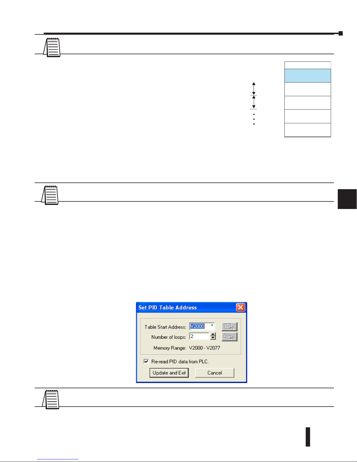
DL06 Micro PLC User Manual, 3rd Edition, Rev. D
8-19
Chapter 8: PID Loop Operation
1
2
3
4
5
6
7
8
9
10
11
12
13
14
A
B
C
D
1
2
3
4
5
6
7
8
9
10
11
12
13
14
A
B
C
D
NOTE: The DL06 CPU’s PID algorithm requires DirectSOFT Version 5.0 (or later) and firmware
version 2.1 (or later). See our website for more information: www.automationdirect.com.
The Loop Table contains data for only the number of loops that
are selected. The address for the table is stored in V7641. Each
loop configuration occupies 32 words (0 to 37 octal) in the loop
table.
For example, consider an application with 4 loops, and V2000
has been chosen as the starting location. The Loop Parameter
will occupy V2000 – V2037 for loop 1, V2040 – V2077 for
loop 2 and so on. Loop 4 occupies V2140 - V2177.
Determine the block of V-memory to be used for each
PID loop. Besides being the beginning of the PID parameter
memory block, the first address will be the start of loop 1 parameters. Remember, there are
32 words (0 to 37 octal) needed for each loop. Once you have determined the beginning
V-memory address to be used, you can setup and store the PID parameters either directly in
your RLL program or by the using PID Setup in DirectSOFT.
NOTE: Whether one or more loops are being setup, this block of V-memory will only be used for the
PID loop parameters, do not use this block of memory for anything else in your program.
Using DirectSOFT is the simplest way to setup the parameters. To setup the PID parameters,
the DL06 must be powered up and connected to the programming computer. The
parameters can only be entered in PID setup when the PLC is in the Program mode. Once
the parameters have been entered and saved for each loop, changes made through the PID
setup can be made, but only in Program Mode. You can type the beginning address in the
PID Table Address dialog found when the PID Setup is opened in DirectSOFT. This can
be seen in the diagram below. After the address has been entered, the memory range will
appear. Also, entering the number of PID loops (1 to 8) will set the total V-memory range
for the number of loops entered. After the V-memory address has been entered, the necessary
PID parameters for a basic loop operation for each loop can be setup with the dialogs made
available.
NOTE: Have an edited program open, then click on PLC > Setup > PID to access the Setup PID
dialog.
V–Memory
User Data
LOOP #1
V2000
32 words
LOOP #2
32 words
LOOP #3
32 words
LOOP #4
32 words
V2037
V2040
V2077
Page 98

DL06 Micro PLC User Manual, 3rd Edition, Rev. D
8-20
Chapter 8: PID Loop Operation
1
2
3
4
5
6
7
8
9
10
11
12
13
14
A
B
C
D
Loop Table Word Definitions
These are the loop parameters associated with each of the four loops available in the DL06.
The parameters are listed in the following table. The address offset is in octal, to help you
locate specific parameters in the loop table. For example, if a table begins at V2000, then the
location of the reset (integral) term is Addr+11, or V2011. Do not use the Word # (in the
first column) to calculate addresses.
1
2
3
4
5
6
7
8
9
10
11
12
13
14
A
B
C
D
Word # Address+Offset Description Format
Read
on-the-
fly***
1 Addr + 0 PID Loop Mode Setting 1 bits Yes
2 Addr + 1 PID Loop Mode Setting 2 bits Yes
3 Addr + 2 Setpoint Value (SP) word/binary Yes
4 Addr + 3 Process Variable (PV) word/binary Yes
5 Addr + 4 Bias (Integrator) Value word/binary Yes
6 Addr + 5 Control Output Value word/binary Yes
7 Addr + 6 Loop Mode and Alarm Status bits –
8 Addr + 7 Sample Rate Setting word/BCD Yes
9 Addr + 10 Gain (Proportional) Setting word/BCD Yes
10 Addr + 11 Reset (Integral) Time Setting word/BCD Yes
11 Addr + 12 Rate (Derivative) Time Setting word/BCD Yes
12 Addr + 13 PV Value, Low-low Alarm word/binary No*
13 Addr + 14 PV Value, Low Alarm word/binary No*
14 Addr + 15 PV Value, High Alarm word/binary No*
15 Addr + 16 PV Value, High-high Alarm word/binary No*
16 Addr + 17 PV Value, deviation alarm (YELLOW) word/binary No*
17 Addr + 20 PV Value, deviation alarm (RED) word/binary No*
18 Addr + 21 PV Value, rate-of-change alarm word/binary No*
19 Addr + 22 PV Value, alarm hysteresis setting word/binary No*
20 Addr + 23 PV Value, error deadband setting word/binary Yes
21 Addr + 24 PV low-pass filter constant word/BCD Yes
22 Addr + 25 Loop derivative gain limiting factor setting word/BCD No**
23 Addr + 26 SP value lower limit setting word/binary Yes
24 Addr + 27 SP value upper limit setting word/binary Yes
25 Addr + 30 Control output value lower limit setting word/binary No**
26 Addr + 31 Control output value upper limit setting word/binary No**
27 Addr + 32 Remote SP Value V-Memory Address Pointer word/hex Yes
28 Addr + 33 Ramp/Soak Setting Flag bit Yes
29 Addr + 34 Ramp/Soak Programming Table Starting Address word/hex No**
30 Addr + 35 Ramp/Soak Programming Table Error Flags bits No**
31 Addr + 36 PV auto transfer, channel number word/hex Yes
32 Addr + 37 Control output auto transfer, channel number word/hex Yes
* Read data only when alarm enable bit transitions from 0 to 1.
** Read data only on PLC Mode change.
*** Read on-the-fly means that the content of V-memory can be changed while the PID loop is in
operation.
Page 99
DL06 Micro PLC User Manual, 3rd Edition, Rev. D
8-21
Chapter 8: PID Loop Operation
1
2
3
4
5
6
7
8
9
10
11
12
13
14
A
B
C
D
PID Mode Setting 1 Bit Descriptions (Addr + 00)
The individual bit definitions of the PID Mode Setting 1 word (Addr+00) are listed in the
following table.
1
2
3
4
5
6
7
8
9
10
11
12
13
14
A
B
C
D
Bit PID Mode Setting 1 Description Read/Write Bit=0 Bit=1
0 Manual Mode Loop Operation request write – 01 request
1 Automatic Mode Loop Operation request write – 01 request
2 Cascade Mode Loop Operation request write – 01 request
3 Bumpless Transfer select write Mode I Mode II
4 Direct or Reverse-Acting Loop select write Direct Reverse
5 Position / Velocity Algorithm select write Position Velocity
6 PV Linear / Square Root Extract select write Linear Sq. root
7 Error Term Linear / Squared select write Linear Squared
8 Error Deadband enable write Disable Enable
9 Derivative Gain Limit select write Off On
10 Bias (Integrator) Freeze select write Off On
11 Ramp/Soak Operation select write Off On
12 PV Alarm Monitor select write Off On
13 PV Deviation alarm select write Off On
14 PV rate-of-change alarm select write Off On
15 Loop mode is independent from CPU mode when set write
Loop with CPU
mode
Loop Independent
of CPU mode
Page 100
DL06 Micro PLC User Manual, 3rd Edition, Rev. D
8-22
Chapter 8: PID Loop Operation
1
2
3
4
5
6
7
8
9
10
11
12
13
14
A
B
C
D
PID Mode Setting 2 Bit Descriptions (Addr + 01)
The individual bit definitions of the PID Mode Setting 2 word (Addr+01) are listed in the
following table.
NOTE 1: Bit 7 can be used to cancel Autotune mode by setting it to 0.
NOTE 2: If the value in bit 9 is 0, then the values in bits 0 and 1 are read. If the value in bit 9 is
1, then the values in bits 0 and 1 are not read, and bit 9 defines the data format (the range is
automatically unipolar).
NOTE 3: If the value in bit 10 is 0, then the values in bits 0, 1 and 9 define the input and output
ranges and data formats (the values in bits 11, 12, and 13 are not read). If the value in bit 10 is 1,
then the values in bits 0, 1, and 9 define only the input range and data format, and bits 11, 12, and
13 are read and define the output range and data format.
NOTE 4: If bit 10 has a value of 1 and bit 13 has a value of 0, then bits 11 and 12 are read and define
the output range and data format. If bit 10 and bit 13 each have a value of 1, then bits 11 and 12 are
not read, and bit 13 defines the data format, (the output range is automatically unipolar).
1
2
3
4
5
6
7
8
9
10
11
12
13
14
A
B
C
D
Bit PID Mode 2 Word Description Read/Write Bit=0 Bit=1
0
Input (PV) and Control Output Range Unipolar/Bipolar
select (See Notes 2 and 3)
write unipolar bipolar
1 Input/Output Data Format select (See Notes 2 and 3) write 12 bit 15 bit
2 Analog Input filter write off on
3 SP Input limit enable write disable enable
4 Integral Gain (Reset) units select write seconds minutes
5 Select Auto tune PID algorithm write closed loop open loop
6 Auto tune selection write PID PI only (rate = 0)
7
Auto tune start
(See Note 1)
read/write
auto tune
cancel/done
force start
8 PID Scan Clock (internal use) read – –
9
Input/Output Data Format 16-bit select
(See Notes 1 and 2)
write not 16 bit select 16 bit
10
Select separate data format for input and output
(See Notes 2, and 3)
write same format separate formats
11
Control Output Range Unipolar/Bipolar select
See Notes 2, and 3)
write unipolar bipolar
12 Output Data Format select (See Notes 2, and 3) write 12 bit 15 bit
13 Output data format 16-bit select (See Notes 2, and 3) write not 16 bit select16 bit
14–15 Reserved for future use – – –
 Loading...