

Page 1

WEG CFW100 AC DrivEs sEriAl
CommuniCAtions QuiCk-stArt GuiDE
NOTE: This Quick-Start guide is intended for the sole purpose of establishing
communications connections between WEG CFW100 AC Drives and AutomationDirect
programmable controllers, or between the CFW100 and the USB port of a personal
computer. Please refer to WEG CFW100 documents for specifications and instructions
for using the WEG CFW100 AC Drives.
T
able of ConTenTs
Communications Parameters Summary � � � � � � � � � � � � � � � � � � � � � � � � � � � � � � � �5–2
Summary – Serial Communication Parameters � � � � � � � � � � � � � � � � � � � � � � � � � � � � � � � 5–2
Explanation of Scaling/Count Frequency Command/Feedback � � � � � � � � � � � � � � � � � � �5–5
Connecting PC to CFW100 Using AutomationDirect Cable USB-485M� � � � � � � � � � � � � � �5–5
Connecting Communication Cables to CFW100 AC Drives � � � � � � � � � � � � � � � � � � � � �5–6
AutomationDirect PLCs as Modbus Master � � � � � � � � � � � � � � � � � � � � � � � � � � � � � �5–7
Communication Cable Connections � � � � � � � � � � � � � � � � � � � � � � � � � � � � � � � � � � � � � 5–7
RS-232C to RS-485 Conversion� � � � � � � � � � � � � � � � � � � � � � � � � � � � � � � � � � � � � � � � 5–8
AutomationDirect PLC Cable Connections � � � � � � � � � � � � � � � � � � � � � � � � � � � � � � � � � 5–9
AutomationDirect PLC Example Programs for WEG CFW100 AC Drive � � � � � � � � � � � � � � � � � � 5–12
CLICK PLC Example Program for WEG CFW100 AC Drive � � � � � � � � � � � � � � � � � � � � � � � � �5–12
Page 5–1CFW100 AC Drives Serial Communications Quick-Start Guide – 1st Edition-10 25 2019 prelim
Page 2
WEG CFW100 AC Drives Serial Communications Quick-Start Guide
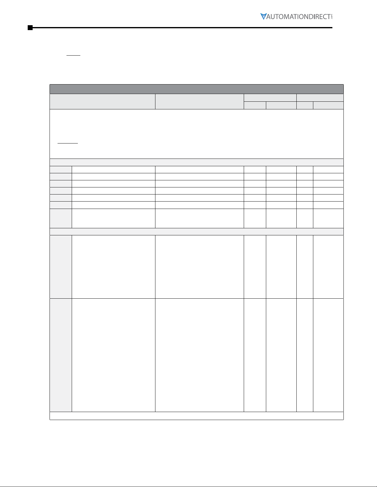
CommuniCations Parameters summary
A summary of the WEG CFW100 AC drives Communications Parameters is listed below.
NOTE: Refer to the WEG CFW100 Frequency Inverter Micro Mini Drives Programming Manual and the Modbus
RTU User’s Manual for a complete listing of all CFW100 AC drives parameters, including details and Modbus
addresses.
Summary – Serial CommuniCation ParameterS
WEG CFW100 Serial Communication Parameters Summary
Parameter
2
Range
1) To read parameters, use Function Code 3; To write parameters, use Function Code 6 or 16
2) ♦ indicates a parameter that can be changed only with a stopped motor
3) RO = Read Only
4) Modicon Modbus addressing for the CFW100 is 40000 + the Parameter Address;
Example: P222 Modicon Modbus address would be 40000 + 222 = 40222
5) Speed references and commands via Modbus RTU will always be Remote references; not Local
6) Baud rate in the PLC must match the baud rate in the AC drive (19200 bits/s)
General Parameters
P000
P001
P002
P003
P004
P005
♦P200
Access to Parameters 0 to 9999 1 0 40000
Speed Reference 0 to 9999 RO RO 1 40001
Output Speed (Motor) 0 to 9999 RO RO 2 40002
Motor Current 0�0 to 40�0 A RO RO 3 40003
DC Link Voltage (Ud) 0 to 524 V RO RO 4 40004
Output Frequency (Motor) 0�0 to 400�0 Hz RO RO 5 40005
0 = Inactive
Password
1 = Active
2 to 9999 = New Password
Parameters neccessary to communicate with the drive using module CFW-485
0 = Always Local
1 = Always Remote
2, 3 = not used
4 = DIx
♦P220
♦P222
LOC/REM Selection Source
REM Reference Selection
5)
5 = Serial/USB (LOC)
6 = Serial/USB (REM)
7, 8 = not used
9 = CO/DN/DP (LOC)
10 = CO/DN/DP (REM)
11 = SoftPLC
0 = HMI Keys
1 = AI1
2 = AI2
3 = not used
4 = FI
5 = AI1 + AI2 > 0
6 = AI1 + AI2
7 = E�P�
8 = Multispeed
9 = Serial/USB
10 = not used
11 = CO/DN/DP
12 = SoftPLC
13 = not used
14 = AI1 > 0
15 = AI2 > 0
16 = not used
17 = FI > 0
(table continued next page)
Setting Modbus Address
Comm Default
1 0 DC 40220
9 1 DE 40222
1
3
Hex Modicon
0 C8 40200
4
Page 5–2 CFW100 AC Drives Serial Communications Quick-Start Guide – 1st Edition
Page 3

WEG CFW100 AC Drives Serial Communications Quick-Start Guide
WEG CFW100 Serial Communication Parameters Summary1 – (continued)
Parameter
2
Range
1) To read parameters, use Function Code 3; To write parameters, use Function Code 6 or 16
2) ♦ indicates a parameter that can be changed only with a stopped motor
3) RO = Read Only
4) Modicon Modbus addressing for the CFW100 is 40000 + the Parameter Address;
Example: P222 Modicon Modbus address would be 40000 + 222 = 40222
5) Speed references and commands via Modbus RTU will always be Remote references; not Local
6) Baud rate in the PLC must match the baud rate in the AC drive (19200 bits/s)
0 = Forward
1 = Reverse
2, 3 = not used
4 = DIx
5 = Serial/USB (FWD)
♦P226
♦P227
♦P308
♦P310
♦P311
♦P312
P313
♦P314
P316
REM FWD/REV Selection
REM Run/Stop Selection
Serial Address 1 to 247 1 1 134 40308
Serial Baud Rate
Serial Interface Byte Configuration
Serial Protocol
Action for Comm Error
Serial Watchdog 0�0 to 999�0 0�0 0�0 13A 40314
Serial Interface Status
6)
6 = Serial/USB (REV)
7, 8 = not used
9 = CO/DN/DP (FWD)
10 = CO/DN/DP (REV)
11 = not used
12 = SoftPLC
0 = HMI Keys
1 = DIx
2 = Serial/USB
3 = not used
4 = CO/DN/DP
5 = SoftPLC
0 = 9600 bits/s
1 = 19200 bits/s
2 = 38400 bits/s
0 = 8 bits, np, 1 stop bit
1 = 8 bits, even, 1 stop bit
2 = 8 bits, odd, 1 stop bit
3 = 8 bits, np, 2 stop bits
4 = 8 bits, even, 2 stop bits
5 = 8 bits, odd, 2 stop bits
0, 1 = reserved
2 = Slave Modbus RTU
3, 4 = reserved
5 = Master Modbus RTU
0 = Inactive
1 = Ramp Stop
2 = General Disable
3 = Go to LOC
4 = LOC Keep Enable
5 = Cause Fault
0 = Inactive
1 = Active
2 = Watchdog Error
(table continued next page)
Setting Modbus Address
Comm Default
2 1 E3 40227
1 1 136 40310
1 1 137 40311
2 2 138 40312
1 1 139 40313
RO RO 13C 40316
3
Hex Modicon
4 E2 40226
4
Page 5–3 CFW100 AC Drives Serial Communications Quick-Start Guide – 1st Edition
Page 4

WEG CFW100 AC Drives Serial Communications Quick-Start Guide
WEG CFW100 Serial Communication Parameters Summary1 – (continued)
Parameter
2
Range
1) To read parameters, use Function Code 3; To write parameters, use Function Code 6 or 16
2) ♦ indicates a parameter that can be changed only with a stopped motor
3) RO = Read Only
4) Modicon Modbus addressing for the CFW100 is 40000 + the Parameter Address;
Example: P222 Modicon Modbus address would be 40000 + 222 = 40222
5) Speed references and commands via Modbus RTU will always be Remote references; not Local
6) Baud rate in the PLC must match the baud rate in the AC drive (19200 bits/s)
0 to FFFF (hex)
Bit 0 = reserved
Bit 1 = Run Command
Bit 2 = Fire Mode
Bits 3 and 4 = reserved
Bit 5 = 2nd Ramp
Bit 6 = Config� Status
P680
P681
P682
P683
Logical Status
Motor Speed in 13 bits 0 to FFFF (hex) RO RO 2A9 40681
Serial//USB Control
Serial/USB Speed Reference 0 to FFFF (hex) RO RO 2AB 40683
Bit 7 = Alarm
Bit 8 = Running
Bit 9 = Enabled
Bit 10 = Forward
Bit 11 = JOG
Bit 12 = Remote
Bit 13 = Undervoltage
Bit 14 = reserved
Bit 15 = Fault
0 to FFFF (hex)
Bit 0 = Ramp Enable
Bit 1 = General Enable
Bit 2 = Run Forward
Bit 3 = JOG Enable
Bit 4 = Remote
Bit 5 = 2nd Ramp
Bit 6 = reserved
Bit 7 = Fault Reset
Bit 8 to 15 = reserved
Setting Modbus Address
Comm Default
RO RO 2A8 40680
RO RO 2AA 40682
3
Hex Modicon
4
Page 5–4 CFW100 AC Drives Serial Communications Quick-Start Guide – 1st Edition
Page 5

WEG CFW100 AC Drives Serial Communications Quick-Start Guide
exPlanation of sCaling/Count frequenCy Command/feedbaCk
•
When using WEG CFW100 drives, speed/frequency is shown in counts� In order to convert to Hz/
rpm, it is needed to know that the Base Frequency (P403) is equivalent to 8192 (2^13)� Also, the
Motor Rated speed (P402) can be scaled using the same method�
•
Actual Frequency (P681) and Command Frequency (P683) can be calculated using that ratio�
•
For instance: P681 = 2048(dec)�
•
Freq = 2048*60�00/8192 = 15�00 Hz
•
RPM = 2048*1740/8192 = 435�00 rpm
ConneCting PC to CfW100 using automationdireCt Cable usb-485m
An AutomationDirect cable, part number USB-485M, provides a quick and easy method of
communicating to a WEG CFW100 AC Drive from a PC which has WEG CFW-WPS software installed.
NOTE: Refer to the WEG WPS Software User Manual for information and instructions regarding using the WPS
software to configure CFW100 AC Drives.
AutomationDirect USB-485M
Connector
6 RS485 = A (-)
7 RS485 = B (+)
8 GND
9 Shield
10 GND
To
RS-485
Port
Page 5–5 CFW100 AC Drives Serial Communications Quick-Start Guide – 1st Edition
Page 6

WEG CFW100 AC Drives Serial Communications Quick-Start Guide
Figure A2: C FW100 -CRS485 dimensi ons in mm [i n] and conn ectors l ocation
Ref (0 V) Ref (0 V)
Shield
6 7 8 9 10
Shield
B B
A A
Figure A3: Example of connection of the a ccessor y to the RS48 5 networ k
1 SAFETY INFORMATION
1.1 SAFETY WARNI NGS
NOTE!
Only use the RS485 module (CF W100-C RS485) on WEG CF W100
series inve rter s.
It is re commend ed read ing th e CFW100 user ’s manual before
installing or operating this acce ssor y.
The content of this guide provide s important info rmation for the full
under standing and proper oper ation of this module.
1.2 PRE LIMINARY RECOMMENDATIONS
ATTENTION!
Always disconnect the gene ral power supply before connecting or
disconnec ting the accessories of the CFW100 fre quency inver ter.
Wait for at least 10 minute s for the full discharge of th e inverter.
5 CONFIGURATIONS
The RS485 interf ace connections mu st be done on the conn ector as per Table 1.
Table 1: Conne ctor sign als of the R S485 inte rface
Conn ector Desc riptio n
6 RS 485-B RS485 ( Terminal B)
7 RS485-A RS485 ( Terminal A)
8 0V Refere nce 0V
9 PE Grounding connection
10 – –
The location of the DIP sw itch to select the RS485 network term ination can b e
better viewed in Figure A2 and it must be configure as per Table 2. . Figure A3
shows a connection example of the CFW100-CRS 485 accessory to a RS485
network. The connection compli es with the directions of the use r's manual of the
Modbus RTU for the CF W100.
Table 2: C onfigur ation of th e switche s to configure t he RS485
Comun icati on Switch Swit ch Set tin g Opti on
RS485
S1
(*)
S1.1 = OFF and S1.2 = OFF RS 485 terminat ion off
S1.1 = ON and S1.2 = ON
RS485 ter minati on on
(**)
(*) Any other combinat ion of the sw itches is n ot allowed.
(**) It is recommend ed to use thi s terminatio n with cable s longer than 3 m.
The CFW100-CRS485 m odule has the ne cessar y resources to perform set ting,
command and m onitor ing of the inver ter by mean s of the WPS sof tware - WEG
Programming Suite (www.automationdirect.com). For further detai
ls, refer to chapter
7 of the use r's manua l of the CF W100.
IMPORTANT NOTE!
The mini USB connector (se e Figure A2) is used for communicati on
with the C FW100-KHMIR k it only.
The use of the mini USB connector for other connecti ons is n ot
permitted.
For PC to USB Connections to the CFW100 use the CFW100-CUSB
Module only.
CFW100-CRS485
Please read “IMPORTANT NOTE”!
Lorem ipsum
ConneCting CommuniCation Cables to CfW100 aC drives
The CFW100-CRS485 drive communication module includes a DIP switch that will switch in a 120Ω
terminating resistor for the RS-485 network.
The CFW100 serial communication port is an RS-485 input. Please note that terminals A(-) and B(+) are
shared with the USB connector. CFW100 to CFW100 serial connections can be accomplished with standard
RS-485 cable (L19827-1 or similar). RS-232 signals can be converted to RS-485 by using a separate converter
(see the FA-ISOCON drawings on page 5–8).
CFW100-CrS485 Serial CommuniCationS module
WARNING: Do NoT use ThIs usB poRT foR ANy pC CoNNeCTIoNs foR ANy ReAsoN, As IT mAy veRy Well DAmAGe The
DRIve AND youR pC. IT Is foR CoNNeCTIoN of The RemoTe KeypAD KIT CfW100-KhmIR oNly.
Page 5–6 CFW100 AC Drives Serial Communications Quick-Start Guide – 1st Edition
Recommended RS-485 cable: Belden 9842, AutomationDirect L19954 series, or equivalent.
Page 7

WEG CFW100 AC Drives Serial Communications Quick-Start Guide
automationdireCt PlCs as modbus master
CommuniCation Cable ConneCtionS
Serial Modbus-capable AutomationDirect PLCs can communicate with CFW100 drives which have
an optional communication card installed.
Serial Modbus control is easier to accomplish from a PLC that supports dedicated Modbus
messaging. [Older PLCs may require programming to construct the Modbus strings.] We
recommend PLCs with dedicated Modbus serial commands: CLICK (with RS-485 ports), P1000,
P2000, P3000, BRX/Do-more, DirectLogic (DL06 or D2-260). Other PLC-Drive connectivity is
possible: Please refer to the “Typical ADC PLC to CFW100 Serial Connectivity Matrix” below.
Typical ADC PLC to WEG CFW100 RS-485 Serial Communications Connectivity
Typical ADC PLC to WEG CFW100 RS-485 Serial Communications Connectivity Matrix
Recommended PLC Connectivity
PLC Port # Port Type Port Type
CLICK
D2-260
DL06
BRX/Do-more
Do-more H2-DM1
P2-550
P3-530
P3-550
P3-550E
Other PLC Connectivity
D2-250-1
D4-450/D4-454
DL05
DL06 + DCM
Do-more H2-DM1 + H2-SERIO-4
Do-more T1H-DM1
P2-SCM
P3-SCM
3 3 screw terminals RS-485 L19954 cable
2 HD15 RS-485 D2-DSCBL-2
2 HD15 RS-485 D2-DSCBL-2
RS-485 3 screw terminals RS-485 L19954 cable
RS-232 RJ12 RS-232 to RS-485
RS-485 3 screw terminals RS-485 L19954 cable
RS-485 3 screw terminals RS-485 L19954 cable
RS-485 3 screw terminals RS-485 L19954 cable
RS-485 3 screw terminals RS-485 L19954 cable
2 HD15 RS-485 D2-DSCBL-2
1 DB25 RS-232 to RS-485
2 RJ12 RS-232 to RS-485
2 HD15 RS-485 D2-DSCBL-2
3 5 screw terminals RS-485 L19954 cable
RS-232 RJ12 RS-232 to RS-485
4 4 screw terminals RS-485 L19954 cable
4 4 screw terminals RS-485 L19954 cable
Communication Direct Cable
– –
FA-ISOCON with
L19954 cable
FA-ISOCON with
L19954 cable
FA-ISOCON with
L19954 cable
FA-ISOCON with
L19954 cable
CFW100
CFW100-
CRS485
screw
terminals
A(-)
B(+)
Ref(0V)
Page 5–7 CFW100 AC Drives Serial Communications Quick-Start Guide – 1st Edition
Page 8

WEG CFW100 AC Drives Serial Communications Quick-Start Guide
FA-ISOCON RJ-12 Serial Comm Port A
6: Signal Ground
rS-232C to rS-485 ConverSion
An RS-485 network cable can span up to 1000 meters (4000feet). However, many
AutomationDirect PLCs have only RS-232C communication ports and require an FA-ISOCON
(RS-232C to RS-422/485 network adapter) in order to make an RS-485 connection.
If an FA-ISOCON module is used, set the module DIP switches as required.
Refer to the FA-ISOCON manual for more detailed information.
FA-ISOCON Switch Settings:
•
S21–S23: OFF, ON, ON (19200 baud)
•
S24–S27: OFF (Automatic Network Transmit Enable)
•
Terminate: ON (end of run term resistors)
•
Bias (2): ON (end of run bias resistors)
•
1/2 DPX (2): ON (RS-485 TXD/RXD jumpers)
Helpful Hint: Some applications require that the FA-ISOCON
baud rate is set faster than the drive/network baud rate.
FA-ISOCON Wiring
RS-232 to RS-485 Conversion Wiring Schematic
C
+V
TXD
RXD
CTS
RTS
[CFW100 has a built-in 120Ω terminating resistor controllable by switch SW5 above the I/O terminal strip]
3 RXD
4 TXD
2 CTS
6 GNDGND
A
FA-ISOCON
RS-232 to RS-485 converter with ANTE
Connect shield
to signal ground
at one end only
D
COM A
TXD +
TXD RXD RXD +
COM B
120Ω Termination Resistor at both ends of network
[FA-ISOCON has a built-in terminating resistor
controllable by switch settings]
24VDC +
24VDC -
Ref (0V)
Ref (0V)
120Ω Termination Resistor at both ends of network
RS-232 Input Port
16
CFW100-CRS485
Comm Terminals
B (+)
A (-)
B (+)
A (-)
6
Lo
7
8
Node 1
CFW100-CRS485
Comm Terminals
6
7
8
Node 2
1: Signal Ground
2: CTS (input)
3: RXD (input)
4: TXD (output)
5: +5VDC in
For information regarding configuration of AutomationDirect PLCs or other PLCs, please refer to
the applicable PLC user manual for your application.
Page 5–8 CFW100 AC Drives Serial Communications Quick-Start Guide – 1st Edition
Page 9

WEG CFW100 AC Drives Serial Communications Quick-Start Guide
automationdireCt PlC Cable ConneCtionS
CliCK SerieS Port 3 via rS-485
6
7
8
9
Note: Use the above wiring diagram to make your own cable. We recommend AutomationDirect part number L19954-1 shielded cable or equivalent.
Use 120 ohm termination resistor on each end. CRS485 has built-in termination that can be enabled by DIP switches.
Connector
6 RS485=B (+)
7 RS485=A (–)
8 GND
9 Shield
10 –
Page 5–9 CFW100 AC Drives Serial Communications Quick-Start Guide – 1st Edition
Page 10

WEG CFW100 AC Drives Serial Communications Quick-Start Guide
direCtlogiC SerieS d2-250-1, d2-260, dl06 Port 2 via rS-485
AutomationDirect D2-250-1, D2-260 or DL06 Port 2
6
7
8
9
e connection above can be accomplished with AutomationDirect part number ZL-CMA15L
connector and L19954-1 shielded cable or equivalent. Use termination jumper of ZL-CMA15L
and termination DIP switches on last CRS485.
Connector
6 RS485=B (+)
7 RS485=A (–)
8 GND
9 Shield
10 –
do-more brX SerieS via rS-485
AutomationDirect D0-more BRX CPU
Connector
6
7
8
9
Note: Use the above wiring diagram to make your own cable. We recommend AutomationDirect part number L19954-1 shielded cable or equivalent.
Use 120 ohm termination resistor on each end. CRS485 has built-in termination that can be enabled by DIP switches.
Connector
6 RS485=B (+)
6 RS485=B (+)
7 RS485=A (-)
7 RS485=A (-)
8 GND
8 GND
9 Shield
9 Shield
10 –
10 –
Page 5–10 CFW100 AC Drives Serial Communications Quick-Start Guide – 1st Edition
Page 11

WEG CFW100 AC Drives Serial Communications Quick-Start Guide
ProduCtivity SerieS P1 via rS-485
AutomationDirect Productivity Series P1
Connector
Connector
6 RS485=B (+)
6 RS485=B (+)
7 RS485=A (-)
7 RS485=A (-)
8 GND
8 GND
9 Shield
9 Shield
10 –
10 –
RS-485
6
7
8
9
Note: Use the above wiring diagram to make your own cable. We recommend AutomationDirect part number L19954-1 shielded cable or equivalent.
Use 120 ohm termination resistor on each end. CRS485 has built-in termination that can be enabled by DIP switches.
ProduCtivity SerieS P2/P3 via rS-485
AutomationDirect Productivity Series P2/P3
Connector
6
7
8
9
Note: Use the above wiring diagram to make your own cable. We recommend AutomationDirect part number L19954-1 shielded cable or equivalent.
Use 120 ohm termination resistor on each end. CRS485 has built-in termination that can be enabled by DIP switches.
Connector
6 RS485=B (+)
6 RS485=B (+)
7 RS485=A (-)
7 RS485=A (-)
8 GND
8 GND
9 Shield
9 Shield
10 –
10 –
Page 5–11 CFW100 AC Drives Serial Communications Quick-Start Guide – 1st Edition
Page 12

WEG CFW100 AC Drives Serial Communications Quick-Start Guide
automationdireCt PlC eXamPle ProgramS For Weg CFW100 aC drive
Example programs for various AutomationDirect PLCs are available for free download from
AutomationDirect: https://support.automationdirect.com/examples.html.
Also, an example CLICK PLC ladder diagram is show in the following section.
CliCK PlC eXamPle Program For Weg CFW100 aC drive
ThIs INfoRmATIoN pRovIDeD By AuTomATIoNDIReCT.Com TeChNICAl suppoRT Is
pRovIDeD “As Is” WIThouT ANy GuARANTee of ANy KIND.
These DoCumeNTs ARe pRovIDeD By ouR TeChNICAl suppoRT DepARTmeNT To AssIsT oTheRs. We Do
NoT GuARANTee ThAT The DATA Is suITABle foR youR pARTICulAR ApplICATIoN, NoR Do We Assume ANy
RespoNsIBIlITy foR Them IN youR ApplICATIoN.
CLICK PLC Example Program for WEG CFW100 AC Drive
1
(program continued next page)
Page 5–12 CFW100 AC Drives Serial Communications Quick-Start Guide – 1st Edition
Page 13

WEG CFW100 AC Drives Serial Communications Quick-Start Guide
CLICK PLC Example Program for WEG CFW100 AC Drive (continued)
(program continued next page)
Page 5–13 CFW100 AC Drives Serial Communications Quick-Start Guide – 1st Edition
Page 14

WEG CFW100 AC Drives Serial Communications Quick-Start Guide
CLICK PLC Example Program for WEG CFW100 AC Drive (continued)
This rung reads STATUS registers from Drive #1
(Modbus address 400681=Status word)
(Modbus address 400682=Output frequency in counts. 8192=60Hz)
This rung writes control register and Frq to Drive #1
Modbus address 400683=Control word
For Run command must write value 3: [Bit1:ON+Bit0:ON]
Modbus address 400684=Freq Counts. 8192=60Hz
(program continued next page)
Page 5–14 CFW100 AC Drives Serial Communications Quick-Start Guide – 1st Edition
Page 15

WEG CFW100 AC Drives Serial Communications Quick-Start Guide
CLICK PLC Example Program for WEG CFW100 AC Drive (continued)
This rung reads STATUS registers from Drive #2
(Modbus address 400681=Status word)
(Modbus address 400682=Output frequency in counts. 8192=60Hz.
Scaling Drive #1 freq (counts) to 0.01 Hz
In this example Base Freq=60Hz. This is equal to 8192 counts 2^13)
In order to convert to Hz: multiply by 60 and divide by 8192.
(program continued next page)
Page 5–15 CFW100 AC Drives Serial Communications Quick-Start Guide – 1st Edition
Page 16

WEG CFW100 AC Drives Serial Communications Quick-Start Guide
CLICK PLC Example Program for WEG CFW100 AC Drive (continued)
Scaling Drive#1 freq (Hz) to counts:
In this example Base Freq=60Hz. This is equal to 8192 counts (2^13)
In order to convert to counts: multiply by 8192 and divide by 60Hz.
Scaling Drive#2 freq (counts) to 0.01Hz:
In this example Base Freq=60Hz. This is equal to 8192 counts (2^13)
In order to convert to Hz: multiply by 60Hz and divide by 8192.
Scaling Drive#2 freq (Hz) to counts
In this example Base Freq=60Hz. This is equal to 8192 counts (2^13)
In order to convert to counts: multiply by 8192 and divide by 60Hz.
Page 5–16 CFW100 AC Drives Serial Communications Quick-Start Guide – 1st Edition
 Loading...