

Page 1

Terminator Installation
and I/O Manual
Manual Number: T1K-INST-M
Page 2

~
WARNING ~
Thank you for purchasing automation equipment from Automationdirect.com®, doing business as,
AutomationDirect. We want your new automation equipment to operate safely. Anyone who installs or
uses this equipment should read this publication (and any other relevant publications) before installing or
operating the equipment.
To minimize the risk of potential safety problems, you should follow all applicable local and national
codes that regulate the installation and operation of your equipment. These codes vary from area to area
and usually change with time. It is your responsibility to determine which codes should be followed, and
to verify that the equipment, installation, and operation is in compliance with the latest revision of these
codes.
At a minimum, you should follow all applicable sections of the National Fire Code, National Electrical
Code, and the codes of the National Electrical Manufacturer’s Association (NEMA). There may be local
regulatory or government offices that can also help determine which codes and standards are necessary for
safe installation and operation.
Equipment damage or serious injury to personnel can result from the failure to follow all applicable
codes and standards. We do not guarantee the products described in this publication are suitable for
your particular application, nor do we assume any responsibility for your product design, installation, or
operation.
Our products are not fault-tolerant and are not designed, manufactured or intended for use or resale as
on-line control equipment in hazardous environments requiring fail-safe performance, such as in the
operation of nuclear facilities, aircraft navigation or communication systems, air traffic control, direct life
support machines, or weapons systems, in which the failure of the product could lead directly to death,
personal injury, or severe physical or environmental damage (“High Risk Activities”). AutomationDirect
specifically disclaims any expressed or implied warranty of fitness for High Risk Activities.
For additional warranty and safety information, see the Terms and Conditions section of our catalog.
If you have any questions concerning the installation or operation of this equipment, or if you need
additional information, please call us at 770-844-4200.
This publication is based on information that was available at the time it was printed. At
AutomationDirect we constantly strive to improve our products and services, so we reserve the right to
make changes to the products and/or publications at any time without notice and without any obligation.
This publication may also discuss features that may not be available in certain revisions of the product.
Trademarks
This publication may contain references to products produced and/or offered by other companies. The
product and company names may be trademarked and are the sole property of their respective owners.
AutomationDirect disclaims any proprietary interest in the marks and names of others.
Copyright 2020, Automationdirect.com® Incorporated
No part of this manual shall be copied, reproduced, or transmitted in any way without the prior, written
consent of Automationdirect.com® Incorporated. AutomationDirect retains the exclusive rights to all
information included in this document.
All Rights Reserved
Page 3

~ ADVERTENCIA ~
Gracias por comprar equipo de automatización de Automationdirect.com®. Deseamos que su nuevo equipo
de automatización opere de manera segura. Cualquier persona que instale o use este equipo debe leer esta
publicación (y cualquier otra publicación pertinente) antes de instalar u operar el equipo.
Para reducir al mínimo el riesgo debido a problemas de seguridad, debe seguir todos los códigos de seguridad
locales o nacionales aplicables que regulan la instalación y operación de su equipo. Estos códigos varian de
área en área y usualmente cambian con el tiempo. Es su responsabilidad determinar cuales códigos deben ser
seguidos y verificar que el equipo, instalación y operación estén en cumplimiento con la revisión mas reciente
de estos códigos.
Como mínimo, debe seguir las secciones aplicables del Código Nacional de Incendio, Código Nacional Eléctrico,
y los códigos de (NEMA) la Asociación Nacional de Fabricantes Eléctricos de USA. Puede haber oficinas de
normas locales o del gobierno que pueden ayudar a determinar cuales códigos y normas son necesarios para una
instalación y operación segura.
Si no se siguen todos los códigos y normas aplicables, puede resultar en daños al equipo o lesiones serias a
personas. No garantizamos los productos descritos en esta publicación para ser adecuados para su aplicación
en particular, ni asumimos ninguna responsabilidad por el diseño de su producto, la instalación u operación.
Nuestros productos no son tolerantes a fallas y no han sido diseñados, fabricados o intencionados para uso
o reventa como equipo de control en línea en ambientes peligrosos que requieren una ejecución sin fallas,
tales como operación en instalaciones nucleares, sistemas de navegación aérea, o de comunicación, control de
tráfico aéreo, máquinas de soporte de vida o sistemas de armamentos en las cuales la falla del producto puede
resultar directamente en muerte, heridas personales, o daños físicos o ambientales severos (“Actividades de Alto
Riesgo”). Automationdirect.com específicamente rechaza cualquier garantía ya sea expresada o implicada
para actividades de alto riesgo.
Para información adicional acerca de garantía e información de seguridad, vea la sección de Términos
y Condiciones de nuestro catálogo. Si tiene alguna pregunta sobre instalación u operación de este equipo, o
si necesita información adicional, por favor llámenos al número 770-844-4200 en Estados Unidos.
Esta publicación está basada en la información disponible al momento de impresión. En Automationdirect.
com nos esforzamos constantemente para mejorar nuestros productos y servicios, así que nos reservamos el
derecho de hacer cambios al producto y/o a las publicaciones en cualquier momento sin notificación y sin
ninguna obligación. Esta publicación también puede discutir características que no estén disponibles en ciertas
revisiones del producto.
Marcas Registradas
Esta publicación puede contener referencias a productos producidos y/u ofrecidos por otras compañías. Los nombres de las
compañías y productos pueden tener marcas registradas y son propiedad única de sus respectivos dueños. Automationdirect.com,
renuncia cualquier interés propietario en las marcas y nombres de otros.
PROPIEDAD LITERARIA 2020, AUTOMATIONDIRECT.COM® INCORPORATED
No se permite copiar, reproducir, o transmitir de ninguna forma ninguna parte de este manual sin previo consentimiento por escrito
de Automationdirect.com
este documento. Los usuarios de este equipo pueden copiar este documento solamente para instalar, configurar y mantener el equipo
correspondiente. También las instituciones de enseñanza pueden usar este manual para propósitos educativos.
®
Incorprated. Automationdirect.com retiene los derechos exclusivos a toda la información incluida en
Todos los derechos reservados
Page 4

~ AVERTISSEMENT
Nous vous remercions d’avoir acheté l’équipement d’automatisation de Automationdirect.com®, en faisant des
affaires comme, AutomationDirect. Nous tenons à ce que votre nouvel équipement d’automatisation fonctionne en
toute sécurité. Toute personne qui installe ou utilise cet équipement doit lire la présente publication (et toutes les
autres publications pertinentes) avant de l’installer ou de l’utiliser.
Afin de réduire au minimum le risque d’éventuels problèmes de sécurité, vous devez respecter tous les codes locaux
et nationaux applicables régissant l’installation et le fonctionnement de votre équipement. Ces codes diffèrent d’une
région à l’autre et, habituellement, évoluent au fil du temps. Il vous incombe de déterminer les codes à respecter et
de vous assurer que l’équipement, l’installation et le fonctionnement sont conformes aux exigences de la version la
plus récente de ces codes.
Vous devez, à tout le moins, respecter toutes les sections applicables du Code national de prévention des incendies,
du Code national de l’électricité et des codes de la National Electrical Manufacturer’s Association (NEMA). Des
organismes de réglementation ou des services gouvernementaux locaux peuvent également vous aider à déterminer
les codes ainsi que les normes à respecter pour assurer une installation et un fonctionnement sûrs.
L’omission de respecter la totalité des codes et des normes applicables peut entraîner des dommages à l’équipement
ou causer de graves blessures au personnel. Nous ne garantissons pas que les produits décrits dans cette publication
conviennent à votre application particulière et nous n’assumons aucune responsabilité à l’égard de la conception, de
l’installation ou du fonctionnement de votre produit.
Nos produits ne sont pas insensibles aux défaillances et ne sont ni conçus ni fabriqués pour l’utilisation ou la revente
en tant qu’équipement de commande en ligne dans des environnements dangereux nécessitant une sécurité absolue,
par exemple, l’exploitation d’installations nucléaires, les systèmes de navigation aérienne ou de communication, le
contrôle de la circulation aérienne, les équipements de survie ou les systèmes d’armes, pour lesquels la défaillance du
produit peut provoquer la mort, des blessures corporelles ou de graves dommages matériels ou environnementaux
(«activités à risque élevé»). La société AutomationDirect nie toute garantie expresse ou implicite d’aptitude à
l’emploi en ce qui a trait aux activités à risque élevé.
Pour des renseignements additionnels touchant la garantie et la sécurité, veuillez consulter la section Modalités et
conditions de notre documentation. Si vous avez des questions au sujet de l’installation ou du fonctionnement de cet
équipement, ou encore si vous avez besoin de renseignements supplémentaires, n’hésitez pas à nous téléphoner au
770-844-4200.
Cette publication s’appuie sur l’information qui était disponible au moment de l’impression. À la société
AutomationDirect, nous nous efforçons constamment d’améliorer nos produits et services. C’est pourquoi nous
nous réservons le droit d’apporter des modifications aux produits ou aux publications en tout temps, sans préavis ni
quelque obligation que ce soit. La présente publication peut aussi porter sur des caractéristiques susceptibles de ne
pas être offertes dans certaines versions révisées du produit.
~
Marques de commerce
La présente publication peut contenir des références à des produits fabriqués ou offerts par d’autres entreprises. Les
désignations des produits et des entreprises peuvent être des marques de commerce et appartiennent exclusivement à
leurs propriétaires respectifs. AutomationDirect nie tout intérêt dans les autres marques et désignations.
Copyright 2020, Automationdirect.com® Incorporated
Nulle partie de ce manuel ne doit être copiée, reproduite ou transmise de quelque façon que ce soit sans le
consentement préalable écrit de la société Automationdirect.com® Incorporated. AutomationDirect conserve les
droits exclusifs à l’égard de tous les renseignements contenus dans le présent document.
Tous droits réservés
Page 5
TerminaTor insTallaTion
and I/O Manual
Please include the Manual Number and the Manual Issue, both shown below,
when communicating with Technical Support regarding this publication.
Manual Number: T1K-INST-M
Issue: 3rd Edition, Rev. C
Issue Date: 08/20
Edition/Rev Date Publication History
First Edition 11/00 Original issue
Rev. A 02/01 Added new module and minor corrections
Rev. B 07/01 Added new modules
Rev. C 04/02 Added new modules and minor corrections
Rev. D 12/02 Added new module and general updates
Rev. E 04/03 Added new module and added Class 1, Division 2, Zone 2 Approval
2nd Edition 09/03 Added new module and minor corrections
Rev. A 09/04 Added new modules and minor corrections
3rd Edition 05/13 Converted manual from Interleaf to QuarkXpress and made minor corrections
Rev. A 10/16 Added T1F-16TMST thermistor input module
Rev. B 01/18 Added Module Control Byte examples (4-21 to 4-24). General updates.
Rev. C 08/20 T1H-PBC discontinued, added notes to Chapter 3 accordingly.
Page 6

Table of ConTenTs
Chapter 1 - Getting Started
About This Manual .................................................................................................. 1-10
The Purpose of this Manual .................................................................................... 1-10
Supplemental Manuals ........................................................................................... 1-10
Technical Support................................................................................................... 1-10
Conventions Used .................................................................................................... 1-11
Key Topics for Each Chapter ................................................................................... 1-11
Terminator I/O Base Controllers ............................................................................. 1-12
Terminator I/O System Components ...................................................................... 1-13
Power Supplies ....................................................................................................... 1-13
I/O Modules ........................................................................................................... 1-13
Chapter 2 - Installation and Wiring
Safety Guidelines ..................................................................................................... 2-15
Plan for Safety ........................................................................................................ 2-15
Three Levels of Protection ...................................................................................... 2-16
Emergency Stops .................................................................................................... 2-16
Emergency Power Disconnect ................................................................................ 2-17
Orderly System Shutdown ...................................................................................... 2-17
Class 1, Division 2, Zone 2 Approval ...................................................................... 2-17
Mounting Guidelines ............................................................................................... 2-18
Dimensions ............................................................................................................ 2-18
Panel Mounting and Layout ................................................................................... 2-19
Enclosures .............................................................................................................. 2-20
Environmental Specifications .................................................................................. 2-21
Power ..................................................................................................................... 2-21
Agency Approvals ................................................................................................... 2-21
Page 7

Table of Contents
Assembling the Components .................................................................................. 2-22
Assembling the I/O Modules and Bases .................................................................. 2-22
Mounting the Components on DIN Rail ................................................................. 2-22
Connecting the Components on the DIN Rail ........................................................ 2-23
Removing I/O Modules from the Base .................................................................... 2-23
Multiple Power Supplies / Local Expansion Configurations .................................. 2-24
Multiple Power Supply Configuration ..................................................................... 2-24
Example Using T1K-10CBL and T1K-10CBL-1 Expansion Cables ............................. 2-24
Example Using T1K-05CBL-RR-1 and T1K-05CBL-LL Expansion Cables ................... 2-25
Example Using T1K-10CBL and T1K-05CBL-RR-1 Expansion Cables ........................ 2-26
Example Using T1K-05CBL-RR-1 Expansion Cables ................................................. 2-27
Power Supply Wiring Guidelines ............................................................................. 2-28
Power Wiring ......................................................................................................... 2-28
Chapter 3 - I/O Wiring and Specifications
I/O Wiring Strategies ................................................................................................ 3-3
Terminator I/O System Isolation Boundaries ............................................................. 3-3
Powering I/O Circuits with the Auxiliary Supply ....................................................... 3-4
Powering I/O Circuits Using Separate Supplies ......................................................... 3-5
Sinking / Sourcing Concepts .................................................................................... 3-6
I/O “Common” Terminal Concepts .......................................................................... 3-7
Connecting DC I/O to Solid State Field Devices ....................................................... 3-8
Solid State Input Sensors .......................................................................................... 3-8
Solid State Output Loads .......................................................................................... 3-8
Relay Output Guidelines ......................................................................................... 3-10
Relay Outputs - Transient Suppression for Inductive Loads in a Control System...... 3-10
I/O Modules Position, Wiring and Specifications ................................................... 3-15
Multiple Power Supply Configuration ..................................................................... 3-15
Overview of I/O Expansion Configurations ............................................................. 3-16
Types of Modules Available for the Terminator System ........................................... 3-17
Discrete Module Status Indicators .......................................................................... 3-17
Color Coding of I/O Modules ................................................................................. 3-17
Wiring the I/O Module Bases .................................................................................. 3-18
Selecting Internal 24VDC Power Supply ................................................................. 3-19
Using Internal 24VDC Base Power .......................................................................... 3-19
Using Internally Bussed 24VDC (T1K-08ND3, T1K-16ND3 only) ............................ 3-19
Terminator Installation and I/O Manual, 3rd Edition, Rev. C
ii
Page 8

Table of Contents
External 24VDC Wiring Options ............................................................................. 3-20
Using T1K-01AC for External 24VDC Power ........................................................... 3-20
Using an External 24VDC Power Supply ................................................................. 3-20
I/O Wiring Checklist ............................................................................................... 3-21
Output Module Fusing ........................................................................................... 3-21
I/O Module Hot Swap Feature ................................................................................ 3-22
Hot Swap: I/O Module Replacement ...................................................................... 3-22
Outputs Enable / Disable Switch ............................................................................ 3-22
Check External 24VDC Wiring Before Hot Swapping .............................................. 3-22
Calculating the Power Budget ................................................................................ 3-23
Managing the Power Resource ............................................................................... 3-23
Power Supply Specifications ................................................................................... 3-23
Module Power Requirements .................................................................................. 3-24
Power Budget Calculation Example ........................................................................ 3-25
Power Budget Worksheet ....................................................................................... 3-26
I/O Specification Terms ........................................................................................... 3-27
Inputs or Outputs Per Module ................................................................................ 3-27
Commons Per Module ........................................................................................... 3-27
Input Voltage Range ............................................................................................... 3-27
Output Voltage Range ............................................................................................ 3-27
Peak Voltage ........................................................................................................... 3-27
AC Frequency ......................................................................................................... 3-27
ON Voltage Level ................................................................................................... 3-27
OFF Voltage Level ................................................................................................... 3-27
Input impedance .................................................................................................... 3-27
Input Current ......................................................................................................... 3-27
Minimum ON Current ............................................................................................ 3-27
Maximum OFF Current .......................................................................................... 3-27
Minimum Load....................................................................................................... 3-27
External DC Required ............................................................................................. 3-27
ON Voltage Drop ................................................................................................... 3-28
Maximum Leakage Current .................................................................................... 3-28
Maximum Inrush Current ....................................................................................... 3-28
Base Power Required .............................................................................................. 3-28
OFF to ON Response .............................................................................................. 3-28
Terminator Installation and I/O Manual, 3rd Edition, Rev. C
iii
iii
Page 9

Table of Contents
ON to OFF Response .............................................................................................. 3-28
Terminal Type ......................................................................................................... 3-28
Status Indicators ..................................................................................................... 3-28
Weight ................................................................................................................... 3-28
Fuses ...................................................................................................................... 3-28
T1K-01AC, T1K-01DC Power Supply ....................................................................... 3-29
Dimensions ............................................................................................................ 3-30
T1H-EBC Ethernet Base Controller (Obsolete) ....................................................... 3-31
Dimensions ............................................................................................................ 3-32
T1K-EBC Ethernet Port Pin-out ............................................................................... 3-32
T1K-EBC Serial Port Pin-out .................................................................................... 3-32
T1H-EBC100 Ethernet Base Controller .................................................................... 3-33
Dimensions ............................................................................................................ 3-34
T1K-EBC100 Ethernet Port Pin-out ......................................................................... 3-34
T1K-EBC100 Serial Port Pin-out .............................................................................. 3-34
T1K-DEVNETS .......................................................................................................... 3-35
T1K-DEVNETS Serial Port Pin-out ............................................................................ 3-36
Dimensions ............................................................................................................ 3-36
T1K-DEVNETS DIP Switch Settings ......................................................................... 3-36
T1K-MODBUS Base Controller ................................................................................ 3-37
Dimensions ............................................................................................................ 3-38
T1K-MODBUS DIP Switch Settings .............................................................. 3-38
T1K-RSSS Remote I/O Base Controller ................................................................... 3-39
Dimensions ............................................................................................................ 3-40
T1K-RSSS DIP Switch Settings................................................................................. 3-40
T1K-RSSS Serial Port Pin-out ................................................................................... 3-40
T1H-PBC Profibus Base Controller .......................................................................... 3-41
Dimensions ............................................................................................................ 3-42
T1H-PBC Port Pin-out ............................................................................................. 3-42
T1K-08ND3 DC Input ............................................................................................... 3-43
Wiring & Dimensions ............................................................................................. 3-44
Jumper Selection .................................................................................................... 3-44
T1K-16ND3 DC Input ............................................................................................... 3-45
Wiring & Dimensions ............................................................................................. 3-46
Jumper Selection .................................................................................................... 3-46
iv
iv
Terminator Installation and I/O Manual, 3rd Edition, Rev. C
Page 10

Table of Contents
T1K-08NA-1 AC Input .............................................................................................. 3-47
Wiring & Dimensions ............................................................................................. 3-48
T1K-16NA-1 AC Input .............................................................................................. 3-49
Wiring & Dimensions ............................................................................................. 3-50
T1K-08TD1 DC Output ............................................................................................ 3-51
Wiring & Dimensions ............................................................................................. 3-52
T1K-08TD2-1 DC Output ......................................................................................... 3-53
Wiring & Dimensions ............................................................................................. 3-54
T1H-08TDS Isolated DC Output .............................................................................. 3-55
Wiring & Dimensions ............................................................................................. 3-56
T1K-16TD1 DC Output ............................................................................................ 3-57
Wiring & Dimensions ............................................................................................. 3-58
T1K-16TD2-1 DC Output ......................................................................................... 3-59
Wiring & Dimensions ............................................................................................. 3-60
T1K-08TA AC Output ............................................................................................... 3-61
Wiring & Dimensions ............................................................................................. 3-62
T1K-16TA AC Output ............................................................................................... 3-63
Wiring & Dimensions ............................................................................................. 3-64
T1K-08TAS AC Output ............................................................................................. 3-65
Wiring & Dimensions ............................................................................................. 3-66
T1K-08TR Relay Output ........................................................................................... 3-67
Wiring & Dimensions ............................................................................................. 3-68
T1K-16TR Relay Output ........................................................................................... 3-69
Wiring & Dimensions ............................................................................................. 3-70
T1K-08TRS Relay Output ......................................................................................... 3-71
Wiring & Dimensions ............................................................................................. 3-72
T1F-08AD-1 8-Channel Current Analog Input ........................................................ 3-73
Wiring & Dimensions ............................................................................................. 3-74
T1F-08AD-2 8-Channel Voltage Analog Input ........................................................ 3-75
Wiring & Dimensions ............................................................................................. 3-76
T1F-16AD-1 16-Channel Current Analog Input ...................................................... 3-77
Wiring & Dimensions ............................................................................................. 3-78
Terminator Installation and I/O Manual, 3rd Edition, Rev. C
v
v
Page 11

Table of Contents
T1F-16AD-2 16-Channel Voltage Analog Input ...................................................... 3-79
Wiring & Dimensions ............................................................................................. 3-80
T1F-08DA-1 8-Channel Current Analog Output ..................................................... 3-81
Wiring & Dimensions ............................................................................................. 3-82
T1F-08DA-2 8-Channel Analog Output ................................................................... 3-83
Wiring & Dimensions ............................................................................................. 3-84
T1F-16DA-1 16-Channel Current Analog Output ................................................... 3-85
Wiring & Dimensions ............................................................................................. 3-86
T1F-16DA-2 16-Channel Voltage Analog Output ................................................... 3-87
Wiring & Dimensions ............................................................................................. 3-88
T1F-16RTD RTD Input Module ................................................................................ 3-89
Wiring & Dimensions ............................................................................................. 3-90
Setting Module Jumpers ......................................................................................... 3-91
T1F-RTD Data Format ............................................................................................. 3-92
T1F-16TMST Thermistor Input Module .................................................................. 3-93
Wiring & Dimensions ............................................................................................. 3-94
Setting Module Jumpers ......................................................................................... 3-95
T1F-TMST Data Format .......................................................................................... 3-96
T1F-14THM 14-Channel Thermocouple Input ........................................................ 3-97
Wiring & Dimensions ............................................................................................. 3-98
Setting Module Jumpers .......................................................................................... 3-99
T1F-THM Data Format .......................................................................................... 3-99
Select the Conversion Units .................................................................................... 3-99
T1F-8AD4DA-1 8-Channel Current Analog Input /
4-Channel Current Analog Output .................................. 3-101
Input Wiring & Dimensions .................................................................................. 3-102
T1F-8AD4DA-1 ..................................................................................................... 3-103
Output Wiring & Dimensions ............................................................................... 3-104
T1F-8AD4DA-2 8-Channel Voltage Analog Input /
4-Channel Voltage Analog Output ................................. 3-105
Input Wiring & Dimensions .................................................................................. 3-106
T1F-8AD4DA-2 ....................................................................................................... 3-107
Output Wiring & Dimensions ............................................................................... 3-108
vi
vi
Terminator Installation and I/O Manual, 3rd Edition, Rev. C
Page 12

Table of Contents
T1H-CTRIO Counter I/O Module ........................................................................... 3-109
Wiring & Dimensions ........................................................................................... 3-110
LED Indicators ...................................................................................................... 3-110
T1H-CTRIO Input Wiring Diagrams ...................................................................... 3-111
T1H-CTRIO Input Wiring Diagrams ...................................................................... 3-112
T1H-CTRIO Output Wiring Diagrams ................................................................... 3-113
T1H-CTRIO Output Wiring Diagrams ................................................................... 3-114
T1K-08B(-1) I/O Module Base ............................................................................... 3-115
T1K-16B(-1) I/O Module Base ............................................................................... 3-115
Dimensions .......................................................................................................... 3-116
T1K-10CBL, T1K-10CBL-1 Expansion Cable .......................................................... 3-117
Specifications ....................................................................................................... 3-117
Dimensions .......................................................................................................... 3-118
T1K-5CBL-LL(-1) Expansion Cable ......................................................................... 3-119
T1K-5CBL-RR(-1) Expansion Cable ........................................................................ 3-119
Dimensions .......................................................................................................... 3-120
Cable Connection Examples .................................................................................. 3-121
Chapter 4 - I/O Memory Map and Analog Module Resolution
Master / Slave Communications ............................................................................... 4-2
Terminator I/O Backplane Communications ............................................................ 4-2
Discrete Input Module Memory Map ....................................................................... 4-3
Discrete Output Module Memory Map .................................................................... 4-4
8-Channel Analog Input Module Memory Map ....................................................... 4-5
16-Channel Analog Input Module
(T1F-16AD-x, T1F-16RTD, T1F-16TMST and T1F-14THM) ........................................ 4-7
T1F-14THM, T1F-16TMST and T1F-16RTD Channel Burnout Bit .............................. 4-7
16-Channel Analog Input Module Memory Map ..................................................... 4-8
Analog Input Module Resolution ............................................................................ 4-10
Input Module Resolution ........................................................................................ 4-10
Channel Data Bits ................................................................................................... 4-10
Analog and Digital Value Conversions .................................................................... 4-11
Terminator Installation and I/O Manual, 3rd Edition, Rev. C
vii
vii
Page 13

Table of Contents
T1F-08DA-x, Analog Output Module Memory Map ............................................... 4-12
T1F-8AD4DA-x, Analog Output Module Memory Map .......................................... 4-17
Analog Output Module Control Byte ..................................................................... 4-21
Analog Output Module Resolution ......................................................................... 4-25
Output Module Resolution ..................................................................................... 4-25
Channel Data Bits ................................................................................................... 4-25
Analog and Digital Value Conversions .................................................................... 4-26
Appendix A - European Union Directives (CE)
European Union (EU) Directives ............................................................................... A-2
Member Countries ................................................................................................... A-2
Applicable Directives ................................................................................................ A-2
Compliance .............................................................................................................. A-2
General Safety .......................................................................................................... A-4
Special Installation Manual ....................................................................................... A-4
Other Sources of Information ................................................................................... A-4
Basic EMC Installation Guidelines ............................................................................. A-5
Enclosures ................................................................................................................ A-5
Electrostatic Discharge (ESD) .................................................................................... A-5
AC Mains Filters ....................................................................................................... A-6
Suppression and Fusing ............................................................................................ A-6
Internal Enclosure Grounding ................................................................................... A-6
Equi–potential Grounding ........................................................................................ A-7
Communications and Shielded Cables ..................................................................... A-7
Analog and RS-232C Cables ..................................................................................... A-8
Multidrop Cables ...................................................................................................... A-8
Shielded Cables within Enclosures ............................................................................ A-9
Analog Modules and RF Interference ........................................................................ A-9
Network Isolation ..................................................................................................... A-9
DC Powered Versions ............................................................................................... A-9
Items Specific to the Terminator I/O System ........................................................... A-10
viii
viii
Terminator Installation and I/O Manual, 3rd Edition, Rev. C
Page 14

Chapter
Chapter
Chapter
GettinG Started
1
1
1
In This Chapter...
About This Manual .................................................................................................... 1-2
Conventions Used ...................................................................................................... 1-3
Terminator I/O Base Controllers ............................................................................... 1-4
Terminator I/O System Components ........................................................................ 1-5
Page 15

Chapter 1: Getting Started
About This Manual
The Purpose of this Manual
This manual is written for the user of the Terminator I/O line of field bus termination
I/O products. This manual shows you how to install and wire the equipment. It provides
specifications for the input and output modules.
Supplemental Manuals
In addition to this manual, you will want to have the specific manual for your Terminator I/O
Base Controller. In some cases you may need an additional manual such as the master PLC
User Manual or perhaps the manual for the PC-based control software you may be using.
Technical Support
We strive to make our manuals the best in the industry. We rely on your feedback to let us
know if we are reaching our goal. If you cannot find the solution to your particular application,
or, if for any reason you need technical assistance, please call us at:
770–844–4200
Our technical support group will be pleased to work with you to answer your questions. They
are available Monday through Friday from 9:00 A.M. to 6:00 P.M. Eastern Time. We also
encourage you to visit our web site where you can find technical and non-technical information
about our products and our company.
http://www.automationdirect.com
1-10
Terminator Installation and I/O Manual, 3rd Edition, Rev. C
Page 16
Conventions Used
When you see the “notepad” icon in the left-hand margin, the paragraph to its immediate right will be a
special note. The word NOTE: in boldface will mark the beginning of the text.
When you see the “exclamation mark” icon in the left-hand margin, the paragraph to its immediate right
will be a warning. This information could prevent injury, loss of property, or even death (in extreme
cases). The word WARNING: in boldface will mark the beginning of the text.
Key Topics for Each Chapter
The beginning of each chapter will list the key topics
that can be found in that chapter.
Chapter 1: Getting Started
Getting Started
CHAPTER
1
In This Chapter...
General Information
Terminator I/O Base Controllers................................................1-4
.................................................................1-2
Terminator Installation and I/O Manual, 3rd Edition, Rev. C
1-11
Page 17

Chapter 1: Getting Started
T1H–PBC T1K–MODBUS T1K–RSSS
Terminator I/O Base Controllers
Terminator I/O offers five base controller modules. All modules include an on board RJ-12,
RS-232C serial port.
The five base controllers are:
•Ethernet Base Controller
- T1H-EBC (discontinued)
- T1H-EBC100
•DeviceNet Base Controller
- T1K-DEVNETS
•Profibus
- T1H-PBC
•Modbus
- T1K-MODBUS
•DirectLOGIC Remote I/O Base Controller
- T1K-RSSS
™ DP Base Controller
™ RTU Base Controller
T1H–EBC100
(Discontinued)
Terminator Installation and I/O Manual, 3rd Edition, Rev. C
1-12
STENVED–K1TCBE–H1T
Page 18
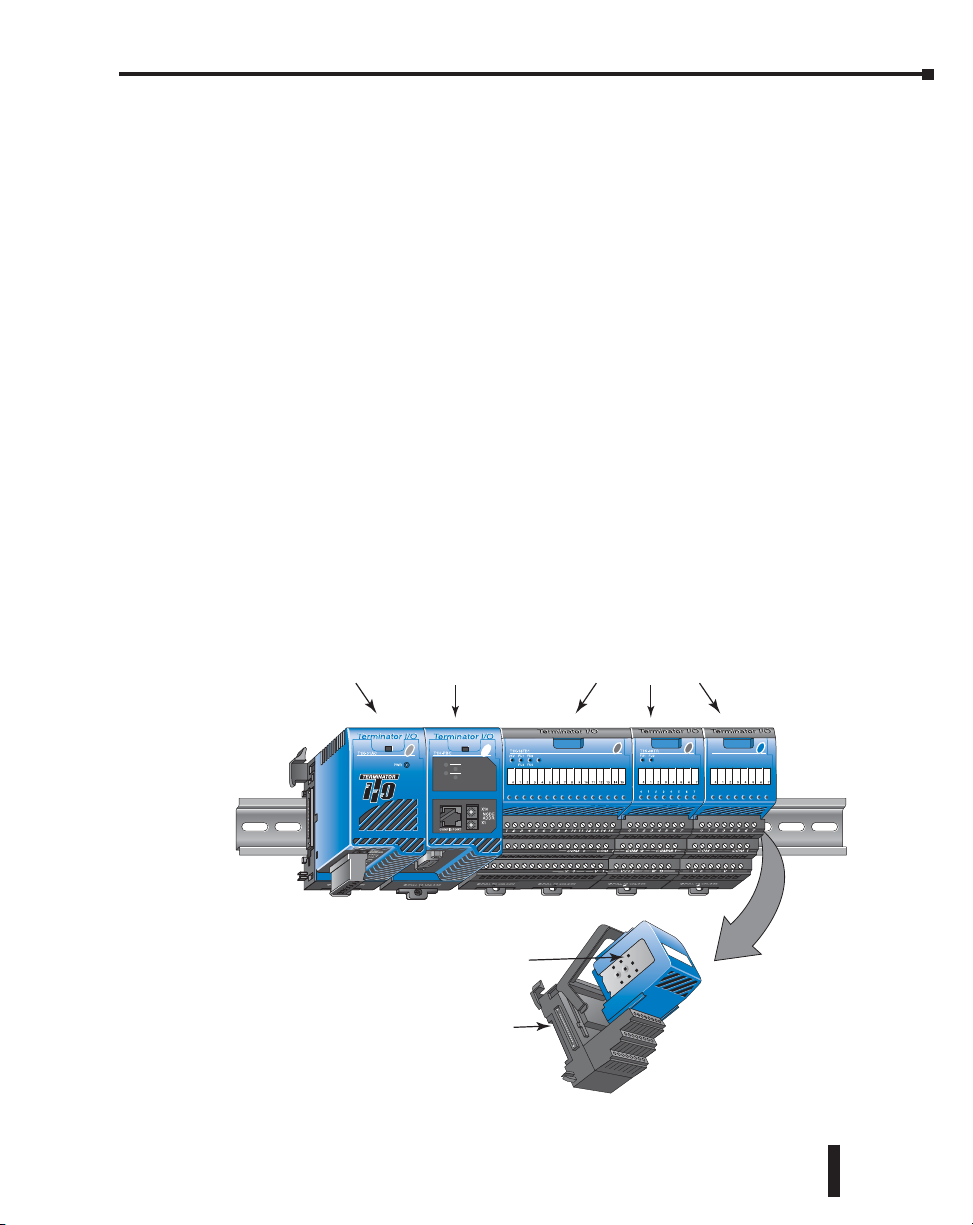
Terminator I/O System Components
PROFIBUS
Terminator I/O is a modular system which combines the functions of terminal blocks and I/O
modules for distributed I/O. Each Terminator I/O system has the following components: a
Power Supply, a Base Controller, and one or more I/O Module(s). Terminator I/O systems
can contain up to 16 I/O modules per slave (node). Each slave (node) system can be divided
into one row of base I/O plus two rows of local expansion I/O using a base expansion cable.
Power Supplies
120/240 VAC and 12/24 VDC power supplies are available. The AC version has a built-in
24VDC supply. A power supply must be the leftmost component in a slave system followed
by the base controller. Additional power supplies should be added between I/O modules to
meet power budget requirements.
I/O Modules
A Terminator I/O module assembly consists of an I/O module and a separate base,
as shown below. A complete range of discrete modules which support 12/24 VDC,
110/220 VAC and up to 7A relay outputs is offered. The analog I/O modules provide 12-bit
and 14-bit resolution and several selections of I/O signal ranges (including bipolar). The
temperature input modules provide 16 bit resolution with several temperature input range
selections. All Terminator I/O modules can be Hot Swapped (replaced) without removing
system power (except for the base controller and power supply). Refer to the I/O Module Hot
Swap section in Chapter 3 for details.
Chapter 1: Getting Started
Power Supply
Base
Controller
MODULE STATUS
LINK ACTIVE
LINK GOOD
ERROR
Profibus Base Controller
I/O Module
I/O Base
I/O Modules
Terminator Installation and I/O Manual, 3rd Edition, Rev. C
1-13
Page 19

Chapter
Chapter
Chapter
InstallatIon and
WIrIng
2
2
2
In This Chapter...
Safety Guidelines ....................................................................................................... 2-2
Mounting Guidelines ................................................................................................. 2-5
Assembling the Components .................................................................................... 2-9
Multiple Power Supplies / Local Expansion Configurations .................................. 2-11
Power Supply Wiring Guidelines ............................................................................. 2-15
Page 20
Chapter 2: Installation and Wiring
Safety Guidelines
NOTE: Products with CE marks perform their required functions safely and adhere to relevant standards
as specified by CE directives provided they are used according to their intended purpose and that the
instructions in this manual are adhered to. The protection provided by the equipment may be impaired if this
equipment is used in a manner not specified in this manual. A listing of our international affiliates is available
on our Web site: http://www.automationdirect.com
WARNING: Providing a safe operating environment for personnel and equipment is your responsibility
and should be your primary goal during system planning and installation. Automation systems can fail
and may result in situations that can cause serious injury to personnel or damage to equipment. Do not
rely on the automation system alone to provide a safe operating environment. You should use external
electromechanical devices, such as relays or limit switches, that are independent of the PLC application
to provide protection for any part of the system that may cause personal injury or damage. Every
automation application is different, so there may be special requirements for your particular application.
Make sure you follow all national, state, and local government requirements for the proper installation
and use of your equipment.
Plan for Safety
The best way to provide a safe operating environment is to make personnel and equipment
safety part of the planning process. You should examine every aspect of the system to determine
which areas are critical to operator or machine safety. If you are not familiar with PLC system
installation practices, or your company does not have established installation guidelines, you
should obtain additional information from the following sources.
• NEMA — The National Electrical Manufacturers Association, located in Washington, D.C.
publishes many different documents that discuss standards for industrial control systems. You can
order these publications directly from NEMA. Some of these include:
ICS 1, General Standards for Industrial Control and Systems
ICS 3, Industrial Systems
ICS 6, Enclosures for Industrial Control Systems
• NEC — The National Electrical Code provides regulations concerning the installation and use of
various types of electrical equipment. Copies of the NEC Handbook can often be obtained from
your local electrical equipment distributor or your local library.
• Local and State Agencies — many local governments and state governments have additional
requirements above and beyond those described in the NEC Handbook. Check with your local
Electrical Inspector or Fire Marshall office for information.
2-15
Terminator Installation and I/O Manual, 3rd Edition, Rev. C
Page 21
Three Levels of Protection
The publications mentioned provide many ideas and requirements for system safety. At a
minimum, you should follow these regulations. Also, you should use the following techniques,
which provide three levels of system control.
• Emergency stop switch for disconnecting system power
• Mechanical disconnect for output module power
• Orderly system shutdown sequence in the PLC control program
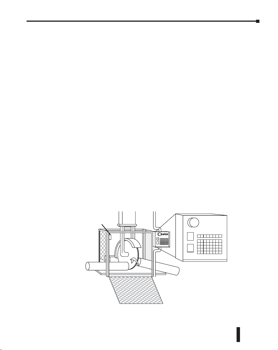
Emergency Stops
It is recommended that emergency stop circuits be incorporated into the system for every
machine controlled by a PLC. For maximum safety in a PLC system, these circuits must not
be wired into the controller, but should be hardwired external to the PLC. The emergency
stop switches should be easily accessed by the operator and are generally wired into a master
control relay (MCR) or a safety control relay (SCR) that will remove power from the PLC I/O
system in an emergency.
MCRs and SCRs provide a convenient means for removing power from the I/O system
during an emergency situation. By de-energizing an MCR (or SCR) coil, power to the input
(optional) and output devices is removed. This event occurs when any emergency stop switch
opens. However, the PLC continues to receive power and operate even though all its inputs
and outputs are disabled.
The MCR circuit could be extended by placing a PLC fault relay (closed during normal
PLC operation) in series with any other emergency stop conditions. This would cause
the MCR circuit to drop the PLC I/O power in case of a PLC failure (memory error, I/O
communications error, etc.).
Chapter 2: Installation and Wiring
Guard Line Switch
Terminator Installation and I/O Manual, 3rd Edition, Rev. C
Emergency
Stop
2-16
Page 22
Chapter 2: Installation and Wiring
Retract
Emergency Power Disconnect
A properly rated emergency power disconnect should be used to power the PLC controlled
system as a means of removing the power from the entire control system. It may be necessary
to install a capacitor across the disconnect to protect against a condition known as “outrush”.
This condition occurs when the output Triacs are turned off by powering off the disconnect,
thus causing the energy stored in the inductive loads to seek the shortest distance to ground,
which is often through the Triacs.
After an emergency shutdown or any other type of power interruption, there may be
requirements that must be met before the PLC control program can be restarted. For example,
there may be specific register values that must be established (or maintained from the state prior
to the shutdown) before operations can resume. In this case, you may want to use retentive
memory locations, or include constants in the control program to ensure a known starting
point.
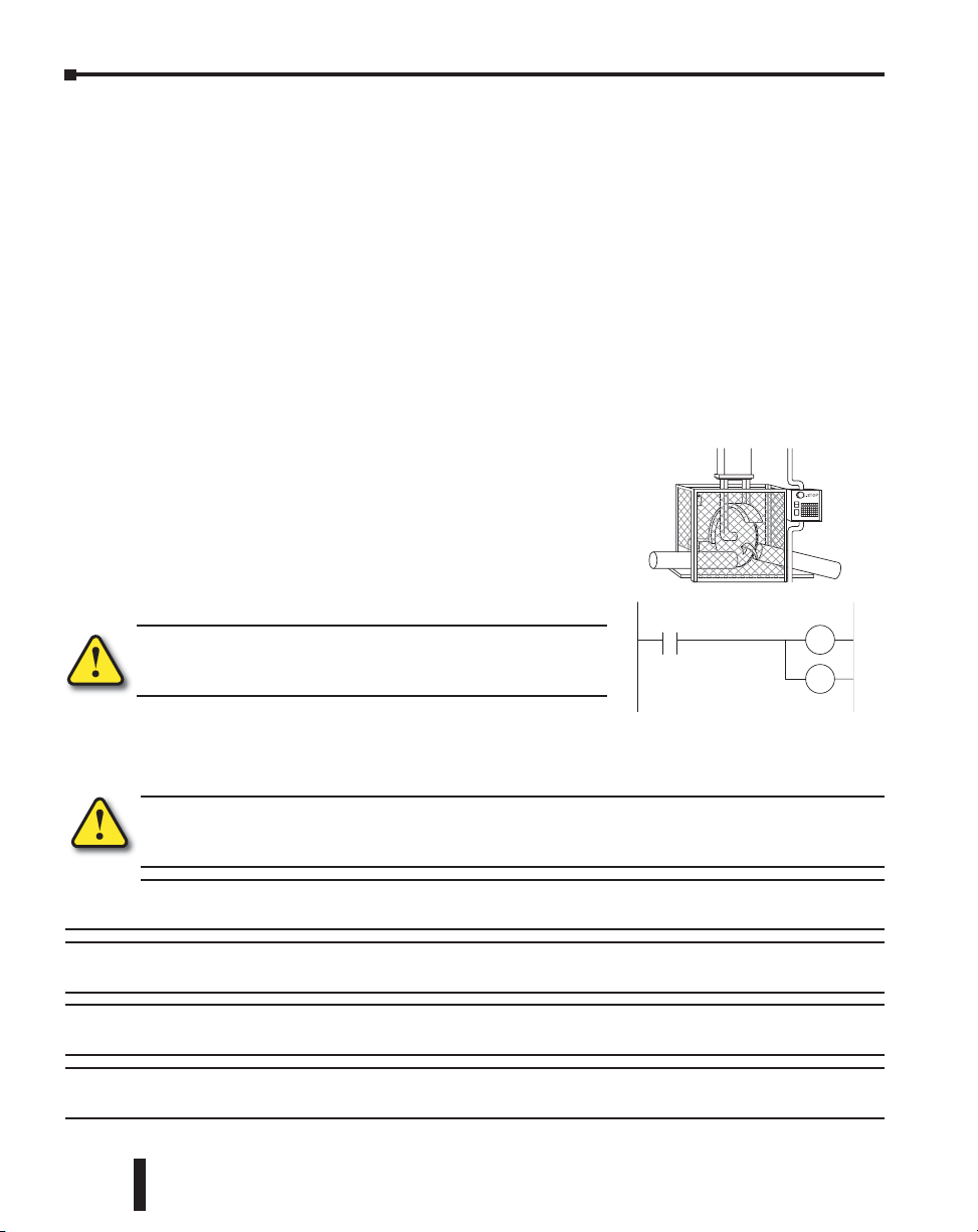
Orderly System Shutdown
Ideally, the first level of fault detection is the PLC control
program, which can identify machine problems. Certain
shutdown sequences should be performed. The types o f
problems are usually things such as jammed parts, etc. that d o
not pose a risk of personal injury or equipment damage.
WARNING: The control program must not be the only form of
protection for any problems that may result in a risk of personal
injury or equipment damage.
Jam
Detect
Turn off
Saw
RST
RST
2-17
Class 1, Division 2, Zone 2 Approval
This equipment is suitable for use in Class 1, Zone 2, Division 2, groups A, B, C and D or
non-hazardous locations only.
WARNING: Explosion Hazard! Substitution of components may impair suitability for Class 1, Division 2.
Do not disconnect equipment unless power has been switched off or area is known to be nonhazardous.
WARNING: Explosion Hazard! Do not disconnect equipment unless power has been switched off or the
area is known to be non-hazardous.
WARNING: All models used with connector accessories must use R/C (ECBT2) mating plug for all
applicable models. All mating plugs shall have suitable ratings for device.
WARNING: This equipment is designed for use in Pollution Degree 2 environments (installed within an
enclosure rated at least IP54).
WARNING: Transient suppression must be provided to prevent the rated voltage from being exceeded
by 140%.
Terminator Installation and I/O Manual, 3rd Edition, Rev. C
Page 23
Mounting Guidelines
Base Controller / Power Supply
Before installing the Terminator I/O system you will need to know the dimensions of the
components. The diagrams on the following pages provide the component dimensions to use
in defining your enclosure specifications. Remember to leave room for potential expansion.
NOTE: If you are using other components in your system, refer to the appropriate manual to determine
how those units can affect mounting dimensions.
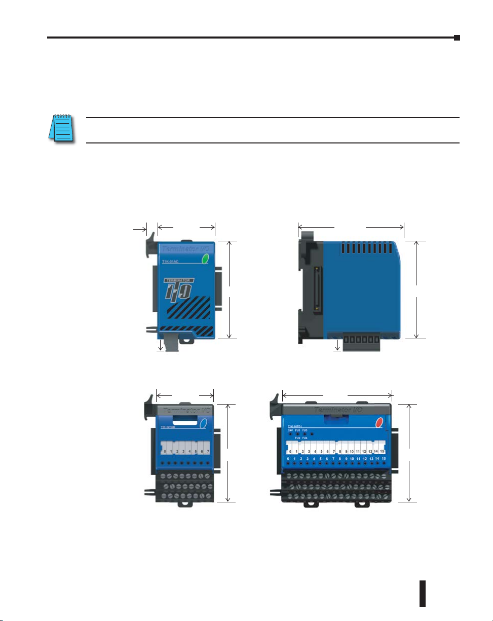
Dimensions
The following diagrams show the base controller, power supply and I/O module dimensions.
Terminator I/O components mount on 35mm wide DIN rail.
Chapter 2: Installation and Wiring
9.2 (0.36)
10.3 (0.41) 10.3 (0.41)
48 (1.89)
Terminator I/O
components
mount on 35mm
wide DIN rail.
I/O Modules
(8 pt.)
48 (1.89)
80 (3.15)
83.3 (3.28)
80 (3.15)80 (3.15)
(16 pt.)
89 (3.5)
80 (3.15)
Terminator Installation and I/O Manual, 3rd Edition, Rev. C
2-18
Page 24
Chapter 2: Installation and Wiring
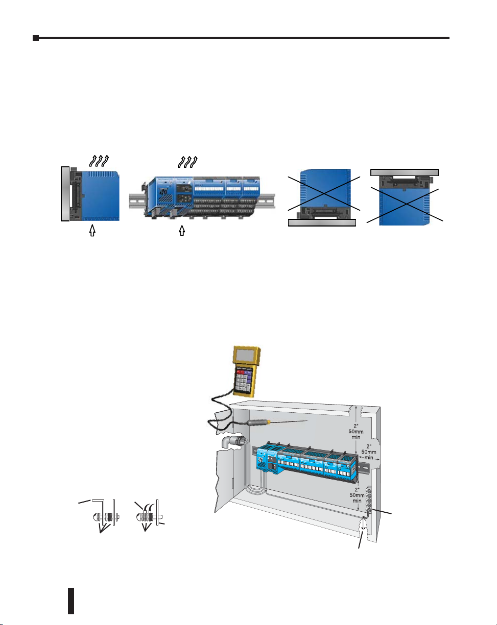
Panel Mounting and Layout
It is important to design your panel properly to help ensure that the Terminator I/O products
operate within their environmental and electrical limits. The system installation should
comply with all appropriate electrical codes and standards. It is important that the system also
conforms to the operating standards for the application to ensure proper performance.
OK
Airflow
OK
Airflow
1. Only mount the unit horizontally as shown to provide proper ventilation.
2. If you place more than one unit in a cabinet, there should be a minimum of 7.2 in. (183mm)
between them.
3. Provide a minimum clearance of 2in. (50mm) between the units and all sides of the cabinet.
There should also be at least 1.2 in. (30mm) of clearance between the base and any wiring ducts.
Temperature Probe
Power Source
2-19
Ground braid
Panel
Star Washers
copper lugs
Star Washers
Panel or single
point ground
Terminator Installation and I/O Manual, 3rd Edition, Rev. C
Earth Ground
Panel Ground
Terminal
Page 25

Chapter 2: Installation and Wiring
4. There must be a minimum of 2in. (50mm) clearance between the panel door and the nearest
Terminator I/O component.
5. The ground terminal on the Terminator I/O power supply must be connected to a single point
ground. Use copper stranded wire to achieve a low impedance. Copper eye lugs should be
crimped and soldered to the ends of the stranded wire to ensure good surface contact. Remove
anodized finishes and use copper lugs and star washers at termination points. A general rule is
to achieve a 0.1 ohm of DC resistance between the Terminator I/O slave and the single point
ground.
6. There must be a single point ground (i.e. copper bus bar) for all devices in the panel requiring
an earth ground return. The single point of ground must be connected to the panel ground
termination. The panel ground termination must be connected to earth ground. For this
connection you should use 12AWG stranded copper wire as a minimum. Minimum wire sizes,
color coding, and general safety practices should comply with appropriate electrical codes and
standards for your region. A good common ground reference (earth ground) is essential for
proper operation of the Terminator I/O. There are several methods of providing an adequate
common ground reference, including: a) Installing a ground rod as close to the panel as possible.
b) Connection to incoming power system ground.
7. Properly evaluate any installation where the ambient temperature may approach the lower or
upper limits of the specifications. Place a temperature probe in the panel, close the door and
operate the system until the ambient temperature has stabilized. If the ambient temperature
is not within the operating specification for the Terminator I/O system, measure points in the
panel in consideration for installing a cooling/heating source to provide the ambient temperature
to meet the Terminator I/O operating specifications.
8. Device mounting bolts and ground braid termination bolts should be #10 copper bolts or
equivalent. Tapped holes instead of nut-bolt arrangements should be used whenever possible.
To ensure good contact on termination areas impediments such as, paint, other coating or
corrosion should be removed in the area of contact.
9. The system is designed to be powered by 110/220 VAC or 24VDC normally available
throughout an industrial environment. Isolation transformers and noise suppression devices
are not normally necessary, but may be helpful in eliminating/reducing suspect power problems.
Enclosures
Your selection of a proper enclosure is important to ensure safe and proper operation of
your Terminator I/O system. Applications of Terminator I/O systems vary and may require
additional features. The minimum considerations for enclosures include:
• Conformance to electrical standards
• Protection from the elements in an industrial environment
• Common ground reference
• Maintenance of specified ambient temperature
• Access to equipment
• Security or restricted access
• Sufficient space for proper installation and maintenance of equipment
Terminator Installation and I/O Manual, 3rd Edition, Rev. C
2-20
Page 26
Chapter 2: Installation and Wiring
Environmental Specifications
The following table lists the environmental specifications that apply to the Terminator I/O
modules. Be sure to check the specifications of the controller you are using. Also refer to the
appropriate I/O module specifications in Chapter 3 for the temperature derating curves for the
specific module.
Specification Rating
Storage temperature -4°F to 158°F (-20°C to 70°C)
Ambient operating temperature 32°F to 131°F (0°C to 55°C)
Ambient humidity* 5%–95% relative humidity (non-condensing
Vibration resistance MIL STD 810C, Method 514.2
Shock resistance MIL STD 810C, Method 516.2
Noise Immunity
Atmosphere
*Equipment will operate at low humidity. However, static electricity problems occur much more
frequently at lower humidity levels. Make sure you take adequate precautions when you touch the
equipment. Consider using ground straps, anti-static floor coverings, etc., if you use the equipment
in low humidity environments.
Power
The power source must be capable of supplying voltage and current complying with the base
power supply specifications.
NEMA (ICS3-304)
Impulse noise 1µs, 1000V
FCC class A
RFI (144MHz, 430MHz 10W, 10cm
No corrosive gases. The level for the environmental
pollution = 2. (UL840)
2-21
Specification AC Power Supply DC Power Supply
Part Number T1K-01AC T1K-01DC
Input Voltage Range
Maximum Inrush Current 20A 10A
Maximum Power 50VA 20W
Voltage Withstand (dielectric) 1 minute @ 1500VAC between primary, secondary, field ground
Insulation Resistance > 10Mq at 500VDC
Auxiliary 24VDC Output
110/220 VAC (85–264 VAC)
50/60 Hz (47–63 Hz)
20–28 VDC, 10% ripple max. 300mA.
Max. 500mA @ 24VDC can be
achieved if the 5VDC power budget
rating of 2000mA is reduced to
1500mA. See power budget section.
12/24 VDC (10.8–26.4 VDC) with
less than 10% ripple
None
Agency Approvals
Some applications require agency approvals. Typical agency approvals which your application
may require are:
• UL (Underwriters’ Laboratories, Inc.)
• CSA (Canadian Standards Association)
• FM (Factory Mutual Research Corporation)
• CUL (Canadian Underwriters’ Laboratories, Inc.)
Terminator Installation and I/O Manual, 3rd Edition, Rev. C
Page 27
Assembling the Components
Chapter 2: Installation and Wiring
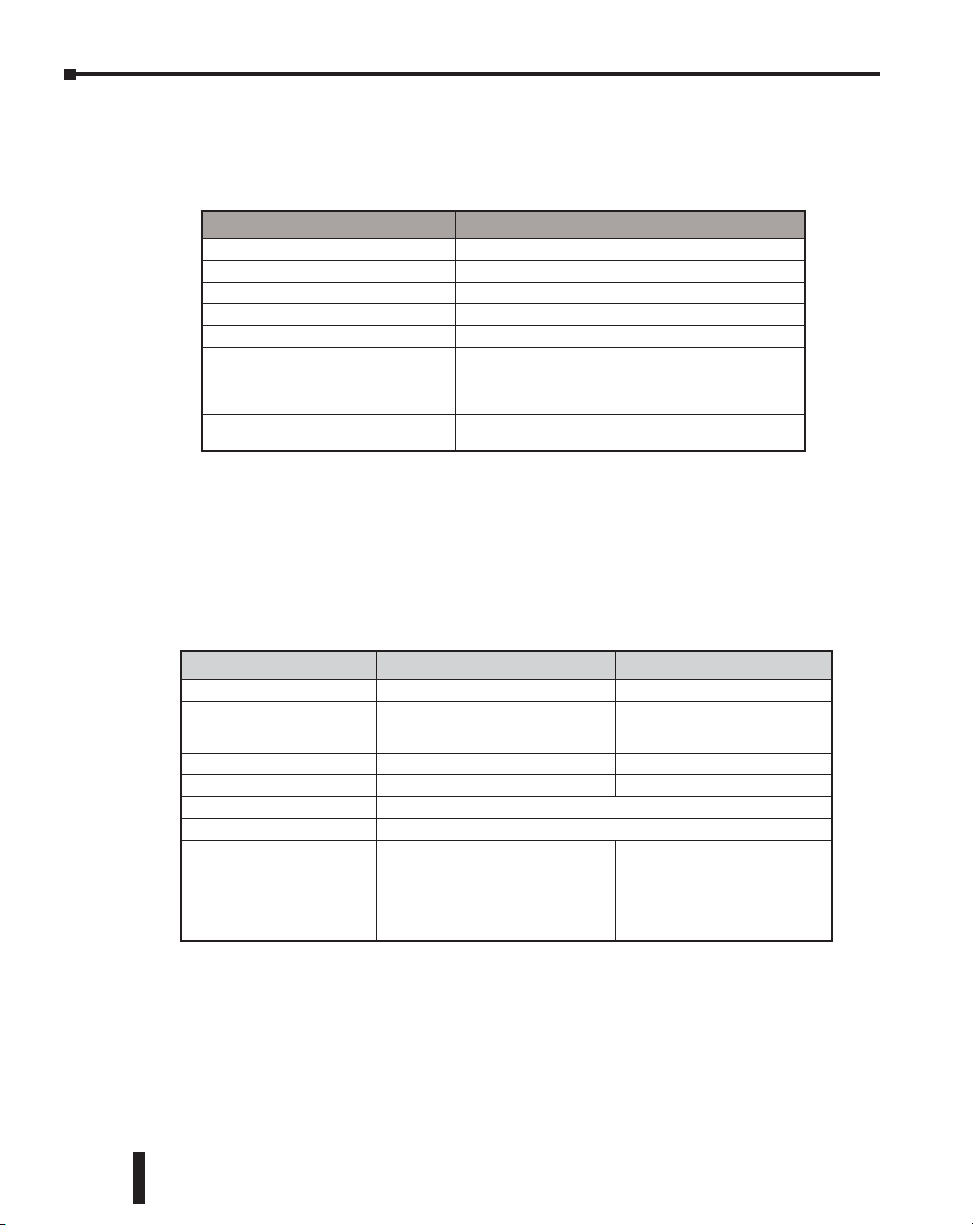
Assembling the I/O Modules and Bases
INSERT MODULE INTO BASE
1. Pull base arm back to allow space
for module to enter base.
2. Align module slides with base track.
3. Press module firmly into base.
1
3
2
Mounting the Components on DIN Rail
2
3
NOTE: Do not force the base controller on the DIN rail. Due to slight size variations in different
manufacturers’ DIN rail, it may be necessary to first unlatch the locking tab, rotate the module into place,
then latch the locking tab.
INSTALL ON DIN RAIL
1. Make sure the locking tab is in the latched position (pushed in).
2. Hook upper tab over upper flange of DIN rail.
3. Tilt the unit toward DIN rail until it snaps securely to DIN rail.
1
Terminator Installation and I/O Manual, 3rd Edition, Rev. C
2-22
Page 28
Chapter 2: Installation and Wiring
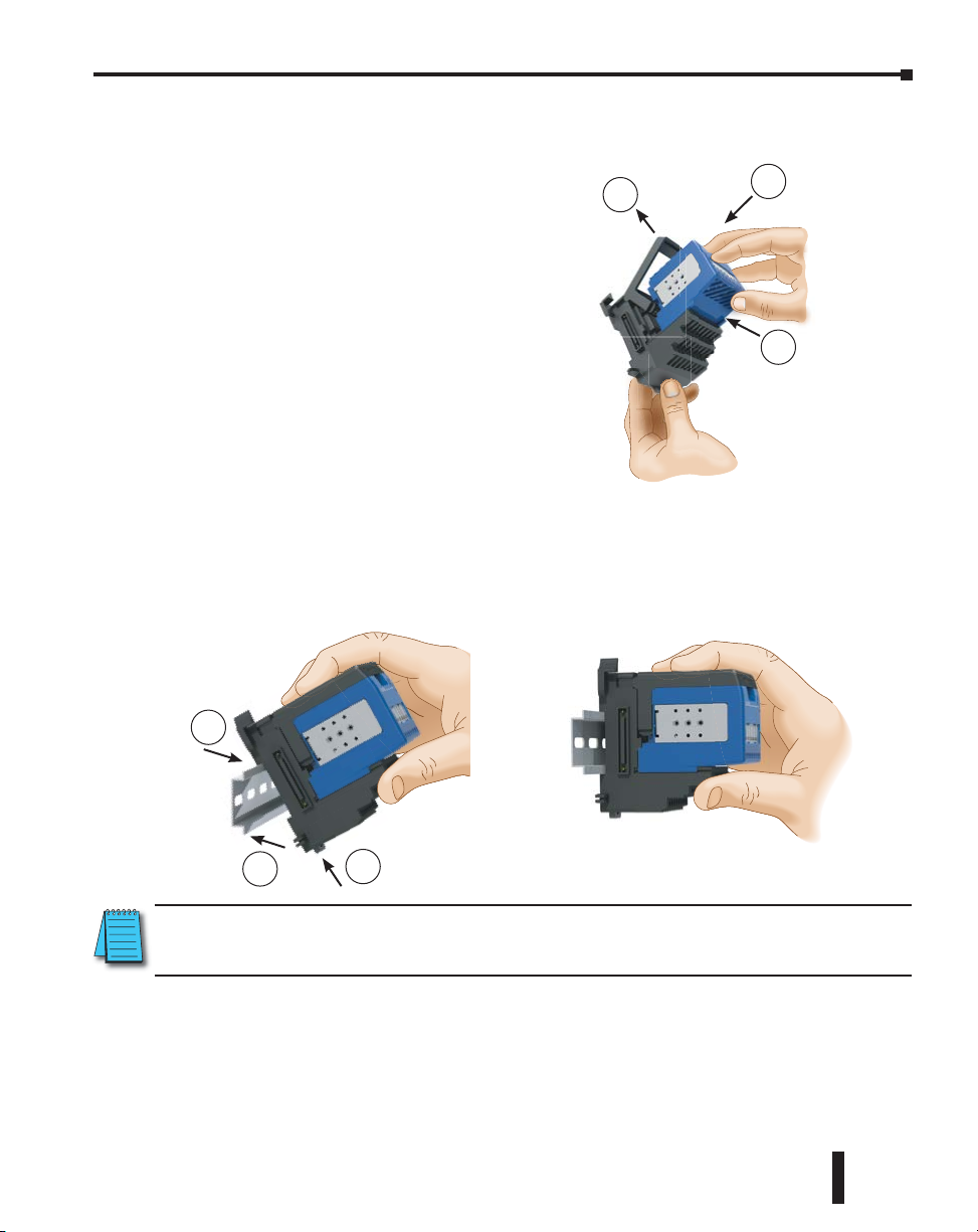
Connecting the Components on the DIN Rail
SLIDE ASSEMBLY INTO POSITION ON THE DIN RAIL
Slide the module assembly on the DIN rail until the clip arm attaches securely to the
adjacent module.
NOTE: One power supply is required in the leftmost component position followed by the base controller.
Additional power supplies should be added between I/O modules as necessary to meet power budget
requirements (see ch 3, page 3-18). Each power supply powers the modules to its right, but is interrupted
by the next power supply.
2-23
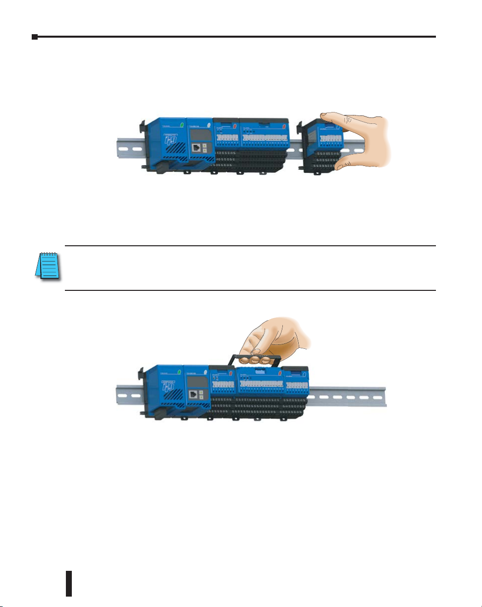
Removing I/O Modules from the Base
To remove a module from the base, grip the center of the base arm and rotate outward releasing
the module. Lift the module from the base.
To remove a module assembly from the DIN rail, lift the clip arm up and slide the module
assembly away from the adjacent module. Pull the locking tab down (out) and lift the assembly
off the DIN rail. Refer to the “I/O Module Hot Swap Feature” section in Chapter 3 to remove
an I/O module with Terminator I/O system power ON.
Terminator Installation and I/O Manual, 3rd Edition, Rev. C
Page 29
Chapter 2: Installation and Wiring
Multiple Power Supplies / Local Expansion Configurations
Multiple Power Supply Configuration
It is possible to have multiple power supplies in a single slave (node) system to meet power
budget requirements. One power supply is required in the leftmost component position
followed by the base controller. Additional power supplies should be added between I/O
modules as necessary to meet power budget requirements. There are some restrictions on where
power supplies can be placed in the system when using the T1K-05CBL-RR(-1) expansion base
cable. Each power supply powers the modules to its right, but is interrupted by the next power
supply. Each slave (node) system can be divided into one row of base I/O plus two rows of
local expansion I/O up to a total of 16 I/O modules.
Expansion cables are available in two configurations: one that allows 24VDC base power to
pass and one that does not (both cables pass the 5VDC base power). The “-1” version of the
expansion cables, pass 24VDC on an isolated wire. Any local expansion DC input modules
configured for “internal power” (current sourcing) must either have a power supply preceding
it on the same base or have a “-1” version cable pass 24VDC from a power supply on the
preceding base.
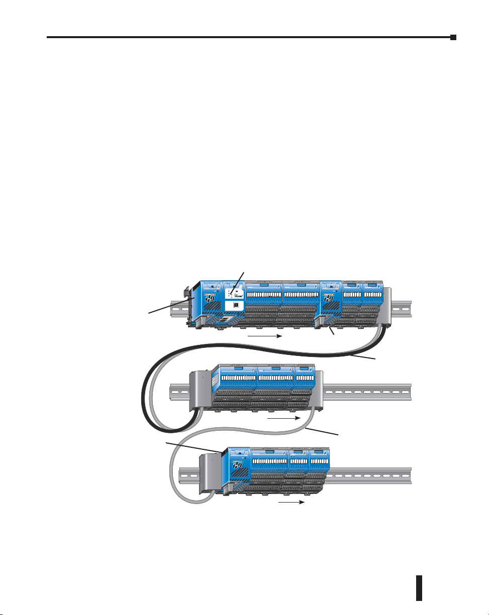
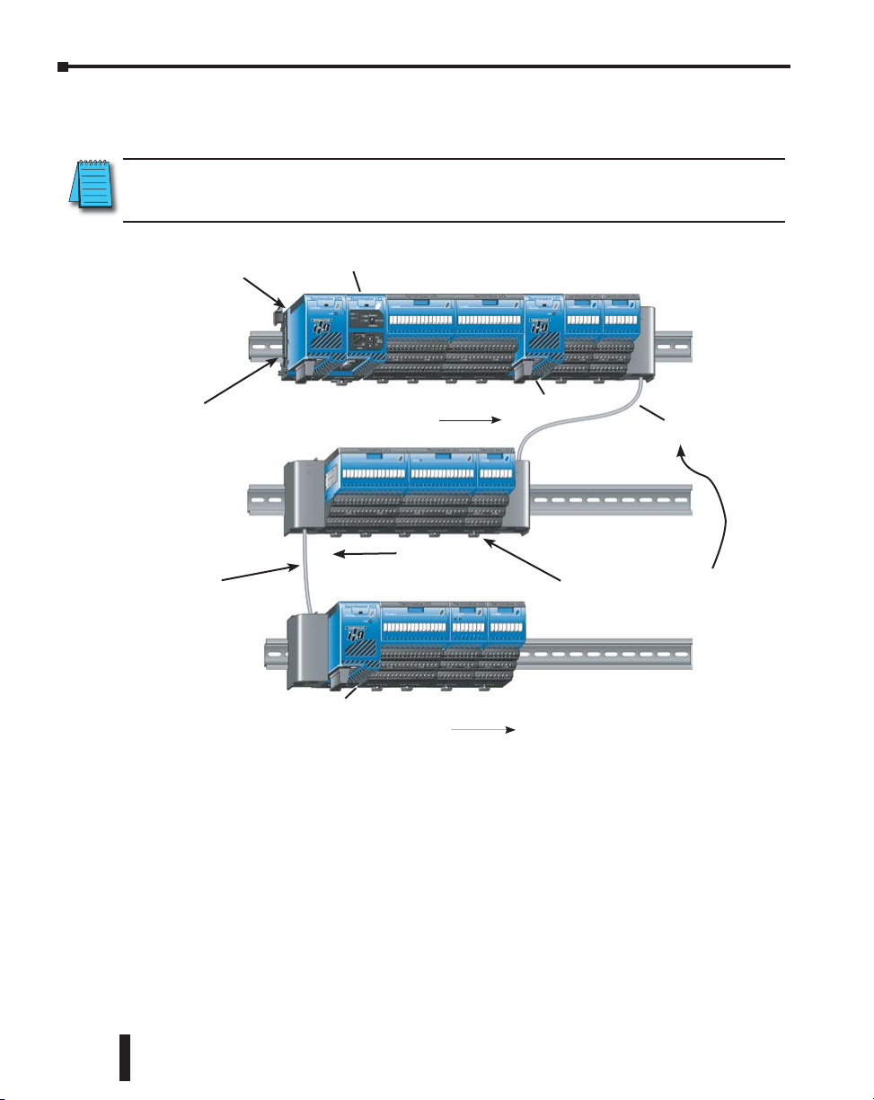
Example Using T1K-10CBL and T1K-10CBL-1 Expansion Cables
CPU
T1H-DM1E
TERM
RUN
RUNSTOP
USB
I/O
TX
STAT
RX
USB
PGM
Power Supply #1
(The power supply must be
the left most component in
a system followed by the
base controller.)
I/O Addressing
PORT
Local Base I/O
Power Supply #2
T1K-10CBL-1
I/O Addressing
1st Local Expansion I/O
T1K-10CBL
Power Supply #3
2nd Local Expansion I/O
I/O Addressing
System shown above: The first power supply powers the base controller and the two I/O
modules to its right. The second power supply powers the two modules to its right and the
three I/O modules on the first local expansion base. Power Supply #3 powers the three I/O
modules to its right on the second local expansion base. This serves as an example only, your
power budget requirements will vary depending on the I/O modules used.
Terminator Installation and I/O Manual, 3rd Edition, Rev. C
2-24
Page 30
Chapter 2: Installation and Wiring
Example Using T1K-05CBL-RR-1 and T1K-05CBL-LL Expansion Cables
NOTE: The T1K-05CBL-RR-1 expansion cable with an isolated 24VDC lead was discontinued in 2015 and is
no longer available. The following examples show this cable. As an alternative, consider using the
T1K-10CBL(-1) cables as shown in the example on the preceding page.
Power Supply #1
(The power supply must be
the left most component in
a system followed by the
base controller.)
Do not connect a
T1K-05CBL-LL to the
left side of the local
I/O base.
T1K-05CBL-LL
System shown above: The first power supply powers the base controller and the two I/O
modules to its right. The second power supply powers the two modules to its right and the
three I/O modules on the first local expansion base. When a T1K-05CBL-RR-1 is used, the
expansion I/O assignments are from right to left (reversed). A power supply cannot be used
on a base that is connected to a system by a T1K-05CBL-RR-1. Power Supply #3 powers the
three I/O modules to its right on the second local expansion base. This serves as an example
only, your power budget requirements will vary depending on the I/O modules used.
Base Controller
I/O Addressing
Power Supply #3
I/O Addressing
I/O Addressing
Local Base I/O
Power Supply #2
T1K-05CBL-RR-1
1st Local Expansion I/O
A power supply cannot
be used on a base that is
connected to a system by
a T1K-05CBL-RR-1.
2nd Local Expansion I/O
2-25
Terminator Installation and I/O Manual, 3rd Edition, Rev. C
Page 31

Chapter 2: Installation and Wiring
Example Using T1K-10CBL and T1K-05CBL-RR-1 Expansion Cables
Base Controller
Power Supply #1
(The power supply must be
the left most component in
a system followed by the
base controller.)
I/O Addressing
Power Supply #3
I/O Addressing
Power Supply #2
T1K-10CBL
1st Local Expansion I/O
T1K-05CBL-RR-1
A power supply cannot
be used on a base that is
connected to a system by
a T1K-05CBL-RR-1.
Local Base I/O
2nd Local Expansion I/O
I/O Addressing
System shown above: The first power supply powers the base controller and the two I/O
modules to its right. The second power supply powers the two modules to its right. Power
Supply #3 powers the three I/O modules to its right on the first local expansion base and the
three I/O modules on the second local expansion base. When a T1K-05CBL-RR-1 is used, the
expansion I/O assignments are from right to left (reversed). A power supply cannot be used on
a base that is connected to a system by a T1K-05CBL-RR-1. This serves as an example only,
your power budget requirements will vary depending on the I/O modules used.
Terminator Installation and I/O Manual, 3rd Edition, Rev. C
2-26
Page 32

Chapter 2: Installation and Wiring
Example Using T1K-05CBL-RR-1 Expansion Cables
Base Controller
Power Supply #1
(The power supply must be
the left most component in
a system followed by the
base controller.)
System shown above: The first power supply powers the base controller and the two I/O
modules to its right. The second power supply powers the two modules to its right and the
five I/O modules on the first local expansion base. When a T1K-05CBL-RR-1 is used, the
expansion I/O assignments are from right to left (reversed). A power supply cannot be used on
a base that is connected to a system by a T1K-05CBL-RR-1. This serves as an example only,
your power budget requirements will vary depending on the I/O modules used.
I/O Addressing
Power Supply #2
I/O Addressing
Local Base I/O
T1K-05CBL-RR-1
A power supply cannot
be used on a base that is
connected to a system by
a T1K-05CBL-RR-1.
1st Local Expansion I/O
2-27
Terminator Installation and I/O Manual, 3rd Edition, Rev. C
Page 33

Power Supply Wiring Guidelines
Power Wiring
The diagram below shows the terminal connections located on the Terminator I/O AC
and DC power supplies. The table below shows the wire size and the recommended power
supply terminal screw torque.
Chapter 2: Installation and Wiring
110/220 VAC Terminal Strip
Power Supply T1K-01AC T1K-01DC
Wire Size
Recommended Torque
Solid: 24–12 AWG
Stranded: 24–12 AWG
4.43–5.31 lb·in
(0.5–0.6 N·m)
12/24 VDC Terminal Strip
Solid: 24–12 AWG
Stranded: 24–12 AWG
4.43–5.31 lb·in
(0.5–0.6 N·m)
Terminator Installation and I/O Manual, 3rd Edition, Rev. C
2-28
Page 34

Chapter
Chapter
Chapter
I/O WIrIng and
SpecIfIcatIOnS
3
3
2
In This Chapter...
I/O Wiring Strategies ................................................................................................ 3-3
I/O Modules Position, Wiring and Specifications ................................................... 3-15
I/O Module Hot Swap Feature ................................................................................ 3-22
Calculating the Power Budget ................................................................................ 3-23
I/O Specification Terms ........................................................................................... 3-27
T1K-01AC, T1K-01DC Power Supply ....................................................................... 3-29
T1H-EBC Ethernet Base Controller (Obsolete) ....................................................... 3-31
T1H-EBC100 Ethernet Base Controller .................................................................... 3-33
T1K-DEVNETS .......................................................................................................... 3-35
T1K-MODBUS Base Controller ................................................................................ 3-37
T1K-RSSS Remote I/O Base Controller ................................................................... 3-39
T1H-PBC Profibus Base Controller .......................................................................... 3-41
T1K-08ND3 DC Input ............................................................................................... 3-43
T1K-16ND3 DC Input ............................................................................................... 3-45
T1K-08NA-1 AC Input .............................................................................................. 3-47
T1K-16NA-1 AC Input .............................................................................................. 3-49
T1K-08TD1 DC Output ............................................................................................ 3-51
T1K-08TD2-1 DC Output ......................................................................................... 3-53
T1H-08TDS Isolated DC Output .............................................................................. 3-55
T1K-16TD1 DC Output ............................................................................................ 3-57
T1K-16TD2-1 DC Output ......................................................................................... 3-59
T1K-08TA AC Output ............................................................................................... 3-61
Page 35

Table of Contents
T1K-16TA AC Output ............................................................................................... 3-63
T1K-08TAS AC Output ............................................................................................. 3-65
T1K-08TR Relay Output ........................................................................................... 3-67
T1K-16TR Relay Output ........................................................................................... 3-69
T1K-08TRS Relay Output ......................................................................................... 3-71
T1F-08AD-1 8-Channel Current Analog Input ........................................................ 3-73
T1F-08AD-2 8-Channel Voltage Analog Input ........................................................ 3-75
T1F-16AD-1 16-Channel Current Analog Input ...................................................... 3-77
T1F-16AD-2 16-Channel Voltage Analog Input ...................................................... 3-79
T1F-08DA-1 8-Channel Current Analog Output ..................................................... 3-81
T1F-08DA-2 8-Channel Analog Output ................................................................... 3-83
T1F-16DA-1 16-Channel Current Analog Output ................................................... 3-85
T1F-16DA-2 16-Channel Voltage Analog Output ................................................... 3-87
T1F-16RTD RTD Input Module ................................................................................ 3-89
T1F-16TMST Thermistor Input Module .................................................................. 3-93
T1F-14THM 14-Channel Thermocouple Input ........................................................ 3-97
Setting Module Jumpers .......................................................................................... 3-99
T1F-8AD4DA-1 8-Channel Current Analog Input
4 Channel Current Analog Output .............................................. 3-101
T1F-8AD4DA-1 ....................................................................................................... 3-103
T1F-8AD4DA-2 8-Channel Voltage Analog Input
4 Channel Voltage Analog Output ............................................. 3-105
T1F-8AD4DA-2 ....................................................................................................... 3-107
T1H-CTRIO Counter I/O Module ........................................................................... 3-109
T1K-08B(-1) I/O Module Base ............................................................................... 3-115
T1K-16B(-1) I/O Module Base ............................................................................... 3-115
T1K-10CBL, T1K-10CBL-1 Expansion Cable .......................................................... 3-117
T1K-5CBL-LL(-1) Expansion Cable ......................................................................... 3-119
T1K-5CBL-RR(-1) Expansion Cable ........................................................................ 3-119
Cable Connection Examples .................................................................................. 3-121
Terminator Installation and I/O Manual, 3rd Edition, Rev. C
3-2
Page 36

I/O Wiring Strategies
Primary Side Secondary, or
Field Side
Operator Interface, or Network
Boundary
Boundary
Output Circuit
Terminator I/O System Isolation Boundaries
The Terminator I/O system is very flexible and will work in many different wiring
configurations. By studying this section before actual installation, you can probably find the
best wiring strategy for your application. This will help to lower system cost, wiring errors, and
avoid safety problems.
Terminator I/O system circuitry is divided into three main regions separated by isolation
boundaries, shown in the drawing below. Electrical isolation provides safety, so that a fault
in one area does not damage another. A transformer in the power supply provides magnetic
isolation between the primary and secondary sides. Opto-couplers provide optical isolation
in Input and Output circuits. This isolates logic circuitry from the field side, where factory
machinery connects. Note the discrete inputs are isolated from the discrete outputs, because
each is isolated from the logic side. Isolation boundaries protect the operator interface (and
the operator) from power input faults or field wiring faults. When wiring a Terminator I/O
system, it is extremely important to avoid making external connections that connect logic side
circuits to any other.
Terminator I/O System
Power Input
Main
Power
Supply
Logic side
Slave
CPU
Chapter 3: I/O Wiring and Specifications
(backplane)
(backplane)
Input
Module
Output
Module
Inputs
Outputs
Isolation
The next figure shows the physical layout of a Terminator I/O system, as viewed from the
front. In addition to the basic circuits covered above, AC-powered bases include an auxiliary
+24VDC power supply with its own isolation boundary. Since the supply output is isolated
from the other three circuits, it can power input and/or output circuits!
Primary Side Secondary, or
Power Input
+24 VDC Out
Main
Power
Supply
Auxiliary
+24 VDC
Supply
Terminator Installation and I/O Manual, 3rd Edition, Rev. C
Programming Device,
Terminator I/O
System
Slave
Internal
CPU
Comm.
Operator
Interface
Logic side
Input Module
Inputs CommonsCommonsOutputs
Field Side
Isolation
Backplane
Output Module
Supply for
3-3
Page 37

Chapter 3: I/O Wiring and Specifications
In some cases, using the built-in auxiliary +24VDC supply can result in a cost savings for
your control system. It can power combined loads up to 500mA if power budget allows. Be
careful not to exceed the current rating of the supply. If you are the system designer for your
application, you may be able to select and design in field devices which can use the +24VDC
auxiliary supply.
Powering I/O Circuits with the Auxiliary Supply
All AC power supplies feature an internal auxiliary supply. If input devices AND output loads
need +24VDC power, the auxiliary supply may be able to power both circuits as shown in the
following diagram.
AC Power
Power Input
Auxiliary
+24 VDC
Supply
+
Terminator I/O System
Input Module
Inputs Com. Outputs Com.
–
Output Module
Loads
DC-powered units are designed for application environments in which low-voltage DC
power is more readily available than AC. These include a wide range of battery-powered
applications, such as remotely-located control, in vehicles, portable machines, etc. For this
type of application, all input devices and output loads typically use the same DC power source.
Typical wiring for DC-powered applications is shown in the following diagram.
+
–
+
–
Power Input
DC Power
Terminator I/O System
Input Module
Inputs Com. Outputs Com.
Output Module
3-4
Loads
Terminator Installation and I/O Manual, 3rd Edition, Rev. C
Page 38

Chapter 3: I/O Wiring and Specifications
Powering I/O Circuits Using Separate Supplies
In most applications it will be necessary to power the input devices from one power source, and
to power output loads from another source. Loads often require high-energy AC power, while
input sensors use low-energy DC. If a machine operator is likely to come in close contact with
input wiring, then safety reasons also require isolation from high-energy output circuits. It is
most convenient if the loads can use the same power source as the Terminator I/O system, and
the input sensors can use the auxiliary supply, as shown to the left in the figure below.
If the loads cannot be powered from the system supply, then a separate supply must be used as
shown to the right in the figure below.
Power Input
Auxiliary
+24 VDC
Supply
–
+
AC Power
Terminator I/O System
Input Module
Inputs Com. Outputs Com.
Output Module
Loads
Power Input
+
Auxiliary
+24 VDC
Supply
–
AC Power
Terminator I/O System
Input Module
Inputs Com. Outputs Com.
Output Module
Loads
Load
Supply
Some applications will use the external power source to also power the input circuit. This
typically occurs on DC-powered systems, as shown in the drawing below to the left. The
inputs share the system power source supply, while the outputs have their own separate supply.
A worse-case scenario, from a cost and complexity view-point, is an application which requires
separate power sources for the Terminator I/O system, input devices, and output loads. The
example wiring diagram below on the right shows how this can work, but also the auxiliary
supply output is an unused resource. You will want to avoid this situation if possible.
+
+
–
Power Input
DC Power
–
Terminator I/O System
Input Module
Inputs Com. Outputs Com.
Power Input
Output Module
Auxiliary
+24 VDC
Supply
AC Power
Terminator I/O System
Input Module
Inputs Com. Outputs Com.
Output Module
–
+
Loads
Load
Supply
Input
Supply
Loads
Terminator Installation and I/O Manual, 3rd Edition, Rev. C
Load
Supply
3-5
Page 39

Chapter 3: I/O Wiring and Specifications
Sinking / Sourcing Concepts
Before going further in the study of wiring strategies, you must have a solid understanding of
“sinking” and “sourcing” concepts. Use of these terms occurs frequently in input or output
circuit discussions. It is the goal of this section to make these concepts easy to understand,
further ensuring your success in installation. First the following short definitions are provided,
followed by practical applications.
Sinking = provides a path to supply ground (-)
Sourcing = provides a path to supply source (+)
First you will notice these are only associated with DC circuits and not AC, because of the
reference to (+) and (-) polarities. Therefore, sinking and sourcing terminology only applies
to DC input and output circuits. Input and output points that are sinking or sourcing only
can conduct current in only one direction. This means it is possible to connect the external
supply and field device to the I/O point with current trying to flow in the wrong direction, and
the circuit will not operate. However, you can successfully connect the supply and field device
every time by understanding “sourcing” and “sinking”.
For example, the figure to the right depicts
a “sinking” input. To properly connect the
external supply, you will have to connect it so
the input provides a path to ground (-). Start
at the Terminator I/O system input terminal,
follow through the input sensing circuit, exit at
the common terminal, and connect the supply (-)
to the common terminal. By adding the switch,
between the supply (+) and the input, the circuit
has been completed. Current flows in the direction
of the arrow when the switch is closed.
Terminator I/O System
Input
(sinking)
+
–
Common
Input
Sensing
3-6
By applying the circuit principle above to the four possible combinations of input/output
sinking/sourcing types as shown below. The I/O module specifications at the end of this
chapter list the input or output type.
Sinking Input Sinking Output
+
–
Sourcing Input Sourcing Output
+
–
Terminator I/O System
Input
Common
Terminator I/O System
Common
Input
Input
Sensing
Input
Sensing
Terminator I/O System
Output
Switch
Terminator I/O System
Output
Switch
Output
Common
Common
Output
Load
+
–
+
–
Load
Terminator Installation and I/O Manual, 3rd Edition, Rev. C
Page 40

Chapter 3: I/O Wiring and Specifications
AC supply AC or DC supply
DC supply
I/O “Common” Terminal Concepts
In order for an I/O circuit to operate, current
must enter at one terminal and exit at another.
Therefore, at least two terminals are associated
with every I/O point. In the figure to the right,
the Input or Output terminal is the main path
for the current. One additional terminal must
Field
Device
+
–
provide the return path to the power supply..
If there was unlimited space and budget for
I/O terminals, every I/O point could have two
dedicated terminals as the figure above shows.
However, providing this level of flexibility is not
practical or even necessary for most applications.
So, most Input or Output points are in groups
which share the return path (called commons).
The figure to the right shows a group (or bank)
of 4 input points which share a common return
path. In this way, the four inputs require only five
terminals instead of eight.
NOTE: In the circuit above, the current in the common path is 4 times any channel’s input current when
all inputs are energized. This is especially important in output circuits, where heavier gauge wire is
sometimes necessary on commons.
+
–
Terminator I/O System
Main Path
(I/O Point)
Return Path
Terminator I/O System
Input 1
Input 2
Input 3
Input 4
Common
Input
Sensing
I/O
Circuit
Most Terminator I/O input and output modules
group their I/O points into banks that share a
common return path. The best indication of I/O
common grouping is on the wiring label, such as the
one shown to the right. The miniature schematic
shows two banks of circuits with four output points
in each. The common terminal for each is labeled
COM 0 and COM 1, respectively.
In this wiring label example, the positive terminal
of a DC supply connects to the common terminals.
Some symbols you will see on the wiring labels, and
their meanings are:
Input Switch Output Load
Terminator Installation and I/O Manual, 3rd Edition, Rev. C
+–
L
3-7
Page 41

Chapter 3: I/O Wiring and Specifications
Connecting DC I/O to Solid State Field Devices
In the previous section on Sourcing and Sinking concepts, the DC I/O circuits were explained
to only allow current to flow one way. This is also true for many of the field devices which have
solid-state (transistor) interfaces. In other words, field devices can also be sourcing or sinking.
When connecting two devices in a series DC circuit, one must be wired as sourcing and the other as
sinking:
Solid State Input Sensors
Terminator I/O DC input modules are flexible because they detect current flow in either
direction, so they can be wired as either sourcing or sinking. In the following circuit, a field
device has an open-collector NPN transistor output. It sinks current from the input point,
which sources current. The power supply can be the +24V auxiliary supply or another supply
(+12VDC or +24VDC), as long as the input specifications are met.
Field Device
Output
(sinking)
Ground
In the next circuit, a field device has an open-emitter PNP transistor output. It sources current
to the input point, which sinks the current back to ground. Since the field device is sourcing
current, no additional power supply is required.
Supply
Terminator I/O System DC Input
Input
(sourcing)
+–
Common
3-8
Field Device
+V
Output (sourcing)
Ground
Terminator I/O System DC Input
Input
(sinking)
Common
Solid State Output Loads
Sometimes an application requires connecting an output point to a solid state input on a
device. This type of connection is usually made to carry a low-level control signal, not to send
DC power to an actuator.
Several of the Terminator I/O DC output modules are the sinking type. This means that each
DC output provides a path to ground when it is energized. In the following circuit, the output
point sinks current to the output common when energized. It is connected to a sourcing input
of a field device input.
Terminator I/O System DC Sinking Output
+DC pwr
Power
Output
(sinking)
Common
+
–
10–30 VDC
(sourcing)
Ground
Terminator Installation and I/O Manual, 3rd Edition, Rev. C
Field Device
+V
Input
Page 42

Chapter 3: I/O Wiring and Specifications
V
pullup
Terminator I/O DC Sourcing Output
In the next example a sinking DC output point is connected to the sinking input of a field
device. This is a little tricky, because both the Terminator I/O system output and field device
input are sinking type. Since the circuit must have one sourcing and one sinking device, a
sourcing capability needs to be added to the Terminator I/O system output by using a pull-up
resistor. In the circuit below, resistor R
circuit power input.
Terminator I/O System DC Output
+DC pwr
(sinking)
NOTE 1: DO NOT attempt to drive a heavy load (>25mA) with this pull-up method.
NOTE 2: Using the pull-up resistor to implement a sourcing output has the effect of inverting the output
point logic. In other words, the field device input is energized when the Terminator I/O system output
is OFF, from a ladder logic point-of-view. Your ladder program must comprehend this and generate an
inverted output. Or, you may choose to cancel the effect of the inversion elsewhere, such as in the field
device.
Example: Circuit with no Suppression
Power
R
pull-up
(sourcing)
Output
Common
is connected from the output to the DC output
pull-up
Field Device
R
input
Supply
+
–
Input
(sinking)
Ground
It is important to choose the correct value of R
nominal input current to the field device (I input) when the input is energized. If this value is
not known, it can be calculated as shown (a typical value is 15mA). Then use I input and the
voltage of the external supply to compute R
in order to size R
I
input
R
pull-up
Of course, the easiest way to drive a sinking input field device as shown below is to use a
DC sourcing output module. The Darlington NPN stage will have about 1.5 V ON-state
saturation, but this is not a problem with low-current solid-state loads.
. In order to do so, you need to know the
pull-up
. Then calculate the power P
R
–
(sourcing)
pull-up
input
Supply
P
pull-up
Input
+
–
(sinking)
Ground
=
Field Device
R
input
=
=
pull-up
V
+DC pwr
properly.
input (turn–on)
R
input
supply
– 0.7
I
input
Common
Output
Terminator Installation and I/O Manual, 3rd Edition, Rev. C
pull-up
V
supply
R
(in watts),
2
3-9
Page 43

Chapter 3: I/O Wiring and Specifications
Relay Output Guidelines
Several output modules in the Terminator I/O family feature relay outputs: T1K-08TR,
T1K-16TR, and T1K-08TRS. Relays are best for the following applications:
• Loads that require higher currents than the solid-state outputs can deliver
• Cost-sensitive applications
• Some output channels need isolation from other outputs (such as when some loads
require different voltages than other loads)
Some applications in which NOT to use relays:
• Loads that require currents under 10mA
• Loads which must be switched at high speed or heavy duty cycle
Relay output module contacts are available in Form
A type, or SPST (single pole, single throw) normally
open.
Some relay output module’s share common relay
terminals, which connect to the wiper contact in
each relay of the bank. Other relay modules have
relays which are completely isolated from each
other. In all cases, the module drives the relay coil
when the corresponding output point is on.
Relay with Form A contacts
Relay Outputs - Transient Suppression for Inductive Loads in a Control System
The following pages are intended to give a quick overview of the negative effects of transient
voltages on a control system and provide some simple advice on how to effectively minimize
them. The need for transient suppression is often not apparent to the newcomers in the
automation world. Many mysterious errors that can afflict an installation can be traced back
to a lack of transient suppression.
3-10
What is a Transient Voltage and Why is it Bad?
Inductive loads (devices with a coil) generate transient voltages as they transition from being
energized to being de-energized. If not suppressed, the transient can be many times greater
than the voltage applied to the coil. These transient voltages can damage PLC outputs or other
electronic devices connected to the circuit, and cause unreliable operation of other electronics
in the general area. Transients must be managed with suppressors for long component life and
reliable operation of the control system.
This example shows a simple circuit with a small 24V/125mA/3W relay. As you can see, when
the switch is opened, thereby de-energizing the coil, the transient voltage generated across the
switch contacts peaks at 140V.
Terminator Installation and I/O Manual, 3rd Edition, Rev. C
Page 44

Chapter 3: I/O Wiring and Specifications
Oscilloscope
Relay Coil
(24V/125mA/3W,
AutomationDirect part no.
750-2C-24D)
24 VDC
+
-
160
140
120
100
40
20
-20
Volts
80
60
0
Example: Circuit with no Suppression
In the same circuit, replacing the relay with a larger 24V/290mA/7W relay will generate a
transient voltage exceeding 800V (not shown). Transient voltages like this can cause many
problems, including:
• Relay contacts driving the coil may experience arcing, which can pit the contacts and reduce the
relay’s lifespan.
• Solid state (transistor) outputs driving the coil can be damaged if the transient voltage exceeds the
transistor’s ratings. In extreme cases, complete failure of the output can occur the very first time a
coil is de-energized.
• Input circuits, which might be connected to monitor the coil or the output driver, can also be
damaged by the transient voltage.
A very destructive side-effect of the arcing across relay contacts is the electromagnetic
interference (EMI) it can cause. This occurs because the arcing causes a current surge, which
releases RF energy. The entire length of wire between the relay contacts, the coil, and the
power source carries the current surge and becomes an antenna that radiates the RF energy. It
will readily couple into parallel wiring and may disrupt the PLC and other electronics in the
area. This EMI can make an otherwise stable control system behave unpredictably at times.
PLC’s Integrated Transient Suppressors
Although the PLC’s outputs typically have integrated suppressors to protect against transients,
they are not capable of handling them all. It is usually necessary to have some additional
transient suppression for an inductive load.
The next example uses the same 24V/125mA/3W relay used earlier. This example measures
the PNP transistor output of a D0-06DD2 PLC, which incorporates an integrated Zener diode
for transient suppression. Instead of the 140V peak in the first example, the transient voltage
here is limited to about 40V by the Zener diode. While the PLC will probably tolerate repeated
transients in this range for some time, the 40V is still beyond the module’s peak output voltage
rating of 30V.
Terminator Installation and I/O Manual, 3rd Edition, Rev. C
3-11
Page 45

Chapter 3: I/O Wiring and Specifications
2VFLOORVFRSH
2VFLOORVFRSH
Example: Small Inductive Load with Only Integrated Suppression
9ROWV
��
��
��
��
��
��
��
��
�
�
��
9'&
��
5HOD\�
&RLO�
��)RU�WKLV�H[DPSOH��D���9����P$��:�
UHOD\�LV�XVHG��$XWRPDWLRQ'LUHFW�
SDUW�QR�������&���'�
The next example uses the same circuit as above, but with a larger 24V/290mA/7W relay,
thereby creating a larger inductive load. As you can see, the transient voltage generated is much
worse, peaking at over 50V. Driving an inductive load of this size without additional transient
suppression is very likely to permanently damage the PLC output.
Example: Larger Inductive Load with Only Integrated Suppression
9ROWV
��)RU�WKLV�H[DPSOH��D�������P$��:�
UHOD\�LV�XVHG��$XWRPDWLRQ'LUHFW�
SDUW�QR��6&�(��*���9'&�
��
9'&
5HOD\�
&RLO�
��
��
��
��
��
��
�
���
3-12
Additional transient suppression should be used in both these examples. If you are unable
to measure the transients generated by the connected loads of your control system, using
additional transient suppression on all inductive loads would be the safest practice.
Terminator Installation and I/O Manual, 3rd Edition, Rev. C
Page 46

Chapter 3: I/O Wiring and Specifications
Sinking
Types of Additional Transient Protection
DC Coils:
The most effective protection against transients from a DC coil is a flyback diode. A flyback
diode can reduce the transient to roughly 1V over the supply voltage, as shown in this example.
24 VDC
+
_
DC Flyback Circuit
Oscilloscope
Sourcing
Volts
30
25
20
15
10
5
0
-5
Many AutomationDirect socketed relays and motor starters have add-on flyback diodes
that plug or screw into the base, such as the AD-ASMD-250 protection diode module and
784-4C-SKT-1 socket module shown below. If an add-on flyback diode is not available for
your inductive load, an easy way to add one is to use AutomationDirect’s DN-D10DR-A
diode terminal block, a 600VDC power diode mounted in a slim DIN rail housing.
AD-ASMD-250
Protection Diode Module
Terminator Installation and I/O Manual, 3rd Edition, Rev. C
784-4C-SKT-1
Relay Socket
DN-D10DR-A
Diode Terminal Block
3-13
Page 47

Chapter 3: I/O Wiring and Specifications
DC MOV or TVS Diode Circuit
Sinking
Sourcing
A
Two more common options for DC coils are Metal Oxide Varistors (MOV) or TVS diodes.
These devices should be connected across the driver (PLC output) for best protection as shown
below. The optimum voltage rating for the suppressor is the lowest rated voltage available that
will NOT conduct at the supply voltage, while allowing a safe margin.
AutomationDirect’s ZL-TSD8-24 transorb module is a good choice for 24VDC circuits. It is
a bank of 8 uni-directional 30V TVS diodes. Since they are uni-directional, be sure to observe
the polarity during installation. MOVs or bi-directional TVS diodes would install at the same
location, but have no polarity concerns.
24 VDC
AC Coils:
Two options for AC coils are MOVs or bi-directional TVS diodes. These devices are most
effective at protecting the driver from a transient voltage when connected across the driver
(PLC output) but are also commonly connected across the coil. The optimum voltage rating
for the suppressor is the lowest rated voltage available that will NOT conduct at the supply
voltage, while allowing a safe margin.
The AutomationDirect ZL-TSD8-120 transorb module is a good choice for 120VAC circuits.
It is a bank of eight bi-directional 180V TVS diodes.
+
_
C MOV or Bi-Directional Diode Circuit
NOTE: Manufacturers of devices with coils frequently offer MOV or TVS diode suppressors as an addon option which mount conveniently across the coil. Before using them, carefully check the suppressor
ratings. Just because the suppressor is made specifically for that part does not mean it will reduce the
transient voltages to an acceptable level.
For example, a MOV or TVS diode rated for use on 24–48VDC coils would need to have a
high enough voltage rating to NOT conduct at 48V. That suppressor might typically start
conducting at roughly 60VDC. If it were mounted across a 24V coil, transients of roughly
84V (if sinking output) or -60V (if sourcing output) could reach the PLC output. Many
semiconductor PLC outputs cannot tolerate such levels.
Terminator Installation and I/O Manual, 3rd Edition, Rev. C
3-14
VAC
Page 48

Chapter 3: I/O Wiring and Specifications
I/O Modules Position, Wiring and Specifications
Multiple Power Supply Configuration
It is possible to have multiple power supplies in a single slave (node) system to meet power
budget requirements. One power supply is required in the leftmost component position
followed by the base controller. Additional power supplies should be added between I/O
modules as necessary to meet power budget requirements (there are some restrictions on where
power supplies can be placed in the system when using the T1K-05CBL-RR(-1) expansion
base cable). Each power supply powers the modules to its right, but is interrupted by the next
power supply. Each slave (node) system can be divided into one row of base I/O plus two rows
of local expansion I/O up to a total of 16 I/O modules.
Expansion cables are available in two configurations: one that passes 24VDC base power
through and one that does not (both cables pass the 5VDC base power). The (-1) version of
the expansion cables pass 24VDC through on an isolated wire. Any local expansion DC input
modules configured for internal power (current sourcing) must either have a power supply
preceding it on the same base or, have a (-1) version cable to pass 24VDC from a power supply
on the preceding base.
NOTE: The T1K-05CBL-RR-1 expansion cable with an isolated 24VDC lead was discontinued in 2015 and is
no longer available. Some of the following examples show this cable. As an alternative consider using the
T1K-10CBL-1 cable as shown in the first example on the following page. See the Multiple Power Supplies /
Local Expansion Configurations section in Chapter 2 for more information.
Terminator Installation and I/O Manual, 3rd Edition, Rev. C
3-15
Page 49

Chapter 3: I/O Wiring and Specifications
Overview of I/O Expansion Configurations
There are several expansion I/O system configurations that can be created by using the local
expansion cables. There are some restrictions on where power supplies can be placed in the
system when using the T1K-05CBL-RR-1 expansion base cable. Refer to Chapter 2 for details
of the example systems shown below.
One expansion cable each;
T1K-10CBL and T1K-10CBL-1
One expansion cable each;
T1K-10CBL-1 and T1K-05CBL-RR-1
One expansion cable each;
T1K-05CBL-RR-1 and T1K-05CBL-LL
T1K-05CBL-RR-1 Expansion Cable
3-16
Terminator Installation and I/O Manual, 3rd Edition, Rev. C
Page 50

Chapter 3: I/O Wiring and Specifications
Types of Modules Available for the Terminator System
The table below lists the type of modules are available for the Terminator by category.
Terminator I/O Module / Unit Slave System
Base Controller
Additional Power Supplies Yes (see Note)
DC Input Modules Yes
AC Input Modules Yes
DC Output Modules Yes
AC Output Modules Yes
Relay Output Modules Yes
Analog Modules (volt, current, temp) Yes
CTRIO Counter I/O Modules Yes
NOTE: One power supply is required in the leftmost component position followed by the Base Controller.
Additional power supplies should be added between I/O modules as necessary to meet power budget
requirements. Each power supply powers the modules to its right, but is interrupted by the next power
supply. It is not mandatory to have a power supply in the leftmost position on an expansion rack.
Expansion cables are available in two configurations: one that passes 24VDC base power through and one
that does not.
Only one per slave (node) system.
Mount to the right of the first power supply.
Discrete Module Status Indicators
The discrete I/O modules provide LED status indicators to show the status of the I/O points.
Most of the output modules have additional LEDs to indicate a blown fuse.
Status indicators
Color Coding of I/O Modules
The Terminator I/O family of I/O modules have a color coding scheme to help you quickly
identify the module as either a power supply, an input module or an output module. This is
done through a color mark indicator located on the front of each module. The color scheme is
shown in the diagram and table on the following page.
Terminator Installation and I/O Manual, 3rd Edition, Rev. C
3-17
Page 51

Chapter 3: I/O Wiring and Specifications
Module Type Color Code
Power Supply Green
Base Controller / Specialty White
Discrete / Analog Input Blue
Discrete / Analog Output Red
Wiring the I/O Module Bases
There are two types of terminal bases for the Terminator I/O modules: screw clamp and spring
clamp connectors. The recessed screw heads help minimize the risk of someone accidentally
touching active wiring.
WARNING: For some modules, field device power may still be present on the terminal block even
though the Terminator I/O system power is turned off. To minimize the risk of electrical shock, check
all field device power before you remove a wire.
Color marks
3-18
Terminal Type Screw Type Spring Clamp
Recommended Torque
Recommended Screwdriver
Blade Size
Wire Gauge
1.77–3.54 lb·in
(0.2–0.4 N·m)
0.02 in. x 0.125 in.
(0.5 mm x 3mm)
Solid conductor: 24–12 AWG
Stranded conductor: 24–12 AWG
Push in on clamp using
(0.016 x 0.079 to 0.032 x 0.16) in.
(0.4 x 2 to 0 .8 x 4) mm
Solid conductor: 24–14 AWG
Stranded conductor: 24–14 AWG
(Twist conductors before inserting
Terminator Installation and I/O Manual, 3rd Edition, Rev. C
-
screwdriver blade size:
into gate)
Page 52

Chapter 3: I/O Wiring and Specifications
Selecting Internal 24VDC Power Supply
The DC input field devices can be powered from the integrated 24VDC power supply from
the power supply bus. The T1K-08ND3 and T1K-16ND3 DC input modules have jumpers
for selecting internal 24VDC power supply available for 2 and 3-wire field devices. The analog
I/O and DC output modules do not have direct access to the internal bussed 24VDC.
Jumpers located under top cover of T1K-08ND3 and T1K-16ND3
Position jumper to set the module
to sink or source current.
Position jumper to set the module to
provide internally bussed 24VDC or
if external power is to be supplied.
Using Internal 24VDC Base Power
The diagram below shows DC input devices using internally bussed 24VDC for power. If the
module is set to “sink” current, +24VDC power is supplied to the input module base “COM”
terminals and 0VDC is supplied to the module base “V” terminals. If the module is set to
“source” current, +24VDC is supplied to the input module base “V” terminals and 0VDC is
supplied to the module base “COM” terminals.
Using Internally Bussed 24VDC (T1K-08ND3, T1K-16ND3 only)
2 and 3-wire input field devices
Terminator Installation and I/O Manual, 3rd Edition, Rev. C
3-19
Page 53

Chapter 3: I/O Wiring and Specifications
External 24VDC Wiring Options
DC output and analog I/O modules do not have direct access to the internally bussed 24VDC.
External user supplied 24VDC power, or auxiliary 24VDC from the T1K-01AC, can be
applied directly to one end of the DC I/O module base terminal (V and COM) rows and
jumpered across each base as needed in a system. This creates a “bus” (row) of 24VDC and a
bus of 0VDC power. Be sure not to exceed the supply power budget.
NOTE: If you intend to use the I/O module Hot Swap feature, refer to the Check External 24VDC
Wiring Before Hot Swapping” section on page 3-17. The external 24VDC wiring options below are not
recommended when intending to Hot Swap DC output or analog I/O modules.
Using T1K-01AC for External 24VDC Power
3-20
Use T1K-01AC external 24VDC to
create a power bus for DC modules.
Place wire jumpers from one DC I/O module
base to another as necessary to continue
the external 24VDC power bus.
Using an External 24VDC Power Supply
Use an external 24VDC power supply to
create a power bus for the DC modules.
Terminator Installation and I/O Manual, 3rd Edition, Rev. C
Place wire jumpers from one DC I/O module
base to another as necessary to continue
the external 24VDC power bus.
Page 54

Chapter 3: I/O Wiring and Specifications
I/O Wiring Checklist
Use the following guidelines when wiring the base terminals in your system.
1. There is a limit to the size of wire the terminals can accept. The table below lists the suggested
AWG for each module type.
2. Always use a continuous length of wire, do not combine wires to attain a needed length.
3. Use the shortest possible wire length.
4. Use wire trays for routing where possible.
5. Avoid running wires near high-energy wiring.
6. Avoid running input wiring close to output wiring where possible.
7. To minimize voltage drops when wires must run a long distance, consider using multiple wires
for the return line.
8. Avoid running DC wiring in close proximity to AC wiring where possible.
9. Avoid creating sharp bends in the wires.
10. To reduce the risk of having a module with a blown fuse, we suggest you add external fuses to
your I/O wiring. A fast blow fuse, with a lower current rating than the I/O module fuse can be
added to each common, or a fuse with a rating of slightly less than the maximum current per
output point can be added to each output.
Output Module Fusing
All Terminator I/O discrete output modules have internal user–replaceable fuses. For fuse
specifications and part numbers for a specific output module, refer to the output module
specifications later in this chapter. Be sure to remove system power or disable outputs via the
Base Controller switch before attempting to remove the I/O module from its base. Refer to
the next section “I/O Module Hot Swap Feature” if attempting to remove an I/O module
with the system power ON.
Fuses located under top cover of output modules
Note: A blown fuse indicator
illuminates only when a fuse is
blown and associated output point
is turned ON by the program.
Terminator Installation and I/O Manual, 3rd Edition, Rev. C
Replaceable
Fuses
3-21
Page 55

Chapter 3: I/O Wiring and Specifications
I/O Module Hot Swap Feature
The “Hot Swap” feature allows Terminator I/O modules to be replaced with Terminator I/O
system power ON. Be careful not to touch the terminals with your hands or any conductive
material to avoid the risk of personal injury or equipment damaged. Always remove power if
it is equally convenient to do so.
WARNING: Only authorized personnel fully familiar with all aspects of the application should replace
an I/O module with system power ON.
The Base Controllers in the table at
right support the “Hot Swap” feature.
* Note: T1H-PBC was discontinued
8/2020; no replacement available.
The table at right shows which modules
can or cannot be “Hot Swapped”.
Base Controller Supports “Hot Swap”
T1K-DEVENETS Yes
T1K-MODBUS Yes
T1K-RSSS Yes
T1H-EBC(100)
T1H-PBC*
Module Can be “Hot Swapped”
Power Supply No
Base Controller No
I/O Modules (discrete / analog) Yes
Yes (refer to T1H-EBC-M or T1H-PBC-M
User Manual for “Hot Swap” information)
Hot Swap: I/O Module Replacement
The following steps explain how to “Hot Swap” an I/O module.
1. Remove I/O module from base.
2. Install new I/O module of the same part number.
3. Verify that the Base Controller LEDs have returned to normal.
Outputs Enable / Disable Switch
A feature that may be used in a non-continuous process application is the Outputs Enable/
Disable switch. The switch is located on the front of the T1K-(DEVNETS, MODBUS, RSSS)
base controllers. When the switch is in the Disable position all outputs are disabled (OFF),
although discrete and analog input data continues to be read. This option may be used at a
convenient time during the process application to replace an I/O module.
Check External 24VDC Wiring Before Hot Swapping
Before “Hot Swapping” an analog I/O module or a DC output module in a Terminator I/O
system, make sure that each of the analog I/O and DC output module’s 24VDC and 0VDC
base terminals are wired directly to the external power supply individually (see diagram below).
If the external 24VDC / 0VDC is jumpered from base to base in a daisy chain fashion, and
an analog I/O or DC output module is removed from its base, the risk of disconnecting the
external 24VDC to the subsequent I/O modules exists.
3-22
Wire each analog or DC
output module independently
to the external power supply.
Terminator Installation and I/O Manual, 3rd Edition, Rev. C
Do not jumper
modules together
creating 24VDC
bus for Hot Swap.
Page 56

Calculating the Power Budget
Managing the Power Resource
When determining the types and quantity of I/O modules to be used in the Terminator I/O
system, it is important to remember there is a limited amount of power available from the
power supply. A chart is provided to help you easily see the amount of power available with
AC and DC power supplies. At the end of this section you will also find an example of power
budgeting and a worksheet showing sample calculations.
If the chosen I/O exceeds the maximum power available from the power supply the problem is
corrected by simply adding another power supply .
WARNING: It is extremely important to calculate the power budget correctly. If you exceed the power
budget, the system may operate in an unpredictable manner which may result in a risk of personal
injury or equipment damage.
Power Supply Specifications
The following chart shows the amount of current supplied by the Terminator I/O power
supply. Use this to calculate the power budget for your system. The Auxiliary 24V Power
Source mentioned in the table can be used to power field devices or modules that require an
external 24VDC.
Chapter 3: I/O Wiring and Specifications
AC Power
Supply
T1K-01AC 2000 300 T1K-01DC 2000 N/A
A max. of 500mA
@ 24VDC can be
achieved by lowering
the 5VDC to 1500mA
5VDC Current
Supplied in mA
(internal)
1500 500 N/A N/A N/A
Auxiliary
24VDC Power
Source Current
Supplied in mA
DC Power
Supply
5VDC Current
Supplied in mA
(internal)
Auxiliary
24VDC Power
Source Current
Supplied in mA
Power Supply #1
Power Supply #2
NOTE: Important about Power Supplies - One power supply is required in the leftmost component position
(Power Supply #1), as shown above. Additional power supplies should be added between I/O modules as
necessary to meet power budget requirements. Each power supply powers the modules to its right, but is
interrupted by the next power supply. It is not mandatory to have a power supply in the leftmost position
on an expansion rack.
The system shown above: The first Power Supply (PS#1) powers the network interface module and the
two I/O modules to its right. The second Power Supply (PS#2) powers the remaining five I/O modules.
This is only an example and the power budget requirements vary depending on the I/O modules used.
Terminator Installation and I/O Manual, 3rd Edition, Rev. C
3-23
Page 57

Chapter 3: I/O Wiring and Specifications
Module Power Requirements
This chart shows the amount of maximum current required for each of the Terminator I/O
modules. Use this information to calculate the power budget for your system. If an external
24VDC power source is required, you can use the built-in 24VDC auxiliary supply as long as
you do not exceed the power budget. If any device is connected to the Controller’s serial port
that uses the 5VDC supply pin, be sure to include the device’s power consumption in your
5VDC power budget calculation.
Base Controller and I/O Module Power Consumption
Module 5VDC (mA) 24VDC (mA) Module 5VDC (mA) 24VDC (mA)
Base Contollers AC Output Module
T1K-RSSS 250 0 T1K-08TA 250 0
T1K-DEVNETS 190 (See note 1) T1K-16TA 450 0
T1H-EBC(100) 350 0 T1K-08TAS 300 0
T1K-MODBUS 250 0
T1H-PBC 530 0 T1K-08TR 350 0
DC Input Modules
T1K-08ND3 35 0 T1K-08TRS 400 0
T1K-16ND3 70 0
AC Input Modules
T1K-08NA-1 35 0 T1F-16AD-1 75 50 (see note 2)
T1K-16NA-1 70 0 T1F-08AD-2 75 50 (see note 2)
DC Output Modules
T1K-08TD1 100 200 (see note 2) T1F-16RTD 150 0
T1K-08TD2-1 100 0 T1F-16TMST 150 0
T1H-08TDS 200 0 T1F-14THM 60 70 (see note 2)
T1K-16TD1 200 400 (see note 2)
T1K-16TD2-1 200 0 T1F-08DA-1 75 150 (see note 2)
Combination Analog Modules
T1F-8AD4DA-1 75
T1F-8AD4DA-2 75 70 (see note 2) T1F-16DA-2 75 150 (see note 2)
60 (see note 2
and 3)
Relay Output Modules
T1K-16TR 700 0
Analog Input Modules
T1F-08AD-1 75 50 (see note 2)
T1F-16AD-2 75 50 (see note 2)
Analog Output Modules
T1F-16DA-1 75 150 (see note 2)
T1F-08DA-2 75 150 (see note 2)
Specialty Modules and other devices
(see note 4)
T1H- CTRIO 400 0
3-24
Note 1: The T1K-DEVNETS consumes 45mA @ 11–25 VDC from the DeviceNet System.
Note 2: Use T1K-01AC 24VDC auxiliary supply or external user supply.
Note 3: 60mA plus 20mA per output loop
Note 4: If any device is connected to the Controller’s serial port that uses the 5VDC supply pin,
be sure to include the device’s power consumption in your 5VDC power budget calculation
NOTE: Important Power Budget - For each power supply in a system, make sure the current required by the
interface and I/O modules does not exceed the current supplied at both 5VDC and 24VDC.
Terminator Installation and I/O Manual, 3rd Edition, Rev. C
Page 58

Chapter 3: I/O Wiring and Specifications
Power Budget Calculation Example
The following example shows how to calculate the power budget for the first slave unit of an
I/O system.
SLAVE (Node) #1
Power Supply #1 Part Number
Power Supplied T1K-01AC (see pg. 3-18) 2000 300
Slave T1H-EBC100 350 0
Module T1K-16NA-1 70 0
Module T1K-16TA 450 0
Other (I/O, etc.) - 0 0
Maximum power required 870 0
Remaining power available 2000-870 = 1130 300-0 = 300
Power Supply #2 Part Number
Power Supplied T1K-01AC (see pg. 3-18) 1500 500
Module T1K-08AD-2 75 50
Module T1K-08AD-2 75 50
Module T1K-16TD1 200 400
Module T1K-08TR 350 0
Module T1K-08ND3 35 0
Other - 0 0
Maximum power required 735 500
Remaining power available 1500-735 = 765
5VDC (mA)
Required
5VDC (mA)
Required
24VDC (mA)
Required
24VDC (mA)
Required
500-500 = 0
(see note 1)
Note 1: An external user power supply must be used in if the 24VDC current requirement
exceeds the T1K-01AC 24VDC auxiliary supply.
1. When using the tables at the beginning of the Power Budgeting section of this chapter, fill in
the information for the base controller, I/O modules, and any other devices that will use system
power, including devices that use the 24VDC output. Devices which fall into the “Other”
category are devices such as an operator interface which also has power requirements but do
attach as a module to the system.
2. Add the current columns starting with the slave and put the total in the row labeled
”Maximum power required”.
3. Subtract the row labeled “Maximum power required” from the “Power Supplied”. Place the
difference in the row labeled “Remaining Power Available”.
4. If “Maximum Power Required” is greater than “Power Supplied” in either of the two
columns, the power budget will be exceeded. It will be unsafe to use this configuration and you
will need to restructure your I/O configuration.
Terminator Installation and I/O Manual, 3rd Edition, Rev. C
3-25
Page 59

Chapter 3: I/O Wiring and Specifications
Power Budget Worksheet
This blank chart is provided for you to copy and use to calculate the power budget.
Power Supply #
________ ______
Power Supplied
Module Part Number
SLAVE # _______
5VDC (mA)
(required)
Auxiliary
Power Source
24VDC Output (mA)
(required)
3-26
Other
Maximum power required
Remaining power available
Terminator Installation and I/O Manual, 3rd Edition, Rev. C
Page 60

I/O Specification Terms
Inputs or Outputs Per Module
Indicates number of input or output points per module and designates current sinking, current
sourcing, or either.
Commons Per Module
Number of commons per module and their electrical characteristics.
Input Voltage Range
The operating voltage range of the input circuit.
Output Voltage Range
The operating voltage range of the output circuit.
Peak Voltage
Maximum voltage allowed for the input circuit.
AC Frequency
AC modules are designed to operate within a specific frequency range.
ON Voltage Level
The voltage level at which the input point will turn ON.
Chapter 3: I/O Wiring and Specifications
OFF Voltage Level
The voltage level at which the input point will turn OFF.
Input impedance
Input impedance can be used to calculate input current for a particular operating voltage.
Input Current
Typical operating current for an active (ON) input.
Minimum ON Current
The minimum current for the input circuit to operate reliably in the ON state.
Maximum OFF Current
The maximum current for the input circuit to operate reliably in the OFF state.
Minimum Load
The minimum load current for the output circuit to operate properly.
External DC Required
Some output modules require external power for the output circuitry.
Terminator Installation and I/O Manual, 3rd Edition, Rev. C
3-27
Page 61

Chapter 3: I/O Wiring and Specifications
ON Voltage Drop
Sometimes called “saturation voltage”, it is the voltage measured from an output point to its
common terminal when the output is ON at maximum load.
Maximum Leakage Current
The maximum current a connected maximum load will receive when the output point is OFF.
Maximum Inrush Current
The maximum current used by a load for a short duration upon an OFF to ON transition of a
output point. It is greater than the normal ON state current and is characteristic of inductive
loads in AC circuits.
Base Power Required
Power from the base power supply is used by the Terminator I/O modules and varies between
different modules. The guidelines for using module power is explained in the power budget
section of this manual.
OFF to ON Response
The time the module requires to process an OFF to ON state transition.
ON to OFF Response
The time the module requires to process an ON to OFF state transition.
Terminal Type
Indicates whether the terminal type is a removable or non-removable connector or a terminal.
3-28
Status Indicators
The LEDs that indicate the ON/OFF status of an input point. These LEDs are electrically
located on either the logic side or the field device side of the input circuit.
Weight
Indicates the weight of the module.
Fuses
Protective devices for an output circuit, which stop current flow when current exceeds the fuse
rating. They may be replaceable or non–replaceable, or located externally or internally.
Terminator Installation and I/O Manual, 3rd Edition, Rev. C
Page 62

Chapter 3: I/O Wiring and Specifications
T1K-01AC, T1K-01DC Power Supply
Specifications
Specification T1K-01AC T1K-01DC
Input Voltage Range 110/220 VAC (85–264 VAC) 12/24 VDC (10.8 - 26.4 VDC)
Input Frequency 50/60 Hz (47–63 Hz) Maximum Power 50VA 20W
Maximum Inrush Current 20A 10A
Insulation Resistance > 10Mq @ 500VDC
Voltage Withstand (Dielectric) 1 min. @ 1500VAC between primary, secondary and field ground
Auxiliary 24VDC Supply 300mA maximum Output 1:
5VDC
Base Power
Supplied
Output 2:
24VDC
Base Power
Supplied
Replacement Terminal Block Phoenix Contact
Fuse 1 (Primary) not replaceable
NOTE: 500mA @ 24VDC is achieved by lowering the 5VDC to 1.5 A from 2.0 A.
Voltage 5.25 VDC (5.00–5.50 VDC) 5.25 VDC (5.00–5.50 VDC)
Current
Ripple 5% maximum 5% maximum
Voltage 24VDC (20.0–28.0 VDC) -
Current
Ripple 10% maximum -
a) 2.0 A maximum
b) 1.5 A maximum (see note)
a) 300mA maximum
b) 500mA maximum (see note)
MVSTBW 2.5/4-ST-5.08 BK MVSTBW 2.5/6-ST-5.08 BK
2.0 A maximum
-
Environmental Specifications
Ambient Operating Temperature 32!F to 131!F (0!C to 55!C)
Storage Temperature -4!F to 158!F (-20!C to 70!C)
Ambient Humidity 5% to 95% (Non-condensing)
Atmosphere
Vibration Resistance MIL STD 810C. Method 514.2
Shock Resistance MIL STD 810C. Method 514.2
Voltage Withstand 1500VAC, 1 minute
Insulation Resistance 500VDC, 10Mq
Noise Immunity
No corrosive gases. The level of
environmental pollution = 2 (UL 840).
NEMA ICS3-304
Impulse Noise 1es, 1000V
FCC class A
RFI (144MHz, 430MHz 10W, 10cm)
Terminator Installation and I/O Manual, 3rd Edition, Rev. C
3-29
Page 63

Chapter 3: I/O Wiring and Specifications
Dimensions
9.2 (0.36)
48 (1.89)
8.1 (0.32)
12 / 24 VDC
Terminal Strip
Power Supply #1
Power
Supply #2
12-24 VDC
20 W
T1K–01AC
)82.3( 3.38
1
PULL TO UNLOCK
10.3 (0.41)
T1K–10CBL Base Expansion Cable
L
TERMINATOR
PWR
)51.3( 08
mm (in.)
R
3-30
Note 1: The T1K–DEVNETS consumes 45 mA @ 11–25 VDC from the DeviceNet System
Note 2: Use T1K–01AC 24 VDC auxiliary supply or external user supply
Important Power Budget Note: For each power supply in a system,
make sure the current required by the interface and I/O modules does
not exceed the current supplied at both 5 VDC and 24 VDC.
Terminator Installation and I/O Manual, 3rd Edition, Rev. C
Page 64

Chapter 3: I/O Wiring and Specifications
T1H-EBC Ethernet Base Controller (Obsolete)
Specifications
Module Type Ethernet Slave
Communications 10Base-T
Auto-configuring I/O type/position automatically identified during power-up
Ethernet Protocols UDP/IP, IDX
Ethernet Port RJ-45
Node Address
Link Distance 100 meters (328 feet)
Data Transfer Rate 10Mbps
LED Indicators
NOTE: All indicators re-initialize
during power-up. For more
information consult the
T1H-EBC-M User Manual.
Communications Port
Base Power Requirements
1 to 99 (decimal)
set by rotary switches or software
(0 used for setting address via software only)
MODULE GOOD (green)
On = module passed diagnostics check during last power-up
Fast Blink = Configured I/O module no longer reporting
(see auto-configuring above)
Slow Blink = Unconfigured I/O module added to system
(see auto-configuring above)
LINK GOOD (green)
On = 10Base-T link pulses are being received
ACTIVITY (red)
On = Ethernet network activity detected
ERROR (red)
On = Watchdog timer timeout represents hardware,
communications or network fault; power-on reset or
reset within master device software
RJ-12, RS-232C K-Sequence protocol, ASCII
(not functional when used with H2-ERM).
350mA @ 5VDC (EBC); Serial port supports up to
500mA @ 5VDC (Add for power budget consumption).
General Specifications
Installation Requirements Mounts to the right of the first power supply.
Operating Temperature 32!F to 131!F (0!C to 55!C)
Storage Temperature -4!F to 158!F (-20!C to 70!C)
Relative Humidity 5% to 95% (Non-condensing)
Environmental Air
Vibration MIL STD 810C. Method 514.2
Shock MIL STD 810C. Method 514.2
Noise Immunity
No corrosive gases. The level of environmental pollution = 2
(UL 840).
NEMA ICS3-304
Impulse Noise 1es, 1000V
FCC class A
RFI (144MHz, 430MHz 10W, 10cm)
Terminator Installation and I/O Manual, 3rd Edition, Rev. C
3-31
Page 65

Chapter 3: I/O Wiring and Specifications
48 (1.89)
9.2 (0.36)
mm (in.)
CP
T1H–EBC Ethernet Port Pin–out
18
Dimensions
RJ-45
connector
)82.3( 3.38
1
PULL TO UNLOCK
T1K-EBC Ethernet Port Pin-out
8.1 (0.32)
)51.3( 08
RJ–12
Serial Port
Rotary
Address
Switches
Patch (Straight–through) Cable
EBCHUB EB
OR/WHT
TD+ 1
OR
TD– 2
GRN/WHT
RD+ 3
BLU
4
BLU/WHT
5
GRN
RD– 6
BRN/WHT
7
BRN
8
RJ-45 RJ-45
This diagram illustrates the standard wire positions in the RJ-45 connector.
We strongly reccommend that you use Category 5 or better, UTP cable.
10BaseT
34 562
7
8-pin RJ-45 connector
(8P8C)
Crossover Cable
OR/WHT
OR
GRN/WHT
BLU
BLU/WHT
GRN
BRN/WHT
BRN
RD+
1
RD–
2
TD+
3
4
5
TD–
6
7
8
TD+ 1
TD– 2
RD+ 3
RD– 6
RJ-45
OR/WHT
OR
GRN/WHT
4
5
GRN
7
8
GRN/WHT
GRN
OR/WHT
OR
T1K-EBC Serial Port Pin-out
RJ-12
34 5621
6-pin RJ-12 connector
Serial Port Pin Descriptions
Pin Signal Definition
1 0V Power (-) connection (GND)
2 5V Power (+) connection
3 RXD Receive Data (RS-232C)
4 TXD Transmit Data (RS-232C)
5 5V Request to send
6 0V Clear to Send
C
1 TD+
2 TD–
3 RD+
4
5
6 RD–
7
8
RJ-45
3-32
Terminator Installation and I/O Manual, 3rd Edition, Rev. C
Page 66

Chapter 3: I/O Wiring and Specifications
T1H-EBC100 Ethernet Base Controller
Specifications
Module Type Ethernet Slave
Communications 100Base-T Ethernet
Auto-configuring I/O type/position automatically identified during power-up
IP Configuration
Ethernet Protocols UDP/IP, IPX, MODBUS TCP
Ethernet Port RJ-45
Node Address
Link Distance 100 meters (328 feet)
Data Transfer Rate 100 MBaud or 10 MBaud (auto-detect)
LED Indicators
NOTE: All indicators re-initialize
during power-up. For more
information consult the
T1H-EBC-M User Manual.
Serial Communications Port
Base Power Requirement
Obtain an IP address from a DHCP Server automatically at
power-up (Default);
Dedicated IP address using NetEdit3 or HTML configuration.
1 to 99 (decimal) set by rotary switches or software;
0 (default, used for setting address via software only)
MODULE GOOD (green):
On = module passed diagnostics check during last power-up
Fast Blink = configured I/O module no longer reporting
(see auto-configuring above)
Slow Blink = Unconfigured I/O module added to system
(see auto-configuring above)
LINK / ACTIVITY (green):
On = Ethernet network activity detected
100 MBit (green):
On = Ethernet network activity detected at 100 Mbps
Off = (With LINK / ACTIVITY On) Ethernet activity is auto detected at 10 Mbps
ERROR (red)
On = watchdog timer timeout represents hardware,
communications or network fault; power-on reset or
reset within master device software
SERIAL TX (green):
On = EBC RJ12 serial port is transmitting
SERIAL RX (green):
On = EBC RJ12 serial port is receiving
RJ-12, RS-232C K-Sequence protocol, ASCII, MODBUS RTU
[not functional when used with H2-ERM(100), H4-ERM(100),
or H2-DM1(E)].
350mA @ 5VDC (EBC); Serial port supports up to
500mA @ 5VDC (add for power budget consumption).
General Specifications
Installation Requirements Mounts to the right of the first power supply.
Operating Temperature 32!F to 131!F (0!C to 55!C)
Storage Temperature -4!F to 158!F (-20!C to 70!C)
Relative Humidity 5% to 95% (Non-condensing)
Environmental Air
Vibration MIL STD 810C. Method 514.2
Shock MIL STD 810C. Method 514.2
Noise Immunity
No corrosive gases. The level of environmental pollution = 2
(UL 840).
NEMA ICS3-304
Impulse Noise 1es, 1000V
FCC class A
RFI (144MHz, 430MHz 10W, 10cm)
Terminator Installation and I/O Manual, 3rd Edition, Rev. C
3-33
Page 67

Chapter 3: I/O Wiring and Specifications
48 (1.89)
mm (in.)
CP
T1H–EBC100 Ethernet Port Pin–out
18
Dimensions
RJ-45
connector
)82.3( 3.38
1
T1K-EBC100 Ethernet Port Pin-out
Patch (Straight–through) Cable
EBCHUB EB
TD+ 1
TD– 2
RD+ 3
RD– 6
RJ-45
OR/WHT
OR
GRN/WHT
BLU
4
BLU/WHT
5
GRN
BRN/WHT
7
BRN
8
This diagram illustrates the standard wire positions in the RJ-45 connector.
We strongly reccommend that you use Category 5 or better, UTP cable.
OR/WHT
OR
GRN/WHT
BLU
BLU/WHT
GRN
BRN/WHT
BRN
RD+
1
RD–
2
TD+
3
4
5
TD–
6
7
8
RJ-45
9.2 (0.36)
RJ–12
Serial Port
Rotary
Address
Switches
TD+ 1
TD– 2
RD+ 3
RD– 6
RJ-45
Crossover Cable
OR/WHT
OR
GRN/WHT
4
5
GRN
7
8
8.1 (0.32)
GRN/WHT
GRN
OR/WHT
OR
C
1 TD+
2 TD–
3 RD+
4
5
6 RD–
7
8
RJ-45
)51.3( 08
10 / 100BaseT
8-pin RJ-45 connector
(8P8C)
Terminator Installation and I/O Manual, 3rd Edition, Rev. C
3-34
RJ-12
34 562
7
34 5621
6-pin RJ-12 connector
T1K-EBC100 Serial Port Pin-out
Serial Port Pin Descriptions
Pin Signal Definition
1 0V Power (-) connection (GND)
2 5V Power (+) connection
3 RXD Receive Data (RS-232C)
4 TXD Transmit Data (RS-232C)
5 5V Request to send
6 0V Clear to Send
Page 68

Chapter 3: I/O Wiring and Specifications
T1K-DEVNETS
Communications Specification
Communication Form
Network Node Address 0 to 63 (Rotary switch setting)
Data Packet 0 to 8 Bytes (Data beyond eight bytes are divided.)
Communication Rate
(Maximum cable length)
DeviceNet Communication Protocol (Slave)
Predefined Master/Slave
Group 2 Server only
125000 Baud (1640ft / 500m)
250000 Baud (820ft / 250m)
500000 Baud (328ft / 100m)
MS: Module Status LED
Green: normal device operation
Red: unrecoverable controller fault
Communication Status Indicators
DeviceNet Power Consumption 45mA @ 11 to 25VDC
Base Power Consumption 190mA @ 5VDC
NS: Network Status LED
Green: communication link on-line and connected
Green flashing: on-line, but not connected
Red: critical link or controller failure
Red flashing: connection time-out
DeviceNet Specifications
Device Type Generic Configuration Consistency No
Explicit Peer to Peer Message No Fault Node Recovery No
I/O Peer to Peer Message No Master Scanner No
I/O Slave Message
Communication Baud Rate
125K, 250K, 500K
Yes
Bit Strobe
Polling
Cyclic
Change of State
No
Yes
No
No
General Specifications
Installation Requirements Must mount to the right of the first power supply in a slave system.
Operating Temperature 32!F to 131!F (0!C to 55!C)
Storage Temperature -4!F to 158!F (-20!C to 70!C)
Ambient Humidity 5% to 95% relative humidity (Non-condensing)
Voltage Withstand 1500VAC, 1 minute (DeviceNet connector internal)
Insulation Resistance 500VDC, 10Mq (DeviceNet connector internal)
Vibration Resistance MIL STD 810C. Method 514.2
Shock MIL STD 810C. Method 514.2
Noise Immunity
Atmosphere
Weight 6.0 oz (170g)
NEMA (ICS3-304) Impulse Noise 1es, 1000V
FCC class A RFI (145MHz, 435MHz 10W, 10cm)
No corrosive gases
Environmental Pollution Level 2
Terminator Installation and I/O Manual, 3rd Edition, Rev. C
3-35
Page 69

Chapter 3: I/O Wiring and Specifications
48 (1.89)
9.2 (0.36)
mm (in.)
T1K–DEVNETS port pin–out
T1K–DEVNETS DIP Switch Settings
Dimensions
DeviceNet
Connector
)82.3( 3.38
PULL TO UNLOCK1
DIP Switch located under
hinged cover on side of unit
RJ–12
Serial Port
Rotary
Node
Switches
8.1 (0.32)
)51.3( 08
10.3 (0.41)
T1K-DEVNETS Serial Port Pin-out
V– (black)
CAN Low (blue)
Shield (bare)
CAN High (white)
V+ (red)
Use Belden Cable 3084A, or equivalent.
Serial Port
654321
Serial Port Pin Descriptions
Pin Signal Definition
1 0V Power (-) connection (GND)
2 5V Power (+) connection
3 RXD Receive Data (RS-232C)
4 TXD Transmit Data (RS-232C)
5 RTS Request to send
6 CTS Clear to Send
RJ-12
34 5621
T1K-DEVNETS DIP Switch Settings
DIP SW
DeviceNet
Factory
Default
Settings
Shown
(all OFF)
Baud Rate
Reserved
I/O Polling Diagnostics
Enable/Disable
Hold Outputs (on Comm. Error)
Reserved
RTS/CTS enable/disable
SW 1-2 DeviceNet Baud Rate
Baud Rate SW1 SW2
125 kbps OFF OFF
250 kbps ON OFF
500 kbps OFF ON
Reserved ON ON
SW 4 Disable I/O
Polling Diagnostics
I/O Diagnostics SW4
Enable OFF
Disable ON
*See Dip SW 4 Note above.
*Note: Default setting
assigns the node’s first
Input and Output word
to I/O Diagnostics.
Maintenance Port
Baud Rate
SW 5 Hold Outputs
Outputs SW5
Turn Off OFF
Hold ON
SW 6 Maintenance
Port Baud Rate
Baud Rate SW6
9600bps OFF
19200bps ON
SW 8 RTS / CTS
Enable / Disable
RTS/CTS SW8
Disable OFF
Enable ON
3-36
Terminator Installation and I/O Manual, 3rd Edition, Rev. C
Page 70

T1K-MODBUS Base Controller
Specifications
Communication Protocol MODBUS RTU (Slave)
MODBUS Connector 15-pin female D-shell
MODBUS Port Type RS-232C, RS-422 / 485
Station Address 1 to F7h (247), Rotary switch setting
Number of I/O Points
Communication Baud Rate
Communication Data
Communication Time out
RTS On / Off Delay Time
Status Indicators
Output Enable Switch
Installation Requirement
Base Power Requirements 250mA @ 5VDC
Communication Port
(RJ-12 Serial Port)
Discrete: Inputs: 1024, Outputs: 1024
Analog: Inputs: 64 Channels, Outputs: 64 Channels
(300, 600, 1200, 4800, 9600, 19200, 38400) Baud
Dip Switch 1-3 Set
8-bit (fixed), 1 Start bit, 1 0r 2 Stop bit
Parity: None / Odd / Even; configure using Setup Tool
Defaults: 8 (fixed), 1, 1, Odd
500ms, 1s, 2.5 s, 5s, 10s, 25s, 60s
Default: 1s; configure using Setup Tool
(0, 2, 5, 10, 50, 100, 500) ms
Default: 0ms; configure using Setup Tool
RWR (green): ON when power good
RX (green): ON when data is being received
TX (green): ON when data is being transmitted
RUN (green): ON when communicating with Master
ERR (red): Communication error
DIAG (red): I/O system error
Enable: outputs are enabled
Disable: outputs are disabled
Must mount to the right of the first power supply in a slave
system.
RJ-12, RS-232C
Use to configure MODBUS port using MODBUS Setup Tool
Utility or use to upgrade firmware
Baud rate: 9600, 19,200 Baud (set with Dip Switch 6)
Fixed settings: 8 data bits, 1 start bit, parity Odd
Chapter 3: I/O Wiring and Specifications
General Specifications
Installation Requirements Must mount to the right of the first power supply in a slave system.
Operating Temperature 32!F to 131!F (0!C to 55!C)
Storage Temperature -4!F to 158!F (-20!C to 70!C)
Ambient Humidity 30% to 95% relative humidity (Non-condensing)
Voltage Withstand 1500VAC, 1 minute (15-pin connector internal)
Insulation Resistance 500VDC, 10Mq
Vibration Resistance MIL STD 810C. Method 514.2
Shock MIL STD 810C. Method 514.2
Noise Immunity
Atmosphere
Weight 6.0 oz (170g)
NEMA (ICS3-304) Impulse Noise 1es, 1000V
FCC class A RFII (145MHz, 435MHz)
No corrosive gases
Environmental Pollution Level 2
Terminator Installation and I/O Manual, 3rd Edition, Rev. C
3-37
Page 71

Chapter 3: I/O Wiring and Specifications
mm (in.)
82–3
Maintenance Port Baud Rate
34 5621
RJ-12 plug
Dimensions
MODBUS
port
)82.3( 3.38
1
MODBUS Port Pin-out
Pin Signal Definition
1 5 V 5VDC
2 TXD Transmit Data (RS-232C)
3 RXD Receive Data (RS-232C)
4 RTS Request to Send (RS-232C)
5 CTS Clear to Send (RS-232C)
6 RXD- Receive Data - (RS-422)
7 0V Logic Ground
8 0V Logic Ground
9 TXD+ Transmit Data + (RS-422)
10 TXD- Transmit Data - (RS-422)
11 RTS+ Request to Send + (RS-422)
12 RTS- Request to Send - (RS-422)
13 RXD+ Receive Data + (RS-422)
14 CTS+ Clear to Send + (RS-422)
15 CTS- Clear to Send - (RS-422)
Serial Port
Pin-out
Pin Signal
1 0V
2 +5V
3 RXD
4 TXD
5 RTS
6 CTS
RJ-12 port
654321
9.2 (0.36)
DIP Switch located under
hinged cover on side of unit
48 (1.89)
8.1 (0.32)
RJ 12
serial port
Rotary
Address
Switches
T1K-MODBUS DIP Switch Settings
SW 1-3 MODBUS Port Baud Rates
Baud Rate SW 1 SW 2 SW 3
300 OFF OFF OFF
600 ON OFF OFF
1200 OFF ON OFF
2400 ON ON OFF
4800 OFF OFF ON
9600 ON OFF ON
19200 OFF ON ON
38400 ON ON ON
SW 4 Communication Setting Mode
Default Mode OFF
Option Mode (see T1K-MODBUS Manual) ON
SW 5 Hold Output
Outputs SW5
Turn Off OFF
Hold ON
Default Mode
on cable
Communication Data 8 Bit
Start Bit 1 Bit
Stop Bit 1 Bit
Parity Bit Odd
Communication Time Out 1 sec.
RTS ON Delay Time 0 ms
RTS OFF Delay Time 0 ms
)51.3( 08
.
.
SW 6 Maintenance
Port Baud Rate
Baud Rate SW6
9600 OFF
19200 ON
SW 7 MODBUS RTU
Addressing Mode
Mode SW7
584/984 OFF
DirectLogic ON
SW 8 RTS / CTS
Enable / Disable
RTS / CTS SW8
Disable OFF
Enable ON
MODBUS port
Baud Rate
Comm Setting
Hold Outputs
Address Mode
RTS/CTS
Enable /Disable
3-38
Terminator Installation and I/O Manual, 3rd Edition, Rev. C
Page 72

Chapter 3: I/O Wiring and Specifications
T1K-RSSS Remote I/O Base Controller
Specification
Module Type Non-intelligent slave
Protocol SM-NET RM-NET
Station Address 1 to 31 set by rotary switches 1 to 7 set by rotary switches
Number of Masters per PLC CPU
Max. Slave I/O Points per PLC CPU
Baud Rate / Communication
Distance (set by DIP switches)
LED Indicators
Output Enable Switch
Communication Port
(active in SM-NET only)
Base Power Requirement 250mA @ 5VDC
Communication Cabling For remote I/O, RS-485 twisted pair Belden 9841 or equivalent.
Check PLC CPU / remote Master module remote I/O specifications
Baud Rate Distance Baud Rate Distance
19200 1200m
38400 1200m
153600 600m
307200 300m
614400 100m
RUN: On when communication is active.
DIAG: On when a slave hardware failure error occurs.
I/O Fast Blink: I/O error (250ms on / off time).
Slow Blink: I/O configuration error while outputs are enabled
(500ms on / off time).
Continuous ON: I/O and configuration error.
LINK: On when a communication error occurs.
Enable: outputs are enabled
Disable: outputs are disabled
RJ-12, RS-232C (K-Sequence)
Dip switch selectable:
Baud rate: 4800–38400 bps
* select 9600 baud for operator interface (default)
(other baud rates are for updating T1K-RSSS)
Parity: odd (default), even
Fixed settings: 8 data bits, 1 start bit, 1 stop bit
19200 1.2km
38400 1.2km
General Specifications
Installation Requirements Must mount to the right of the first power supply in a slave.
Operating Temperature 32!F to 131!F (0!C to 55!C)
Storage Temperature -4!F to 158!F (-20!C to 70!C)
Relative Humidity 5% to 95% (Non-condensing)
Environmental Air
Vibration MIL STD 810C. Method 514.2
Shock MIL STD 810C. Method 514.2
Noise Immunity
No corrosive gases. The level of environmental pollution = 2
(UL 840).
NEMA ICS3-304
Impulse Noise 1es, 1000V
FCC class A
RFI (144MHz, 430MHz 10W, 10cm)
Terminator Installation and I/O Manual, 3rd Edition, Rev. C
3-39
Page 73

Chapter 3: I/O Wiring and Specifications
48 (1.89)
9.2 (0.36)
mm (in.)
Dimensions
Remote I/O
connector
SW 1 Mode
OFF SM-NET
ON RM-NET
8.1 (0.32)
)82.3( 3.38
DIP Switch located under
hinged cover on side of unit
RJ–12
1
Serial Port
Rotary
Address
Switches
10.3 (0.41)
)51.3( 08
T1K-RSSS DIP Switch Settings
SW 2, 3, 4 Baud Rates
Baud Rate SW 1 SW 2 SW 3
19200 OFF OFF OFF
38400 ON OFF OFF
153600 OFF ON OFF
307200 ON ON OFF
614400 OFF OFF ON
Baud rates above 38.4 kbps are for
SM-NET only.
SW 5 Output
Default
Outputs SW5
Clear OFF
Hold ON
SW 6 Serial Port
Parity
Odd OFF
None ON
SM-NET only
SW 7-8 Serial Port Baud Rate
Baud Rate SW7 SW8
4800 ON OFF
9600 OFF OFF
19200 OFF ON
38400 ON ON
Port Active in SM-NET only
Use 9600, odd parity for Operator
Interface
3-40
T1K-RSSS Serial Port Pin-out
RJ-12 plug
on cable
34 5621
Terminator Installation and I/O Manual, 3rd Edition, Rev. C
RJ-12 socket
on T1K-RSSS
654321
Serial Port Pin Descriptions
Pin Signal Definition
1 0V Power (-) connection (GND)
2 5V Power (+) connection
3 RXD Receive Data (RS-232C)
4 TXD Transmit Data (RS-232C)
5 5V Request to send
6 0V Clear to Send
Page 74

T1H-PBC Profibus Base Controller
* Note: T1H-PBC was discontinued 08/2020; no replacement available.
Specifications
Module Type Profibus Network Interface Module
Maximum Expansion
Communications RS-485
Auto-configuring GSD file in Master
Profibus Profile DP (Decentralized Periphery)
Profibus Port 9-pin D-shell
Node Address
Segment Distance 100 meters (328 feet) to 1200 meters (3270 feet)
Baud Rate Selectable from 9.6 kbps to 12 Mbps
LED Indicators
Communications Port
Base Power Requirements
32 stations per segment, repeaters max./segment,
126 stations maximum
1 to 126 (decimal) set by rotary switches or software (0 used by
Master)
STATUS (Module):
ON = module power-up check passed
ACTIVE (Link):
ON = Network is active
OFF = Network is not active
TOKEN (Holding):
ON =
OFF = Incorrect I/O configuration
ERROR:
ON = watchdog timer timeout represents hardware,
communications or network fault; power-on reset or
reset within master device software
RJ-12, RS-232C K-Sequence protocol, ASCII
(not functional when used with H2-ERM).
350mA @ 5VDC (EBC); Serial port supports up to
500mA @ 5VDC (add for power budget consumption).
Chapter 3: I/O Wiring and Specifications
General Specifications
Installation Requirements Must mount to the right of the first power supply.
Operating Temperature 32!F to 131!F (0!C to 55!C)
Storage Temperature -4!F to 158!F (-20!C to 70!C)
Relative Humidity 5% to 95% (Non-condensing)
Environmental Air No corrosive gases. The level of environmental pollution = 2 (UL 840).
Vibration MIL STD 810C. Method 514.2
Shock MIL STD 810C. Method 514.2
Noise Immunity
Manufacturer Host Automation Products
NEMA (ICS3-304) Impulse Noise 1es, 1000V
FCC class A RFI (144MHz, 430MHz 10W, 10cm)
Terminator Installation and I/O Manual, 3rd Edition, Rev. C
3-41
Page 75

Chapter 3: I/O Wiring and Specifications
48 (1.89)
9.2 (0.36)
mm (in.)
RxD/TxD–N
Dimensions
P
Profibus
Connector
)82.3( 3.38
R
O
F
I
B
U
S
P
O
R
T
RJ–12
PULL TO UNLOCK1
Serial Port
Rotary
Node
Switches
* Note: T1H-PBC was discontinued 08/2020; no replacement available.
T1H-PBC Port Pin-out
RxD/TxD–P RxD/TxD–P
DGND
3
5
10.3 (0.41)
8.1 (0.32)
MODULE STATUS
LINK ACTIVE
LINK GOOD
ERROR
Profibus Base Controller
3
5
DGND
)51.3( 08
3-42
6
VP
8
Shield
Use Belden Profibus 3079A Cable or Siemens 6XV1 830 0AH10
Serial (Cong) Port
(Use for rmware upgrades only)
RJ-12 plug
on cable
Pin Signal Definition
654321
34 5621
1 0 V Power (-) connection (GND)
2 5 V Power (+) connection
3 RXD Receive Data (RS-232C)
4 TXD Transmit Data (RS-232C)
5 RTS Request to send
6 CTS Clear to Send
Terminator Installation and I/O Manual, 3rd Edition, Rev. C
VP
6
8
RxD/TxD–N
Serial Port Pin Descriptions
Page 76

T1K-08ND3 DC Input
Ambient Te mperature (
°C/°F)
Derating Chart
Inputs Per Module 8 (sink / source)
Commons Per Module
Operating Voltage 12–24 VDC
Input Voltage Range 10.8–26.4 VDC min. / max.
Peak Voltage 30VDC
Input Current (Typical) 4mA @ 12VDC, 8.5mA @ 24VDC
Input Impedance 2.8 Kq
ON Voltage Level > 10.0 VDC
OFF Voltage Level < 2.0 VDC
Min. ON Current 4mA
Max. OFF Current 0.5 mA
OFF to ON Response 2–8 m., Typical: 4ms
ON to OFF Response 2–8 ms, Typical: 4ms
Base Power Requirements 35mA @ 5VDC
Status Indicators Logic Side
Weight 70g
Ambient Operating Temperature 32!F to 131!F (0!C to 55!C)
Storage Temperature -4!F to 158!F (-20!C to 70!C)
Ambient Humidity 5% to 95% (Non-condensing)
Atmosphere
Vibration Resistance MIL STD 810C. Method 514.2
Shock Resistance MIL STD 810C. Method 514.2
Voltage Withstand 1500VAC, 1 minute
Insulation Resistance 500VDC, 10Mq
Noise Immunity
Agency Approvals UL, CE, FCC class A
Chapter 3: I/O Wiring and Specifications
Specifications
Ext. power: 2, isolated (4 pts. / com.)
Int. power: 2, all 8 pts. internally connected
Environmental Specifications
No corrosive gases. The level of environmental pollution = 2
(UL 840).
NEMA ICS3-304
Impulse Noise 1es, 1000V
FCC class A
RFI (144MHz, 430MHz 10W, 10cm)
Points
8
6
4
2
0
032105020683086 40
104
50 55
122 131
°C
°F
Terminator Installation and I/O Manual, 3rd Edition, Rev. C
3-43
Page 77

Chapter 3: I/O Wiring and Specifications
Note
Externa
Sink Module
Configuration
Shown
Source Modul
External Power
Wiring & Dimensions
:
l Power,
V 0 and V 1 supply 24 VDC
or 0 VDC if Internal Power
Jumper is selected
Jumper Selection
Sink Module
External Power
MODULE
SOURCE
SINK
Input points
Commons
V 0
V 1
9.2 (0.36)
External Power
INT
EXT
8.1 (0.32)
48 (1.89)
8.1 (0.32)
T1K–08ND3
12345670
12345670
)41.2(3.45
)51.3( 08
)10.1(7.52
83.3 (3.28)
mm (in.)
Equivalent Input Circuit
3-44
e
MODULE
SOURCE
Source Module
Internal Power
Terminator Installation and I/O Manual, 3rd Edition, Rev. C
SINK
MODULE
SOURCE
SINK
V 0
V 1
INT
EXT
INT
EXT
Internal Module
Circuitry
Internal Power
Sink Module
Internal Power
MODULE
SOURCE
SINK
V 0
V 1
INT
EXT
Internal
Module
Circuitry
Page 78

T1K-16ND3 DC Input
Ambient Te mperature (
° C/ ° F)
Derating Chart
Points
C
F
Inputs Per Module 16 (sink / source)
Commons Per Module
Operating Voltage 12–24 VDC
Input Voltage Range 10.8–26.4 VDC min. / max.
Peak Voltage 30VDC
Input Current (Typical) 4mA @ 12VDC, 8.5 mA @ 24VDC
Input Impedance 2.8 kq
ON Voltage Level > 10.0 VDC
OFF Voltage Level < 2.0 VDC
Min. ON Current 4mA
Max. OFF Current 0.5 mA
OFF to ON Response 2–8 ms, Typical: 4ms
ON to OFF Response 2–8 ms, Typical: 4ms
Base Power Requirements 70mA @ 5VDC
Status Indicators Logic Side
Weight 160g
Ambient Operating Temperature 32!F to 131!F (0!C to 55!C)
Storage Temperature -4!F to 158!F (-20!C to 70!C)
Ambient Humidity 5% to 95% (Non-condensing)
Atmosphere
Vibration Resistance MIL STD 810C. Method 514.2
Shock Resistance MIL STD 810C. Method 514.2
Voltage Withstand 1500VAC, 1 minute
Insulation Resistance 500VDC, 10Mq
Noise Immunity
Agency Approvals UL, CE, FCC class A
Chapter 3: I/O Wiring and Specifications
Specifications
Ext. power: 4, isolated (4 pts. / com.)
Int. power: 4, all 16 pts. internally connected
Environmental Specifications
No corrosive gases. The level of environmental pollution = 2
(UL 840).
NEMA ICS3-304
Impulse Noise 1es, 1000V
FCC class A
RFI (144MHz, 430MHz 10W, 10cm)
16
12
8
4
0
0
10
20
30
32
50
68
Terminator Installation and I/O Manual, 3rd Edition, Rev. C
86
40
104
50 55
122 131
°
°
3-45
Page 79

Chapter 3: I/O Wiring and Specifications
12-24 VDC
EXT
Source Modul
Internal Power
Wiring & Dimensions
COM 0COM 1COM 2COM 3
V 0V 1
Note:
External Power,
Sink Module
Configuration
Shown
NOTE: When using external power, the module can be wired to either sink current or source current regardless of
the module sink/source jumper position. When using internal power, the sink/source jumpers determine the module
configuration.
Jumper Selection
Sink Module
MODULE
SOURCE
SINK
External Power
Input points
8910 11 12 13 141501 234567
Commons
V 0–V 3 supply 24 VDC or
0 VDC if Internal Power
Jumper is selected
V 2V 3
12-24 VDC
83.3 (3.28)
External Power
INT
EXT
9.2 (0.36)
Side View
89 (3.5)
8.1 (0.32)
)41.2(3.45
)51.3( 08
)10.1(7.52
8.1 (0.32)
mm (in.)
Equivalent Input Circuit
3-46
MODULE
SOURCE
SINK
MODULE
SOURCE
SINK
Source Module
External Power
INT
EXT
Internal Power
INT
EXT
MODULE
SOURCE
SINK
V 0-V 3
e
Internal Module
Circuitry
Sink Module
Internal Power
Field
Device
Terminator Installation and I/O Manual, 3rd Edition, Rev. C
V 0-V 3
Field
Device
Internal Module
Circuitry
INT
Page 80

T1K-08NA-1 AC Input
Inputs Per Module 8
Commons Per Module 2, 4 pts. / com (isolated)
Operating Voltage 90–120 VAC, 47–63 Hz
Input Voltage Range 80–132 VAC, 47–63 Hz min. / max.
8mA @ 100VAC (50Hz)
Input Current
Input Impedance 14kq @ 50Hz, 12kq @ 60Hz
ON Current / Voltage > 6mA @ 75VAC
OFF Current / Voltage < 2.0 mA @ 20VAC
OFF to ON Response < 40ms
ON to OFF Response < 40ms
Base Power Requirements 35mA @ 5VDC
Status Indicators Logic Side
Weight 70g
Ambient Operating Temperature 32!F to 131!F (0!C to 55!C)
Storage Temperature -4!F to 158!F (-20!C to 70!C)
Ambient Humidity 5% to 95% (Non-condensing)
Atmosphere
Vibration Resistance MIL STD 810C. Method 514.2
Shock Resistance MIL STD 810C. Method 514.2
Voltage Withstand 1500VAC, 1 minute
Insulation Resistance 500VDC, 10Mq
Noise Immunity
Agency Approvals UL, CE, FCC class A
10mA @ 100VAC (60Hz)
12mA @ 132VAC (50Hx)
15mA @ 132VAC (60Hz)
Environmental Specifications
No corrosive gases. The level of environmental pollution = 2
(UL 840).
NEMA ICS3-304
Impulse Noise 1es, 1000V
FCC class A
RFI (144MHz, 430MHz 10W, 10cm)
Chapter 3: I/O Wiring and Specifications
Specifications
Terminator Installation and I/O Manual, 3rd Edition, Rev. C
3-47
Page 81

Chapter 3: I/O Wiring and Specifications
mm (in.)
90-120
Wiring & Dimensions
VAC
Input points
COM 0 COM 1
Commons
V 0V 1
V 0, V 1 not used with AC Input Modules
Points
8
6
4
2
0
Derating Chart
032105020683086 40
Ambient Temperature (
104
°C/°F)
50 55
122 131
9.2 (0.36)
90-120 VAC
°C
°F
8.1 (0.32)
48 (1.89)
8.1 (0.32)
T1K–08NA–1
12345670
12345670
)41.2(3.45
)51.3( 08
)10.1(7.52
83.3 (3.28)
Side View
3-48
Equivalent Input Circuit
+V +V
90-120 VAC
Input
COM
Internal Module Circuitry
Optical Isolator
Terminator Installation and I/O Manual, 3rd Edition, Rev. C
To LED
Page 82

T1K-16NA-1 AC Input
Inputs Per Module 16
Commons Per Module 4, 4 pts. / com (isolated)
Operating Voltage 90–120 VAC, 47–63 Hz
Input Voltage Range 80–132 VAC, 47–63 Hz min. / max.
Input Current
Input Impedance 14kq @ 50Hz, 12kq @ 60Hz
ON Current / Voltage > 6mA @ 75VAC
OFF Current / Voltage < 2.0 mA @ 20VAC
OFF to ON Response < 40ms
ON to OFF Response < 40ms
Base Power Requirements 70mA @ 5VDC
Status Indicators Logic Side
Weight 120g
Environmental Specifications
Ambient Operating Temperature 32!F to 131!F (0!C to 55!C)
Storage Temperature -4!F to 158!F (-20!C to 70!C)
Ambient Humidity 5% to 95% (Non-condensing)
Atmosphere
Vibration Resistance MIL STD 810C. Method 514.2
Shock Resistance MIL STD 810C. Method 514.2
Voltage Withstand 1500VAC, 1 minute
Insulation Resistance 500VDC, 10Mq
Noise Immunity
Agency Approvals UL, CE, FCC class A
Chapter 3: I/O Wiring and Specifications
Specifications
8mA @ 100VAC (50Hz)
10mA @ 100VAC (60Hz)
12mA @ 132VAC (50Hx)
15mA @ 132VAC (60Hz)
No corrosive gases. The level of environmental pollution = 2
(UL 840).
NEMA ICS3-304
Impulse Noise 1es, 1000V
FCC class A
RFI (144MHz, 430MHz 10W, 10cm)
Terminator Installation and I/O Manual, 3rd Edition, Rev. C
3-49
Page 83

Chapter 3: I/O Wiring and Specifications
90-120 V
Wiring & Dimensions
Input points
8910 11 1213 1415 01 234567
COM 0COM 1COM 2COM 3
AC
V 0V 1
V 0–V 3 not used with AC Input Modules
Points
16
12
8
4
0
Commons
0
10
32
50
Ambient Temperature (
V 2V 3
Derating Chart
20
30
68
86
40
104
° C/ ° F)
50 55
122 131
90-120 VAC
° C
° F
9.2 (0.36)
8.1 (0.32)
8.1 (0.32)
NA–1
89 (3.5)
) 4 1 . 2 ( 3 . 4 5
) 5 1 . 3 ( 0 8
) 1 0 . 1 ( 7 . 5 2
mm (in.)
83.3 (3.28)
Side View
3-50
Equivalent Input Circuit
+V
90-120 VAC
Input
COM
Internal Module Circuitry
Optical Isolator
Terminator Installation and I/O Manual, 3rd Edition, Rev. C
+V
To LED
Page 84

T1K-08TD1 DC Output
Outputs Per Module 8 (sink)
Commons Per Module 2 internally connected
Operating Voltage Range 6–27 VDC
Output Voltage Range 5–30 VDC min. / max.
Peak Voltage 50VDC
Max. Load Current 1A / pt., 4A / common
Max. Leakage Current 15eA @ 30VDC
ON Voltage Drop 0.3 VDC @ 1.0 A
Max. Inrush Current 2A for 100ms
OFF to ON Response < 10es
ON to OFF Response < 60es
Base Power Requirements 100mA @ 5VDC
External Power Required 200mA max. @ 20–28 VDC
Status Indicators Logic Side
Error Status Indicators (LEDS)
Fuses (User Replaceable)
T1K-FUSE-1
Weight 85g
24 V ON = low external power
FU1 / FU2 ON = fuse 1 or fuse 2 blown
2, (6.3 A, 250V / common), (4 pts. / fuse)
NQ3 - 6.3 SOC corp.
Chapter 3: I/O Wiring and Specifications
Specifications
Environmental Specifications
Ambient Operating Temperature 32!F to 131!F (0!C to 55!C)
Storage Temperature -4!F to 158!F (-20!C to 70!C)
Ambient Humidity 5% to 95% (Non-condensing)
Atmosphere
Vibration Resistance MIL STD 810C. Method 514.2
Shock Resistance MIL STD 810C. Method 514.2
Voltage Withstand 1500VAC, 1 minute
Insulation Resistance 500VDC, 10Mq
Noise Immunity
Agency Approvals UL, CE, FCC class A
No corrosive gases. The level of environmental pollution = 2
(UL 840).
NEMA ICS3-304
Impulse Noise 1es, 1000V
FCC class A
RFI (144MHz, 430MHz 10W, 10cm)
Terminator Installation and I/O Manual, 3rd Edition, Rev. C
3-51
Page 85

Chapter 3: I/O Wiring and Specifications
Wiring & Dimensions
Output Points
0 1 2 3 4 5 6 7
COM 0 COM 112-24 VDC
Commons
24 VDC
V 0 V 1
V 0–V 1 internally connected
T1K–08TD1
Points
8
6
4
2
0
Derating Chart
032105020683086 40
Ambient Temperature (
104
50 55
122 131
°C/°F)
0.5A
0.75A
1.0A
°C
°F
9.2 (0.36)
Fuses located
under top cover
8.1 (0.32)
8.1 (0.32)
T1K–08TD1
12345670
12345670
48 (1.89)
)41.2(3.45
)51.3( 08
)10.1(7.52
mm (in.)
83.3 (3.28)
Side View
Sink Module
External Power
3-52
Equivalent Output Circuit
24 VDC
V 0
V 1
Output
Internal Module Circuitry
Optical Isolator
L
12-24 VDC
6.3 A
COM
Other Circuits
Terminator Installation and I/O Manual, 3rd Edition, Rev. C
To LED
Page 86

T1K-08TD2-1 DC Output
Specifications
Outputs Per Module 8 (sourcing)
Commons Per Module 2 internally connected
Operating Voltage Range 12–24 VDC
Output Voltage Range 10.8–26.4 VDC min. / max.
Peak Voltage 50VDC
Max. Load Current 1A / pt., 4A / common
Max. Leakage Current 15eA @ 26.4 VDC
ON Voltage Drop 1.2 VDC @ 1.0 A
Max. Inrush Current 2A for 100ms
OFF to ON Response < 10es
ON to OFF Response < 0.5 ms
Base Power Requirements 100mA @ 5VDC
Status Indicators Logic Side
Error Status Indicators (LEDS) FU1 / FU2 ON = fuse 1 or fuse 2 blown
Fuses (User Replaceable)
T1K-FUSE-1
Weight 100g
Ambient Operating Temperature 32!F to 131!F (0!C to 55!C)
Storage Temperature -4!F to 158!F (-20!C to 70!C)
Ambient Humidity 5% to 95% (Non-condensing)
Atmosphere
Vibration Resistance MIL STD 810C. Method 514.2
Shock Resistance MIL STD 810C. Method 514.2
Voltage Withstand 1500VAC, 1 minute
Insulation Resistance 500VDC, 10Mq
Noise Immunity
Agency Approvals UL, CE, FCC class A
2, (6.3 A, 250V / common), (4 pts. / fuse)
NQ3 - 6.3 SOC corp.
Environmental Specifications
No corrosive gases. The level of environmental pollution = 2
(UL 840).
NEMA ICS3-304
Impulse Noise 1es, 1000V
FCC class A
RFI (144MHz, 430MHz 10W, 10cm)
Chapter 3: I/O Wiring and Specifications
Terminator Installation and I/O Manual, 3rd Edition, Rev. C
3-53
Page 87

Chapter 3: I/O Wiring and Specifications
Wiring & Dimensions
Output Points
0 1 2 3 4 5 6 7
12-24 VDC
COM 0 COM 1
Commons
0 V 0 V
V 0–V 1 internally connected
Note: Apply the 0 V label that comes with the I/O
module to I/O base terminal points V 0–V 1 to
properly identify the 0 VDC terminal points.
Points
8
6
4
2
0
032105020683086 40
Source Module
External Power
Derating Chart
Ambient Te mperature (
Output
L
104
°C/°F)
0 V
(V 0 - V 1)
50 55
122 131
12-24 VDC
0.75A
1.0A
°C
°F
Equivalent Output Circuit
9.2 (0.36)
Fuses located
under top cover
T1K–08TD2–1
8.1 (0.32)
Internal Module Circuitry
Optical Isolator
48 (1.89)
8.1 (0.32)
)41.2(3.45
)51.3( 08
12345670
12345670
)10.1(7.52
mm (in.)
83.3 (3.28)
Side View
To LED
3-54
6.3 A
12-24 VDC
COM
Other Circuits
Terminator Installation and I/O Manual, 3rd Edition, Rev. C
Page 88

T1H-08TDS Isolated DC Output
Specifications
Outputs Per Module 8 (isolated, sink / sourcing)
Commons Per Module 8 (isolated)
Operating Voltage Range 5–36 VDC
Max. Voltage 36VDC
Output Clamp Voltage 40VDC
Max. Load Current 2A / pt., 16A / module, 32!F to 140!F (0!C to 60!C)
Electronic Over Current Protection Output trips at 6A min., 12A max.
Max. Load Voltage 36VDC
Max. Leakage Current 75eA
Max. ON State Voltage Drop 0.3 VDC @ 2.0 A, 0.15 V @ 1A
Inrush Current 5A for 20ms
OFF to ON Response < 3es
ON to OFF Response < 100es
Base Power Requirements 200mA max.
Thermal Shutdown Between Tjunction = 302!F to 374!F (150!C to 190!C)
Over Temperature Reset Thermal shutdown temp. minus 5!F (15!C)
Status Indicators Logic Side
Weight 93.6 g
Chapter 3: I/O Wiring and Specifications
Environmental Specifications
Ambient Operating Temperature 32!F to 140!F (0!C to 60!C)
Storage Temperature -4!F to 158!F (-20!C to 70!C)
Ambient Humidity 5% to 95% (Non-condensing)
Atmosphere
Vibration Resistance MIL STD 810C. Method 514.2
Shock Resistance MIL STD 810C. Method 514.2
Voltage Withstand 1500VAC, 1 minute
Insulation Resistance 500VDC, 10Mq
Noise Immunity
Agency Approvals UL, CE, FCC class A
No corrosive gases. The level of environmental pollution = 2
(UL 840).
NEMA ICS3-304
Impulse Noise 1es, 1000V
FCC class A
RFI (144MHz, 430MHz 10W, 10cm)
Terminator Installation and I/O Manual, 3rd Edition, Rev. C
3-55
Page 89

Chapter 3: I/O Wiring and Specifications
Wiring & Dimensions
Note: Apply the labels that come with the I/O
module to the I/O base to properly identify the
terminal points.
Output Points
0
0
112233
L
L
5–36VDC
Sourcing
Examples
44
5566 77
5–36VDC
L
L
Commons
C0
C1 C1
C0
C2 C2 C3C3C4 C4 C5 C5 C6C6C7
–––– USER BUS 1 ––––
No connection: The 8 User Bus 1 terminals are
bussed together. The 8 User Bus 2 terminals are
also bussed together.
–––– USER BUS 2 ––––
C7
Equivalent Output Circuit
Sourcing (High Side Switching)
Inernal Module Circuitry
COM
L
5-36 VDC
Out
Opto Isolator
9.2 (0.36)
Sinking
Examples
To LED
89 (3.5)
8.1 (0.32)
T1H–08TDS
8.1 (0.32)
83.3 (3.28)
Sinking (Low Side Switching)
COM
L
5-36 VDC
Out
)41.2(3.45
)51.3( 08
)10.1(7.52
mm (in.)
Side View
Inernal Module Circuitry
Opto Isolator
To LED
3-56
3
Terminator Installation and I/O Manual, 3rd Edition, Rev. C
Page 90

T1K-16TD1 DC Output
Outputs Per Module 16 (sink)
Commons Per Module 4 internally connected
Operating Voltage Range 6–27 VDC
Output Voltage Range 5–30 VDC min. / max.
Peak Voltage 50VDC
Max. Load Current 1A / pt., 4A / common
Max. Leakage Current 15eA @ 30VDC
ON Voltage Drop 0.3 VDC @ 1.0 A
Max. Inrush Current 2A for 100ms
OFF to ON Response < 10es
ON to OFF Response < 60es
Base Power Requirements 200mA @ 5VDC
External Power Required 400mA max. @ 20–28VDC
Status Indicators Logic Side
Error Status Indicators (LEDS)
Fuses (User Replaceable)
T1K-FUSE-1
Weight 140g
24V ON = low external power
FU1 / FU2 ON = fuse 1 or 2 blown
FU3 / FU4 ON = fuse 3 or 4 blown
4, (6.3 A, 250V / common), (4 pts. / fuse)
NQ3 - 6.3 SOC corp.
Chapter 3: I/O Wiring and Specifications
Specifications
Environmental Specifications
Ambient Operating Temperature 32!F to 140!F (0!C to 60!C)
Storage Temperature -4!F to 158!F (-20!C to 70!C)
Ambient Humidity 5% to 95% (Non-condensing)
Atmosphere
Vibration Resistance MIL STD 810C. Method 514.2
Shock Resistance MIL STD 810C. Method 514.2
Voltage Withstand 1500VAC, 1 minute
Insulation Resistance 500VDC, 10Mq
Noise Immunity
Agency Approvals UL, CE, FCC class A
No corrosive gases. The level of environmental pollution = 2
(UL 840).
NEMA ICS3-304
Impulse Noise 1es, 1000V
FCC class A
RFI (144MHz, 430MHz 10\W, 10cm)
Terminator Installation and I/O Manual, 3rd Edition, Rev. C
3-57
Page 91

Chapter 3: I/O Wiring and Specifications Chapter 3: I/O Wiring and Specifications
12-24 VDC
Wiring & Dimensions
24 VDC
Output Points
8910 11 1213 141501 234567
COM 0COM 1COM 2COM 3
Commons
V 0 V 1 V 2 V 3
V 0 – V 3 internally connected
T1K–16TD1
Points
16
12
8
4
0
032105020683086 40
Derating Chart
Ambient Temperature (
104
°C/°F)
50 55
122 131
0.4A
0.5A
0.75A
1.0A
°C
°F
9.2 (0.36)
Fuses located
under top cover
8.1 (0.32)
8.1 (0.32)
TD1
89 (3.5)
)41.2(3.45
)51.3( 08
)10.1(7.52
mm (in.)
83.3 (3.28)
Side View
3-58
Equivalent Output Circuit
Sink Module
External Power
24 VDC
V0-V3
Output
L
12-24 VDC
6.3 A
COM
Internal Module Circuitry
Optical Isolator
Other Circuits
Terminator Installation and I/O Manual, 3rd Edition, Rev. C
To LED
Page 92

T1K-16TD2-1 DC Output
Outputs Per Module 16 (source)
Commons Per Module 4 internally connected
Operating Voltage Range 12–24 VDC
Output Voltage Range 10.8–26.4 VDC min. / max.
Peak Voltage 50VDC
Max. Load Current 1A / pt., 4A / common (subject to derating)
Max. Leakage Current 15eA @ 26.4VDC
ON Voltage Drop 1.2VDC @ 1.0 A
Max. Inrush Current 2A for 100ms
OFF to ON Response < 10es
ON to OFF Response < 0.5 ms
Base Power Requirements 200mA @ 5VDC
Status Indicators Logic Side
Error Status Indicators (LEDS)
Fuses (User Replaceable)
T1K-FUSE-1
Weight 140g
FU1 / FU2 ON = fuse 1 or 2 blown
FU3 / FU4 ON = fuse 3 or 4 blown
4, (6.3 A, 250V / common), (4pts. / fuse)
NQ3 - 6.3 SOC corp.
Chapter 3: I/O Wiring and Specifications
Specifications
Environmental Specifications
Ambient Operating Temperature 32!F to 140!F (0!C to 60!C)
Storage Temperature -4!F to 158!F (-20!C to 70!C)
Ambient Humidity 5% to 95% (Non-condensing)
Atmosphere
Vibration Resistance MIL STD 810C. Method 514.2
Shock Resistance MIL STD 810C. Method 514.2
Voltage Withstand 1500VAC, 1 minute
Insulation Resistance 500VDC, 10Mq
Noise Immunity
Agency Approvals UL, CE, FCC class A
No corrosive gases. The level of environmental pollution = 2
(UL 840).
NEMA ICS3-304
Impulse Noise 1es, 1000V
FCC class A
RFI (144MHz, 430MHz 10W, 10cm)
Terminator Installation and I/O Manual, 3rd Edition, Rev. C
3-59
Page 93

Chapter 3: I/O Wiring and Specifications
Wiring & Dimensions
Output Points
8910 11 1213 141501 234567
12-24 VDC
COM 0COM 1COM 2COM 3
Commons
0 V0 V
V 0 – V 3 internally connected
Note: Apply the 0 V label that comes with the I / O
0 V0 V
module to I / O base terminal points V 0–V 3 to
properly identify the 0 VDC terminal points.
Points
16
12
8
4
0
Derating Chart
032105020683086 40
Ambient Temperature (
104
°C/°F)
0.75A
50 55
122 131
0.5A
1.0A
°C
°F
9.2 (0.36)
Fuses located
under top cover
8.1 (0.32)
8.1 (0.32)
TD2–1
89 (3.5)
)41.2(3.45
)51.3( 08
)10.1(7.52
mm (in.)
83.3 (3.28)
Side View
3-60
Equivalent Output Circuit
Internal Module Circuitry
0 V
(V 0-V 3)
Source Module
External Power
12-24 VDC
Output
L
6.3 A
COM
Optical Isolator
Other Circuits
Terminator Installation and I/O Manual, 3rd Edition, Rev. C
To LED
Page 94

T1K-08TA AC Output
Outputs Per Module 8
Commons Per Module 2, 4 pts. / common (isolated)
Operating Voltage Range 17–240 VAC (47–63 Hz)
Output Voltage Range 15–264 VAC (47–63 Hz) min. / max.
Max. Load Current 1A / pt., 4A / common (subject to derating)
ON Voltage Drop 1.5 VAC @ > 50mA, 4.0 VAC @ < 50mA
Max. Leakage Current 4mA @ 264VAC
Max. Inrush Current 10A for 10ms
Min. Load 10mA
OFF to ON Response < 1ms
ON to OFF Response < 1ms + 1/2 cycle
Base Power Requirements 250mA @ 5VDC
Status Indicators Logic Side
Error Status Indicators (LEDS)
Fuses (User Replaceable)
T1K-FUSE-2
Weight 140g
Chapter 3: I/O Wiring and Specifications
Specifications
FU1 ON = fuse 1 blown
FU2 ON = fuse 2 blown
2, (10A, 250V / common), (4 pts. / fuse)
5 x 20mm type
Environmental Specifications
Ambient Operating Temperature 32!F to 140!F (0!C to 60!C)
Storage Temperature -4!F to 158!F (-20!C to 70!C)
Ambient Humidity 5% to 95% (Non-condensing)
Atmosphere
Vibration Resistance MIL STD 810C. Method 514.2
Shock Resistance MIL STD 810C. Method 514.2
Voltage Withstand 1500VAC, 1 minute
Insulation Resistance 500VDC, 10Mq
Noise Immunity
Agency Approvals UL, CE, FCC class A
No corrosive gases. The level of environmental pollution = 2
(UL 840).
NEMA ICS3-304
Impulse Noise 1es, 1000V
FCC class A
RFI (144MHz, 430MHz 10W, 10cm)
Terminator Installation and I/O Manual, 3rd Edition, Rev. C
3-61
Page 95

Chapter 3: I/O Wiring and Specifications
)
Points
Wiring & Dimensions
Output Points
9.2 (0.36)
48 (1.89)
8.1 (0.32)
8
6
4
2
0
0
32
17-240 VAC
Date Code: 008
Derating Chart
10
20
50
Ambient Temperature (
30
68
86
0 1 2 3 4 5 6 7
COM 0 COM 1
Commons
V 0 V 1
V 0–V 1 not used with AC Output Modules
Points
40
104
° C/ ° F)
50 55
122 131
0.5A
0.75A
1.0A
° C
° F
8
6
4
2
0
0
32
Fuses located
under top cover
17-240 VAC
Date Code: 00Z and later
Derating Chart
10
20
30
50
68
Ambient Temperature (
40
86
104
° C/ ° F)
8.1 (0.32)
50 55
122 131
T1K–08TA
0.5A
0.75A
1.0A
° C
° F
) 4 1 . 2 ( 3 . 4 5
) 5 1 . 3 ( 0 8
1234567 0
1234567 0
) 1 0 . 1 ( 7 . 5 2
mm (in.
83.3 (3.28)
Side View
3-62
Equivalent Output Circuit
Internal Module Circuitry
Output
17-240 VAC
10 A
COM
Optical Isolator
Terminator Installation and I/O Manual, 3rd Edition, Rev. C
+ V
To LED
Page 96

T1K-16TA AC Output
Outputs Per Module 16
Commons Per Module 4, 4 pts. / common (isolated)
Operating Voltage Range 17–240 VAC (47–63 Hz)
Output Voltage Range 15–264 VAC (47–63 Hz) min. / max.
Max. Load Current 1A / pt., 4A / common (subject to derating)
ON Voltage Drop 1.5 VAC @ > 50mA, 4.0 VAC @ < 50mA
Max. Leakage Current 4mA @ 264VAC
Max. Inrush Current 10A for 10ms
Min. Load 10mA
OFF to ON Response < 1ms
ON to OFF Response < 1ms + 1/2 cycle
Base Power Requirements 450mA @ 5VDC
Status Indicators Logic Side
Error Status Indicators (LEDS)
Fuses (User Replaceable)
T1K-FUSE-2
Weight 190g
Environmental Specifications
Ambient Operating Temperature 32!F to 140!F (0!C to 60!C)
Storage Temperature -4!F to 158!F (-20!C to 70!C)
Ambient Humidity 5% to 95% (Non-condensing)
Atmosphere
Vibration Resistance MIL STD 810C. Method 514.2
Shock Resistance MIL STD 810C. Method 514.2
Voltage Withstand 1500VAC, 1 minute
Insulation Resistance 500VDC, 10Mq
Noise Immunity
Agency Approvals UL, CE, FCC class A
Chapter 3: I/O Wiring and Specifications
Specifications
FU1 / FU2 ON = fuse 1 or 2 blown
FU3 / FU4 ON = fuse 3 or 4 blown
4, (10A, 250V / common), (4pts. / fuse)
5 x 20mm type
No corrosive gases. The level of environmental pollution = 2
(UL 840).
NEMA ICS3-304
Impulse Noise 1es, 1000V
FCC class A
RFI (144MHz, 430MHz 10W, 10cm)
Terminator Installation and I/O Manual, 3rd Edition, Rev. C
3-63
Page 97

Chapter 3: I/O Wiring and Specifications
Wiring & Dimensions
17-240 VAC
Output Points
01 234567
COM 0COM 1COM 2COM 3
8
9101112131415
Commons
V 0V 1
V 0 – V 3 not used with AC Output Modules
Date Code: 012 and Later
Points
16
12
8
4
0
0
10
32
50
Ambient Temperature (
V 2V 3
Derating Chart
0.5A
0.75A
1.0A
20
30
68
40
86
104
° C/ ° F)
50 55
122 131
9.2 (0.36)
89 (3.5)
8.1 (0.32)
Fuses located
under top cover
17-240 VAC
TA
) 4 1 . 2 ( 3 . 4 5
) 5 1 . 3 ( 0 8
) 1 0 . 1 ( 7 . 5 2
8.1 (0.32)
mm (in.)
83.3 (3.28)
° C
° F
Side View
3-64
Equivalent Output Circuit
Internal Module Circuitry
+ V
17-240 VAC
Output
COM
10 A
Optical Isolator
Terminator Installation and I/O Manual, 3rd Edition, Rev. C
To LED
Page 98

T1K-08TAS AC Output
Outputs Per Module 8
Commons Per Module 8, 1pt. / common (isolated)
Operating Voltage Range 17–40 VAC (47–63 Hz)
Output Voltage Range 15–264 VAC (47–63 Hz) min. / max.
Max. Load Current 2A / pt. common (subject to derating)
ON Voltage Drop 1.5 VAC @ > 50mA, 4.0 VAC @ < 50mA
Max. Leakage Current 4mA @ 264VAC
Max. Inrush Current 10A for 10ms
Min. Load 10mA
OFF to ON Response <1ms
ON to OFF Response <1ms + 1/2 cycle
Base Power Requirements 300mA @ 5VDC
Status Indicators Logic Side
FU1 / FU2 ON = fuse 1 or 2 blown
Error Status Indicators (LEDS)
Fuses (User Replaceable)
T1K-FUSE-3
Weight 190g
FU3 / FU4 ON = fuse 3 or 4 blown
FU5 / FU6 ON = fuse 5 or 6 blown
FU7 / FU8 ON = fuse 7 or 8 blown
8 (10A, 250V / common), (1pt. / fuse)
NQ3-10 SOC Corp.
Chapter 3: I/O Wiring and Specifications
Specifications
Environmental Specifications
Ambient Operating Temperature 32!F to 140!F (0!C to 60!C)
Storage Temperature -4!F to 158!F (-20!C to 70!C)
Ambient Humidity 5% to 95% (Non-condensing)
Atmosphere
Vibration Resistance MIL STD 810C. Method 514.2
Shock Resistance MIL STD 810C. Method 514.2
Voltage Withstand 1500VAC, 1 minute
Insulation Resistance 500VDC, 10Mq
Noise Immunity
Agency Approvals UL, CE, FCC class A
No corrosive gases. The level of environmental pollution = 2
(UL 840).
NEMA ICS3-304
Impulse Noise 1es, 1000V
FCC class A
RFI (144MHz, 430MHz 10W, 10cm)
Terminator Installation and I/O Manual, 3rd Edition, Rev. C
3-65
Page 99

Chapter 3: I/O Wiring and Specifications
)
Wiring & Dimensions
Note: Apply the labels that come with the I/O
module to the I/O base to properly identify the
terminal points.
Output Points
4567 0123
C0 C1 C2 C3 C4 C5 C6 C7
Commons
40
104
° C/ ° F)
V 2V 3
° C
50 55
122 131
° F
Date Code: 012 and later
Points
8
6
4
2
0
0
32
Points
8
6
4
2
0
0
32
V 0V 1
V 0 – V 3 not used with AC Output Modules
Date Code: 008
Derating Chart
1.0A
1.5A
2.0A
10
20
50
Ambient Temperature (
30
68
86
9.2 (0.36)
Fuses located
under top cover
17-240 VAC
8.1 (0.32)
Derating Chart
1.0A
1.5A
2.0A
10
20
50
Ambient Temperature (
30
68
86
40
104
° C/ ° F)
50 55
122 131
8.1 (0.32)
° C
° F
89 (3.5)
) 4 1 . 2 ( 3 . 4 5
) 5 1 . 3 ( 0 8
) 1 0 . 1 ( 7 . 5 2
mm (in.
83.3 (3.28)
Side View
3-66
Equivalent Output Circuit
Internal Module Circuitry
+ V
17-240 VAC
Output
COM
10 A
Optical Isolator
Terminator Installation and I/O Manual, 3rd Edition, Rev. C
To LED
Page 100

T1K-08TR Relay Output
Outputs Per Module 8
Output Type Relay Form A (SPST) normally open
Commons Per Module 2, 4pts. / common (isolated)
Operating Voltage Range 6–240 VAC (47–63 Hz), 6–27 VDC
Output Voltage Range
Max. Load Current 2A / pt., 8A / common
Max. Leakage Current 0.1mA @ 264VAC
Max. Inrush Current 6A for 10ms. / pt.; 20A for 10ms / common
Min. Load 5mA @ 5VDC
OFF to ON Response < 15ms
ON to OFF Response < 10ms
Base Power Requirements 350mA @ 5VDC
Status Indicators Logic Side
Error Status Indicators (LEDS)
5–264 VAC (47 - 63 Hz) min. / max.
5–30 VDC min / max
FU1 ON = fuse 1 blown
FU2 ON = fuse 2 blown
Chapter 3: I/O Wiring and Specifications
Specifications
Fuses (User Replaceable)
T1K-FUSE-2
Weight 110g
2 (10A, 250V / common), (4pts. / fuse)
5 x 20 mm type
Environmental Specifications
Ambient Operating Temperature 32!F to 140!F (0!C to 60!C)
Storage Temperature -4!F to 158!F (-20!C to 70!C)
Ambient Humidity 5% to 95% (Non-condensing)
Atmosphere
Vibration Resistance MIL STD 810C. Method 514.2
Shock Resistance MIL STD 810C. Method 514.2
Voltage Withstand 1500VAC, 1 minute
Insulation Resistance 500VDC, 10Mq
Noise Immunity
Agency Approvals UL, CE, FCC class A
No corrosive gases. The level of environmental pollution = 2
(UL 840).
NEMA ICS3-304
Impulse Noise 1es, 1000V
FCC class A
RFI (144MHz, 430MHz 10W, 10cm)
Terminator Installation and I/O Manual, 3rd Edition, Rev. C
3-67
 Loading...