

Page 1

Terminator I/O
MODBUS
Base Controller
User Manual
Manual Number T1K–MODBUS–M
Page 2

WARNING
Thank you for purchasing automation equipment from Automationdirect.com. We want your new DirectLOGIC
automation equipment to operate safely. Anyone who installs or uses this equipment should read this publication (and
any other relevant publications) before installing or operating the equipment.
To minimize the risk of potential safety problems, you should follow all applicable local and national codes that regulate
the installation and operation of your equipment. These codes vary from area to area and usually change with time. It is
your responsibility to determine which codes should be followed, and to verify that the equipment, installation, and
operation is in compliance with the latest revision of these codes.
At a minimum, you should follow all applicable sections of the National Fire Code, National Electrical Code, and the
codes of the National Electrical Manufacturer’s Association (NEMA). There may be local regulatory or government
offices that can also help determine which codes and standards are necessary for safe installation and operation.
Equipment damage or serious injury to personnel can result from the failure to follow all applicable codes and
standards. We do not guarantee the products described in this publication are suitable for your particular application,
nor do we assume any responsibility for your product design, installation, or operation.
If you have any questions concerning the installation or operation of this equipment, or if you need additional
information, please call us at 770–844–4200.
This publication is based on information that was available at the time it was printed. At Automationdirect.com we
constantly strive to improve our products and services, so we reserve the right to make changes to the products and/or
publications at any time without notice and without any obligation. This publication may also discuss features that may
not be available in certain revisions of the product.
Trademarks
This publication may contain references to products produced and/or offered by other companies. The product and
company names may be trademarked and are the sole property of their respective owners. Automationdirect.com
disclaims any proprietary interest in the marks and names of others.
Copyright 2001, Automationdirect.com Incorporated
All Rights Reserved
No part of this manual shall be copied, reproduced, or transmitted in any way without the prior, written consent of
Automationdirect.com Incorporated. Automationdirect.com retains the exclusive rights to all information
included in this document.
Page 3

1
i
Table of Contents
Chapter 1: Introduction
Manual Overview 1–2. . . . . . . . . . . . . . . . . . . . . . . . . . . . . . . . . . . . . . . . . . . . . . . . . . . . . . . . . . . . . . . . . . . .
The Purpose of this Manual 1–2. . . . . . . . . . . . . . . . . . . . . . . . . . . . . . . . . . . . . . . . . . . . . . . . . . . . . . . . .
Supplemental Manuals 1–2. . . . . . . . . . . . . . . . . . . . . . . . . . . . . . . . . . . . . . . . . . . . . . . . . . . . . . . . . . . . .
Who Should Read this Manual 1–2. . . . . . . . . . . . . . . . . . . . . . . . . . . . . . . . . . . . . . . . . . . . . . . . . . . . . .
Technical Support 1–2. . . . . . . . . . . . . . . . . . . . . . . . . . . . . . . . . . . . . . . . . . . . . . . . . . . . . . . . . . . . . . . . .
Manual Layout 1–3. . . . . . . . . . . . . . . . . . . . . . . . . . . . . . . . . . . . . . . . . . . . . . . . . . . . . . . . . . . . . . . . . . . .
Appendix 1–3. . . . . . . . . . . . . . . . . . . . . . . . . . . . . . . . . . . . . . . . . . . . . . . . . . . . . . . . . . . . . . . . . . . . . . . . .
Symbols Used 1–3. . . . . . . . . . . . . . . . . . . . . . . . . . . . . . . . . . . . . . . . . . . . . . . . . . . . . . . . . . . . . . . . . . . .
Introduction to MODBUS 1–4. . . . . . . . . . . . . . . . . . . . . . . . . . . . . . . . . . . . . . . . . . . . . . . . . . . . . . . . . . . . .
Terminator I/O System 1–5. . . . . . . . . . . . . . . . . . . . . . . . . . . . . . . . . . . . . . . . . . . . . . . . . . . . . . . . . . . . . . .
T1K–MODBUS Base Controller 1–6. . . . . . . . . . . . . . . . . . . . . . . . . . . . . . . . . . . . . . . . . . . . . . . . . . . . . . .
MODBUS Base Controller Features 1–6. . . . . . . . . . . . . . . . . . . . . . . . . . . . . . . . . . . . . . . . . . . . . . . . .
Chapter 2: T1K–MODBUS Base Controller Specifications
T1K–MODBUS Base Controller Specifications 2–2. . . . . . . . . . . . . . . . . . . . . . . . . . . . . . . . . . . . . . . . .
Status Indicators 2–3. . . . . . . . . . . . . . . . . . . . . . . . . . . . . . . . . . . . . . . . . . . . . . . . . . . . . . . . . . . . . . . . . .
Setting the DIP Switches 2–4. . . . . . . . . . . . . . . . . . . . . . . . . . . . . . . . . . . . . . . . . . . . . . . . . . . . . . . . . . . . .
DIP Switch Settings 2–4. . . . . . . . . . . . . . . . . . . . . . . . . . . . . . . . . . . . . . . . . . . . . . . . . . . . . . . . . . . . . . .
Setting the Rotary Address Switches 2–7. . . . . . . . . . . . . . . . . . . . . . . . . . . . . . . . . . . . . . . . . . . . . . . . .
Converting HEX Addresses to Decimal 2–7. . . . . . . . . . . . . . . . . . . . . . . . . . . . . . . . . . . . . . . . . . . . . . .
MODBUS Port Pin–out and Wiring 2–8. . . . . . . . . . . . . . . . . . . . . . . . . . . . . . . . . . . . . . . . . . . . . . . . . . . .
RJ12 Serial Port Pin–out and Wiring 2–9. . . . . . . . . . . . . . . . . . . . . . . . . . . . . . . . . . . . . . . . . . . . . . . . . .
Using D2–DSCBL to Connect PC to RJ–12 Serial Port 2–9. . . . . . . . . . . . . . . . . . . . . . . . . . . . . . . . .
Chapter 3: MODBUS RTU Functions and Addressing Modes
MODBUS RTU Function Codes 3–2. . . . . . . . . . . . . . . . . . . . . . . . . . . . . . . . . . . . . . . . . . . . . . . . . . . . . . .
MODBUS Function Codes Supported 3–2. . . . . . . . . . . . . . . . . . . . . . . . . . . . . . . . . . . . . . . . . . . . . . . .
DirectLogic Addressing Mode 3–3. . . . . . . . . . . . . . . . . . . . . . . . . . . . . . . . . . . . . . . . . . . . . . . . . . . . . . . .
Using the T1K–MODBUS with a DirectLogic PLC Modbus Master 3–3. . . . . . . . . . . . . . . . . . . . . . .
584/984 Addressing Mode 3–4. . . . . . . . . . . . . . . . . . . . . . . . . . . . . . . . . . . . . . . . . . . . . . . . . . . . . . . . . . . .
Using the T1K–MODBUS with a 584 / 984 MODBUS Master 3–4. . . . . . . . . . . . . . . . . . . . . . . . . . . .
Page 4

ii
Table of Contents
Chapter 4: Using the T1K–MODBUS Setup Tool
Configuring the T1K–MODBUS Port 4–2. . . . . . . . . . . . . . . . . . . . . . . . . . . . . . . . . . . . . . . . . . . . . . . . . .
Installing the Setup Tool 4–2. . . . . . . . . . . . . . . . . . . . . . . . . . . . . . . . . . . . . . . . . . . . . . . . . . . . . . . . . . . .
Launching the Setup Tool 4–2. . . . . . . . . . . . . . . . . . . . . . . . . . . . . . . . . . . . . . . . . . . . . . . . . . . . . . . . . .
Select the PC Comm Port 4–3. . . . . . . . . . . . . . . . . . . . . . . . . . . . . . . . . . . . . . . . . . . . . . . . . . . . . . . . . .
Configure the MODBUS Port 4–3. . . . . . . . . . . . . . . . . . . . . . . . . . . . . . . . . . . . . . . . . . . . . . . . . . . . . . .
Appendix A: I/O Module Hot Swap
T1K–MODBUS I/O Module Hot Swap Feature A–2. . . . . . . . . . . . . . . . . . . . . . . . . . . . . . . . . . . . . . . . . .
Check External 24VDC Wiring Before Hot Swapping! A–2. . . . . . . . . . . . . . . . . . . . . . . . . . . . . . . . . .
Hot Swap: I/O Module Replacement A–3. . . . . . . . . . . . . . . . . . . . . . . . . . . . . . . . . . . . . . . . . . . . . . . . .
Outputs Enable / Disable Switch A–3. . . . . . . . . . . . . . . . . . . . . . . . . . . . . . . . . . . . . . . . . . . . . . . . . . . .
Appendix B: Analog Output Module Configuration
Analog Output Module Control Byte B–2. . . . . . . . . . . . . . . . . . . . . . . . . . . . . . . . . . . . . . . . . . . . . . . . . .
Page 5

1
Manual Revisions
If you contact us in reference to this manual, be sure to include the revision number.
Title: Terminator I/O MODBUS Base Controller User Manual
Manual Number: T1K–MODBUS–M
Edition Date Description of Changes
1st Edition 08/01 Original Issue
i
Page 6

Introduction
In This Chapter. . . .
— Manual Overview
— Introduction to MODBUS
— Terminator I/O System
— T1K–MODBUS Base Controller
1
1
Page 7

1–2
Introduction
Manual Overview
The Purpose of
this Manual
Introduction
Supplemental
Manuals
Who Should Read
this Manual
Technical Support
This manual describes the installation and
operation of the Terminator I/O MODBUS
Base Controller (T1K–MODBUS).
The following manuals are essential to the proper use of your Terminator I/O
MODBUS Base Controller.
• Terminator Installation and I/O Manual part number T1K–INST–M
This manual contains very important information, including a complete
I/O Module Memory Map. The Memory Map is crucial in designing and
implementing a Terminator I/O system.
• The PLC User Manual (if PLC is used as master).
• The MODBUS Master manual (if other than PLC is used as master).
If you have a working knowledge of MODBUS networks, and the PLC or PC which
you are using, this manual will help you configure and install your T1K–MODBUS
Base Controller.
We strive to make our manuals the best in the industry and rely on your feedback in
reaching our goal. If you cannot find the solution to your particular application, or, if
for any reason you need additional technical assistance, please call us at
770–844–4200.
Installation and
Safety Guidelines
Our technical support team is glad to work with you in answering your questions.
They are available weekdays from 9:00 a.m. to 6:00 p.m. Eastern Time. We also
encourage you to visit our website where you can find technical and nontechnical
information about our products and our company.
www.automationdirect.com
Page 8

Introduction
1–3
Manual Layout
Chapter Title What’s covered
1
2
MODBUS RTU Functions
3
and Addressing Modes
Using T1K–MODBUS
4
Appendices
Appendix Title What’s covered
The contents of this user manual are as follows:
Introduction
T1K–MODBUS
Specifications
Setup Tool
Additional reference information for the T1K–MODBUS is available in the following
appendices.
introduces MODBUS and describes both the Terminator
I/O System and the T1K–MODBUS Base Controller
provides module specifications, dip switch settings, port
pin–outs and wiring information.
provides MODBUS RTU functions supported and use
with DirectLogic PLCs, or MODBUS 584/984 modes.
explains how to configure the MODBUS port using the
Setup Tool.
Introduction
A
Analog Output Module
B
Symbols Used
I/O Module
Hot Swap
Configuration
The “note pad” icon in the left–hand margin indicates a special note.
The “exclamation mark” icon in the left-hand margin indicates a warning or caution.
These are very important because the information may help you prevent serious
personal injury or equipment damage.
The “light bulb” icon in the left-hand margin indicates a tip or shortcut.
explains the T1K–MODBUS I/O module Hot Swap feature
and the Enable/Disable Outputs switch.
uses a memory map to explain how to configure an analog
output module.
Safety Guidelines
Installation and
Page 9

1–4
Introduction to MODBUS
Introduction
Introduction
MODBUS RTU (Remote Terminal Unit) Protocol is a messaging structure used to
establish master–slave communications between intelligent devices. When a
MODBUS master sends a message to a MODBUS slave, the message contains the
address of the slave, the function, the data and a check sum. The slave’s response
message contains fields confirming the master’s request, any data requested and
an error–checking field.
A typical MODBUS RTU frame consists of the following fields:
ADDRESS FUNCTION DATA CHECKSUM
The address field of a message contains 8 bits. Valid slave addresses are in the
range of 0– 247 decimal. The individual slave devices are set in the range of 1 – 247
decimal (address 0 is the broadcast to all slaves address). The master specifies a
slave by placing the slave address in the address field of the message. When the
slave responds, it places its own address in the address field to identify to the master
which slave is responding.
Installation and
Safety Guidelines
The function code field of a message contains 8 bits. V alid function codes are in the
range of 1 – 255 decimal. The function code instructs the slave what kind of action to
take. Some examples are to read the status of a group of discrete inputs; to read the
data in a group of registers; to write to an output coil or a group of registers; or to read
the diagnostic status of a slave.
When a slave responds to the master , it uses the function code field to indicate either
a normal response or that some type of error has occurred. For a normal response,
the slave echoes the original function code. In an error condition, the slave echoes
the original function code with its MSB set to a logic 1.
The data field is constructed using sets of two hexadecimal digits in the range of 00
to FF. According to the network’s serial transmission mode, these digits can be made
of a pair of ASCII characters or from one RTU character.
The data field also contains additional information that the slave uses to execute the
action defined by the function code. This can include internal addresses, quantity of
items to be handled, etc.
The data field of a response from a slave to a master contains the data requested if
no error occurs. If an error occurs, the field contains an exception code that the
master uses to determine the next action to be taken. The data field can be
nonexistent in certain types of messages.
The checksum field is used for error checking. Standard MODBUS serial networks
use two types of error checking.
Parity checking (even or odd) totals the number of logical 1 bits in the data field and
sets the parity bit to a 0 or 1 representing an odd or even total of logical 1 bits. Cyclical
Redundancy Check (CRC) checks the entire message and is applied regardless of
any parity check method used. The CRC field consists of two bytes, creating a 16 bit
binary value. The CRC is calculated in the transmitting device and is recalculated
and compared by the receiving device.
Both the character check and the message frame check are generated in the master
device and applied to the message before transmission. The slave device checks
each character and the entire message frame during receipt.
Page 10
Terminator I/O System
MODBUS
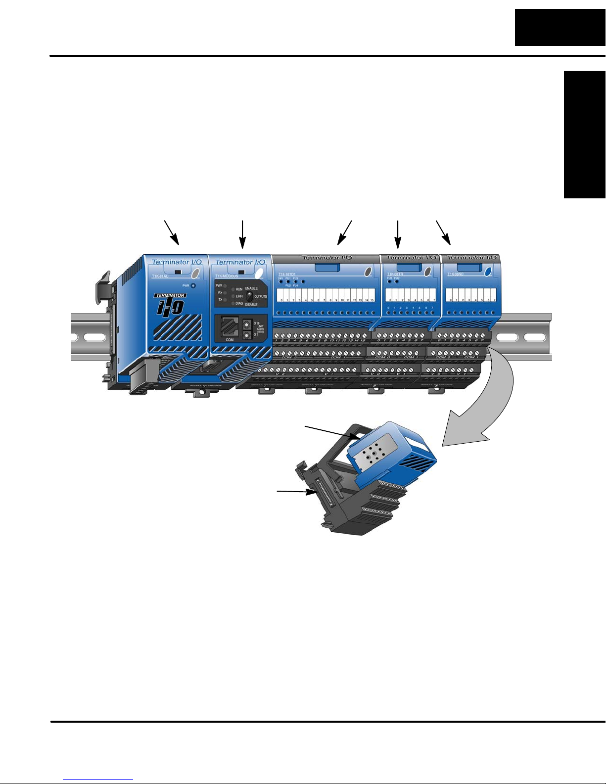
Terminator I/O is a modular system which combines the functions of terminal blocks
and I/O modules for distributed I/O. Each Terminator I/O system has the following
components: a Power Supply, a Base Controller, and one or more I/O Modules and
I/O bases.
1–5
Introduction
Introduction
Power Supply
Base
Controller
I/O Module
I/O Modules
Safety Guidelines
Installation and
I/O Base
Page 11

1–6
Introduction
T1K–MODBUS Base Controller
The T1K–MODBUS Base Controller is a slave module that functions as a controller
for Terminator I/O on a MODBUS network.
Introduction
MODBUS Base
Controller Features
Note: It is recommended to use the T1K–MODBUS Base Controller in a “scan
based” (polled) control system rather than in an “event–driven” control system. As a
slave, the Base Controller does not have the ability to report an error condition to the
MODBUS network master . Thus, polling a slave on a regular basis will detect a slave
error condition promptly, whereas an event–driven control system will not detect a
slave error condition until the next event is addressed to a slave in error.
The Base Controller has the following features:
• Status LEDs
• MODBUS Port
• Serial Port (RJ12)
• Unit Address Switches
• Output Enable/Disable Switch
• DIP Switch (located on right side of unit)
Output
Enable/Disable
Switch
Installation and
Safety Guidelines
Status LEDs
RJ12
Serial Port
Unit Rotary
Address
Switches
MODBUS Port
Page 12

T1K–MODBUS
Base Controller
Specifications
In This Chapter. . . .
— T1K–MODBUS Base Controller Specifications
— Setting the DIP Switches
— Setting the Rotary Address Switches
— MODBUS Port Pin–out and Wiring
1
2
— RJ12 Serial Port Pin–out and Wiring
Page 13

2–2
T1K–MODBUS Base Controller Specifications
Specifications
T1K–MODBUS
T1K–MODBUS Specifications
General
Operating Temperature 32° F to 131° F (0° C to 55° C)
Storage Temperature –4° F to 158° F (–20° C to 70° C)
Ambient Humidity 30% – 95% relative humidity (non–condensing)
Voltage Withstand 1500VAC, 1 minute (15–pin connector internal)
Insulation Resistance 500VDC, 10MΩ
Vibration Resistance MIL STD 810C, Method 514.2
Shock Resistance MIL STD 810C, Method 516.2
Noise Immunity NEMA (ICS3–304) Impulse noise 1µs, 1000V
FCC class A RFI (145MHz, 435MHz 10W, 10cm)
Atmosphere No corrosive gases
Environmental Pollution Level is 2.
Size 1.89”Wx3.15”Hx3.26”D (48Wx80Hx83D)mm
Weight 6.0 oz. (170 g)
Installation and
Safety Guidelines
MODBUS Port Specifications
Connector 15–pin female D–shell connector
Connection Port Type RS232C, RS–422/485
Protocol MODBUS RTU
Station Number 1 to F7h (247) Rotary Switch Setting
Number of I/O Points Inputs: 1024; Outputs: 1024
B
aud Rate (bps)
Communication Data 8 Bit (Fixed)
Start Bit 1 Bit (Fixed)
Stop Bit 1 Bit (Default), 2 Bit
Parity Bit ODD (Default) / EVEN / NONE;
Communication Timeout 500ms, 1s (Default), 2.5s, 5s, 10s, 25s, 60s
RTS On / RTS Off Delay Time 0 (Default) / 2 / 5 / 10 /50 /100 / 500 ms
Communication Status Indicators RUN, ERR, TX, RX
Module Status Indicators PWR, DIAG
300, 600, 1200, 2400, 4800, 9600, 19200,
3
8400 (Dip Switch 1–3 selectable)
Selectable with Dip Switch 4 ON (Option Mode)
Use T1K–MODBUS Setup Tool
Selectable with Dip SW 4 ON (Option Mode)
Use T1K–MODBUS Setup Tool
Selectable with Dip SW 4 ON (Option Mode)
Use T1K–MODBUS Setup Tool
Selectable with Dip SW 4 ON (Option Mode)
Use T1K–MODBUS Setup Tool
Page 14

T1K–MODBUS Specifications
(Green)
(Green)
(Green)
S
RJ12 Serial Port Specifications
Connector 6–pin female modular (RJ12 phone jack)
Connection Port Type RS232C
Protocol MODBUS RTU;
Use to configure the MODBUS port using the
T1K–MODBUS Setup Tool. Also use for firmware
upgrades.
Station Number 1 (Fixed)
Baud Rate 9600bps, 19200bps (Dip Switch 6 selectable)
Communication Data 8 Bit (Fixed)
Start Bit 1 Bit (Fixed)
Stop Bit 1 Bit (Fixed)
Parity Bit ODD (Fixed)
Base Controller I/O Specifications
Number of I/O Points (max.) Discrete: Inputs: 1024, Outputs: 1024
Analog: Inputs 64 Channels, Outputs 64 Channels
Number of Slots 1 to 31
Self–Diagnostics Watchdog Timer, Memory Check
I/O Module Type Supported Discrete Input, Discrete Output
Analog Input, Analog Output
Hot Swap Yes
Internal Power Consumption 250mA @ 5VDC
Allowable External Power Drop to 0V for 10ms max.
2–3
Specificaions
T1K–MODBUS
tatus Indicators
The status indicator LEDs on the Base Controller’s front panel have specific
functions which can help in programming and troubleshooting.
Indicator Status Description
PWR
(Green)
RX
TX
RUN
ERR ON Communication error
DIAG ON I/O system error
ON Power good
ON Data is being received by the Base Controller
OFF No data is being received by the Base Controller
ON Data is being transmitted by the Base Controller
OFF No data is being transmitted by the Base Controller
ON Starting communication to Master Module
OFF LED will turn OFF 1 second after failing to
communicate with master module
Flashing at
1 sec intervals
OFF I/O sytem good
ERR LED will begin flashing after the master stops
communicating with the Base Controller. The
Communication Time–out period can be set using
the T1K–MODBUS Setup Tool.
Safety Guidelines
Installation and
Page 15

2–4
DIP SW
T1K–MODBUS Specifications
Setting the DIP Switches
DIP Switch
Settings
Specifications
T1K–MODBUS
The T1K–MODBUS controller has an eight position DIP Switch which controls baud
rates, addressing modes, the state of the outputs in an error condition, etc. The DIP
Switch is located on the side of the unit, opposite the power supply.
Note: Be sure to look closely at the DIP Switch default settings below.
OFF ON
SW1
SW2
SW3
SW4
SW5
The DIP
Switch is on
this side.
Factory Default Settings Shown (all OFF)
SW6
SW7
SW8
MODBUS Port Baud Rate
Communication Setting Mode
Hold Outputs (on Comm. Error)
RJ12 Serial Port Baud Rate
MODBUS RTU Addressing Mode
CTS Control Enable/Disable
for RJ12 Serial Port
Installation and
Safety Guidelines
DIP Switches 1–3 select the MODBUS port baud rate.
SW 1–3 MODBUS Port Baud Rate
Baud Rate SW 1 SW2 SW3
300 bps OFF OFF OFF
600 bps ON OFF OFF
1200 bps OFF ON OFF
2400 bps ON ON OFF
4800 bps OFF OFF ON
9600 bps ON OFF ON
19200 bps OFF ON ON
38400 bps ON ON ON
Page 16

2–5
T1K–MODBUS Specifications
The Communications Setting mode, DIP Switch 4, enables some of the MODBUS
port communication parameters to be user set using the T1K–MODBUS Set Up
Tool. The following tables describe the default and option modes.
SW 4 Communication Setting Mode
OFF Default Mode
ON Option Mode
Default Mode:
The following table lists the MODBUS port default settings when DIP Switch 4 is in
the OFF position.
SW 4 OFF MODBUS Port / Default
Mode
Item Default Setting
Communication Data 8 Bit
Start Bit 1 Bit
Stop Bit 1 Bit
Parity Bit ODD
Communication Timeout 1s
RTS ON Delay Time 0ms
RTS OFF Delay Time 0ms
T1K–MODBUS
Specificaions
Option Mode:
The following items are user selectable using the T1K–MODBUS Set Up T ool* when
DIP Switch 4 is in the ON position.
SW 4 ON MODBUS Port / Option Mode
Item Default Setting
Communication Data 8 Bit (Fixed)
Start Bit 1 Bit (Fixed)
Stop Bit* 1 Bit / 2 Bit
Parity Bit* ODD / EVEN / NONE
Communication Timeout* 500ms, 1s, 2.5s, 5s, 10s, 25s, 60s
RTS ON Delay Time* 0ms, 2ms, 5ms, 10ms, 20ms, 50ms, 100ms, 500ms
RTS OFF Delay Time* 0ms, 2ms, 5ms, 10ms, 20ms, 50ms, 100ms, 500ms
Safety Guidelines
Installation and
Page 17

2–6
Specifications
T1K–MODBUS
T1K–MODBUS Specifications
The Hold Outputs DIP Switch 5 determines the slave outputs’ response to a
communications failure. If DIP switch 5 is in the ON position, the outputs in that slave
unit will hold their last state when a communication error occurs. If OFF, the outputs
in that slave unit will turn off in response to a communications error.
SW 5 Hold Outputs
OFF Turn OFF
ON Hold Last State
WARNING: Selecting “HOLD LAST STATE” means that outputs in that slave
will not be under program control in the event of a communications failure.
Consider the consequences to process operation carefully before selecting
this mode.
DIP Switch 6 selects the baud rate for the RJ12 serial port. All other serial port
communication parameters are fixed. The port defaults are listed in the
specifications tables in the beginning of this chapter.
Installation and
Safety Guidelines
SW 6 RJ12 Serial Port
Baud Rate
OFF 9600 bps
ON 19200 bps
DIP Switch 7 selects the T1K–MODBUS addressing mode. Select the OFF
position if the T1K–MODBUS is to be used with a MODBUS master that operates in
the 584/984 addressing mode. Select the ON position if the T1K–MODBUS is to be
used with a DirectLogic PLC CPU operating as the MODBUS master. The modes
are discussed in Chapter 3.
SW 7 MODBUS RTU
Addressing Mode
OFF 584/984 MODBUS Slave
ON DirectLogic PLC MODBUS Slave
DIP Switch 8 either enables or disables the CTS pin on the RJ12 serial port. Place
the switch in the ON position if the connected serial device requires RTS/CTS
control. Otherwise place the switch in the OFF position if only 3–wire
communication (TX, RX, GND) is required.
SW 8 CTS for RJ12 Serial Port
OFF Disable
ON Enable
Page 18

Setting the Rotary Address Switches
HEX Format
0 1 2 3 4 5 6 7 8 9 A B C D E F
The T1K–MODBUS unit address is set by the two rotary switches on the front of the
unit. Addresses are in hexadecimal format with valid address from 00 to F7, which is
equivalent to 0 t o 247 decimal. The addresses do not have to be sequential, but each
station address must be unique.
The top rotary switch is used to set the most significant digit of the HEX address. The
lower switch is used to set the least significant digit in the HEX address.
2–7
T1K–MODBUS Specifications
Converting HEX
Addresses to
Decimal
.
X10
UNIT
X1
ADRS
(HEX)
.
Eventhough the T1K–MODBUS unit address is set in HEX, it’s not difficult to
calculate the equivalent decimal address used by the MODBUS protocol.
To calculate the equivalent HEX address:
1) Divide the decimal address desired by 16. This provides the X10 HEX digit.
2) The remainder will be a number less than 16, resulting in a HEX number between
0–F. The remainder provides the X1 HEX digit. Two examples are given below.
T1K–MODBUS
Specificaions
Safety Guidelines
Installation and
0 1 2 3 4 5 6 7 8 9
60 decimal
60 ÷ 16 = 3
24 decimal
24 ÷ 16 = 1
10 11 12 13 14 15
with remainder of 12 = C
with remainder of 8 = 8
Decimal format
So 60 decimal = 3C
So 24 decimal = 18
HEX
HEX
Page 19

2–8
MODBUS Port Pin–out and Wiring
Specifications
T1K–MODBUS
RS–232C
Point-to-point
DTE Device
T1K–MODBUS Specifications
6
1
10
5
15-pin Female
D Connector
11
15
PC/PLC
MODBUS
Master
MODBUS Port Pin Descriptions
1 5V 5 VDC
2 TXD2 Transmit Data (RS232C)
3 RXD2 Receive Data (RS232C)
4 RTS2 Ready to Send (RS–232C)
5 CTS2 Clear to Send (RS–232C)
6 RXD2– Receive Data – (RS–422)
7 0V Logic Ground
8 0V Logic Ground
9 TXD2+ Transmit Data + (RS–422)
10 TXD2 – Transmit Data – (RS–422)
11 RTS2 + Request to Send + (RS–422)
12 RTS2 – Request to Send – (RS–422)
13 RXD2 + Receive Data + (RS–422)
14 CTS2 + Clear to Send + (RS422)
15 CTS2 – Clear to Send – (RS–422)
TXD
RXD
Signal GND
2 TXD
3 RXD
4RTS
5 CTS
70V
MODBUS
Port
RS–422
Network
Installation and
Safety Guidelines
RS–485
Network
RXD+
RXD–
TXD+
TXD–
Signal GND
PC/PLC
MODBUS
Master
PC/PLC
MODBUS
Master
The recommended cable
for RS422 is Belden
9729 or equivalent.
TXD+ / RXD+
TXD– / RXD–
Signal GND
9 TXD+
10 TXD–
13 RXD+
6 RXD–
11 RTS+
12 RTS–
14 CTS+
15 CTS–
70V
9 TXD+
13 RXD+
6 RXD–
10 TXD–
11 RTS+
14 CTS+
12 RTS–
15 CTS_
70V
Termination
Resistor on
last slave only
MODBUS
Port
Termination
Resistor on
last slave only
MODBUS
Port
Page 20

RJ12 Serial Port Pin–out and Wiring
Use D2–DSCBL
The Base Controller’s MODBUS port can be configured using the T1K–MODBUS
Setup Tool via the RJ12 serial port. The “Using the T1K–MODBUS Setup Tool”
chapter later in this manual discusses using the Setup Tool. The RJ12 port is also
used to upgrade the firmware in the base controller.
2–9
T1K–MODBUS Specifications
Modular Connector
to connect PC to
RJ12 Serial Port
6
1
6-pin Female
3 TXD
2 RXD
5 GND
7 RTS
8 CTS
RJ12 Serial Port Pin Descriptions
1 0V Power (–) connection (GND)
2 5V Power (+) connection
3 RXD Receive Data (RS232C)
4 TXD Transmit Data (RS232C
5 RTS Request to Send
6 CTS Clear to Send
4 TXD
3 RXD
1 GND
DIP Switch 8 in the OFF
Position to Disable CTS
T1K–MODBUS
Specificaions
6
1
Safety Guidelines
Installation and
Page 21

MODBUS RTU
Functions and
Addressing Modes
In This Chapter. . . .
— T1K–MODBUS RTU Function Codes
— Using T1K–MODBUS with DirectLogic PLC
— Using T1K–MODBUS with MODBUS 584/984
1
3
Page 22

3–2
MODBUS RTU Functions and Addressing Modes
MODBUS RTU Function Codes
MODBUS Function
Codes Supported
and Addressing Modes
MODBUS RTU Functions
The following MODBUS RTU functions are supported by the T1K–MODBUS base
controller.
MODBUS RTU
Function Code
01 Read Output Table
02 Read Input Table
03 Read Holding Registers (when addressing
mode is 584/984, this function is used to access analog output registers)
04 Read Input Registers (when addressing mode
is 584/984, this function is used to access
analog input registers)
05 Force Single Output
06 Preset Single Registers
07 Read Exception Status
08 Loop back / Maintenance
09 – 14 –
15 Force Multiple Outputs
16 Preset Multiple Registers
17 Report Device Type
18 – 64 –
65 not supported
66 not supported
68–70 not supported
72 not supported
73 – 127 –
Function
Installation and
Safety Guidelines
Page 23

MODBUS RTU Functions and Addressing Modes
DirectLogic Addressing Mode
3–3
Using the
T1K–MODBUS with
a DirectLogic PLC
Modbus Master
The DirectLogic Addressing mode is set by placing Dip Switch 7 in the ON position. The
following memory locations are supported by the T1K–MODBUS base controller in the
DirectLogic Addressing Mode.
• X0 – X1777 Discrete Inputs
• Y0 – Y1777 Discrete Outputs
• V0 – V177 Analog Inputs
• V1400 – V1577 Analog Outputs
T1K–Modbus
Memory Type
For Discrete Data Type
Inputs (X) 1024 X0 – X1777 V40400 – V40477
Outputs (Y) 1024 Y0 – Y1777 V40500 – V40577
For Word (16–bit) Data Types
Analog Input
Data Register (V)
Analog Output
Data Registers (V)
QTY.
(Dec.)
128 V0 – V177
128 V1400 – V1577
PLC Range
(Octal)
V Memory Range
MODBUS RTU Functions
and Addressing Modes
Safety Guidelines
Installation and
Page 24

3–4
Data Type
Coil
Input
Modbus Data Type
Input Register
Hold Register
MODBUS RTU Functions and Addressing Modes
584/984 Addressing Mode
Note: ModScan32 is a Windows based application program that can be used as a
MODBUS master to access and change data points in a connected slave device
(T1K–MODBUS). The utility is ideally suited for quick and easy testing of MODBUS
network slave devices. Visit ww w.win–tech.com to download a free ModScan32 trial
demo and for more information on ModScan32.
Using the
T1K–MODBUS
with a 584 / 984
MODBUS Master
and Addressing Modes
MODBUS RTU Functions
The 584 / 984 Addressing mode is set by placing Dip Switch 7 in the OFF position. The
following decimal memory locations are supported by the T1K–MODBUS base controller in
the 584 / 984 Addressing Mode.
1 – 1024 Discrete Outputs
•
• 10001 – 11024 Discrete Inputs
• 30001 – 30128 Analog Input Registers
• 30201 – 30264 Bit Input Registers
• 40001 – 40128 Analog Output Registers
• 40201 – 40264 Bit Output Registers
Modbus
Range (Decimal) Points Memory Type
1 – 1024 1024 Discrete Output
1025 – 9999 – not supported
10001 – 11024 1024 Discrete Input
11025 – 19999 – not supported
Range (Decimal) Words
T1K–MODBUS
V Memory Range
Channel
(16– bit)
(32– bit)
Memory Type
Analog Input 30001 – 30128 128 64 Analog Input Register
Input Register 30129 – 38999 – – not supported
Installation and
Safety Guidelines
Bit Input Register 30201 – 30264 64 – Discrete Input Bit
Input Register 39129 – 39999 – – not supported
Analog output 40001 – 40128 128 64 Analog Output
Hold Register 40129 – 40200 – – not supported
Bit Output
Register
Hold Register 40265 – 49000 – – not supported
Hold Register 49001 – 49128 128 – Special Register
Hold Register 49129 – 49999 – – not supported
Register
Register
40201 – 40264 64 Discrete Output Bit
Register
Page 25

Using the
T1K–MODBUS
Setup Tool
In This Chapter . . . .
— Configuring the T1K–MODBUS Port
1
4
Page 26

4–2
Using the T1K–MODBUS Set Up Tool
Configuring the T1K–MODBUS Port
T1K–MODBUS Setup Tool (included with this manual) can be used to configure some of the
MODBUS port communication parameters via the RJ12 serial port. The T1K–MODBUS DIP
switch 4 must be in the ON position in order to use the Setup Tool to configure the
MODBUS port parameters. The configurable parameters include the Stop Bit, Parity Bit, On
Delay Time, Off Delay Time and Communication Time–out. If the DIP switch is in the Off
position, the factory defaults will apply. The Tool allows the T1K–MODBUS Firmware version,
Rotary Address Switches and DIP switches to be read only.
Installing the
Setup Tool
The Setup Tool can run on Windows 95/98/2000/MEt or Windows NTt (but not
Windows 3.1xt). The Tool is included with this manual on three 3.5” diskettes. It is
also available for download from the AutomationDirect web site
(www.automationdirect.com). The installation process places the files in the
C:\Program Files\T1K–MODBUS Setup Tool directory (default).
Place disk 1 of 3 in Drive A or Drive B. Click on the Windows Start button and then
select Run. Type in the path and filename (ex. A:\setup), or click on the Browse
button to find the directory and filename (ex. if the Setup Tool was downloaded from
the web). A series of windows will step through the installation process for disks 1, 2
and 3.
Launching the
Setup Tool
Set Up Tool
Using the T1K–MODBUS
Use the Windows Start menu Programs>T1K–MODBUS Setup Tool>
T1K–MODBUS Setup Tool as shown below to launch the Setup Tool.
Page 27

Using the T1K–MODBUS Set Up Tool
4–3
Selecting the PC
Comm Port
Configuring the
MODBUS Port
Select the PC port that will be used to connect to the T1K–MODBUS base controller’s RJ12
serial port.
The following window will be displayed when the Tool is communicating with the base
controller’s RJ12 serial port.
Using The T1K–MODBUS Installation and
Set Up Tool
T1K–MODBUS
Firmware Version
READ ONLY
Rotary Address Switches
DIP Switch Settings
These MODBUS Port
Parameters can be
configured
Write the New Settings to
the base controller
Safety Guidelines
Page 28

Appendix A
I/O Module
Hot Swap
In This Appendix. . . .
— T1K–MODBUS I/O Module Hot Swap Feature
1
A
Page 29

A–2
T1K–MODBUS I/O Module Hot Swap Feature
Appendix AAppendix B
I/O Module Hot Swap
The “Hot Swap” feature allows Terminator I/O modules to be replaced with
Terminator I/O system power ON. Be careful not to touch the terminals with your
hands or any conductive material to avoid the risk of personal injury or equipment
damaged. Always remove power if it is equally convenient to do so.
I/O Module Hot Swap
Check External
24VDC Wiring
Before Hot
Swapping!
WARNING: Only authorized personnel fully familiar with all aspects of the
application should replace an I/O module with system power ON.
The following module types can be “Hot Swapped”.
Module
Power Supply No
Base Controller No
I/O Modules (discrete / analog) Yes
Before “Hot Swapping” an analog I/O module or a DC output module in a
Terminator I/O system, make sure that each of the analog I/O and DC output
module’s 24VDC and 0VDC base terminals are wired directly to the external
power supply individually (see diagram below). If the external 24VDC / 0VDC is
jumpered from base to base in a daisy chain fashion, and an analog I/O or DC output
module is removed from its base, the risk of disconnecting the external 24VDC to the
subsequent I/O modules exists.
Appendix E
Do not jumper
modules together
creating 24VDC
bus for Hot Swap.
Wire each analog I/O and DC
output module independently
to the external power supply.
Page 30

Hot Swap:
I/O Module
Replacement
A–3
I/O Module Hot Swap
I/O Module Hot Swap
The following steps explain how to “Hot Swap” an I/O module.
Appendix A
1. Remove I/O module from base. (If necessary, refer to the Terminator I/O
Installation & I/O Manual for steps on removing an I/O module).
2. The T1K–MODBUS DIAG LED will turn ON.
3. Install a new I/O module with the exactly the same part number.
4. Verify that the T1K–MODBUS Base Controller LEDs have returned to normal.
Outputs
Enable/Disable
Switch
A feature that may be used in a non–continuous process application is the Outputs
Enable/Disable switch. The switch is located on the front of the T1K–MODBUS base
controller. This feature may be used at a convenient time during the process
application to replace an I/O module.
When the switch is in the Disable position:
Sall outputs are Disabled (OFF)
Sthe Base Controller’s output status memory is cleared
Sthe Base Controller ignores any outputs command from the Master Module
Page 31

Appendix B:
Analog Output
Module Configuration
In This Appendix. . . .
— Analog Output Module Control Byte
1
B
Page 32

B–2
Size
Read/Write
Analog Output Module Control Byte
Appendix BAppendix B
Analog Output Module Configuration
The Terminator I/O analog output modules are configured using the Module
Control Byte located in the most significant byte of the most significant word of
channel 1 of the module. The “I/O Memory Map and Analog Module Resolution”
chapter in the Terminator Installation and I/O Manual (T1K–INST–M) covers
memory mapping for the Terminator I/O modules.
Analog Output Module
Channel 1 Memory Map
of 8&16-Channel Analog Output Module
(T1F–08DA, T1F–016DA)
Decimal Bit 07 06 05 04 03 02 01 00
Octal Bit 07 06 05 04 03 02 01 00
Analog Value Channel 1 Write Byte 1
Analog Value Channel 1 Write Byte 2
not used Byte3
Module Control Byte Write Byte 4
Module Control Byte of 8&16-Channel Analog Output Module
(T1F–08DA, T1F–16DA)
Decimal Bit 31 30 29 28 27 26 25 24
Octal Bit 37 36 35 34 33 32 31 30
Outputs Enable
Bit 24
Bit 25
Bit 26
Bit 27
Bit 28 – 31 Reserved for system use –
0 = All outputs OFF
1 = All outputs Enabled
Unipolar / Bipolar
0 = Unipolar selected
1 = Bipolar selected
5V / 10V Range
0 = 5V range
1 = 10V range
0 – 20mA / 4–20mA Range
0 = 0 – 20mA range
1 = 4 – 20mA range
Write
Write
Write
Write
Appendix E
 Loading...