

Page 1

Errata Sheet
Errata Sheet
This Errata Sheet contains corrections or changes
made after the publication of this manual.
Product Family: Terminator I/O
Manual Number T1K-DEVNETS-M
Revision and Date 1st Edition; November 2001
Changes to Chapter 2. Installing the T1K–DEVNETS Base Controller
Page 2-9. Configuring the Controller; Status Indicators
Replace the top portion of the table [MS (Module Status) Indicator] with the table below.
Two new rows were added for Flashing Green and Flashing Red.
No changes were made to the lower portion of the table [NS (Network Status) Indicator].
MS (Module Status) Indicator
Indication Status
OFF No power to Controller. Check wiring.
ON (Green) Power applied to Controller, no fault
ON (Red) Critical Controller Fault
Flashing Green In Firmware Update Mode
Date: December 2018
Flashing Red I/O system error
Missing module error
New module present error
I/O diagnostic error
Page 1 of 1
Page 2

T1K–DEVNETS
DeviceNet Base
Controller
User Manual
Manual Number T1K–DEVNETS–M
Page 3

WARNING
Thank you for purchasing automation equipment from Automationdirect.com. We want your new DirectLOGIC
automation equipment to operate safely. Anyone who installs or uses this equipment should read this publication (and
any other relevant publications) before installing or operating the equipment.
To minimize the risk of potential safety problems, you should follow all applicable local and national codes that regulate
the installation and operation of your equipment. These codes vary from area to area and usually change with time. It is
your responsibility to determine which codes should be followed, and to verify that the equipment, installation, and
operation are in compliance with the latest revision of these codes.
At a minimum, you should follow all applicable sections of the National Fire Code, National Electrical Code, and the
codes of the National Electrical Manufacturer’s Association (NEMA). There may be local regulatory or government
offices that can also help determine which codes and standards are necessary for safe installation and operation.
Equipment damage or serious injury to personnel can result from the failure to follow all applicable codes and
standards. We do not guarantee the products described in this publication are suitable for your particular application,
nor do we assume any responsibility for your product design, installation, or operation.
Our products are not fault–tolerant and are not designed, manufactured or intended for use or resale as on–line control
equipment in hazardous environments requiring fail–safe performance, such as in the operation of nuclear facilities,
aircraft navigation or communication systems, air traffic control, direct life support machines, or weapons systems, in
which the failure of the product could lead directly to death, personal injury, or severe physical or environmental
damage (”High Risk Activities”). Automationdirect.com specifically disclaims any expressed or implied warranty of
fitness for High Risk Activities.
For additional warranty and safety information, see the Terms and Conditions section of our Desk Reference. If you
have any questions concerning the installation or operation of this equipment, or if you need additional information,
please call us at 770–844–4200.
This publication is based on information that was available at the time it was printed. At Automationdirect.com we
constantly strive to improve our products and services, so we reserve the right to make changes to the products and/or
publications at any time without notice and without any obligation. This publication may also discuss features that may
not be available in certain revisions of the product.
Trademarks
This publication may contain references to products produced and/or offered by other companies. The product and
company names may be trademarked and are the sole property of their respective owners. Automationdirect.com
disclaims any proprietary interest in the marks and names of others.
Copyright 2001, Automationdirect.com Incorporated
All Rights Reserved
No part of this manual shall be copied, reproduced, or transmitted in any way without the prior, written consent of
Automationdirect.com Incorporated. Automationdirect.com retains the exclusive rights to all information
included in this document.
Page 4

AVERTISSEMENT
Nous vous remercions d’avoir acheté l’équipement d’automatisation de Automationdirect.comE. Nous tenons à ce que
votre nouvel équipement d’automatisation DirectLOGIC fonctionne en toute sécurité. Toute personne qui installe ou
utilise cet équipement doit lire la présente publication (et toutes les autres publications pertinentes) avant de l’installer ou de
l’utiliser.
Afin de réduire au minimum le risque d’éventuels problèmes de sécurité, vous devez respecter tous les codes locaux et
nationaux applicables régissant l’installation et le fonctionnement de votre équipement. Ces codes diffèrent d’une région à
l’autre et, habituellement, évoluent au fil du temps. Il vous incombe de déterminer les codes à respecter et de vous assurer
que l’équipement, l’installation et le fonctionnement sont conformes aux exigences de la version la plus récente de ces
codes.
Vous devez, à tout le moins, respecter toutes les sections applicables du Code national de prévention des incendies, du
Code national de l’électricité et des codes de la National Electrical Manufacturer’s Association (NEMA). Des organismes de
réglementation ou des services gouvernementaux locaux peuvent également vous aider à déterminer les codes ainsi que
les normes à respecter pour assurer une installation et un fonctionnement sûrs.
L’omission de respecter la totalité des codes et des normes applicables peut entraîner des dommages à l’équipement ou
causer de graves blessures au personnel. Nous ne garantissons pas que les produits décrits dans cette publication
conviennent à votre application particulière et nous n’assumons aucune responsabilité à l’égard de la conception, de
l’installation ou du fonctionnement de votre produit.
Nos produits ne sont pas insensibles aux défaillances et ne sont ni conçus ni fabriqués pour l’utilisation ou la revente en tant
qu’équipement de commande en ligne dans des environnements dangereux nécessitant une sécurité absolue, par
exemple, l’exploitation d’installations nucléaires, les systèmes de navigation aérienne ou de communication, le contrôle de
la circulation aérienne, les équipements de survie ou les systèmes d’armes, pour lesquels la défaillance du produit peut
provoquer la mort, des blessures corporelles ou de graves dommages matériels ou environnementaux (”activités à risque
élevé”). La société Automationdirect.comE nie toute garantie expresse ou implicite d’aptitude à l’emploi en ce qui a trait
aux activités à risque élevé.
Pour des renseignements additionnels touchant la garantie et la sécurité, veuillez consulter la section Modalités et
conditions de notre documentation. Si vous avez des questions au sujet de l’installation ou du fonctionnement de cet
équipement, ou encore si vous avez besoin de renseignements supplémentaires, n’hésitez pas à nous téléphoner au
770–844–4200.
Cette publication s’appuie sur l’information qui était disponible au moment de l’impression. À la société
Automationdirect.comE, nous nous efforçons constamment d’améliorer nos produits et services. C’est pourquoi nous
nous réservons le droit d’apporter des modifications aux produits ou aux publications en tout temps, sans préavis ni quelque
obligation que ce soit. La présente publication peut aussi porter sur des caractéristiques susceptibles de ne pas être offertes
dans certaines versions révisées du produit.
La présente publication peut contenir des références à des produits fabriqués ou offerts par d’autres entreprises. Les
désignations des produits et des entreprises peuvent être des marques de commerce et appartiennent exclusivement à
leurs propriétaires respectifs. Automationdirect.comE nie tout intérêt dans les autres marques et désignations.
Copyright 2001, Automationdirect.comE Incorporated
Nulle partie de ce manuel ne doit être copiée, reproduite ou transmise de quelque façon que ce soit sans le consentement
préalable écrit de la société Automationdirect.comE Incorporated. Automationdirect.comE conserve les droits
exclusifs à l’égard de tous les renseignements contenus dans le présent document.
Marques de commerce
Tous droits réservés
Page 5

1
Manual Revisions
If you contact us in reference to this manual, be sure to include the revision number.
Title: Terminator I/O DeviceNet Base Controller User Manual
Manual Number: T1K–DEVNETS–M
Edition Date Description of Changes
Original 11/01 Original issue
Page 6

Table of Contents
Chapter 1: Getting Started
Introduction 1–2. . . . . . . . . . . . . . . . . . . . . . . . . . . . . . . . . . . . . . . . . . . . . .
The Purpose of this Manual 1–2. . . . . . . . . . . . . . . . . . . . . . . . . . . . .
Supplemental Manuals 1–2. . . . . . . . . . . . . . . . . . . . . . . . . . . . . . . . .
Who Should Read this Manual 1–2. . . . . . . . . . . . . . . . . . . . . . . . . . .
Technical Support 1–2. . . . . . . . . . . . . . . . . . . . . . . . . . . . . . . . . . . . . .
Symbols Used 1–3. . . . . . . . . . . . . . . . . . . . . . . . . . . . . . . . . . . . . . . . .
Introduction to DeviceNet 1–4. . . . . . . . . . . . . . . . . . . . . . . . . . . . . . . . .
DeviceNet Concepts 1–4. . . . . . . . . . . . . . . . . . . . . . . . . . . . . . . . . . . .
The ODVA 1–4. . . . . . . . . . . . . . . . . . . . . . . . . . . . . . . . . . . . . . . . . . . .
Terminator I/O System 1–5. . . . . . . . . . . . . . . . . . . . . . . . . . . . . . . . . . . .
Mini Glossary 1–5. . . . . . . . . . . . . . . . . . . . . . . . . . . . . . . . . . . . . . . . . .
T1K–DEVNETS Base Controller 1–6. . . . . . . . . . . . . . . . . . . . . . . . . . .
T1K–DEVNETS Base Controller Features 1–6. . . . . . . . . . . . . . . . .
ii
Chapter 2: Installing the T1K–DEVNETS
Base Controller
Installing the T1K–DEVNETS 2–2. . . . . . . . . . . . . . . . . . . . . . . . . . . . . .
Mounting on DIN Rail 2–2. . . . . . . . . . . . . . . . . . . . . . . . . . . . . . . . . . .
Connecting the Controller to a Power Supply 2–2. . . . . . . . . . . . . .
Setting the Node Address 2–3. . . . . . . . . . . . . . . . . . . . . . . . . . . . . . .
Connecting the Components on the DIN Rail 2–3. . . . . . . . . . . . . .
Removing I/O Modules from the Base 2–4. . . . . . . . . . . . . . . . . . . .
Assembling the I/O Modules and Bases 2–4. . . . . . . . . . . . . . . . . . .
DIP Switch Settings 2–5. . . . . . . . . . . . . . . . . . . . . . . . . . . . . . . . . . . .
Parameter initialization values 2–6. . . . . . . . . . . . . . . . . . . . . . . . . . .
T1K–DEVNETS setup parameters 2–6. . . . . . . . . . . . . . . . . . . . . . .
Wiring the Controller to a DeviceNet Network 2–7. . . . . . . . . . . . . .
Serial Port (RS–232) 2–7. . . . . . . . . . . . . . . . . . . . . . . . . . . . . . . . . . .
Configuring the Controller 2–8. . . . . . . . . . . . . . . . . . . . . . . . . . . . . . . .
Configuring the DeviceNet Base Controller 2–8. . . . . . . . . . . . . . . .
Status Indicators 2–9. . . . . . . . . . . . . . . . . . . . . . . . . . . . . . . . . . . . . . .
Outputs Switch 2–9. . . . . . . . . . . . . . . . . . . . . . . . . . . . . . . . . . . . . . . .
Master/Slave Communications 2–10. . . . . . . . . . . . . . . . . . . . . . . . . . .
Terminator I/O Backplane Communications 2–11. . . . . . . . . . . . . . .
I/O Module Memory Map 2–11. . . . . . . . . . . . . . . . . . . . . . . . . . . . . .
Appendix A: Specification
Specifications A–2. . . . . . . . . . . . . . . . . . . . . . . . . . . . . . . . . . . . . . . . . . .
Page 7

Appendix B: Tables
Data Input and Output Tables B–2. . . . . . . . . . . . . . . . . . . . . . . . . . . .
Input Register Object Class (107) B–2. . . . . . . . . . . . . . . . . . . . . . . .
Output Register Object Class (108) B–4. . . . . . . . . . . . . . . . . . . . . . .
Data Register Range B–5. . . . . . . . . . . . . . . . . . . . . . . . . . . . . . . . . . .
I/O Diagnostic Information B–6. . . . . . . . . . . . . . . . . . . . . . . . . . . . . . .
DIP Switch SW4 . . . . . . . . . . . . . . . . . . . . . . . . . . . . . . . . . . . B–6
System Information Object Specifications B–7. . . . . . . . . . . . . . . . .
Appendix C: Image Table Mapping
Image Table Mapping C–2. . . . . . . . . . . . . . . . . . . . . . . . . . . . . . . . . . . .
Appendix D: T1K–DEVNETS Think & Do
Setup
T1K–DEVNETS Think & Do Setup D–2. . . . . . . . . . . . . . . . . . . . . . . . .
T & D Studio setup for PC control D–2. . . . . . . . . . . . . . . . . . . . . . .
Appendix E: T1K–DEVNETS and
RSNetWorxt Setup
Setup T1K–DEVNETS with RSNetWorxt E–2. . . . . . . . . . . . . . . . . .
RSLinx E–2. . . . . . . . . . . . . . . . . . . . . . . . . . . . . . . . . . . . . . . . . . . . . . .
RSLogix E–6. . . . . . . . . . . . . . . . . . . . . . . . . . . . . . . . . . . . . . . . . . . . . .
Configure T1K–DEVNETS with RSNetWorx
Using the EDS file E–8. . . . . . . . . . . . . . . . . . . . . . . . . . . . . . . . . . . . . .
Go on line E–11. . . . . . . . . . . . . . . . . . . . . . . . . . . . . . . . . . . . . . . . . . . .
Set up I/O parameters E–12. . . . . . . . . . . . . . . . . . . . . . . . . . . . . . . .
Map the nodes E–15. . . . . . . . . . . . . . . . . . . . . . . . . . . . . . . . . . . . . . .
Set Class Instance Attribute E–18. . . . . . . . . . . . . . . . . . . . . . . . . . .
t E–8. . . . . . . . . . . .
Page 8

Getting Started
In This Chapter. . . .
— Introduction
— Introduction to DeviceNet
— Terminator I/O System
— T1K–DEVNETS DeviceNet Base Controller
1
1
Page 9
1–2
Introduction
Getting Started
The Purpose of
this Manual
Getting Started
Supplemental
Manuals
Who Should Read
this Manual
This manual describes the installation and
operation of the Terminator I/O DeviceNet
Base Controller (T1K–DEVNETS).
The following manuals are essential to the proper use of your Terminator I/O
DeviceNet Adapter.
• Terminator Installation and I/O Manual part number T1K–INST–M
This manual contains very important information, including a complete
I/O Module Memory Map. The Memory Map is crucial in designing and
implementing a Terminator I/O system.
• The PLC/PC software manual
• The DeviceNet software (if separate) manual
• The DeviceNet Scanner (or Master) manual
If you have a working knowledge of the DeviceNet network, the DeviceNet software
and PLC or PC which you are using, this manual will help you configure and install
your T1K–DEVNETS DeviceNet Base Controller.
Technical Support
Installation and
Safety Guidelines
We strive to make our manuals the best in the industry and rely on your feedback in
reaching our goal. If you cannot find the solution to your particular application, or, if
for any reason you need additional technical assistance, please call us at
770–844–4200.
Our technical support team is glad to work with you in answering your questions.
They are available weekdays from 9:00 a.m. to 6:00 p.m. Eastern Time. We also
encourage you to visit our website where you can find technical and nontechnical
information about our products and our company.
www.automationdirect.com
Page 10
Introduction
1–3
Symbols Used
Key Topics for
Each Chapter
The “light bulb” icon in the left-hand margin indicates a tip or shortcut.
The “note pad” icon in the left–hand margin indicates a special note.
The “exclamation mark” icon in the left-hand margin indicates a warning or caution.
These are very important because the information may help you prevent serious
personal injury or equipment damage.
The beginning of each chapter will list the
key topics that can be found in that
chapter.
1
Getting Started
Safety Guidelines
Installation and
Page 11

1–4
Introduction to DeviceNet
Getting Started
DeviceNet
Concepts
Getting Started
DeviceNet is a low-level network designed to connect factory-floor devices to control
systems. There are a host of manufacturers of DeviceNet products, offering an array
of products including sensors, motor drives and starters, PLCs, pushbuttons,
remote I/O systems, etc.
Here are some DeviceNet concepts you may find helpful.
• DeviceNet supports various communication structures including Peer to
Peer, Multi-master and Master/Slave. The T1K–DEVNETS uses the
predefined Master/Slave connection.
• DeviceNet has two types of messaging: Explicit Messaging and I/O
Messaging.
• Explicit Messaging is low priority, not time-critical and usually
for configuration/diagnostic purposes.
• I/O Messaging is time-critical and high priority
for I/O data transfer. I/O Messaging comes in four types:
• Strobed
• Polled (The T1K–DEVNETS only supports Polled.)
• Change of State (or COS)
• Cyclic
• A single DeviceNet network is limited to 64 nodes. A node can be a
single-bit device, such as a limit switch, or a remote I/O slave with
several I/O modules, such as the T1K–DEVNETS. The Master
(Scanner) is usually assigned to node address 0, and many Slave
devices have a factory default node address of 63.
• DeviceNet has the following data rates (with maximum bus lengths):
• 125 kbps (bus length = 500m max.)
• 250 kbps (bus length = 250m max.)
• 500 kbps (bus length = 100m max.)
• The 24V DeviceNet power supply must be grounded at only one point.
The V– terminal must be tied to Protective Earth Ground at the power
supply only.
Installation and
The ODVA
Safety Guidelines
The DeviceNet standard is maintained by the ODVA (Open DeviceNet Vendor
Association, Inc.). Contact the ODVA for detailed information about DeviceNet.
Open DeviceNet Vendor Association, Inc.
20423 State Road 7
Suite 499
Boca Raton, FL 33498
Phone: (954) 340–5412
Fax: (954) 340–5413
Internet: www.odva.org
Email: odva@powerinternet.com
Page 12
Introduction
1–5
Terminator I/O System
Terminator I/O is a modular system which combines the functions of terminal blocks
and I/O modules for distributed I/O. Each Terminator I/O system has the following
components: a Power Supply, a Base Controller, and one or more I/O Module(s).
DeviceNet
Power Supply
Base
Controller
Getting Started
I/O Modules
Mini Glossary
I/O Module
I/O Base
Below is a small glossary of terms used in this manual.
Scanner or Master The DeviceNet Master of which the
T1K–DEVNETS is a slave. This can be either a
PLC module or a card in your PC.
Controller or Slave Short for the T1K–DEVNETS Base Controller.
The controller is also referred to as a Network
Interface Module elsewhere.
Node Address or MAC ID The unique device address on a DeviceNet
network. There are a maximum of 64 total (0–63).
Usually the scanner is node 0.
Safety Guidelines
Installation and
Page 13

1–6
T1K–DEVNETS Base Controller
T1K–DEVNETS
Getting Started
Base Controller
Features
Getting Started
The T1K–DEVNETS Base Controller is a slave module that functions as a controller
for Terminator I/O on a DeviceNet network.
The Controller has the following features:
• Status LEDs (Module and Network)
• Serial Port
• Node Address Switches
• Output Enable Switch
• DeviceNet Connector
Clip Arm
Installation and
Safety Guidelines
Output
Enable/Disable
Switch
Node Address
Switches
Status LEDs
Serial Port
DeviceNet
Connector
Locking Tab
Page 14

Installing the
T1K–DEVNETS Base
Controller
In This Chapter. . . .
— Installing the T1K–DEVNETS Base Controller
— Configuring the Controller
— Master/Slave Communications
— Terminator I/O Backplane Communications
1
2
Page 15
2–2
Installing the T1K–DEVNETS Base Controller
Installing the T1K–DEVNETS
Mounting
on DIN Rail
2
Base Controller
Installing the DeviceNet
Connecting the
Controller to a
Power Supply
Installation and
Safety Guidelines
3
1
NOTE: Do not force the base controller onto the DIN rail.
Due to slight size variations in different manufacturer’s DIN
rail, it may be necessary to first unlatch the locking tab,
rotate the module into place, then latch the locking tab.
1. Make sure the locking tab is in the latched position (pushed in).
2. Hook upper tab over upper flange of DIN rail.
3. Tilt the unit toward DIN rail until it snaps securely to DIN rail.
Slide the controller onto the DIN rail until the clip arm attaches securely to the
power supply.
WARNING: Power to the T1K Power Supply must be disconnected before installing
or removing the T1K–DEVNETS. Failure to disconnect power could result in serious
damage to the module, to the power supply or both.
Page 16
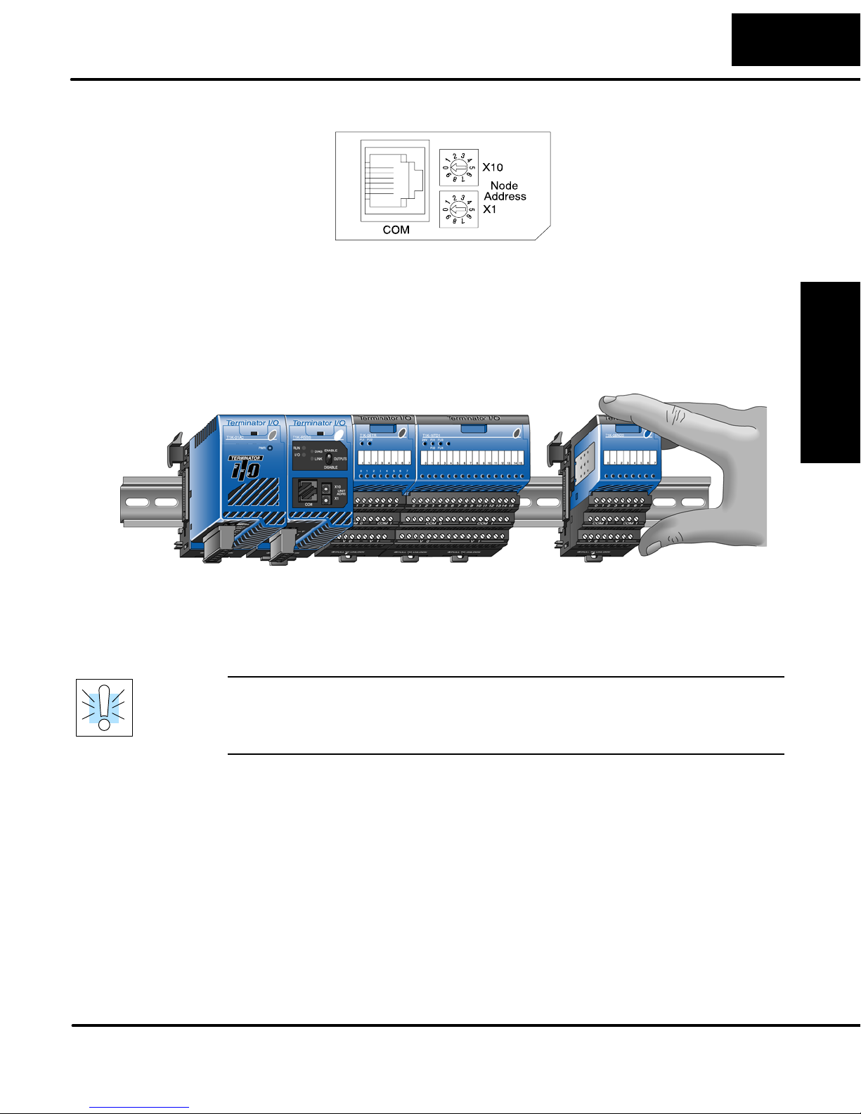
Setting the Node
Address
Connecting the
Components on
the DIN Rail
Installing the T1K–DEVNETS Base Controller
Use a small flat screwdriver to set the Node Address to an
available Node Address (or MAC ID), from 0 – 63. Note that X10
represents the tens place and X1 represents the units place.
2–3
Installing the DeviceNet
Base Controller
Slide the module assembly onto the DIN rail until the
clip arm attaches securely to the adjacent module.
WARNING: Again, be sure that the power to the T1K Power Supply is
disconnected before installing or removing the module assemby. Failure to
disconnect power could result in serious damage to the modules, to the power
supply or to the entire assembly.
Safety Guidelines
Installation and
Page 17
2–4
Installing the T1K–DEVNETS Base Controller
Removing I/O
Modules from
the Base
Base Controller
Installing the DeviceNet
To remove the module from the base, grip the center of the base arm and rotate
outward releasing the module.
To remove the module assembly from the DIN rail, lift the clip arm up and slide the
module assembly away from the adjacent module. Pull the locking tab down (out)
and lift the assembly off the DIN rail. Refer to the “I/O Module Hot Swap Feature”,
page 3–17, in the Terminator I/O Installation and I/O Manual (T1K–INST–M), to
remove an I/O module with Terminator I/O system power ON.
Assembling the
I/O Modules
and Bases
Installation and
Safety Guidelines
1
3
2
Insert Module into Base
1. Pull base arm back to allow space for module to enter base
2. Align module slides with base track
3. Press module firmly into base
Page 18
Installing the T1K–DEVNETS Base Controller
e
2–5
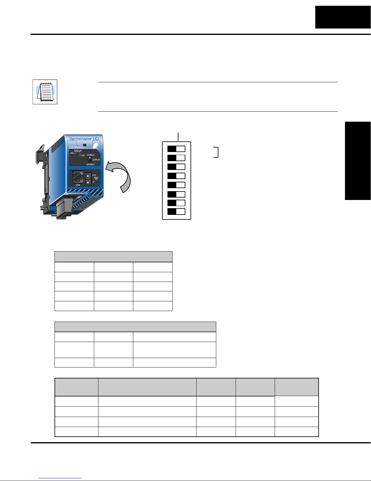
DIP Switch
Settings
The T1K–DEVNETS controller has a DIP Switch which is used to set baud rates,
initializing and the state of outputs if a communication error occurs. The DIP Switch
is located on the side of the unit, opposite the power supply.
Note: Be sure to look closely at the default settings below. If you are connecting to
an existing DeviceNet network, you may need to change the DeviceNet Baud Rate
on your T1K–DEVNETS. The factory default baud rate is 125kbps.
DIP SW
OFF ON
SW1
DeviceNet Baud Rate
SW2
16/32 Bit/Channel Analog Selection
I/O Polling Diagnostics Enable/Disabl
Hold Outputs (on Comm. Error)
Maintenace Port Baud Rate
Maintenace Port Protocol Selection
Maintenace Port RTS/CTS
Control Enable/Disable
The DIP
Switch is on
this side.
SW3
SW4
SW5
SW6
SW7
SW8
Factory Default Settings Shown (all OFF)
Installing the DeviceNet
Base Controller
Set the DeviceNet baud rate.
DeviceNet Baud Rate
Baud Rate SW1 SW2
125 kbps OFF OFF
250 kbps ON OFF
500 kbps OFF ON
Reserved ON ON
Analog Bit Selection
No. of Bits SW3 Description
32 OFF Defaults to original 2–word
(32 bits) per analog channel.
16 ON N/A
Parameter Table
System
Description SW3=OFF SW3=ON Comment
V–Memory
V7614 Input register: Starting location V3000 V3000 Read only
V7615 Input Register: Number of bytes 58 Bytes 128 Bytes Read only
V7616 Output Register: Starting location V3100 V3100 Read only
V7617 Output Register: Number of bytes 52 Bytes 128 Bytes Read only
Safety Guidelines
Installation and
Page 19
2–6
Installing the T1K–DEVNETS Base Controller
Disable I/O Polling Diagnostics *
I/O Diagnostics SW 4
Enable OFF
Disable ON
* If DIP Switch 4 is in the OFF (default) position, you must allow for two additional
bytes on the input (RX) and two additional bytes on the output (TX) for Terminator I/O
diagnostic functions. Refer to page B–6 for the I/O diagnostic information.
Base Controller
Installing the DeviceNet
T1K–DEVNETS
setup parameters
Parameter Table
System
V–Memory
V7614 Input register:
V7615 Input Register:
V7616 Output Register:
Installation and
Safety Guidelines
V7617 Output Register:
Hold Outputs
Outputs SW5 Baud Rate SW 6 Protocol SW7
Turn Off OFF
Hold ON 19200 bps ON ASCII ON
Maintenance Port RTS/CTS Control
SW 8 RTS/CTS Description
OFF Disable RTS/CTS not available
ON Enable RTS/CTS available
Maintenance Port Baud
Rate
9600 bps OFF Normal OFF
Maintenance Port
Protocol Selection
Setting up the parameters of the T1K–DEVNETS will set the values to special
registers when power is applied to it. When the registers are set to the correct range,
their parameters will be stored in EEPROM, and the parameters will be retained
when power is turned off. Refer to the following table.
Description Value when the scratch
Range
pad is initialized
V3000 V0 – V7377
Starting location
58 Bytes 0 – 128
Number of bytes
V3100 V0 – V7377
Starting location
52 Bytes 0 – 128
Number of bytes
Page 20
Installing the T1K–DEVNETS Base Controller
2–7
Wiring the
Controller to a
DeviceNet Network
Serial Port
(RS–232)
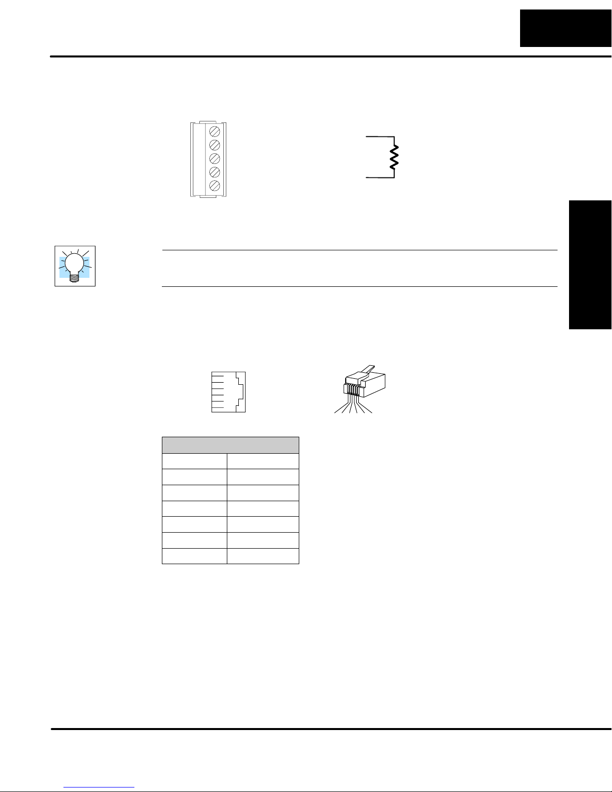
Connect the DeviceNet cable (Belden 3085A, YR–29832 or equivalent) to the
removable connector as shown below. The wire colors are also labeled on the
Controller front. Be sure to connect a terminating resistor (121 Ohm 1%, 1/4W).
V– (black)
CAN* Low (blue)
Shield (bare)
CAN* High (white)
V+ (red)
Connect a terminating
resistor across the CAN
High (white) and CAN
Low (blue) screw
terminals.
The terminating resistor is
* Controller Area Network (CAN)
121 Ohm 1%, 1/4 Watt. (2
resistors are included with
each T1K–DEVNETS).
Tip: Be sure that each end of the DeviceNet network ’trunk” has a proper terminating
resistor connected as shown above.
The T1K–DEVNETS serial port is used to update the firmware of the base controller
when necessary. Use cable part number D2–DSCBL to connect the
T1K–DEVNETS to a PC, or use the following information to make a cable.
Installing the DeviceNet
Base Controller
34 5621
Serial Port Pinout
Pin Signal
1 0V
2 +5V
3 RXD
4 TXD
5 RTS
6 CTS
1 2 3 4 5 6
Safety Guidelines
Installation and
Page 21

2–8
Installing the T1K–DEVNETS Base Controller
Configuring the Controller
Configuring the
DeviceNet Base
Controller
Base Controller
Installing the DeviceNet
Use the software of your DeviceNet master to configure the controller for your
network. Refer to the software Help file and/or manual for help with configuration.
Follow these basic steps when configuring your T1K–DEVNETS controller.
1. Set the Controller Node Address:
In the DeviceNet master software, make sure the Controller node address
is set to an available node number on the DeviceNet network (from 0 to 63).
2. Add the EDS file (if required by the software):
In your DeviceNet software, add the T1K–DEVNETS Electronic Data
Sheet (EDS) file from the disk which came with this manual or from our web
site www.automationdirect.com. Some software may not provide for the
use of EDS files.
3. Commission the Node:
Use the DeviceNet software to “Commission the Node” of your Controller.
Again, some software may not require this.
4. Add the T1K–DEVNETS to the Scan List:
Add the T1K–DEVNETS to the Scan List in your DeviceNet Master
software.
5. Set the Input/Output Bytes:
If required by your DeviceNet software, set the I/O Parameters to Tx =
Output bytes and Rx = Input bytes (on the Scanner’s Scan List tab), for
Polled I/O. Either use the tables located in the appendixes or go to page
E–18 and follow the steps in the example.
6. Map the I/O to the Master:
Map the T1K–DEVNETS I/O to the Scanner using Auto Map, or map the I/O
to another location if desired.
7. Scan:
Go Online (or Scan) to verify the configuration and check for errors.
8. View Indicators on the Controller:
Refer to the Status Indicators when connecting to the network.
Installation and
Safety Guidelines
Page 22

Installing the T1K–DEVNETS Base Controller
2–9
Status Indicators
The Controller has two Status
Indicators, one for Module Status and
the other for Network Status.
MS (Module Status) Indicator
Indication Status
OFF No power to Controller. Check wiring.
ON (Green) Power applied to Controller, no fault
ON (Red) Critical Controller Fault
NS (Network Status) Indicator
Indication Status
OFF No power to Controller or no Network Access
Flashing Green Online but not connected
Solid Green Online, link okay and connected
Flashing Red Recoverable fault
Solid Red Critical Controller Fault (Duplicate ID or Bus off)
Installing the DeviceNet
Base Controller
Outputs Switch
The Outputs switch enables or
disables outputs connected to the
Controller.
Note: It is good safe practice to disable outputs before Hot Swapping modules if the
application allows this.
Safety Guidelines
Installation and
Page 23

2–10
Master/Slave Communications
Installing the T1K–DEVNETS Base Controller
The T1K–DEVNETS controller (slave) communicates with the DeviceNet scanner
(master) by sending Input Data and receiving Output Data. The controller reads
Inputs from I/O Modules and writes Outputs to I/O Modules.
T1K–DEVNETS
To Master
Input Data
Network
Read
(Read Data)
Backplane
Read Inputs
I/O Modules
Base Controller
Installing the DeviceNet
Installation and
Safety Guidelines
From Master
Network
Write
Output Data
(Write Data)
Write Outputs
Page 24

Installing the T1K–DEVNETS Base Controller
Terminator I/O Backplane Communications
The Controller communicates with its I/O modules over the backplane. The I/O is
mapped in consecutive order as shown.
2–11
Network
Read
Network
Write
T1K–DEVNETS
Input Data
Slot 1 Input Data
Slot 2 Input Data
Slot N Input Data
Output Data
Slot 1 Output Data
Slot 2 Output Data
Slot N Output Data
Read
Write
I/O Module, Slot 1 I/O Module, Slot N
Installing the DeviceNet
Inputs Inputs
Base Controller
Outputs Outputs
I/O Module
Memory Map
Refer to the Terminator I/O Installation and I/O Manual (T1K–INST–M) for the
memory map for individual Discrete and/or Analog I/O Modules.
Safety Guidelines
Installation and
Page 25

Specifications
In This Appendix. . . .
Ċ Specifications
1
A
Page 26

A–2
Appendix A
Specifications
Specifications
Specifications
General
Operating Temperature 32° F to 131° F (0° C to 55° C)
Storage Temperature –4° F to 158° F (–20° C to 70° C)
Ambient Humidity 5% – 95% relative humidity (non–condensing)
Voltage Withstand 1500VAC, 1 minute (DeviceNet connector internal)
Insulation Resistance 500VDC, 10MΩ (DeviceNet connector internal)
Vibration Resistance MIL STD 810C, Method 514.2
Shock Resistance MIL STD 810C, Method 516.2
Noise Immunity NEMA (ICS3–304) Impulse noise 1µs, 1000V
FCC class A RFI (145MHz, 435MHz 10W, 10cm)
Atmosphere No corrosive gases
Environmental Pollution Level 2
Size 189”Wx315”Hx326”D (48Wx80Hx83D)
Weight 6.0 oz (170 g)
Appendix C
Error Codes
Communication
Communication form DeviceNet Communication Protocol (Slave)
Predefined Master/Slave
Group 2 Server only
Network Node Address 0 to 63 (Rotary switch setting)
Data Packet 0 to 8 Bytes (Data beyond eight bytes are divided.)
Communication Rate
(Max. cable length)
Communication Status Indicator MS: Module Status LED [Red/Green]
DeviceNet Power Consumption 11 to 25 VDC (45mA max.)
Device Type Generic
Explicit Peer to Peer Message No
I/O Peer to Peer Message No
Configuration Consistency No
Fault Node Recovery No
Communication Baud Rate 125K,
250K, 500K
Master/Scanner No
I/O Slave Bit Strobe
Message Polling
Cyclic
Change of State
125KB (1640 ft./ 500m)
250KB (820 ft./ 250m)
500KB (328 ft./ 100m)
NS: Network Status LED [Red/Green]
DeviceNet
Yes
No
Yes
No
No
Page 27

Specifications
A–3
Serial Port Communications
Connector 6 pin female modular (RJ12 phone jack)
Connection Port Type RS–232C
Protocol Auto detection
K–Sequence (Slave)
Station Number 1 (fixed)
Baud Rate 9600 bps or 19.2 kbps
Dip–Switch 6 (DIP SW6) Setting
Data Bits 8
Start Bits 1
Stop Bits 1
Parity ODD
Communication Time out Prescribed Time
I/O Modules
Number of I/O points Inputs: 1024 Points
Outputs: 1024 Points
Number of Slots (I/O Modules) 1 to 16 slots
Self-diagnostics Watch-dog Timer
Memory check
I/O module types Discrete Input Module
Discrete Output Module
Analog Input Module
Analog Output Module
Install Module Hot swappable
(install / remove modules under power)
Internal Power Consumption 190mA at 5VDC
Max. time of external power loss 10ms
Specifications
Appendix A
Error Codes
Appendix C
Page 28

Tables
In This Appendix. . . .
Ċ DeviceNet Tables
1
B
Page 29

B–2
Data Input and Output Tables
Input Register Object Class (107)
Tables
Appendix B
Tables
Instance = 1 Attribute = 3
Name Data Address Service
Input Register
Vn+00 +00
Vn+01 +02
Vn+02 +04
Vn+03 +06
Vn+04 +08
: :
Vn+62 +124
Vn+63 + 126
Get
The Data Register equals one Word (16 bits).
A maximum of 64 V–memory words can be accessed.
Input Register
Register Input (V–memory) Image Table Mapping
Read
I/O Image
Input Size
2 to 128 bytes
Inputs Data Vn+00
Inputs Data Vn+01
Inputs Data Vn+02
Inputs Data Vn+03
Inputs Data Vn+04
Low Byte
High Byte
Low Byte
High Byte
Low Byte
High Byte
Low Byte
High Byte
Low Byte
High Byte
Inputs Data Vn+61
Inputs Data Vn+62
Inputs Data Vn+63
Low Byte
High Byte
Low Byte
High Byte
Low Byte
High Byte
Page 30

Bit 07 06 05 04 03 02 01 00 Size
Vn + 00 V memory Low byte data Read Byte 1
Vn + 00 V memory High byte data Read Byte 2
Vn + 01 V memory Low byte data Read Byte 3
Vn + 01 V memory High byte data Read Byte 4
Vn + 02 V memory Low byte data Read Byte 5
Vn + 02 V memory High byte data Read Byte 6
: :
: :
Vn + 60 V memory Low byte data Read Byte 121
Vn + 60 V memory High byte data Read Byte 122
Vn + 61 V memory Low byte data Read Byte 123
Vn + 61 V memory High byte data Read Byte 124
Vn + 62 V memory Low byte data Read Byte 125
Vn + 62 V memory High byte data Read Byte 126
Vn + 63 V memory Low byte data Read Byte 127
Vn + 63 V memory High byte data Read Byte 128
B–3
Tables
Appendix B
Tables
Page 31

B–4
Output Register Object Class (108)
Tables
Appendix B
Tables
Instance = 1 Attribute = 3
Name Data Address Service
Output Register
Vn+00 +00
Vn+01 +02
Vn+02 +04
Vn+03 +06
Vn+04 +08
: :
Vn+62 +124
Vn+63 + 126
The Data Register equals one Word (16 bits).
A maximum of 64 V–memory words can be accessed.
Set
Output Register
I/O Image
Write
Register Output (V–memory) Image Table Mapping
Outputs Data Vn+00
Outputs Data Vn+01
Outputs Data Vn+02
Outputs Data Vn+03
Input Size
Outputs Data Vn+04
2 to 128 bytes
Outputs Data Vn+61
Outputs Data Vn+62
Outputs Data Vn+63
Low Byte
High Byte
Low Byte
High Byte
Low Byte
High Byte
Low Byte
High Byte
Low Byte
High Byte
Low Byte
High Byte
Low Byte
High Byte
Low Byte
High Byte
Page 32

Bit 07 06 05 04 03 02 01 00 Size
Vn + 00 V memory Low byte data Write Byte 1
Vn + 00 V memory High byte data Write Byte 2
Vn + 01 V memory Low byte data Write Byte 3
Vn + 01 V memory High byte data Write Byte 4
Vn + 02 V memory Low byte data Write Byte 5
Vn + 02 V memory High byte data Write Byte 6
: :
: :
Vn + 60 V memory Low byte data Write Byte 121
Vn + 60 V memory High byte data Write Byte 122
Vn + 61 V memory Low byte data Write Byte 123
Vn + 61 V memory High byte data Write Byte 124
Vn + 62 V memory Low byte data Write Byte 125
Vn + 62 V memory High byte data Write Byte 126
Vn + 63 V memory Low byte data Write Byte 127
Vn + 63 V memory High byte data Write Byte 128
B–5
Tables
Appendix B
Tables
Data Register Range
RJ12 serial port supports the following registers.
No. Register Number Comment Description
1 V40400–V40477 Input Register Read/Write
2 V40500–V40577 Output Register Read/Write
3 V00000–V02777 Data Register Read/Write
4 V03000–V03077 Explicit Get Command Area Read/Write
5 V03100–V03177 Explicit Set Command Area Read/Write
6 V03200–V07377 Data Register Read/Write
7 V07640–V07613 Special Register Resave
8 V07614–V07617 Parameter Register Read
9 V07620–V07777 Special Register Resave
Note: Not all registers back up data.
Page 33

B–6
I/O Diagnostic Information
Tables
DIP Switch SW4
Tables
Appendix B
The position of DIP Switch SW4 determines whether or not you receive Terminator
I/O diagnostic information. If SW4 is in the OFF (default) position, you will receive
this diagnostic information and you must allow for two additional bytes on the input
(RX) and two additional bytes on the output (TX) for Terminator I/O diagnostic
functions.
If SW4 is placed in the ON position, you will not receive this diagnostic information
and there is no need to allow for the additional bytes.
Following is a description of the diagnostic codes.
Diagnostic (polling) information whenT1K–DEVNETS (slave) transmits to a master.
Address Bytes Data Comment
+0 1 I/O Status Bit 0: Missing module error
ON: Error / OFF: Normal
Bit 1: New module present error
ON: Error / OFF: Normal
Bit 2: I/O diagnostic error
ON: Error / OFF: Normal
Bit 3: Node error (the node number has changed)
ON: Error / OFF: Normal
Bit 4: Idle (Output is idle)
ON: Idle / OFF: Normal
Bit 5: Multiple error (Two or more errors occurred)
ON: Multiple / OFF: Normal
Bit 7: Output status
ON: Enable / OFF: Disable
+1 1 Error Slot 01h: Slot 1
02h: Slot 2
1Fh: Slot 31
21h: Slot 1
22h: Slot 2
.
.
3Fh: Slot 31
The slot number in which the error has occurred.
When the same error occurs by multiple slots,
priority is given to low slot number.
Priority is given to 24V Error or Fuse Error when
multiple errors occur at the same time.
+2
.
+nn
n Bit Data T1K–DEVNETS input module data.
.
.
Module Missing error or New
Module Error
24V Error or Fuse Error
Page 34

B–7
Tables
Diagnostic (polling) information when a master transmits to a T1K–DEVNETS
(slave). The command to select I/O configuration is transferred from peripheral and
written here. When the I/O configuration error occurs the command is executed.
Address Bytes Data Comment
System
Information Object
Specifications
+0 1 Code of except
the following
5Ah Select I/O reconfiguration
C3h Select Output Enable
3Ch Select Output Disable
+1 1 Reserved Not used
+2
.
+nn
n Bit data T1K–DEVNETS output module data.
No request
DeviceNet object that T1K–DEVNETS supports are:
Item Instance Class Number
Special Object System Informa-
tion Object
1–4 106
Appendix B
Tables
Page 35

Image Table Mapping
In This Appendix. . . .
Ċ Image Table Mapping
1
C
Page 36

C–2
Image Table Mapping
Appendix C
Image Table Mapping
Image Table Mapping
Read, Write and Status Byte References
T1K–DEVNETS can access data bytes.
Discrete Input
Discrete Input Point (X,Y,C,S,T,CT,SP) Image Table Mapping
7 6 5 4 3 2 1 0
17 16 15 14 13 12 11 10
27 26 25 24 23 22 21 20
37 36 35 34 33 32 31 30
47 46 45 44 43 42 41 40
57 56 55 54 53 52 51 50
67 66 65 64 63 62 61 60
77 76 75 74 73 72 71 70
Read
I/O Image
Input Size
1 to 8 bytes
Inputs
Inputs
Inputs
Inputs
Inputs
Inputs
Inputs
Inputs
Inputs
Dec. Bit 07 06 05 04 03 02 01 00
Oct. Bit 07 06 05 04 03 02 01 00
7 6 5 4 3 2 1 0 Read Byte 1
17 16 15 14 13 12 11 10 Read Byte 2
27 26 25 24 23 22 21 20 Read Byte 3
37 36 35 34 33 32 31 30 Read Byte 4
47 46 45 44 43 42 41 40 Read Byte 5
57 56 55 54 53 52 51 50 Read Byte 6
67 66 65 64 63 62 61 60 Read Byte 7
77 76 75 74 73 72 71 70 Read Byte 8
Not Supported Write Byte 1
Size
Page 37

Write
Image Table Mapping
Discrete Output Point (X,Y,C,S,T,CT,SP) Image Table Mapping
Inputs
Outputs
I/O Image
Output Size
1 to 8 bytes
7 6 5 4 3 2 1 0
Outputs
17 16 15 14 13 12 11 10
Outputs
27 26 25 24 23 22 21 20
Outputs
37 36 35 34 33 32 31 30
Outputs
47 46 45 44 43 42 41 40
Outputs
57 56 55 54 53 52 51 50
Outputs
67 66 65 64 63 62 61 60
Outputs
77 76 75 74 73 72 71 70
C–3
Image Table Mapping
Dec. Bit 07 06 05 04 03 02 01 00 Size
Oct. Bit 07 06 05 04 03 02 01 00 Size
Not Supported Read Byte 1
7 6 5 4 3 2 1 0 Write Byte 1
17 16 15 14 13 12 11 10 Write Byte 2
27 26 25 24 23 22 21 20 Write Byte 3
37 36 35 34 33 32 31 30 Write Byte 4
47 46 45 44 43 42 41 40 Write Byte 5
57 56 55 54 53 52 51 50 Write Byte 6
67 66 65 64 63 62 61 60 Write Byte 7
77 76 75 74 73 72 71 70 Write Byte 8
Appendix C
Page 38

C–4
Image Table Mapping
Register Input (V–memory) Image Table Mapping
Read
I/O Image
Input Size
2 to 128 bytes
Inputs Data Vn+00
Inputs Data Vn+01
Inputs Data Vn+02
Inputs Data Vn+03
Inputs Data Vn+04
Inputs Data Vn+61
Inputs Data Vn+62
Inputs Data Vn+63
Low Byte
High Byte
Low Byte
High Byte
Low Byte
High Byte
Low Byte
High Byte
Low Byte
High Byte
Low Byte
High Byte
Low Byte
High Byte
Low Byte
High Byte
Appendix C
Image Table Mapping
Bit 07 06 05 04 03 02 01 00 Size
Vn + 00 V memory Low byte data Read Byte 1
Vn + 00 V memory High byte data Read Byte 2
Vn + 01 V memory Low byte data Read Byte 3
Vn + 01 V memory High byte data Read Byte 4
Vn + 02 V memory Low byte data Read Byte 5
Vn + 02 V memory High byte data Read Byte 6
Vn + 03 V memory Low byte data Read Byte 7
Vn + 03 V memory High byte data Read Byte 8
Vn + 04 V memory Low byte data Read Byte 9
Vn + 04 V memory High byte data Read Byte 10
Vn + 05 V memory Low byte data Read Byte 11
Vn + 05 V memory High byte data Read Byte 12
Vn + 06 V memory Low byte data Read Byte 13
Vn + 06 V memory High byte data Read Byte 14
Vn + 07 V memory Low byte data Read Byte 15
Vn + 07 V memory High byte data Read Byte 16
Page 39

Image Table Mapping
Vn + 08 V memory Low byte data Read Byte 17
Vn + 08 V memory High byte data Read Byte 18
Vn + 09 V memory Low byte data Read Byte 19
Vn + 09 V memory High byte data Read Byte 20
: :
: :
: :
: :
Vn + 30 V memory Low byte data Read Byte 61
Vn + 30 V memory High byte data Read Byte 62
Vn + 31 V memory Low byte data Read Byte 63
Vn + 31 V memory High byte data Read Byte 64
: :
: :
C–5
: :
: :
Vn + 60 V memory Low byte data Read Byte 121
Vn + 60 V memory High byte data Read Byte 122
Vn + 61 V memory Low byte data Read Byte 123
Vn + 61 V memory High byte data Read Byte 124
Vn + 62 V memory Low byte data Read Byte 125
Vn + 62 V memory High byte data Read Byte 126
Vn + 63 V memory Low byte data Read Byte 127
Vn + 63 V memory High byte data Read Byte 128
Not Supported Write Byte 1
Image Table Mapping
Appendix C
Page 40

C–6
Image Table Mapping
Register Output (V–memory) Image Table Mapping
Write
I/O Image
Input Size
2 to 128 bytes
Outputs Data Vn+00
Outputs Data Vn+01
Outputs Data Vn+02
Outputs Data Vn+03
Outputs Data Vn+04
Outputs Data Vn+61
Outputs Data Vn+62
Outputs Data Vn+63
Low Byte
High Byte
Low Byte
High Byte
Low Byte
High Byte
Low Byte
High Byte
Low Byte
High Byte
Low Byte
High Byte
Low Byte
High Byte
Low Byte
High Byte
Appendix C
Image Table Mapping
Bit 07 06 05 04 03 02 01 00 Size
Not Supported Read Byte 1
Vn + 00 V memory Low byte data Write Byte 1
Vn + 00 V memory High byte data Write Byte 2
Vn + 01 V memory Low byte data Write Byte 3
Vn + 01 V memory High byte data Write Byte 4
Vn + 02 V memory Low byte data Write Byte 5
Vn + 02 V memory High byte data Write Byte 6
Vn + 03 V memory Low byte data Write Byte 7
Vn + 03 V memory High byte data Write Byte 8
Vn + 04 V memory Low byte data Write Byte 9
Vn + 04 V memory High byte data Write Byte 10
Vn + 05 V memory Low byte data Write Byte 11
Vn + 05 V memory High byte data Write Byte 12
Vn + 06 V memory Low byte data Write Byte 13
Vn + 06 V memory High byte data Write Byte 14
Vn + 07 V memory Low byte data Write Byte 15
Vn + 07 V memory High byte data Write Byte 16
Page 41

Image Table Mapping
Vn + 08 V memory Low byte data Write Byte 17
Vn + 08 V memory High byte data Write Byte 18
Vn + 09 V memory Low byte data Write Byte 19
Vn + 09 V memory High byte data Write Byte 20
: :
: :
: :
: :
Vn + 30 V memory Low byte data Write Byte 61
Vn + 30 V memory High byte data Write Byte 62
Vn + 31 V memory Low byte data Write Byte 63
Vn + 31 V memory High byte data Write Byte 64
: :
: :
: :
: :
C–7
Image Table Mapping
Vn + 60 V memory Low byte data Write Byte 121
Vn + 60 V memory High byte data Write Byte 122
Vn + 61 V memory Low byte data Write Byte 123
Vn + 61 V memory High byte data Write Byte 124
Vn + 62 V memory Low byte data Write Byte 125
Vn + 62 V memory High byte data Write Byte 126
Vn + 63 V memory Low byte data Write Byte 127
Vn + 63 V memory High byte data Write Byte 128
Appendix C
Page 42

C–8
y
+ 0
1
I/O Status
/OFF: N
l
ON: Idle/OFF: Normal
+ 0
1
Image Table Mapping
PLC Mode Image Table Mapping
I/O Image
Input Size
Read
Output Size
Write
2 byte
2 byte
Inputs
00:RUN Mode
03:STOP Mode
Outputs
01:RUN Request
02:STOP Request
Appendix C
Image Table Mapping
Polling format that the T1K–DEVNETS (slave) transmits to a master.
Dec. Bit 07
Oct. Bit 07
RUN
Mode
STOP
Mode
RUN
Request
STOP
Request
06 05 04 03 02 01 00 Size
06 05 04 03 02 01 00
0 0 0 0 0 0 0 0
0 0 0 0 0 0 1 1
0 0 0 0 0 0 0 1
0 0 0 0 0 0 1 0
Read Byte 2
Write Byte 2
Adapter Input/Output Status Word
Address Bytes Data Comment
Bit 0: Not used
Bit 1: Not used
Bit 2: Not used
+ 0 1 I/O Status
+ 1 1 PLC Mode
Bit 3: Node Error (Node number has changed)
ON: Error
Bit 4: IDLE (Output is IDLE)
ON: Idle/OFF: Normal
Bit 7: OUTPUT Status
ON: Disable/OFF: Enable
00h: Mode = STOP
03h: Mode = RUN
orma
Polling format that a master transmits to a DO–DEVNETS (slave).
Address Bytes Data Comment
+ 1 1
No Code No request
C3h Enable OUTPUT
3Ch Disable OUTPUT
01h: RUN request
PLC Mode
02h: STOP request
Page 43

T1K–DEVNETS Think
& Do Setup
In This Appendix. . . .
Ċ T1K-DEVNETS T & D Setup
1
D
Page 44

D–2
T1K–DEVNETS Think & Do Setup
Think & Do Setup
For those who are using the T1K–DEVNETS as a slave with Think & Do Studio, the
following example shows how to setup Think & Do on your network.
T & D Studio setup
for PC control
Use the following procedure to setup the T1K–DEVNETS adapter with Think & Do
Studio. Be sure that the Node Address switches have been set to a proper address.
1. Click on Add Driver and SST card is installed.
2. Set MAC ID to 62.
3. Set baud rate (500K, SW1–1 OFF, –2 ON, in this example).
4. Set scanner interval to 0.
5. Set timeout shutdown to 5.
6. EDS not needed.
Appendix D
Think & Do Setup
Page 45

Think & Do Setup
D–3
7. Click on connection.
Think & Do will display T1K–DEVNETS MacID–2.
Inputs and outputs are displayed.
Error Codes
Appendix C
8. Click on Scan and communication will begin.
Think & Do Setup
Appendix D
Page 46

T1K–DEVNETS and
RSNetWorxt Setup
In this Appendix. . . .
Ċ Setup T1K-DEVNETS with RSNetWorxt
1
E
Page 47

E–2
RSNetWorxt Setup
Setup T1K–DEVNETS with RSNetWorxt
For those who are using the T1K–DEVNETS as a slave with an Allen–Bradley PLC,
the examples on the following pages have worked for us, and will be a guide for you.
These steps should help you through the process of setting up your Allen–Bradley
DeviceNet network using RSNetWorxt. If you encounter any difficulties with the
setup process, please contact your local Rockwell International representative.
RSLinx
Appendix C
Error Codes
Begin by opening your RSLinx to configure the DeviceNet driver.
1. Click on Communications.
2. Click on Configure
Drivers.
3. Click on the down
arrowhead, , and
select a driver from the
drop–down list.
4. Click Add New.
A DF1 driver is selected in this
example.
Appendix E
RSNetWorx Setup
Note: Selecting a new driver may prompt you to reboot or to restart your computer.
Page 48

5. Click OK in the pop–up
window.
This window will appear.
6. Click on Auto–Configure
to setup the communication
parameters.
E–3
RSNetWorxt Setup
Auto Configuration Successfull
will appear.
7. Click OK.
Error Codes
Appendix C
RSNetWorx Setup
Appendix E
Page 49

E–4
RSNetWorxt Setup
The Configure Drivers window
will now appear showing the
Status as Running.
The next step is to add a
DeviceNet driver.
8. Click on the down
arrowhead, , and select
your choice of drivers from
the drop–down list.
9. Click on Add New.
Appendix C
Error Codes
Appendix E
RSNetWorx Setup
This window will appear.
10. Select the proper driver,
then click Select.
Page 50

The DeviceNet Interface
Configuration window will
appear briefly.
This window will appear for
you to setup the pass
through port.
Be sure that you select the
proper slot where the
scanner module is located.
E–5
RSNetWorxt Setup
If this does not match, you
will need to reconfigure the
I/O in RSLogix.
11. Type in a name for the
driver, then click OK.
This window will appear
indicating that both drivers
are Running.
Error Codes
Appendix C
RSNetWorx Setup
Appendix E
Page 51

E–6
RSNetWorxt Setup
RSLogix
You are ready to connect to the PLC using your RSLogix software.
1. Click on Communications
and select Who Active Go
Online.
2. When this window appears,
select the PLC to connect
to.
3. Click OK.
Appendix C
Error Codes
Appendix E
RSNetWorx Setup
This window will appear with
the relay ladder program.
You now want to configure
the I/O. This must be done
OFFLINE in order to change
the configuration.
4. Select I/O Configuration.
Page 52

The I/O Configuration window
will come into view. When you
select the scanner module,
verify that it is in the correct
slot.
5. Click Adv Config.
The Advanced I/O
Configuration window will
appear. The M0 and M1
Lengths will show the default
of 256. Change this to 361.
6. Click OK.
E–7
RSNetWorxt Setup
Error Codes
Appendix C
RSNetWorx Setup
Appendix E
Page 53

E–8
RSNetWorxt Setup
Configure
T1K–DEVNETS
with RSNetWorx
Using the EDS file
You are now ready to configure the T1K–DEVNETS. First, open RSNetWorx. Look
for Koyo Electronics in the hardware tree listed under Vendor. Click on the + to show
the devices for Koyo. The following example shows two devices, D0–DEVNETS and
T1K–DEVNETS.
RSNetWorx opened.
If you do not see your device listed, it will need to be added from the EDS file (refer to
page 2–8). The following example will guide you through the procedure of installing
the device from the EDS file.
Appendix C
Error Codes
Appendix E
RSNetWorx Setup
Click Tools and select EDS
Wizard....
Page 54

The EDS Wizard will open.
Simply follow the instructions
to register the device.
Register the EDS file.
E–9
RSNetWorxt Setup
Enter the path for the EDS file.
Error Codes
Appendix C
RSNetWorx Setup
Appendix E
Page 55

E–10
RSNetWorxt Setup
EDS file installation results.
You can change the icon
image for your device in this
window.
Appendix C
Error Codes
Appendix E
RSNetWorx Setup
Review what you have done.
Page 56

EDS Wizard complete.
E–11
RSNetWorxt Setup
Go on line
You will want to go on line with the network now.
In the main RSNetWorx
window,
1. Click on Network to select
Online.
2. Select your network from
the pop–up window.
3. Click OK.
Error Codes
Appendix C
RSNetWorx Setup
Appendix E
Page 57

E–12
RSNetWorxt Setup
This message will appear.
4. Click OK.
Browsing network message.
Once the nodes are found,
each node icon will appear on
the RSNetWorx window.
After all of the nodes have
been found, browse can be
cancelled.
Appendix C
Error Codes
Set up I/O
parameters
Appendix E
RSNetWorx Setup
Now you can set up the I/O paramerters for the devices. The scanner needs to be
configured first. This is done by accessing the scanner properties.
1. Selecting the scanner
module can be done in two
different ways. Either click
on the scanner name and
right click the mouse or
click on Device then click
on Properties in the
pop–up window.
Page 58

The properties window will
appear.
2. Click Module.
3. Click Upload.
E–13
RSNetWorxt Setup
Uploading network information.
Note: Do not cancel. The entire network data must be allowed to upload.
The data appears.
4. Select the correct slot
number which the DeviceNet
scanner module is residing.
5. Click Scanlist.
Error Codes
Appendix C
RSNetWorx Setup
Appendix E
Page 59

E–14
RSNetWorxt Setup
If the node that you want is not
in the Scanlist, it needs to be
moved to the list.
6. Highlight T1K–DEVNETS
7. Click the right arrow.
Now that T1K–DEVNETS is in
the list, be sure that it is
selected.
8. Click Edit I/O
Parameters.
Appendix C
Error Codes
Appendix E
RSNetWorx Setup
9. Set the Rx Size and the Tx
Size to match the polled
data size for the number
of I/O bytes (refer to
tables in Appendix C).
10. Click OK.
Refer to page E–18 (Set
Class Instance Attribute)
if the total number of Rx
and Tx bytes are not
known.
Page 60

This window will appear.
11. Click Yes.
E–15
RSNetWorxt Setup
Map the nodes
Map each node.
1. Click the Input tab in the
properties window.
Be sure that T1K–DEVNETS is
selected.
2. Select Discrete for Memory,
and 0 for Start Word.
3. Click AutoMap.
NOTE: M file is used with
explicit messaging.
At the completion of the input
AutoMapping, the window will
look like this example. The
T1K–DEVNETS node is now
shown.
Error Codes
Appendix C
RSNetWorx Setup
Appendix E
Page 61

E–16
RSNetWorxt Setup
Now, map the outputs just the
way you mapped the inputs.
This time:
1. Click the Output tab in the
properties window.
Be sure that T1K–DEVNETS is
selected.
2. Select Discrete for Memory,
and 0 for Start Word.
3. Click AutoMap.
Appendix C
Error Codes
At the completion of the output
AutoMapping, the window will
appear like this example. The
T1K–DEVNETS node is now
shown.
Appendix E
RSNetWorx Setup
Page 62

E–17
RSNetWorxt Setup
Download the scanlist to the
scanner.
1. Select the Scanlist tab in
the properties window.
2. Select Download to
Scanner.
In the pop–up window:
3. Check All Records, then
4. Click Download.
Note: Verify that the processor is in program mode before downloading the scanlist.
This is an error message that
may appear.
When the download indication
ends, download is complete.
Error Codes
Appendix C
RSNetWorx Setup
Appendix E
Page 63

E–18
RSNetWorxt Setup
Set Class Instance
Attribute
Appendix C
Error Codes
Use the Service Class Instance Attribute Editor to set the I/O to read and write to the
T1K –DEVNETS.
1. Select the T1K–DEVNETS
node. Either click on
Device
or right click on the node
symbol in theRSNetWorx
window.
2. Select Class Instance
Editor in the pop–up
window.
3. Setup input attributes in this
window.
Object Address must be set
to: Class = 5, Instance = 2,
Attribute = 7
Size = Word (2 bytes).
Appendix E
RSNetWorx Setup
4. Click on Execute.
Read the data here.
Page 64

5. Setup output attributes in
this window.
Object Address must be set
to:
Class = 5, Instance = 2,
Attribute = 8
Size = Word (2 bytes).
6. Click on Execute.
Read the data here.
E–19
RSNetWorxt Setup
Error Codes
Appendix C
RSNetWorx Setup
Appendix E
 Loading...