

Page 1

Do-more T1H Series PLC Hardware User Manual
Manual Number: T1H-DM-M
Page 2

~
WARNING ~
Thank you for purchasing automation equipment from Automationdirect.com®, doing business as,
AutomationDirect. We want your new automation equipment to operate safely. Anyone who installs or
uses this equipment should read this publication (and any other relevant publications) before installing or
operating the equipment.
To minimize the risk of potential safety problems, you should follow all applicable local and national
codes that regulate the installation and operation of your equipment. These codes vary from area to area
and usually change with time. It is your responsibility to determine which codes should be followed, and
to verify that the equipment, installation, and operation is in compliance with the latest revision of these
codes.
At a minimum, you should follow all applicable sections of the National Fire Code, National Electrical
Code, and the codes of the National Electrical Manufacturer’s Association (NEMA). There may be local
regulatory or government offices that can also help determine which codes and standards are necessary for
safe installation and operation.
Equipment damage or serious injury to personnel can result from the failure to follow all applicable
codes and standards. We do not guarantee the products described in this publication are suitable for
your particular application, nor do we assume any responsibility for your product design, installation, or
operation.
Our products are not fault-tolerant and are not designed, manufactured or intended for use or resale as
on-line control equipment in hazardous environments requiring fail-safe performance, such as in the
operation of nuclear facilities, aircraft navigation or communication systems, air traffic control, direct life
support machines, or weapons systems, in which the failure of the product could lead directly to death,
personal injury, or severe physical or environmental damage (“High Risk Activities”). AutomationDirect
specifically disclaims any expressed or implied warranty of fitness for High Risk Activities.
For additional warranty and safety information, see the Terms and Conditions section of our catalog.
If you have any questions concerning the installation or operation of this equipment, or if you need
additional information, please call us at 770-844-4200.
This publication is based on information that was available at the time it was printed. At
AutomationDirect we constantly strive to improve our products and services, so we reserve the right to
make changes to the products and/or publications at any time without notice and without any obligation.
This publication may also discuss features that may not be available in certain revisions of the product.
Trademarks
This publication may contain references to products produced and/or offered by other companies. The
product and company names may be trademarked and are the sole property of their respective owners.
AutomationDirect disclaims any proprietary interest in the marks and names of others.
Copyright 2020, Automationdirect.com® Incorporated
No part of this manual shall be copied, reproduced, or transmitted in any way without the prior, written
consent of Automationdirect.com® Incorporated. AutomationDirect retains the exclusive rights to all
information included in this document.
All Rights Reserved
Page 3

~ ADVERTENCIA ~
Gracias por comprar equipo de automatización de Automationdirect.com®. Deseamos que su nuevo equipo
de automatización opere de manera segura. Cualquier persona que instale o use este equipo debe leer esta
publicación (y cualquier otra publicación pertinente) antes de instalar u operar el equipo.
Para reducir al mínimo el riesgo debido a problemas de seguridad, debe seguir todos los códigos de seguridad
locales o nacionales aplicables que regulan la instalación y operación de su equipo. Estos códigos varian de
área en área y usualmente cambian con el tiempo. Es su responsabilidad determinar cuales códigos deben ser
seguidos y verificar que el equipo, instalación y operación estén en cumplimiento con la revisión mas reciente
de estos códigos.
Como mínimo, debe seguir las secciones aplicables del Código Nacional de Incendio, Código Nacional Eléctrico,
y los códigos de (NEMA) la Asociación Nacional de Fabricantes Eléctricos de USA. Puede haber oficinas de
normas locales o del gobierno que pueden ayudar a determinar cuales códigos y normas son necesarios para una
instalación y operación segura.
Si no se siguen todos los códigos y normas aplicables, puede resultar en daños al equipo o lesiones serias a
personas. No garantizamos los productos descritos en esta publicación para ser adecuados para su aplicación
en particular, ni asumimos ninguna responsabilidad por el diseño de su producto, la instalación u operación.
Nuestros productos no son tolerantes a fallas y no han sido diseñados, fabricados o intencionados para uso
o reventa como equipo de control en línea en ambientes peligrosos que requieren una ejecución sin fallas,
tales como operación en instalaciones nucleares, sistemas de navegación aérea, o de comunicación, control de
tráfico aéreo, máquinas de soporte de vida o sistemas de armamentos en las cuales la falla del producto puede
resultar directamente en muerte, heridas personales, o daños físicos o ambientales severos (“Actividades de Alto
Riesgo”). Automationdirect.com específicamente rechaza cualquier garantía ya sea expresada o implicada
para actividades de alto riesgo.
Para información adicional acerca de garantía e información de seguridad, vea la sección de Términos
y Condiciones de nuestro catálogo. Si tiene alguna pregunta sobre instalación u operación de este equipo, o
si necesita información adicional, por favor llámenos al número 770-844-4200 en Estados Unidos.
Esta publicación está basada en la información disponible al momento de impresión. En Automationdirect.
com nos esforzamos constantemente para mejorar nuestros productos y servicios, así que nos reservamos el
derecho de hacer cambios al producto y/o a las publicaciones en cualquier momento sin notificación y sin
ninguna obligación. Esta publicación también puede discutir características que no estén disponibles en ciertas
revisiones del producto.
Marcas Registradas
Esta publicación puede contener referencias a productos producidos y/u ofrecidos por otras compañías. Los nombres de las
compañías y productos pueden tener marcas registradas y son propiedad única de sus respectivos dueños. Automationdirect.com,
renuncia cualquier interés propietario en las marcas y nombres de otros.
PROPIEDAD LITERARIA 2020, AUTOMATIONDIRECT.COM® INCORPORATED
No se permite copiar, reproducir, o transmitir de ninguna forma ninguna parte de este manual sin previo consentimiento por escrito
de Automationdirect.com
este documento. Los usuarios de este equipo pueden copiar este documento solamente para instalar, configurar y mantener el equipo
correspondiente. También las instituciones de enseñanza pueden usar este manual para propósitos educativos.
®
Incorprated. Automationdirect.com retiene los derechos exclusivos a toda la información incluida en
Todos los derechos reservados
Page 4

~ AVERTISSEMENT
Nous vous remercions d’avoir acheté l’équipement d’automatisation de Automationdirect.com®, en faisant des
affaires comme, AutomationDirect. Nous tenons à ce que votre nouvel équipement d’automatisation fonctionne en
toute sécurité. Toute personne qui installe ou utilise cet équipement doit lire la présente publication (et toutes les
autres publications pertinentes) avant de l’installer ou de l’utiliser.
Afin de réduire au minimum le risque d’éventuels problèmes de sécurité, vous devez respecter tous les codes locaux
et nationaux applicables régissant l’installation et le fonctionnement de votre équipement. Ces codes diffèrent d’une
région à l’autre et, habituellement, évoluent au fil du temps. Il vous incombe de déterminer les codes à respecter et
de vous assurer que l’équipement, l’installation et le fonctionnement sont conformes aux exigences de la version la
plus récente de ces codes.
Vous devez, à tout le moins, respecter toutes les sections applicables du Code national de prévention des incendies,
du Code national de l’électricité et des codes de la National Electrical Manufacturer’s Association (NEMA). Des
organismes de réglementation ou des services gouvernementaux locaux peuvent également vous aider à déterminer
les codes ainsi que les normes à respecter pour assurer une installation et un fonctionnement sûrs.
L’omission de respecter la totalité des codes et des normes applicables peut entraîner des dommages à l’équipement
ou causer de graves blessures au personnel. Nous ne garantissons pas que les produits décrits dans cette publication
conviennent à votre application particulière et nous n’assumons aucune responsabilité à l’égard de la conception, de
l’installation ou du fonctionnement de votre produit.
Nos produits ne sont pas insensibles aux défaillances et ne sont ni conçus ni fabriqués pour l’utilisation ou la revente
en tant qu’équipement de commande en ligne dans des environnements dangereux nécessitant une sécurité absolue,
par exemple, l’exploitation d’installations nucléaires, les systèmes de navigation aérienne ou de communication, le
contrôle de la circulation aérienne, les équipements de survie ou les systèmes d’armes, pour lesquels la défaillance du
produit peut provoquer la mort, des blessures corporelles ou de graves dommages matériels ou environnementaux
(«activités à risque élevé»). La société AutomationDirect nie toute garantie expresse ou implicite d’aptitude à
l’emploi en ce qui a trait aux activités à risque élevé.
Pour des renseignements additionnels touchant la garantie et la sécurité, veuillez consulter la section Modalités et
conditions de notre documentation. Si vous avez des questions au sujet de l’installation ou du fonctionnement de cet
équipement, ou encore si vous avez besoin de renseignements supplémentaires, n’hésitez pas à nous téléphoner au
770-844-4200.
Cette publication s’appuie sur l’information qui était disponible au moment de l’impression. À la société
AutomationDirect, nous nous efforçons constamment d’améliorer nos produits et services. C’est pourquoi nous
nous réservons le droit d’apporter des modifications aux produits ou aux publications en tout temps, sans préavis ni
quelque obligation que ce soit. La présente publication peut aussi porter sur des caractéristiques susceptibles de ne
pas être offertes dans certaines versions révisées du produit.
~
Marques de commerce
La présente publication peut contenir des références à des produits fabriqués ou offerts par d’autres entreprises. Les
désignations des produits et des entreprises peuvent être des marques de commerce et appartiennent exclusivement à
leurs propriétaires respectifs. AutomationDirect nie tout intérêt dans les autres marques et désignations.
Copyright 2020, Automationdirect.com® Incorporated
Nulle partie de ce manuel ne doit être copiée, reproduite ou transmise de quelque façon que ce soit sans le
consentement préalable écrit de la société Automationdirect.com® Incorporated. AutomationDirect conserve les
droits exclusifs à l’égard de tous les renseignements contenus dans le présent document.
Tous droits réservés
Page 5

Notes
Page 6
Do-more T1H Series PLC User Manual
Please include the Manual Number and the Manual Issue, both shown below,
when communicating with Technical Support regarding this publication.
Manual Number: T1H-DM-M
Issue: 1st Edition, Rev. C
Issue Date: 08/20
Publication History
Issue Date Description of Changes
1st Edition 10/13 Original
Rev. A 10/16 Added T1F-16TMST thermistor input module
Rev. B 10/18 Updated EU Directives appendix
ev. C 08/20 T1H-PBC obsoleted
R
Page 7

Table of ConTenTs
Chapter 1: Getting Started
Introduction ............................................................................................................ 1–2
Purpose of this Manual .............................................................................................1–2
Purpose of this Chapter ............................................................................................ 1–2
Online Help Files and Other Documentation ............................................................ 1–2
Technical Support ....................................................................................................1–2
Conventions Used ...................................................................................................... 1–3
Key Topics for Each Chapter .....................................................................................1–3
Before You Begin ....................................................................................................... 1–4
Do-more T1H Series PLC System Components ......................................................... 1–5
Do-more Software System Requirements ..................................................................1–6
Step 1: Install Do-more Designer Software .............................................................. 1–7
Step 2: Launch Do-more Designer Software .......................................................... 1–10
Step 3: Install Hardware .......................................................................................... 1–12
Step 4: Apply Power to the PLC ............................................................................1–13
Step 5: Establish Communication ...........................................................................1–14
Step 6: Verify Hardware Configuration ..................................................................1–20
Step 7: Create a Ladder Logic Program ..................................................................1–24
Rung #1 ................................................................................................................. 1-24
Rung #2 ................................................................................................................. 1-27
Step 8: Save a Project .............................................................................................. 1–29
Step 9: Write Project to the Do-more T1H Series PLC .......................................... 1–29
Step 10: Testing Project Using Data View .............................................................. 1–30
Accessing the Help File ............................................................................................ 1–32
Page 8

Table of Contents
Chapter 2: Do-more T1H Series PLC Overview
Do-more T1H Series PLC Overview .......................................................................... 2–2
Module Compatibility ..............................................................................................2–3
Communications ...................................................................................................... 2–4
Chapter 3: Specifications - CPU Modules
CPU Specifications .................................................................................................. 3–2
CPU General Specifications .......................................................................................3–2
Communications Ports Specifications ....................................................................... 3–4
Port 1 Specifications (USB) .......................................................................................3–4
Port 2 Specifications (Serial) .....................................................................................3–4
Port 3 Specifications (Ethernet) ................................................................................3–5
Ethernet I/O ............................................................................................................... 3–6
Status Indicators ........................................................................................................ 3–8
Mode Switch Functions ............................................................................................. 3–8
Dip Switch Specifications ..........................................................................................3–9
Battery Replacement ...............................................................................................3–12
Chapter 4: Specifications - Terminal Bases and Power Supplies
T1K-08B(-1) I/O Terminal Base ................................................................................. 4–2
T1K-16B(-1) I/O Terminal Base ................................................................................. 4–2
T1K-01AC, T1K-01DC Power Supply ......................................................................... 4–4
Calculating the Power Budget ..................................................................................4–6
Chapter 5: Specifications - Discrete I/O Modules
Discrete I/O Module Overview..................................................................................5–2
Discrete I/O Modules ................................................................................................5–3
Chapter 6: Specifications - Analog I/O Modules
Analog I/O Module Overview ...................................................................................6–2
Analog I/O Modules ..................................................................................................6–6
Do-more T1H Series PLC Hardware User Manual, 1st Edition, Rev. C
ii
Page 9

Table of Contents
Chapter 7: Specifications - Specialty Modules
Specialty Module Overview ....................................................................................... 7–2
Specialty Modules ...................................................................................................... 7–2
Chapter 8: Installation and Wiring
Safety Guidelines ....................................................................................................... 8–2
Mounting Guidelines ................................................................................................. 8–5
Assembling the Components .................................................................................... 8–9
Multiple Power Supplies / Local Expansion Configurations ..................................8–11
Wiring Guidelines .................................................................................................... 8–19
I/O Wiring Strategies ..............................................................................................8–24
Appendix A: European Union Directives (CE)
European Union (EU) Directives ............................................................................... A-2
Basic EMC Installation Guidelines ............................................................................. A-5
Do-more T1H Series PLC Hardware User Manual, 1st Edition, Rev. C
iii
Page 10

Table of Contents
Notes:
iv
Do-more T1H Series PLC Hardware User Manual, 1st Edition, Rev. C
Page 11

Chapter
Chapter
Chapter
GettinG Started
1
1
1
In This Chapter:
Introduction ����������������������������������������������������������������������������������������������������������������� 1–2
Purpose of this Manual ����������������������������������������������������������������������������������������������� 1–2
Purpose of this Chapter ���������������������������������������������������������������������������������������������� 1–2
Online Help Files and Other Documentation �������������������������������������������������������������� 1–2
Technical Support������������������������������������������������������������������������������������������������������� 1–2
Conventions Used �������������������������������������������������������������������������������������������������������� 1–3
Key Topics for Each Chapter ��������������������������������������������������������������������������������������� 1–3
Before You Begin ��������������������������������������������������������������������������������������������������������� 1–4
Do-more T1H Series PLC System Components ����������������������������������������������������������� 1–5
Do-more Software System Requirements �������������������������������������������������������������������� 1–6
Step 1: Install Do-more Designer Software ���������������������������������������������������������������� 1–7
Step 2: Launch Do-more Designer Software ������������������������������������������������������������ 1–10
Step 3: Install Hardware �������������������������������������������������������������������������������������������� 1–12
Step 4: Apply Power to the PLC �������������������������������������������������������������������������������� 1–13
Step 5: Establish Communication ����������������������������������������������������������������������������� 1–14
Step 6: Verify Hardware Configuration ��������������������������������������������������������������������1–20
Step 7: Create a Ladder Logic Program �������������������������������������������������������������������� 1–24
Rung #1 ������������������������������������������������������������������������������������������������������������������� 1–24
Rung #2 ������������������������������������������������������������������������������������������������������������������� 1–27
Step 8: Save a Project ������������������������������������������������������������������������������������������������ 1–29
Step 9: Write Project to the Do-more T1H Series PLC �������������������������������������������� 1–29
Step 10: Testing Project Using Data View ���������������������������������������������������������������� 1–30
Accessing the Help File ���������������������������������������������������������������������������������������������� 1–32
Page 12

Chapter 1: Getting Started
Introduction
Purpose of this Manual
Thank you for purchasing from our Do-more PLC family of products. This manual shows
you how to install, set up, program, troubleshoot and maintain your Do-more T1H Series
PLC. For installation personnel, this manual contains information on power and signal
wiring, mounting details and configuration procedures.
This manual can be very helpful as a quick reference guide for those who are experienced in
PLCs. For those who may be new to PLCs or our products, reading this manual will give you
an understanding of the variety of features available with the Do-more PLC.
Purpose of this Chapter
This chapter will guide you through the basic set up of a Do-more T1H Series PLC. It
contains step by step instructions on installing the programming software, installing and
configuring your hardware, applying power to the PLC, establishing a communications link,
and creating, saving and writing a project to the CPU. Once these steps are completed, your
Do-more T1H Series PLC will be running a ladder logic project that you have programmed.
Online Help Files and Other Documentation
Do-more Designer, the Do-more PLC programming software, is available for free download
from our website at:
http://www.automationdirect.com
The software includes searchable online help topics covering all aspects of the software,
instruction set, module set up and communication.
1–2
Technical Support
We strive to make our manuals the best in the industry. We rely on your feedback to let
us know if we are reaching our goal. If you cannot find the solution to your particular
application, or, if for any reason you need technical assistance, please call us at:
770-844-4200
Our technical support group will work with you to answer your questions. They are available
Monday through Friday from 9:00 A.M. to 6:00 P.M. Eastern Time. We also encourage
you to visit our web site where you can find technical and non-technical information about
our products and our company.
http://www.automationdirect.com
Do-more T1H Series PLC Hardware User Manual, 1st Edition, Rev. C
Page 13
Conventions Used
When you see the “note pad” icon in the left-hand margin, the paragraph to its immediate right will be a
special note. Notes represent information that may make your work quicker or more efficient. The word
NOTE: in boldface will mark the beginning of the text.
When you see the “exclamation point” icon in the left-hand margin, the paragraph to its immediate right
will be a warning. This information could prevent injury, loss of property, or even death in extreme
cases. Any warning in this manual should be regarded as critical information that should be read in its
entirety. The word WARNING in boldface will mark the beginning of the text.
Chapter 1: Getting Started
Key Topics for Each Chapter
The beginning of each chapter will list the key topics
that can be found in that chapter.
Do-more T1H Series PLC Hardware User Manual, 1st Edition, Rev. C
Getting Started!
In This Chapter...
.............................................................................1-2
Introduction
About Getting Started!
Supplemental Manuals and Other Help
Technical Support
....................................................................1-2Purpose of this Manual
......................................................................1-2
.............................................................................1-2
....................................................................1-3Conventions Used
CHAPTER
1
............................................1-2
1–3
Page 14
Chapter 1: Getting Started
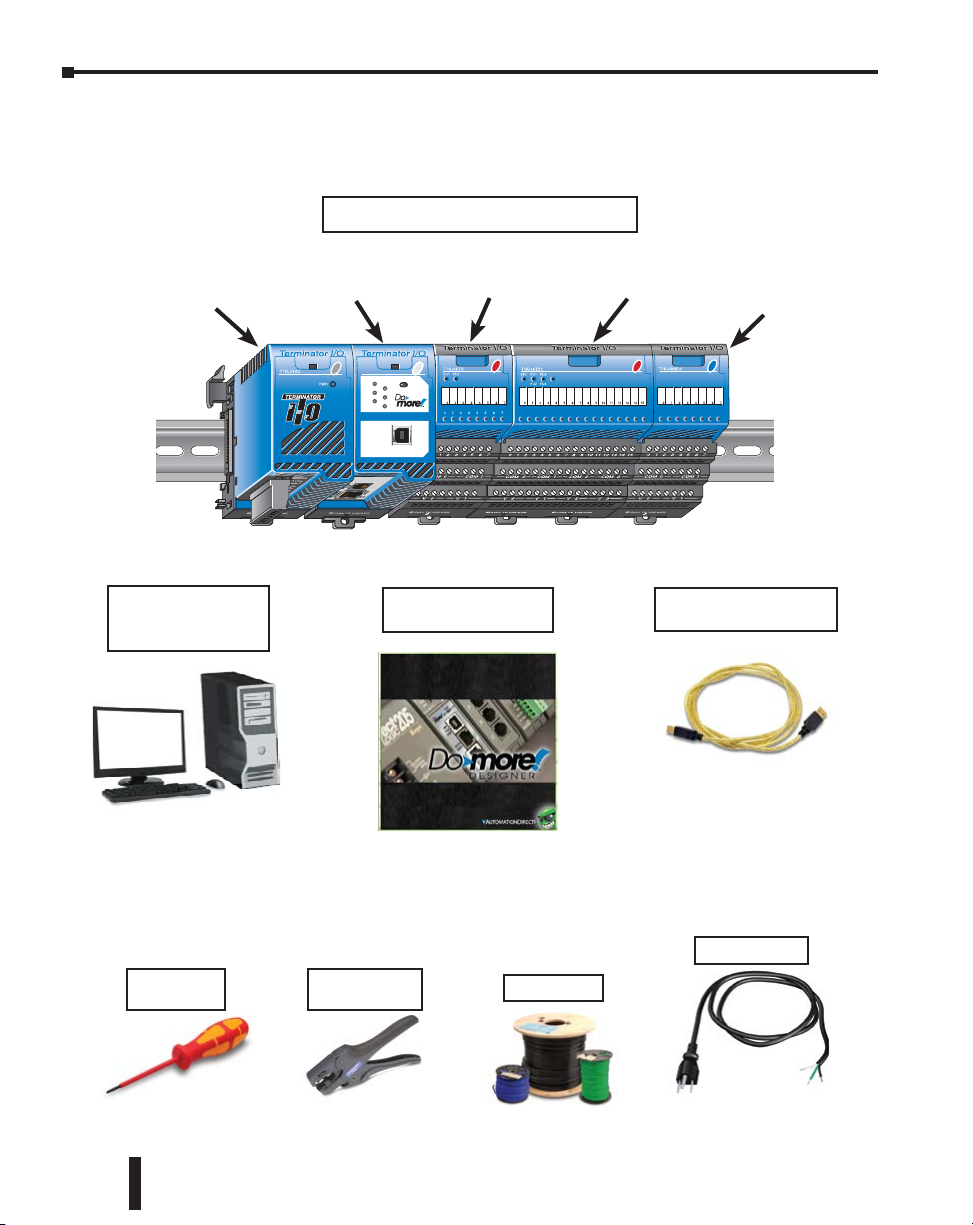
Before You Begin
It is recommended that the following items be available to make this short step-by-step
introduction to the Do-more T1H Series PLC go smoothly.
Example Do-more T1H Series PLC
T1K-01AC
110/220 VAC
Power Supply
PC Running
Windows XP, Vista,
Windows 7, Windows 8
Not available from
Automationdirect.com.
Do-more
T1H-DM1E CPU
Module
T1H-DM1E
RUN
ERR
T1K-08TR Relay
Output Module
TERM
RUN STOP
USB
I/O
TX
RX
USB
PGM
PORT
Do-more Designer
Programming Software
Download software from
our webste at: http://www.
automationdirect.com
T1K-16TD1 Discrete
Output Module
USB-A to USB-B
Programming Cable
You can also use an Ethernet
or Serial (D2-DSCBL) cable
for programming, but we
recommend using a USB cable;
just plug it in and it works.
T1K-08ND3 Discrete
Input Module
1–4
Screwdriver
TW-SD-VSL-1
Wire Strippers
DN-WS
Hookup Wire
Do-more T1H Series PLC Hardware User Manual, 1st Edition, Rev. C
AC Power Cord
Not available from
Automationdirect.com.
Page 15
Chapter 1: Getting Started
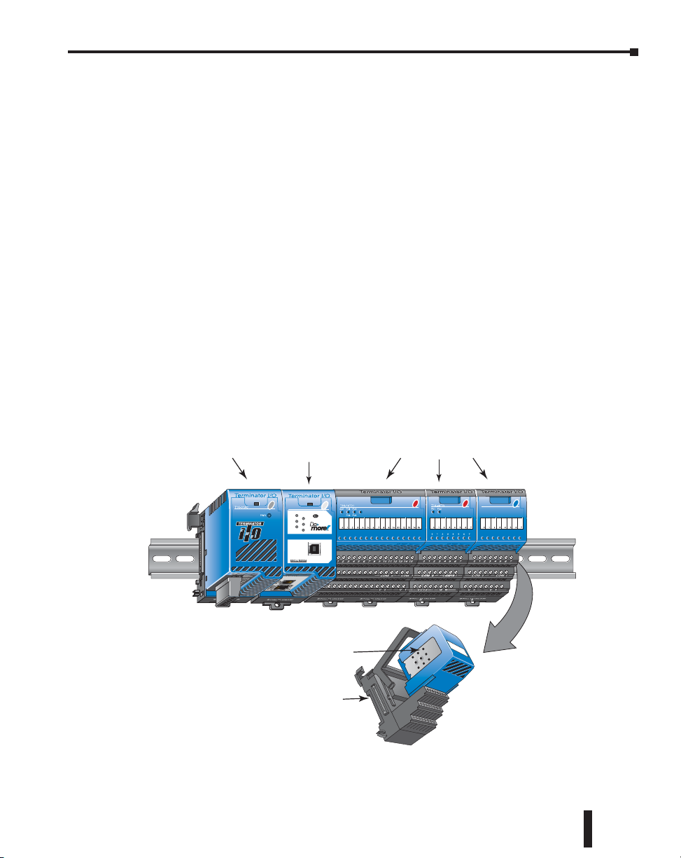
Power Supply
I/O Modules
Do-more T1H Series PLC System Components
The Do-more T1H Series CPU modules were designed for use with the Terminator I/O
product line. For those not familiar with Terminator I/O, it is a modular system which
combines the functions of terminal blocks and I/O modules for distributed I/O. Each
Terminator I/O system contains: a Power Supply, a Base Controller, and one or more
I/O Module(s). Now with the addition of the T1H CPU, standing in place of the Base
Controller, the Terminator distributed I/O system becomes a complete, highly functional,
stand-alone PLC system.
CPU
T1H-DM1/T1H-DM1E
Power Supplies
120/240 VAC and 12/24 VDC power supplies are available. The AC version has a built-in
24 VDC supply. A power supply must be the leftmost component in a slave system followed
by the CPU. Additional power supplies should be added between I/O modules to meet
power budget requirements.
I/O Modules
A Terminator I/O module assembly consists of an I/O module and a separate base, as shown
below. A complete range of discrete modules which support 12/24 VDC, 110/220 VAC and
up to 7A relay outputs is offered. The analog I/O modules provide 12 and 14 bit resolution
and several selections of I/O signal ranges (including bipolar). The temperature input
modules provide 16 bit resolution with several temperature input range selections.
Do-more CPU
T1H-DM1E
TERM
RUN
RUN STOP
USB
I/O
TX
ERR
RX
USB
PGM
PORT
I/O Module
I/O Base
Do-more T1H Series PLC Hardware User Manual, 1st Edition, Rev. C
1–5
Page 16

Chapter 1: Getting Started
Do-more Software System Requirements
The Do-more Designer Windows-based programming software works with Windows® XP
(Home or Professional, 32-bit), Vista (Home, Basic, Premium, 32 or 64-bit), Windows 7
(Home, Professional, Ultimate, 32 or 64-bit) or Windows 8 (Home, Professional, Enterprise
32 or 64-bit; Windows 8 RT edition is NOT supported).
Please check the following requirements when choosing your PC configuration:
• Minimum PC to PLC Connectivity, at least one of the following:
-
USB Port: connects to the CPU with USB-A connector (USB-A to USB-B cable)
- RS-232 Serial Port: connects to the CPU with RJ-12 connector (RJ-12 to DB9 or RJ-12
to USB-B serial converter cable)
- Ethernet Port: connects to the CPU (T1H-DM1E) with RJ-45 10Base-T or 100Base-T
(Cat5 Patch Cable)
• Hard Disk: 100MB free disk space
• Video Display: 1024x768, 256 colors resolution (1280x720, true color recommended)
• Windows XP, 32-bit:
- 800MHz, single core CPU (2GHz, multi-core or hyperthreaded recommended)
- 512MB RAM (2GB recommended)
• Vista, Windows 7 or Windows 8, 32 or 64-bit:
- 1GHz, single core CPU (2GHz, multi-core recommended)
- 1GB RAM (3GB recommended)
1–6
NOTE: The PC/Laptop/Ethernet Switch connector at the “opposite end” of the PLC connector will dictate what
kind of cable you will need.
Do-more T1H Series PLC Hardware User Manual, 1st Edition, Rev. C
Page 17
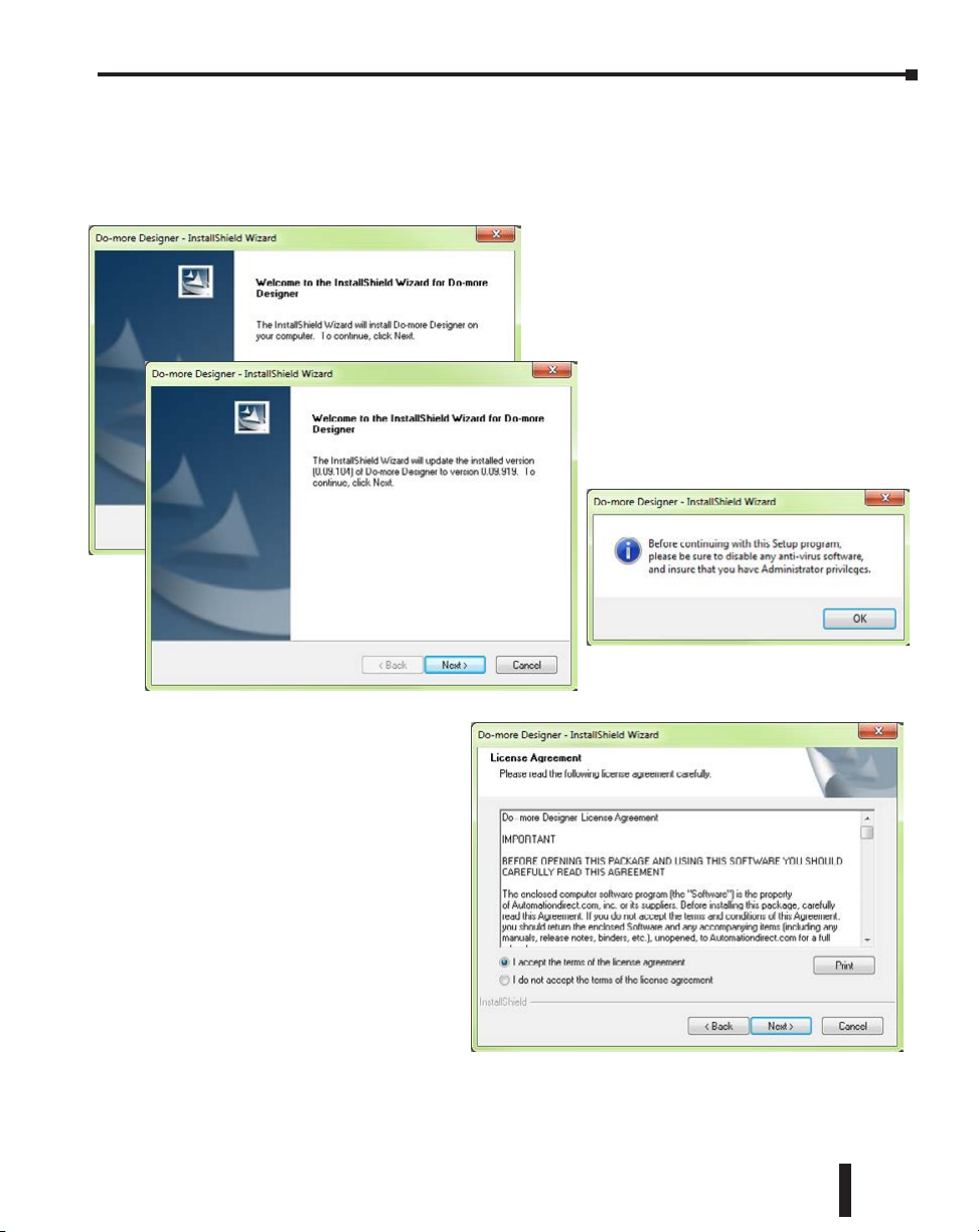
Step 1: Install Do-more Designer Software
Download the Do-more Designer programming software (DM-PGMSW) from our website
at http://automationdirect.com and launch the install procedure. If you already have Do-more
Designer installed, you can just update to version 1.2 or newer to get T1H CPU support.
The first screen that opens is the Welcome
screen seen here. If there are previous versions
of this software already installed, this screen will
detail the version number of the software being
replaced and the one being installed, click Next
to continue.
An alert window will appear requesting
that all anti-virus software be disabled
and also reminding the user that
Administrative restrictions may exist.
Chapter 1: Getting Started
The License Agreement window
will be displayed next. Read over
the agreement, select “I accept the
terms of the license agreement” and
click the Next button to continue.
There is also the option to print the
license agreement if desired. The
print function will print the license
agreement to a .pdf file and save it
in the location you choose.
Do-more T1H Series PLC Hardware User Manual, 1st Edition, Rev. C
1–7
Page 18
Chapter 1: Getting Started
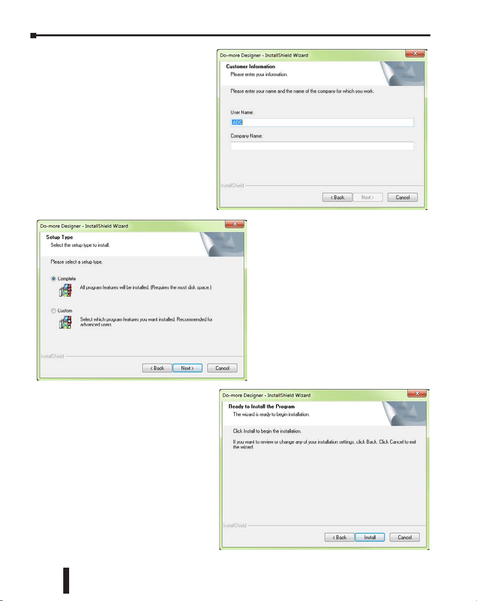
Now the software will ask a little
about you. Please fill in the
information requested on the
Customer Information screen and
click Next to continue.
At this stage, the software will
ask which type of install you
would like to perform. The Select
Type window seen below gives
two options for installation type:
Complete and Custom.
Custom installation allows you to choose which
program features to install, whereas Complete
installation installs all of the program features
available. The Complete installation is selected
by default and is recommended for first-time
users.
Select the installation type desired and click the
Next button to continue.
1–8
The next screen to appear is the
Ready to Install the Program
window. This window is an alert
window, cautioning you that the
program is about to be installed. If
there are any changes that need to
be made to the install settings do
them now before continuing.
To review or change any of the
previous installation selections, click
the Back button to return to the
appropriate window and make the
change. If no changes are necessary
click the Install button to begin the
installation.
Do-more T1H Series PLC Hardware User Manual, 1st Edition, Rev. C
Page 19

Chapter 1: Getting Started
The popup shown here will allow you to choose
whether or not to install a shortcut for the
software on your PC’s desktop. Click Yes or
No to continue with the installation.
The software will now install the
needed files and folders with the Setup
Status window detailing the status of
the installation.
Once the installation has been
successfully completed, the window
below will open. Your software is
now installed and ready to use. The
installation wizard can now be closed
by clicking the Finish button at the
bottom of the window.
Do-more T1H Series PLC Hardware User Manual, 1st Edition, Rev. C
1–9
Page 20
Chapter 1: Getting Started
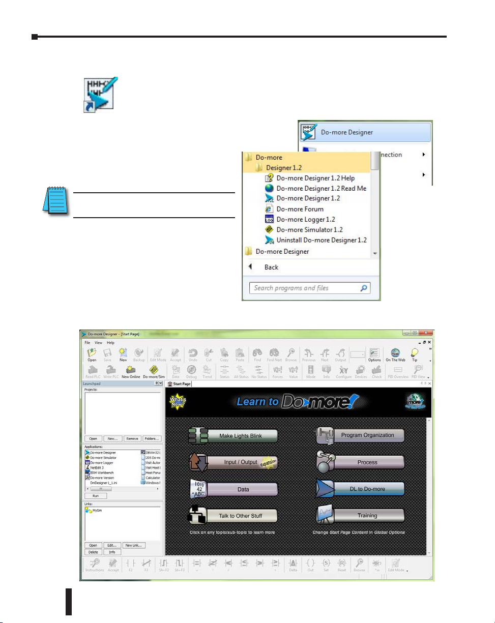
Step 2: Launch Do-more Designer Software
After installing Do-more Designer, launch the software by double clicking the
desktop DM icon.
You can also launch the software from the PC’s Start
menu or All Programs menu. If the software link
is not embedded in the Start menu,
use the path: Start > All Programs >
Do-more > Designer x.x > Do-more
Designer x.x to launch the software.
NOTE: Software version 1.2 or greater is
required.
The Do-more Designer Software will
start up and display the Start Page
shown below. This page consists
of a Launchpad with quick links to
existing projects, software applications
and communications links. There
is also a section containing shortcuts
to important help file topics and the
Do-more Designer simulator application.
1–10
Do-more T1H Series PLC Hardware User Manual, 1st Edition, Rev. C
Page 21
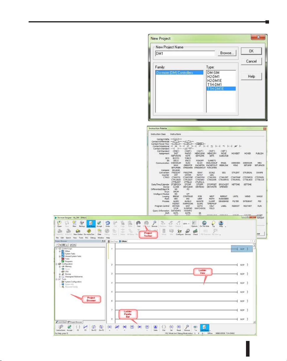
To begin a new project offline select
New from the toolbar on the Start
Page. The New Project window seen
here will open.
Name the new project and select the
type of controller it is intended for.
Use the Browse button to choose a
different location to store the project or
accept the default location. Click OK
after your selections have been made
to continue. The Main programming
window and Instruction Palette shown
below will open.
The Instruction Palette lists all of
the instructions available for use in
your program. A brief explanation of
each instruction is provided once the
instruction is highlighted and a more
detailed explanation is available in the
help file.
The Main programming window
is divided into menus and toolbars
for quick access to configurations,
instructions and other needed items
used during project development.
Chapter 1: Getting Started
Do-more T1H Series PLC Hardware User Manual, 1st Edition, Rev. C
1–11
Page 22
Chapter 1: Getting Started
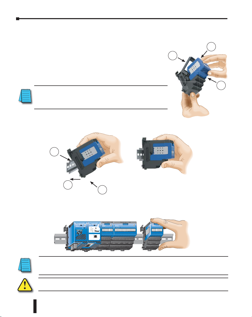
Step 3: Install Hardware
The “Installation and Wiring” chapter of this manual contains detailed information for
the installation of components in your Do-more T1H Series PLC system. The
following summary explains the basic steps for installing modules in a base.
• First, insert module into base:
1. Pull base arm back to allow space for module to enter base.
2. Align module slides with base track.
3. Press module firmly into base.
• Next, mount the components on the DIN Rail:
NOTE: Do not force the modules on the DIN rail. Due to slight size
variations in different manufacturers’ DIN rail, it may be necessary to
first unlatch the locking tab, rotate the module into place, then latch the
locking tab.
1. Make sure the locking tab is in the latched position (pushed in).
2. Hook upper tab over upper flange of DIN rail.
3. Tilt the unit toward DIN rail until it snaps securely to DIN rail.
2
3
1
2
1–12
3
1
• Finally, slide the module assembly into position on the DIN Rail:
Slide the module assembly on the DIN rail until the clip arm attaches securely to the adjacent
module.
T1H-DM1E
TERM
RUN
RUN STOP
USB
I/O
TX
ERR
RX
USB
PGM
PORT
NOTE: One power supply is required in the leftmost component position followed by the CPU. Additional
power supplies should be added between I/O modules as necessary to meet power budget requirements.
Each power supply powers the modules to its right, but is interrupted by the next power supply.
WARNING: Minimize the risk of electrical shock, personal injury, or equipment damage. Always
disconnect the system power before installing or removing any system component.
Do-more T1H Series PLC Hardware User Manual, 1st Edition, Rev. C
Page 23
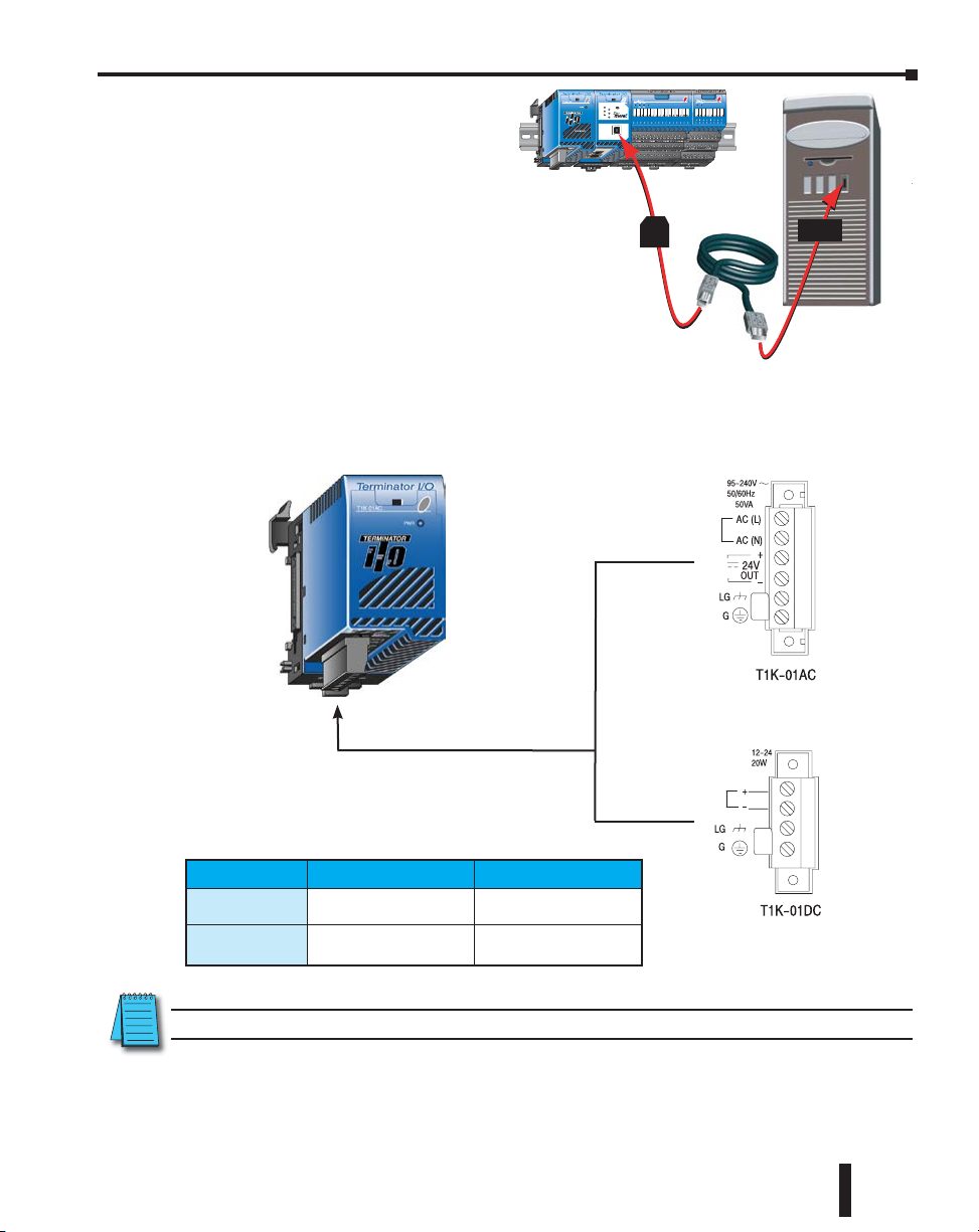
Once all of the modules have been
12/24 VDC Terminal Strip
installed, connect the USB cable. Use a
standard USB cable with Type A
and Type B connectors. (Ethernet and
Serial connections are also available, but are not
shown for this example.)
Step 4: Apply Power to the PLC
Power is supplied to the Do-more T1H Series PLC through the backplane of the base from
the power supply. The following diagram and table show the terminal connections located
on Terminator power supplies and their specifications.
Chapter 1: Getting Started
T1H-DM1E
TERM
RUN
RUNSTOP
USB
I/O
TX
ERR
RX
USB
PGM
PORT
Type
B
110/220 VAC Terminal Strip
Type A
12/24 VDC Terminal Strip
Power Supply T1K-01AC T1K-01DC
Wire Size
Recommended
Torque
Solid: 24–12 AWG
Stranded: 24–12 AWG
4.43–5.31 lb·in
(0.5–0.6 N·m)
Solid: 24–12 AWG
Stranded: 24–12 AWG
4.43–5.31 lb·in
(0.5–0.6 N·m)
NOTE: You can connect either a 115VAC or 220VAC supply to the AC terminals.
Once all of the power wiring has been completed and verified, connect the appropriate voltage
source to the power supply and power up the system. The Do-more T1H Series PLC will
perform a self evaluation once power is applied. Refer to the “Installation and Wiring” chapter
of this manual for more power supply and input wiring information.
Do-more T1H Series PLC Hardware User Manual, 1st Edition, Rev. C
1–13
Page 24
Chapter 1: Getting Started
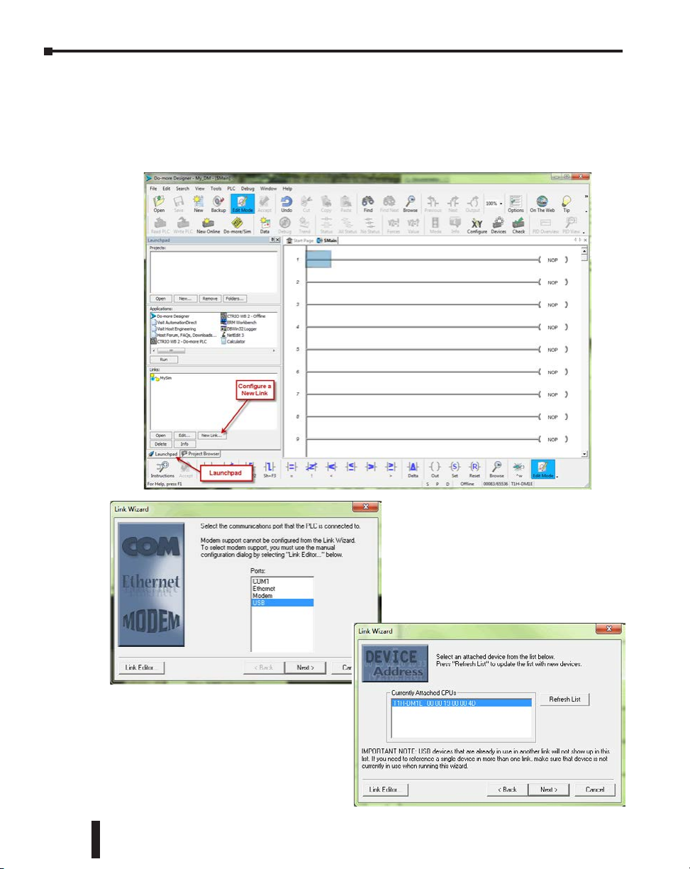
Step 5: Establish Communication
Now that the Do-more T1H Series PLC is powered up, you need to establish a
communications link between the PC and the PLC. The Do-more Designer software
provides a Link Wizard to assist you with configuring this new communications link. To
open the Link Wizard, select the New Link... button in the Links section of the Main Page’s
Launchpad as shown below.
The Link
1–14
Wizard will first ask you to choose which
communications port you will be using.
In this example, we will be using a USB
connection. Select USB, click Next and
the wizard will automatically search for
available CPU’s on that port.
Choose the CPU that you are
programming and select Next. The
Do-more Designer software will create a
link to that controller.
The Link Wizard will now display the
saved settings for this link as seen on
following page.
Do-more T1H Series PLC Hardware User Manual, 1st Edition, Rev. C
Page 25
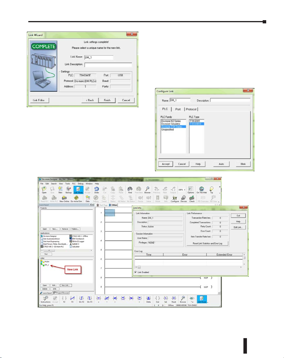
A unique name is required for each link that is
created. Name the new link and, if desired, give it a
description then select Finish.
You can also manually configure each link by
selecting the Link Editor... button from the lower
left corner of the Link Wizard. The Configure Link
dialog will open, as seen below, allowing you to select
PLC types, port parameters, and protocols.
Once you have completed configuring
your communications link, either
manually with the Link Editor or
automatically with the Link Wizard, it will
be available to select in the Links section
of the Launchpad. There you can edit,
enable/disable, delete or view statistics for
that link.
Chapter 1: Getting Started
Do-more T1H Series PLC Hardware User Manual, 1st Edition, Rev. C
1–15
Page 26
Chapter 1: Getting Started
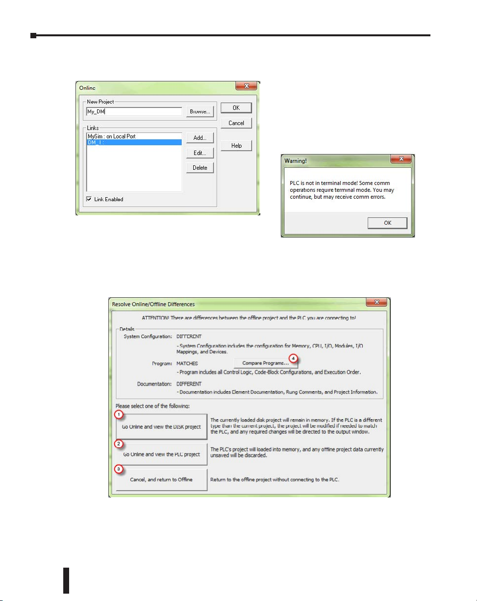
Now select the New Online button and the Online dialog box, seen below, will open. From
this dialog, you are given available communications links to choose from with options to add,
edit disable/enable, or delete links.
You are allowed to continue if you wish or place
the mode selector switch on the CPU module
in the Term position to avoid any unintended
communication errors.
If you were connecting to the CPU module with a project created offline, you may encounter
the message window shown here.
Choose the appropriate link, select OK
and the software will connect to the
Do-more T1H Series PLC. If the mode
selector switch on the CPU module is not
in the Term position when connecting, the
warning shown below will appear.
1–16
Do-more T1H Series PLC Hardware User Manual, 1st Edition, Rev. C
Page 27
Chapter 1: Getting Started
Only with the New Online option does the Do-more T1H Series PLC assume that you are
creating a new project from scratch. With any other method, such as PLC > Connect, the
software will compare the project in the controller with the offline version you have open. If
there are any differences, this warning window will appear detailing the options available for
continuing:
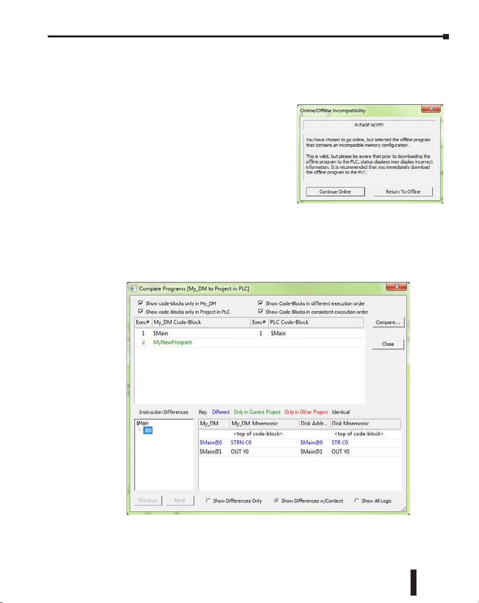
1. Go Online and view the DISK project - This option
will go online with the PLC but display the project
from disk. Status displays may show incorrect
information. If the memory configuration in the diskbased project contains elements that are incompatible
with the memory configuration currently in the
Do-more PLC the message box seen here will be
displayed.
2. Go Online and view the PLC project - The project
from the PLC will be opened by Do-more Designer.
3. Cancel, and return to Offline - This option will cancel the connection attempt and return to the
offline project.
4. Compare Programs... - If you are unsure as to why the two projects are different, then this option
will do a comparison of the projects and detail the differences found. An example comparison is
seen below.
In this example, the PLC project titled My_DM was compared with a project stored on the PC. The
report window shown above illustrates the differences found between the two.
Do-more T1H Series PLC Hardware User Manual, 1st Edition, Rev. C
1–17
Page 28
Chapter 1: Getting Started
According to the report, the PLC project was different in two areas. First, a new code-block was found
only in the PLC project. This new code-block is titled MyNewProgram and is highlighted in green.
The green color represents items that exist only in the Current Project (project in PLC) and not in the
Other (project in PC). Also, the comparison noted that a normally open contact (STR) was changed to
a normally closed contact (STRN) at $Main@0. This item is highlighted in blue which represents items
that are different between the PLC Project and the project in the PC.
Other colors used in the comparison are red, which denotes items that exist only in the project on the
PC and not in the PLC and black which highlights items that are identical in both projects. There are
also numerous checkbox and radio button options available to help you analyze the differences between
projects.
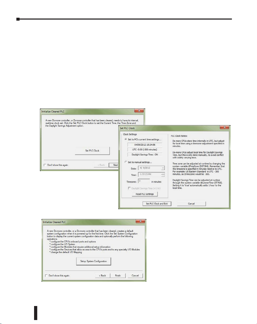
Once you have connected to the CPU either by using the New Online option or using PLC
> Connect for offline projects, you may
encounter the initialization windows
shown here.
1–18
The Set PLC Clock option (above)
allows you to set the internal, realtime clock of the PLC.
The Set PLC Clock window (right)
has options for Timezones and
Daylight Savings Adjustments.
The Setup System Configuration
option (left) allows you to configure the
parameters of the Do-more T1H Series
PLC. I/O module configuration, CPU
ports, and I/O mapping profiles are a
few of the parameters available in the
System Configuration window. Refer
to the following section for Hardware
Configuration options.
Do-more T1H Series PLC Hardware User Manual, 1st Edition, Rev. C
Page 29
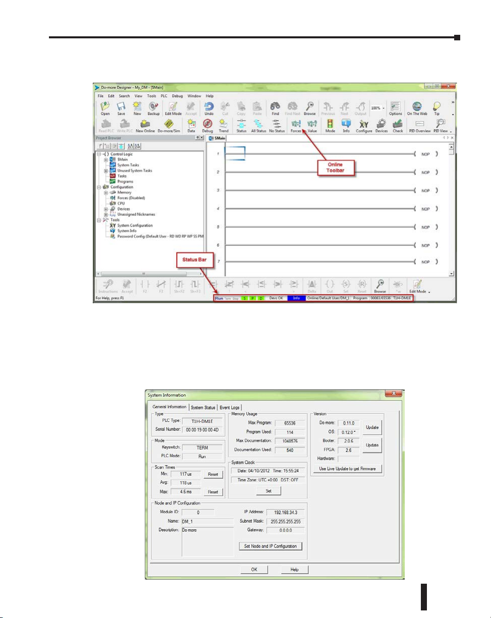
Chapter 1: Getting Started
Once all parameters have been configured, the following programming window will open
with the online toolbar active.
Notice that the status bar indications show PLC type, memory usage, communication status,
PLC errors, PLC mode, etc. Hovering your mouse over the status bar will highlight the items
that are selectable. If you select one of these items, a new window will open with real-time
data and options that are available for that selection.
As an example, the System Information window seen here appears after selecting the Memory
Usage indication from the status bar.
Do-more T1H Series PLC Hardware User Manual, 1st Edition, Rev. C
1–19
Page 30
Chapter 1: Getting Started
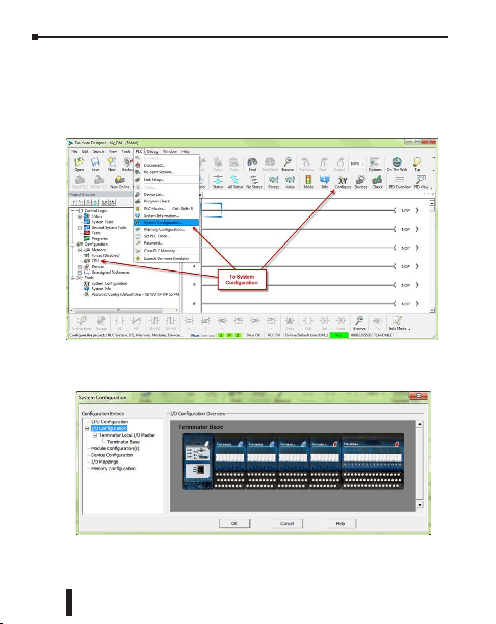
Step 6: Verify Hardware Configuration
Next, you will need to verify the hardware configuration for accuracy. The Do-more T1H
Series PLC has an auto discover feature that will automatically detect the I/O modules
installed. You can see the results of this search by selecting PLC > System Configuration,
double clicking the CPU link under the Configuration tab in the Project Browser, or by
clicking the XY Configure icon in the Project Toolbar.
1–20
On the left side of the System Configuration window is an index of topics titled
Configuration Entries. Click the I/O Configuration tab and you should see an overview of
the modules that the software located, similar to the following.
From here you can verify that the software has detected all of the I/O modules that are
installed.
Do-more T1H Series PLC Hardware User Manual, 1st Edition, Rev. C
Page 31

Chapter 1: Getting Started
The Do-more T1H Series PLC allows the I/O to be manually configured as well. In order to
do so, you must first set the I/O Configuration Mode to manual. Select the Terminator Local
I/O Master tab found under the I/O Configuration tab in the Configuration Entries index.
The Terminator Local I/O
Master Configuration window
shown here will appear. From
here select Manual to configure
the I/O modules that are installed
in the system yourself. It is
important to remember that
the PLC will compare what you
configure with what is installed
and they must match for the PLC
to work properly.
NOTE: If the manually configured I/O modules do not match the installed I/O modules, the PLC will not go
into Run Mode.
After you have set the configuration mode to Manual, select the Terminator Base tab in the
Configuration Entries index. This will take you to the following set up window.
Notice that from this window, you can perform a Manual Scan. When initiated, this scan
will poll the available modules connected to the PC and display the I/O found. The results
can then be altered as you choose.
Do-more T1H Series PLC Hardware User Manual, 1st Edition, Rev. C
1–21
Page 32

Chapter 1: Getting Started
To manually enter your I/O modules into the configuration, right click on the slot the module will
reside in, select Add Module and then choose the module from the drop down list. Once you have
selected the module, it will appear in the slot that was chosen.
1–22
In order to Insert a module manually between two existing modules in the System Configuration
Window, you would follow the same steps as mentioned above but instead of selecting ‘Add
Module’ the selection will be ‘Insert Module’ as seen below.
Do-more T1H Series PLC Hardware User Manual, 1st Edition, Rev. C
Page 33

Chapter 1: Getting Started
After the hardware configuration has been verified select the I/O Mappings tab in the
Configuration Entries index. This option will display the assigned addresses for the
configured modules as seen below.
These X (discrete input), Y (discrete output), WX (analog input) and WY (analog output)
addresses are automatically assigned by Do-more Designer. You have the option to manually
configure these addresses by selecting Manual in the Mapping Mode section at the bottom of
the window.
The Manual Mode Instructions section, also found at the bottom of the window, details the
various color indications associated with this mode.
Do-more T1H Series PLC Hardware User Manual, 1st Edition, Rev. C
1–23
Page 34
Chapter 1: Getting Started
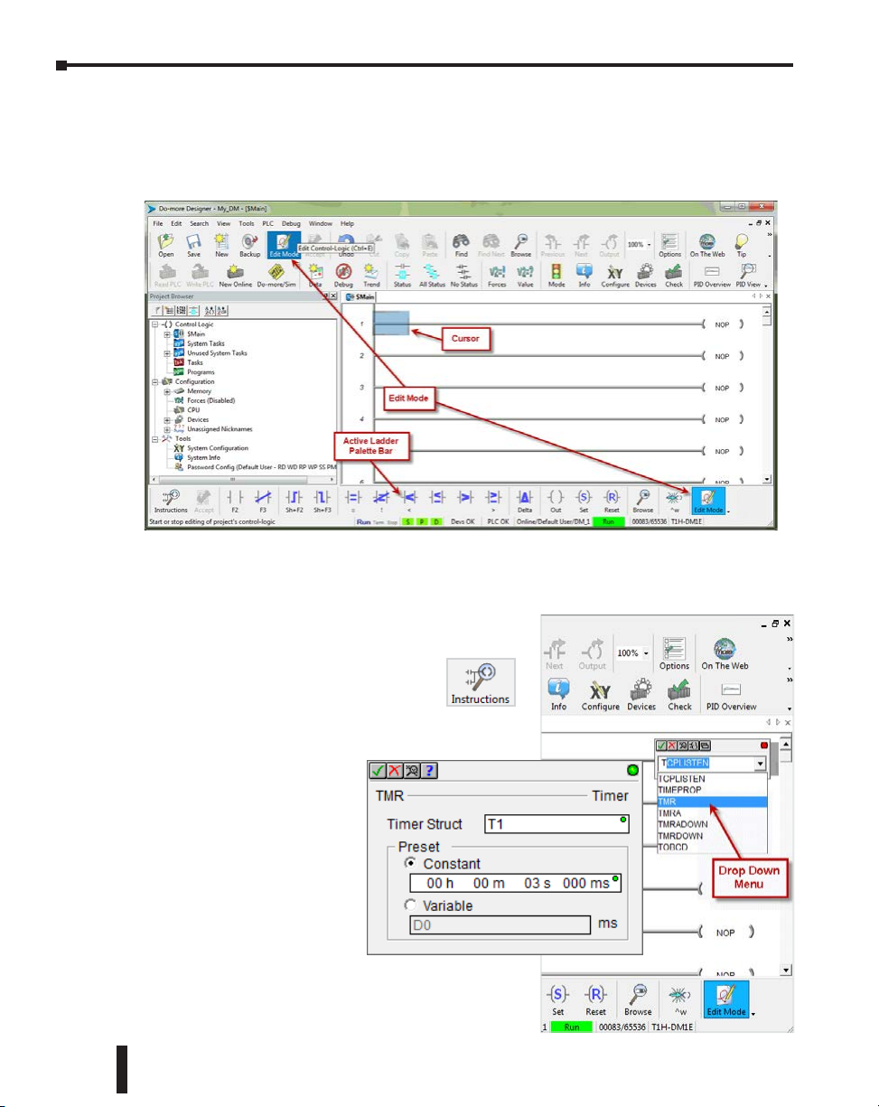
Step 7: Create a Ladder Logic Program
To create a ladder logic program, you must first place the software in Edit Mode. Click the
Edit Mode button found in the Project Toolbar or Ladder Palette Bar or use the shortcut
Ctrl+E.
When in Edit Mode, all of the Ladder Palette Bar’s options will become active and the cursor
in Ladder View will fill in blue. Now, you are ready to begin entering the example ladder
logic below.
1–24
Rung #1
Place the box cursor in the NOP position on Rung #1.
If the Instruction Palette is not open, then
click Instructions from the Ladder Palette
Bar and select the TMR (Timer) or type a
“T” and select TMR from the drop down menu, then
press Enter. Once TMR is selected, a Timer dialog
box appears.
1. Set the Timer Struct to T1.
2. Enter 03 into the Preset
Constant Value for the
seconds (s) preset.
3. Click the checkmark in the
upper left corner to accept.
After clicking the checkmark,
Rung #1 should show the
T1 timer (TMR) instruction
with a preset of 3.000 seconds. A user variable can be
assigned to the preset value if needed.
Do-more T1H Series PLC Hardware User Manual, 1st Edition, Rev. C
Page 35
Chapter 1: Getting Started
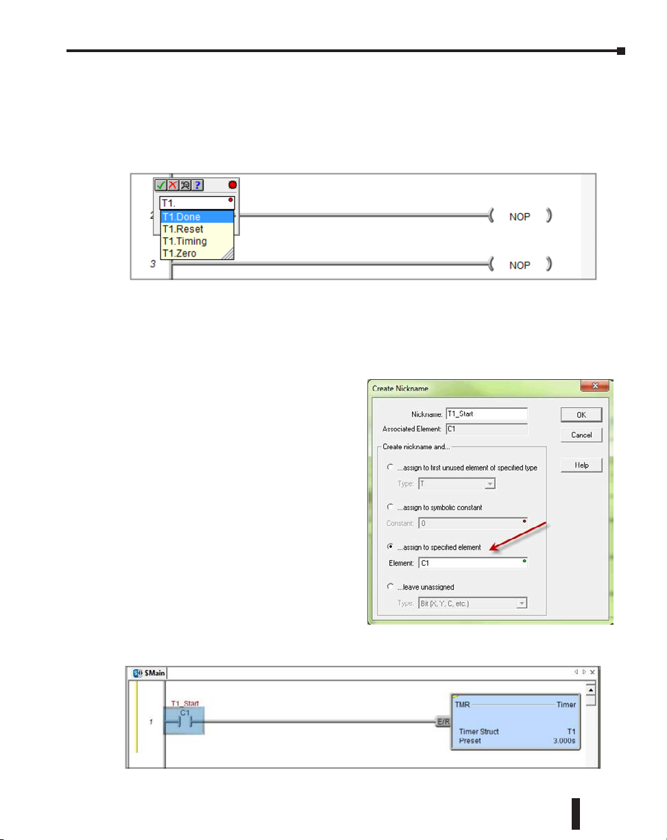
Since a Timer is a structure it has predefined elements associated with it. Elements such as
.Acc (accumulated time), .Done (the completion bit) and .Timing (the timer is enabled and
timing). Therefore, if “T1.” is entered into any contact name the Auto-Complete feature
of Do-more Designer will display all applicable bit (boolean) selections available for that
structure. Selecting the .Done option, as seen below, will assign this element to the contact
and the contact name will be T1.Done.
This feature works for all structures including: timers, counters, PID loops and strings.
Many system data types such as, $Main and $FirstScan, as well as user-created devices like
ECOM, CTRIO, or SERIO modules can also use this feature. See the Do-more Designer
Help file for more information on structures.
Now place the box cursor in the leftmost
column of Rung #1. Type in a meaningful
nickname, such as “T1_Start”, and press
Enter or select the Normally Open Contact
(F2) from the Ladder Palette Bar, enter
“T1_Start” for the name and click the
checkmark in the upper left corner. Either
method will open the Create Nickname
dialog seen here. Select the third option to
assign the nickname to a specified element,
type the desired memory bit for this
contact (C1) and select OK.
Rung #1 should now appear as follows:
Do-more T1H Series PLC Hardware User Manual, 1st Edition, Rev. C
1–25
Page 36

Chapter 1: Getting Started
With the cursor in the position to the right
of contact T1_Start, you are going to begin
drawing a branch circuit. Under the Edit
drop down menu, select Wire, then select
Down. Notice the shortcuts that are available
for wire drawing. The wire that should now
appear in your ladder could have also been
drawn using the shortcut Ctrl+Down Arrow.
NOTE: There are also Delete Wire options in
the Edit drop down menu that are used to
erase any wires not needed.
1–26
Now place the cursor in the space to the left of the new line and select another normally open
contact.
Type in the nickname “T1_Manual”
and assign bit C2. Select OK to
accept and Rung #1 should now
resemble the rung seen on the
following page.
Do-more T1H Series PLC Hardware User Manual, 1st Edition, Rev. C
Page 37

Chapter 1: Getting Started
Rung #2
Place a normally open contact in the first position of Rung #2. This contact will be tied to
the Done bit of timer T1. Therefore, the name for this contact should be entered as “T1.
Done”. There should be no Create Nickname dialog as seen with the earlier normally open
contacts.
Lastly, you will need to add an Out coil to the end of Rung #2. Place the cursor at the end
of the rung and either select Out from the Ladder Palette Bar or just type “OUT” and select
the Out instruction from the drop down menu. Next, choose which bit will be tied to this
coil. Tie this coil to the physical output Y1 by typing “Y1” and click the check mark.
The ladder program should now look like the following. When either the T1_Start or
T1_Manual contact is energized, the timer will begin timing. When it times out, contact
T1_Done will energize and the output coil Y1 will turn on. Note that an END instruction
is not required.
Do-more T1H Series PLC Hardware User Manual, 1st Edition, Rev. C
1–27
Page 38

Chapter 1: Getting Started
The yellow bar in the margin signifies logic that has not been accepted. So once you have
verified your logic, click the Accept button in the Project Toolbar or the Ladder Palette Bar
to accept the changes.
You should now see blue and green bars,
shown below, signifying that the logic
has not been downloaded to the CPU or
saved.
1–28
Now exit the Edit mode by clicking the Edit Mode button once again or by pressing ESC on
the keyboard.
Do-more T1H Series PLC Hardware User Manual, 1st Edition, Rev. C
Page 39
Chapter 1: Getting Started
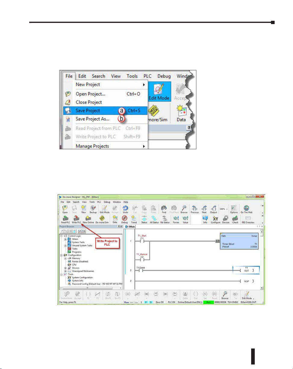
Step 8: Save a Project
Save the project by selecting (a) Save Project (Ctrl+S) from the File drop down menu. Or
save the file under a different name or in a different location by selecting the (b) Save Project
As... option.
Step 9: Write Project to the Do-more T1H Series PLC
Now that you have created the example ladder logic program, you can write the program to
the PLC. To do so, click the Write PLC button in the Project Toolbar.
If the Write PLC button is not active, then you must first connect to the PLC to activate
the online portion of the Project Toolbar (see the “Establish Communication” section of
this chapter). If you have altered the System Configuration, which includes the hardware
configuration, in any way, then the PLC must be taken out of Run mode in order to process
the download.
Do-more T1H Series PLC Hardware User Manual, 1st Edition, Rev. C
1–29
Page 40
Chapter 1: Getting Started
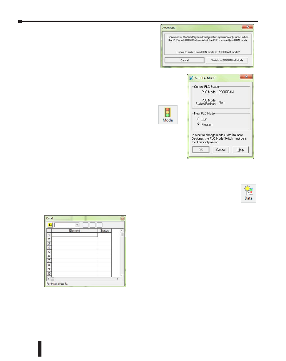
The message seen here will appear asking you to
verify if this is a good time to do so. Since this
is the setup phase of this system, select Switch to
Program Mode and continue with the download.
If this system was previously commissioned and
in use, then you would need to verify that the
process it is controlling can be interrupted at this time before
continuing.
Download the project and once the download is finished,
assuming there are no errors, the Do-more T1H Series PLC
should return to Run mode. If at any time you
need to change the PLC mode, select the Mode
icon in the Project Toolbar, click the Mode
Status indication in the Status Bar or select PLC
> PLC Modes....
The PLC Modes window shown here will open displaying
the current mode the PLC is in with options to change it
to either Run or Program mode. Click OK to accept the
change or Cancel to exit.
Step 10: Testing Project Using Data View
With the project successfully downloaded into the Do-more T1H Series PLC, you
can now test the function of the ladder program using the Data View tool. To start,
you need to open a new Data window in the software. To do so, click the Data icon
in the Project Toolbar, select Debug > Data View > New or press Ctrl+Shift+F3.
1–30
The Data View window seen here will open. This
window will open in the project browser section of the
programming window but it can be relocated anywhere
on the screen by clicking the title bar and dragging it to a
new location.
Now enter the elements that you wish to monitor. On
line one type “C1” under the Element column and press
Enter. You will see the C1 change to the variable name
associated with it or T1_Start. On line two type the
element “C2” and on line three type “Y1”.
With the ladder elements entered into the Data View window, you now need to activate their
status. To do so, click the All Status icon on the Project Toolbar or select Debug > All Status
On. The All Status On option will not only activate the status of the Data View window but
also the status of the ladder program as seen on the following page.
Do-more T1H Series PLC Hardware User Manual, 1st Edition, Rev. C
Page 41
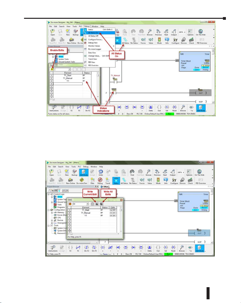
Chapter 1: Getting Started
The next step is to enable edits within the Data View window. To do so, click the yellow box
with the “E” found in the top left corner of the Data View window, as seen above. The Edits
column is now added to the Data View window.
The Edits column allows you to make changes to the current values of the elements listed.
T1_Start’s current value is OFF. Click the ON button under the Edits column and the
Write Current Edit and the Writes All Edits buttons will appear at the top of the window.
These buttons will write individual or all edits made in the Data View window to the PLC.
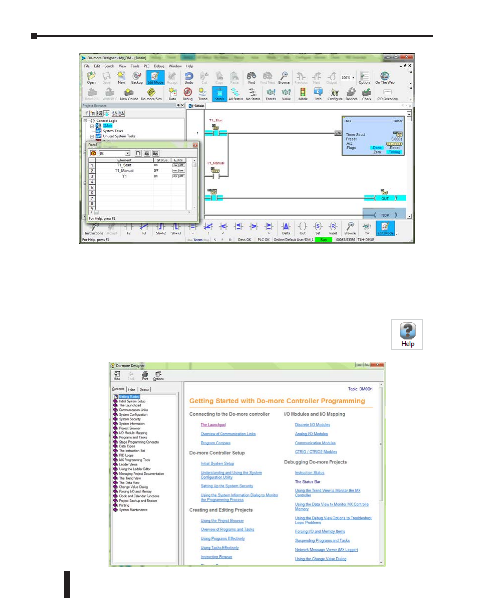
Click the Write Current Edit to PLC button and confirm it. This will write the new value
to T1_Start. Once T1_Start changes to an ON state, the timer (T1) will begin to time and
quickly reach the preset. As soon as the preset is reached, the done bit, T1.Done, will turn
ON causing output Y1 to also turn ON as seen on the following page. Now write an OFF to
T1_Start and watch as the timer and Y1 reset.
Do-more T1H Series PLC Hardware User Manual, 1st Edition, Rev. C
1–31
Page 42
Chapter 1: Getting Started
Congratulations, you have now programmed, downloaded and tested a ladder logic program
for the Do-more PLC. Feel free to experiment with a program of your own and don’t forget
that the software Help file is an essential tool to use when programming your controller.
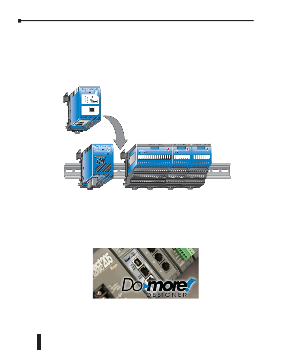
Accessing the Help File
The software Help file, seen below, is available as a quick reference or detailed
guide to the many features and capabilities of the Do-more PLC. To access the
Help File select the Help File icon from the Project Toolbar, choose Help from
the Help menu drop down or use the shortcut F1.
1–32
Do-more T1H Series PLC Hardware User Manual, 1st Edition, Rev. C
Page 43

Do-more PLC
HarDware overview
In This Chapter:
Do-more T1H Series PLC Overview ����������������������������������������������������������������������������� 2–2
Module Compatibility ������������������������������������������������������������������������������������������������ 2–3
Communications �������������������������������������������������������������������������������������������������������� 2–4
Chapter
Chapter
Chapter
2
2
2
Page 44
Chapter 2: Do-more PLC Hardware Overview
Do-more T1H Series PLC Overview
The Do-more T1H Series PLC is the latest PLC series released as part of the Do-more PLC
family. The Do-more T1H Series PLC combines the modular and space-saving package
of our Terminator I/O line with the new Do-more T1H Series CPU module to create
a versatile, stand-alone control system. Using Do-more Designer as a foundation, the
T1H Series PLC system provides a powerful, flexible instruction set, inside a user friendly
programming environment.
TERM
RUNSTOP
USB
TX
RX
USB
PGM
Do-more T1H
CPU Module
T1H-DM1E
RUN
I/O
ERR
PORT
Terminator I/O system with Power Supply and I/O modules (Base Controller removed)
The Do-more T1H Series PLC is designed around a new control engine with a new,
advanced Do-more Instruction Set for ladder programs. The new Do-more Designer
software, with advanced programming and monitoring features, will be used to create your
new programs.
2–2
Do-more T1H Series PLC User Manual, 1st Edition, Rev. C
Page 45
Chapter 2: Do-more PLC Hardware Overview
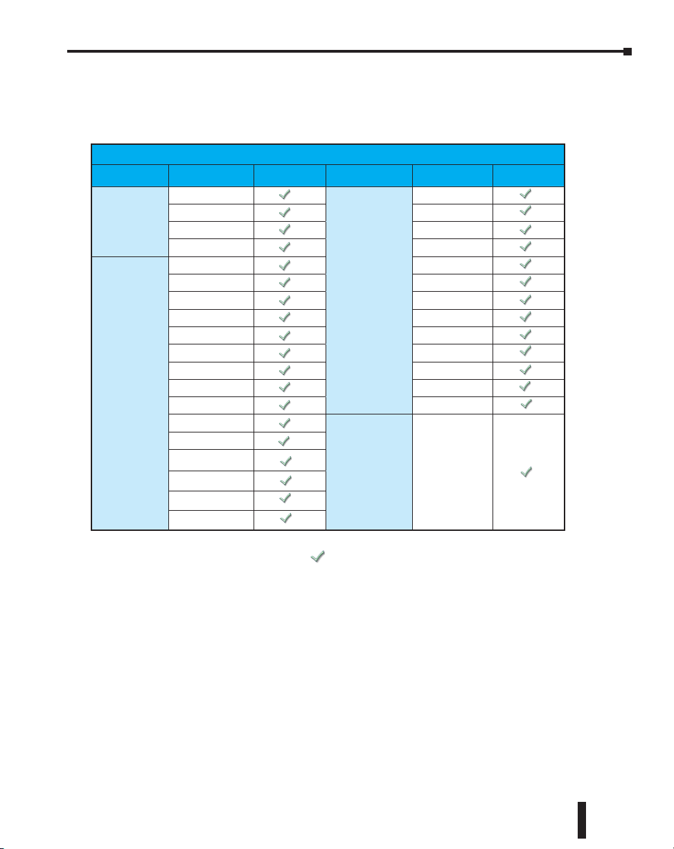
Module Compatibility
The following table shows which Terminator I/O product line components are supported by
the Do-more T1H-DM1 and T1H-DM1E CPUs.
Module Compatibility Table
Module Part Number
T1K-08B
Base Units
Discrete I/O
Modules
T1K-08B-1 T1F-08AD-2
T1K-16B T1F-16AD-1
T1K-16B-1 T1F-16AD-2
T1K-08ND3 T1F-16RTD
T1K-16ND3 T1F-16TMST
T1K-08NA-1 T1F-14THM
T1K-16NA-1 T1F-08DA-1
T1K-08TD1 T1F-08DA-2
T1K-16TD1 T1F-16DA-1
T1K-08TD2-1 T1F-16DA-2
T1K-16TD2-1 T1F-8AD4DA-1
T1H-08TDS T1F-8AD4DA-2
T1K-08TA
T1K-16TA
T1K-08TAS
T1K-08TR
T1K-16TR
T1K-08TRS
Status Module Part Number Status
T1F-08AD-1
Analog I/O
Modules
Specialty
Modules
T1H-CTRIO
= Supported
Do-more T1H Series PLC User Manual, 1st Edition, Rev. C
2–3
Page 46

Chapter 2: Do-more PLC Hardware Overview
Communications
The Do-more T1H Series PLC supports many communication protocols. The following
table shows which CPU module communications port supports each protocol.
Protocols
Do-more Designer Programming
CPU Modules
T1H-DM1 / T1H-DM1E
USB Port
Yes Yes Yes
RS-232
Serial Port
T1H-DM1E
Ethernet
Port
Modbus/RTU Client (Master)
Modbus/RTU Server (Slave)
Modbus/TCP Client (Master)
Modbus/TCP Server (Slave)
DirectLOGIC RX/WX Client (Master)
DirectLOGIC RX/WX Server (Slave)
K-Sequence Server (Slave)
DirectNET Server (Slave)
HEI Ethernet I/O Master
SMTP (EMail) Client w/Authentication
Simple Network Time Protocol (SNTP) Client
Do-more/PEERLINK
Do-more Time Synchronization Protocol (Client, Server,
Alternate Client)
Do-more Logger/UDP
Serial ad-hoc ASCII/Binary Programatic Control
UDP ad-hoc Programmatic Control
Yes
Yes
Yes
Yes
Yes
Yes
Yes
Yes
Yes
Yes
Yes
Yes
Yes
Yes
Yes
2–4
TCP Client Programmatic Control
TCP Server Programmatic Control
Blank = Not Supported
Do-more T1H Series PLC User Manual, 1st Edition, Rev. C
Yes
Yes
Page 47

Chapter
Chapter
SpecificationS - cpU
Chapter
ModUleS
3
3
3
In This Chapter:
CPU Specifications �������������������������������������������������������������������������������������������������������� 3–2
Communications Ports Specifications �������������������������������������������������������������������������� 3–4
Port 1 Specifications (USB) ������������������������������������������������������������������������������������������ 3–4
Port 2 Specifications (Serial) ���������������������������������������������������������������������������������������� 3–4
Port 3 Specifications (Ethernet) ����������������������������������������������������������������������������������� 3–5
Ethernet I/O ������������������������������������������������������������������������������������������������������������������ 3–6
Status Indicators ����������������������������������������������������������������������������������������������������������� 3–8
Mode Switch Functions ������������������������������������������������������������������������������������������������ 3–8
DIP Switch Specifications ��������������������������������������������������������������������������������������������� 3–9
Battery Replacement �������������������������������������������������������������������������������������������������� 3–12
Page 48

Chapter 3: Specifications - CPU Modules
S
STAT
CPU Specifications
CPU General Specifications
Feature
Total Memory (bytes)
Ladder Memory
(instruction words)
V-Memory (words)
Non-volatile V Memory (words)
D-memory (DWORDs)
Non-volatile D Memory (DWORDs)
R-memory (REAL DWORDs)
Non-volatile R Memory
(REAL DWORDs)
Boolean execution
Stage Programming
Number of Stages
Handheld Programmer
Programming Software for Windows
Built-In communications ports
Program Memory
Total I/O points available
Max Number of Local I/O Modules
Local I/O points available
Ethernet I/O Discrete points
Ethernet I/O Analog I/O Channels
Max Number of Ethernet slaves per
PLC
I/O points on Ethernet I/O
Discrete I/O Module Point Density
Number of instructions available
Control relays
Special relays (system defined)
Special registers (system defined)
Timers
Counters
System Date/Time structures
T1H-DM1
65,536 instruction words
Configurable up to 65536 (4096 default)
Configurable up to 65536 (4096 default)
Configurable up to 65536 (4096 default)
Configurable up to 65536 (4096 default)
Configurable up to 65536 (4096 default)
Configurable up to 65536 (4096 default)
128 per Program code-block; number of code-blocks
X, Y, each configurable up to 65536 (2048 default); WX,
configurable to memory limit
USB, RS-232
WY (analog in/out) each configurable up to
>160 >170
Configurable up to 65536 (2048 default)
Configurable up to 65536 (256 default)
Configurable up to 65536 (256 default)
T1H-DM1E
262,144 bytes
50µs
Yes
No
FREE Do-more Designer
USB, RS-232, Ethernet
(10/100 Base-T)
Flash ROM
65536 (256 default)
16
256
131,072
32,768
16
32,768
8/16
1024
512
8
T1H-DM1
TAT
T1H-DM1
T1H-DM1E
T1H-DM1E
3–2
Do-more T1H Series PLC Hardware User Manual, 1st Edition, Rev. C
Page 49

CPU General Specifications (continued)
Feature T1H-DM1
User Date/Time structures
ASCII String/Byte buffer structures
Modbus Client memory
DL Classic Client memory
Immediate I/O
Interrupt input (hardware / timed)
Subroutines
Drum Timers
Table Instructions
Loops
Math
ASCII
PID Loop Control, Built In
Time of Day Clock/Calendar
Run Time Edits
Supports True Force
Internal Diagnostics
Password security
System error log
User error log
Battery backup
Chapter 3: Specifications - CPU Modules
T1H-DM1E
Configurable up to 65536 (32 default)
Configurable up to memory limit (192 default)
Yes, configurable up to memory limit, default 1024 input bits, 1024 coil bits, 2048 input
Up to memory limit, default 512 X, 512 Y, 512 C, 2048 V
>60 operators and functions: Integer, Floating Point, Trigonometric, Statistical, Logical,
Yes, IN/OUT, Serial, Ethernet TCP and UDP; 11 output script commands
registers, 2048 holding registers
No
No
Program and Task code-blocks, up to memory limit
Yes, up to memory limit
Yes
FOR/NEXT, WHILE/WEND, REPEAT/UNTIL loops
Bitwise, Timing
Yes, configurable to memory limit (over 2,000)
Yes
Yes
Yes
Yes
Multi-user, credentialed, session-based security
Yes
Yes
Yes (Battery included)
Do-more Designer V1.2 or newer must be used with these Do-more T1H CPU modules.
Do-more T1H Series PLC Hardware User Manual, 1st Edition, Rev. C
3–3
Page 50
Chapter 3: Specifications - CPU Modules
Communications Ports Specifications
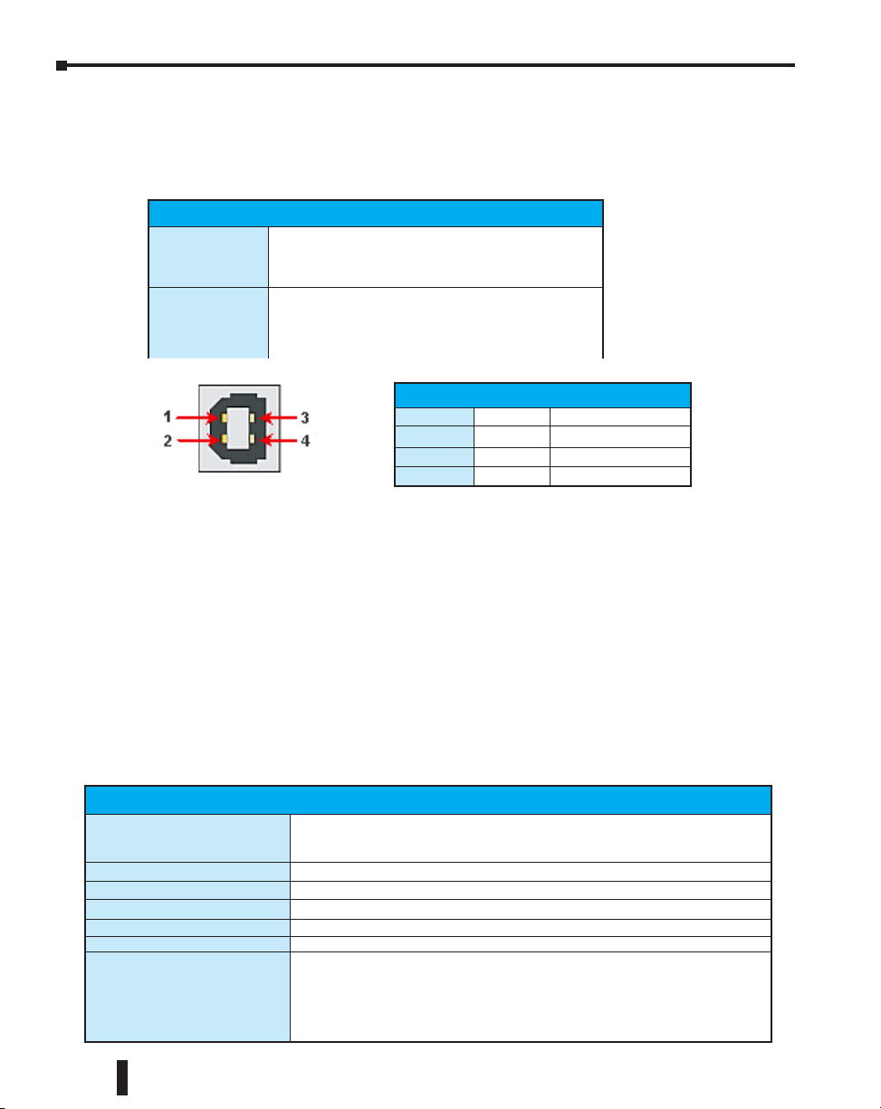
Port 1 Specifications (USB)
USB Port: This port has a USB Type B female connector and requires a USB Type A-B cable.
• Do-more programming protocol only
USB Type B Slave Input Specifications
Description Standard USB 2.0 Slave input for programming and
online monitoring only, with built-in surge protection. Not
compatible with older full speed USB devices.
Cables
(ADC part #)
USB Type A to USB Type B:
USB-CBL-AB3 (3ft)
USB-CBL-AB6 (6ft)
USB-CBL-AB10 (10ft)
USB-CBL-AB15 (15ft)
USB Port 1
1
2
3
4
5V Bus Voltage Sense
D- Data D+ Data +
0V Ground
Port 2 Specifications (Serial)
RS-232 Port: Serial RS-232 multipurpose communications port:
• Full-duplex
• 1024B buffer
• RJ-12 connector
RJ-12 style connector used for:
• Do-more programming protocol
• Modbus RTU Master connections
• Modbus RTU Slave connections
• ASCII Incoming and Outgoing communications
• Custom Protocol Incoming and Outgoing communications
RS-232 Specifications
Description Non-isolated, full duplex RS-232 DTE port used for programming, online monitoring
Communications
+5V Cable Power Source 220mA maximum at 5V, ±5%. Reverse polarity and overload protected.
Maximum Output Load (TXD/RTS)
Minimum Output Voltage Swing ±5V
Output Short Circuit Protection ±15mA
Cable Options D2-DSCBL
or can connect the CPU as an ASCII or Modbus RTU master or slave to a peripheral
device. Includes ESD and built-in surge protection.
1200, 2400, 4800, 9600, 19200, 38400, 57600, and 115200 Baud
3kV, 1,000pf
USB-RS232 with D2-DSCBL
FA-CABKIT
FA-ISOCON for converting RS-232 to isolated RS-422/485
EA-MG-PGM-CBL
3–4
Do-more T1H Series PLC Hardware User Manual, 1st Edition, Rev. C
Page 51

Chapter 3: Specifications - CPU Modules
RS-232 Port 2
1
2
3
4
5
6
0V Power (-) connection (GND)
5V Power (+) connection (220mA max)
RXD Receive Data (RS-232)
TXD Transmit Data (RS-232)
RTS Request to Send (RS-232)
CTS Clear to Send (RS-232)
Port 3 Specifications (Ethernet)
Ethernet Port: Programming and Modbus TCP Client/Server port with 10/100 Base-T
Ethernet RJ45 connector.
RJ-45 style connector used for:
• Do-more programming protocol
• Modbus TCP Client connections (Modbus requests sent from the CPU)
• Modbus TCP Server connections (Modbus requests received by the CPU)
• Ethernet I/O Master
Ethernet Specifications
Description Standard transformer isolated Ethernet port with built-in surge protection
Transfer Rate 10/100 Mbps
Cables Use a Patch (Point to Point) cable when a switch or hub is used. Use a
for programming, online monitoring, Modbus/TCP client/server connections
(fixed IP or DHCP) and Ethernet I/O capabilities.
Crossover cable when a switch or hub is not used.
NOTE: The Ethernet port can support all the functions listed above at the same time. However, it is important
to consider the implications to network traffic and network topology. Since there is just one Ethernet port
available, it will not be possible to use multiple functions and have an isolated network for Ethernet I/O, as is
recommended. Utilize the adjustable poll rates of Ethernet I/O and Modbus TCP Clients (if auto-polling) to
limit the impact on your network.
8
1
NOTE: The above diagram illustrates the standard wire positions in the RJ45 connector. It is recommended
that all 10/100 Base-T cables be Category 5, UTP cables.
Do-more T1H Series PLC Hardware User Manual, 1st Edition, Rev. C
3–5
Page 52

Chapter 3: Specifications - CPU Modules
Ethernet I/O
The T1H-DM1E CPU’s built-in Ethernet port can be configured as an Ethernet I/O
master. The Ethernet I/O feature allows expansion beyond the local chassis to slave I/O
using the onboard high-speed Ethernet link.
The onboard Ethernet port can support up to 16 slave devices. The slave I/O modules
supported are:
• H2-EBC100
• T1H-EBC100 (Terminator I/O)
• GS-EDRV100 (GS Drives)
The Ethernet I/O network uses Category 5 UTP cables for cable runs up to 100 meters
(328 ft.) with extended distances achieved through Ethernet switches.
Ethernet I/O Example
Stride
Ethernet
Switch
Do-more T1H-DM1E CPU
T1H-DM1E
TERM
RUN
RUN STOP
USB
I/O
TX
ERR
RX
USB
PGM
PORT
3–6
C-more Operator
Interface
GS-EDRV100
Terminator I/O
with T1H-EBC100
Module
GS
Drive
Do-more T1H Series PLC Hardware User Manual, 1st Edition, Rev. C
DirectLOGIC
DL205 I/O with
H2-EBC100
Module
Page 53

Chapter 3: Specifications - CPU Modules
Ethernet I/O functionality is enabled through the System Configuration
dialog of Do-more Designer.
Under the PLC drop down menu, select System Configuration. Then,
from the System Configuration window select the CPU Configuration
option under the Configuration Entries column. Finally, left-click the
Enable Ethernet I/O Master checkbox in the Ethernet I/O Master section
of the T1H-DM1E CPU Configuration window as seen below.
For more information on the setup, use and options available with Ethernet I/O, refer to the
Ethernet I/O Master section of Do-more Designer Help File topic DMD0247.
Do-more T1H Series PLC Hardware User Manual, 1st Edition, Rev. C
3–7
Page 54

Chapter 3: Specifications - CPU Modules
T1H-DM1E
100
ACT
IVI
TY
Status Indicators
Do-more T1H CPU modules have multi-color LEDs that are used to visually provide
operational status to the user.
STAT
ACTIVITY
RS232
SERIAL PORT
10/100 BASE-T
ETHERNET PORT
In addition to the individual definition of each LED, there are times when the controllers will
use combinations of the LED ON/OFF state and colors to convey status information. The
following combinations use some or all of the LEDs:
• STAT LED is blinking RED for (15 seconds) - Do-more Designer can blink the STAT LED for 15
seconds to verify that a communication link is targeting the correct controller.
• All six (6) of the LEDs are ON and the color of each LED is GREEN - indicates the operating
system has started running.
• All six (6) of the LEDs are cycling through RED and GREEN, in a circular ‘chase’ pattern indicates the operating system is initializing.
• The left-most three (3) LEDs are cycling through RED and GREEN, in a ‘bouncing ball’ pattern
- indicates the controller is running only the boot loader and is NOT going to load and run the
operating system. The most likely cause is having DIP switch #1 in the ON position.
• All six (6) of the LEDs are ON and the color of each LED is RED - indicates the hardware
watchdog timer has expired because the controller’s operating system has stopped running.
MBIT
LED Indicators
Indicator Status Description
RUN
ROM
STAT*
USB
TX
RX
ACTIVITY
100 MBIT
* See Do-more software manual to further investigate what type of error has occurred.
Green CPU is in RUN Mode
Yellow Forces are Active
Yellow CPU is updating Non-volatile Memory
Red* CPU Fatal Error
Yellow Low Battery
Green Status OK (good)
Green USB Receive Activity
Yellow USB Transmit Activity
Green RS-232 Transmit Activity
Green RS-232 Receive Activity
Green Ethernet Port Activity
Yellow
Ethernet Port communicating at 100
MBIT Rate
Mode Switch Functions
3–8
Mode Switch Functions
Mode Switch Position CPU Action
RUN (Run Program)
TERM (Terminal)
STOP (Stop Program)
CPU is forced into RUN Mode if no errors are encountered.
RUN, PROGRAM and the DEBUG modes are available. In
this mode, the mode of operation can be changed through
the Do-more Designer Software.
CPU is forced into STOP Mode.
Do-more T1H Series PLC Hardware User Manual, 1st Edition, Rev. C
Page 55
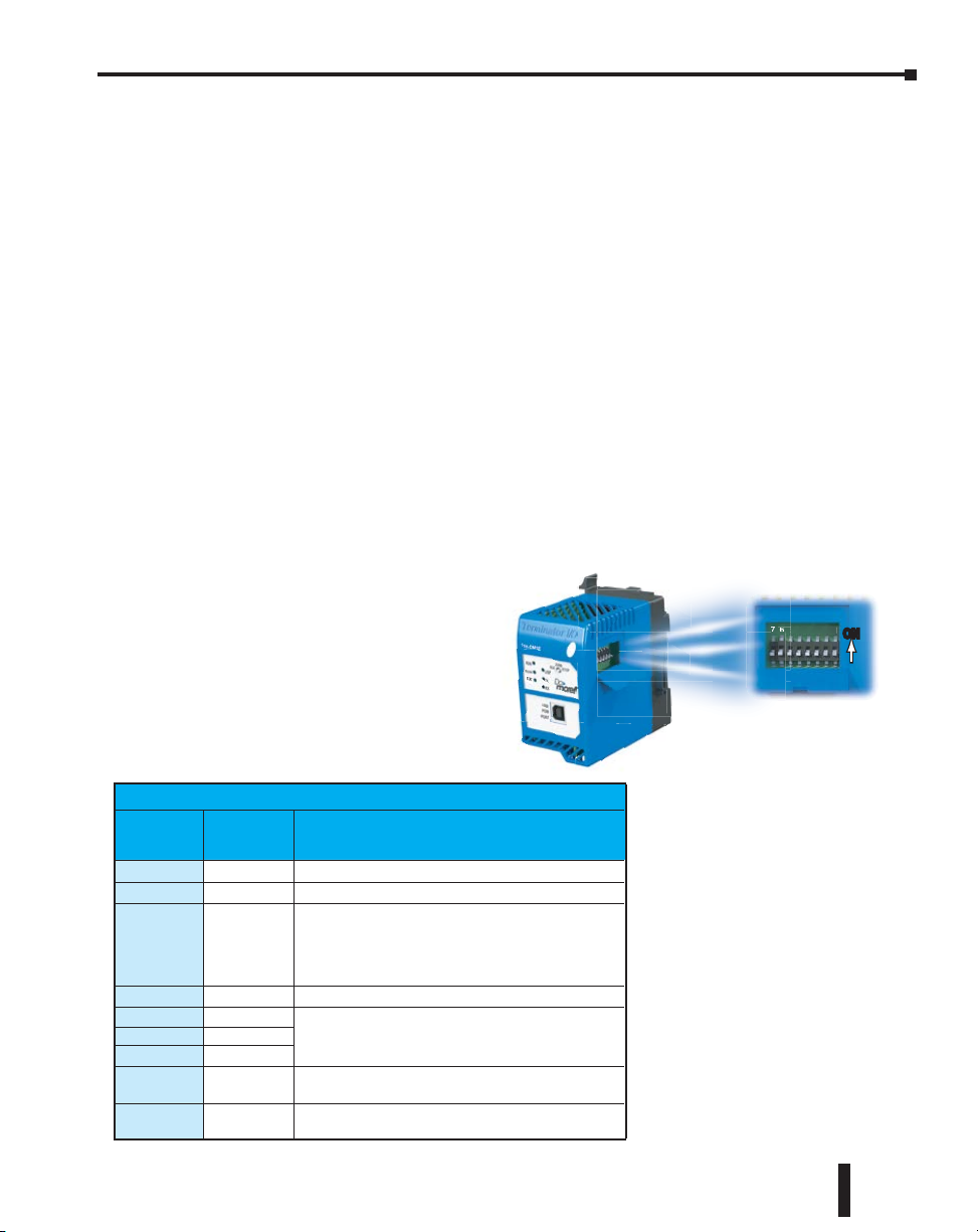
As mentioned in the previous table, the CPU mode can also be changed through the
ON
6567
programming software if the mode switch is placed in the TERM position. In this position,
the CPU can be changed remotely between the Run and Program modes. For more
information on changing CPU modes through the software, see the “Step 9: Write Project to
the Do-more PLC” section of Chapter1 “Getting Started”.
When power is applied to the system, the controller will go through it’s power-up sequence
then either stay in Program mode if the mode switch is in the STOP position, or attempt to
go to Run mode if the mode switch is in the RUN position.
If the mode switch is in the TERM position, the controller will return to the last operational
mode before power was lost. For example, if the controller was in Run mode when power
was lost, when power is restored and the mode switch is in the TERM position, the controller
will attempt to return to Run mode.
DIP Switch Specifications
Do-more controller’s circuit board has a block of DIP switches that are used to perform
various debug and reset operations. The DIP switch settings are only read when the system
is first powered up. Changing the settings of the DIP switches requires that the system
containing the controller be powered down and the CPU removed. The DIP switches can
then be changed as required. The DIP switch block is located on the right side of the CPU
under a small cover. Once the switches have been set, the CPU can then be reinstalled in the
system and powered back up.
The default position for all of the
DIP switches is OFF. The table
below describes the position and
function associated with each DIP
switch.
Chapter 3: Specifications - CPU Modules
76543210
ONON
DIP Switch Settings
Switch
Number
0
1
2
3
4
5
6
7
All 8
Switch
Position
ON Load the last copy of the operating system.
ON Do not load an Operating System, stay in the Booter.
Disable the hardware watchdog timer - the hardware watchdog
is always enabled, but this switch allows the user to override the
ON
ability of the Force Watchdog Error (WATCHDOG) and Debug
Mode to generate a Watchdog condition.
ON Disable ability to update the firmware and/or gate array.
ON
ON
Reserved
ON
Reset the TCP/IP Network Settings to factory default values -
ON
Must be used with DIP #1
Clears everything from the controller
ON
(see details in the following pages)
Function
Do-more T1H Series PLC Hardware User Manual, 1st Edition, Rev. C
Do-more T1H controllers
make use of combinations of
DIP switch settings and the
Mode switch on the front of the
controller to perform two reset
functions. These reset functions
can only be performed when the
controller is in the boot loader.
3–9
Page 56

Chapter 3: Specifications - CPU Modules
The following sequence describes the steps necessary to perform one of the reset operations.
This combination of DIP switch settings and mode switch manipulation is purposely
complex to prevent these reset operations from being accidentally executed.
Clear only the Network Settings
This reset function will clear ONLY the Network settings, which consists of the Module ID,
Module Name, Module Description, IP Address, Subnet Mask and Gateway Address.
Begin by powering down the controller.
•
• Remove the controller from the base and record the location of the DIP switches (so they can be set
back to their original position after the manual reset is finished).
• Next set ONLY DIP #1 and #7 ON to perform the Clear Only the Network Settings operation,
make sure all other DIP switches are OFF.
• Reinstall the controller in the base.
• Set the controller mode switch to TERM (the center location) and power up the controller.
• At this point the LEFT bank of 3 LEDs should be blinking the ‘stay in the boot loader sequence’,
that is, they should be blinking in sequence, from top to bottom then back to the top, alternating
between red and green.
• Move the controller mode switch to RUN (to the left).
• Move the controller mode switch to TERM (to the center).
• Move the controller mode switch to RUN (to the left).
• Move the controller mode switch to TERM (to the center).
• Move the controller mode switch to STOP (to the right).
• Move the controller mode switch to TERM (to the center) - the LEFT bank of 3 LEDs should now
be ON.
3–10
NOTE: If you want to terminate the reset at this point you can do so by moving switch to RUN instead of
STOP or powering down the controller.
• Move the controller mode switch to STOP (to the right) - the RIGHT bank of 3 LEDs should now
be ON.
NOTE: If you want to terminate the manual reset at this point you can only do so by powering down the
controller.
• Move the controller mode switch to TERM (to the center) - the LEFT bank LEDs begin flashing the
power up sequence, and the ROM led should briefly be ON indicating that the data in the ROM is
being rewritten. The LEDs will then begin flashing the ‘staying in boot loader’ sequence indicating
the reset is complete.
• Power down the controller.
• Remove the controller from the base and return the DIP switches to their original positions.
• Set the controller mode switch to TERM (in the center location).
Do-more T1H Series PLC Hardware User Manual, 1st Edition, Rev. C
Page 57

Chapter 3: Specifications - CPU Modules
Clear All
This reset function will clear everything from the controller, this includes the Network
Settings as described previously, and the System Configuration, Memory Configuration, all
control logic, all Documentation, and all of the User Accounts and Passwords.
Begin by powering down the controller.
•
• Remove the controller from the base and record the location of the DIP switches (so they can be set
back to their original position after the manual reset is finished).
• Next set all eight of the DIP switches ON to perform the Clear All operation.
• Reinstall the controller in the base.
• Set the controller mode switch to TERM (the center location) and power up the controller.
• At this point the LEFT bank of 3 LEDs should be blinking the ‘stay in the boot loader sequence’,
that is, they should be blinking in sequence, from top to bottom then back to the top, alternating
between red and green.
• Move the controller mode switch to RUN (to the left).
• Move the controller mode switch to TERM (to the center).
• Move the controller mode switch to RUN (to the left).
• Move the controller mode switch to TERM (to the center).
• Move the controller mode switch to STOP (to the right).
• Move the controller mode switch to TERM (to the center) - the LEFT bank of 3 LEDs should now
be ON.
NOTE: If you want to terminate the reset at this point you can do so by moving switch to RUN instead of
STOP or powering down the controller.
• Move the controller mode switch to STOP (to the right) - the RIGHT bank of 3 LEDs should now
be ON.
NOTE: If you want to terminate the manual reset at this point you can only do so by powering down the
controller.
• Move the controller mode switch to TERM (to the center) - the LEFT bank LEDs begin flashing the
power up sequence, and the ROM led should briefly be ON indicating that the data in the ROM is
being rewritten. The LEDs will then begin flashing the ‘staying in boot loader’ sequence indicating
the reset is complete.
• Power down the controller.
• Remove the controller from the base and return the DIP switches to their original positions.
• Set the controller mode switch to TERM (in the center location).
Do-more T1H Series PLC Hardware User Manual, 1st Edition, Rev. C
3–11
Page 58

Chapter 3: Specifications - CPU Modules
Battery Replacement
All Do-more controllers have an onboard battery that maintains the contents of the retentive
memory any time the power to the controller is lost. The battery has an expected lifespan
of three years; after which the battery will need to be replaced. The battery is a standard
CR2032, coin cell battery. AutomationDirect part number: D0-MC-BAT.
When the controller detects that the battery voltage is too low, and needs to be replaced, the
ERR LED will be YELLOW. When Do-more Designer is online with the controller, the
system-defined location $BatteryLow will be ON as well.
NOTE: Make sure to have a current copy of the Do-more Designer project saved to Disk before performing
this operation.
• Power down the system containing the controller.
• Remove the controller from the system.
• Pry open the front cover and remove the battery from it’s holder that is located in the
lower left corner. The battery is removed by pushing on the back of the battery to begin
sliding it out of the holder, then pulling it the rest of the way out by the front edge of
the battery. Make note of how the battery is aligned in the holder.
T1H-DM1 and T1H-DM1E
Battery Replacement
Part # D0-MC-BAT
3–12
NOTE: The controller has an onboard capacitor that will maintain the retentive memory contents while the
battery is being replaced. This capacitor has a two-hour runtime (minimum), which should be more than
enough to replace the battery.
• Insert the new battery into the holder, making sure the alignment is correct, and close
the cover.
• Reinstall the controller in the system.
• Power up the system containing the controller.
• Verify that the ERR LED is not YELLOW and the system-defined location
$BatteryLow will be OFF.
Do-more T1H Series PLC Hardware User Manual, 1st Edition, Rev. C
Page 59

SpecificationS -
Chapter
Chapter
terminal BaSeS and
Chapter
power SupplieS
4
4
1
In This Chapter:
T1K-08B(-1) I/O Terminal Base ����������������������������������������������������������������������������������� 4–2
T1K-16B(-1) I/O Terminal Base ����������������������������������������������������������������������������������� 4–2
T1K-01AC, T1K-01DC Power Supply ��������������������������������������������������������������������������� 4–4
Calculating the Power Budget ������������������������������������������������������������������������������������ 4–6
Managing the Power Resource ����������������������������������������������������������������������������������� 4–6
Power Supply Specifications ��������������������������������������������������������������������������������������� 4–6
Module Power Requirements �������������������������������������������������������������������������������������� 4–7
Power Budget Calculation Example ���������������������������������������������������������������������������� 4–8
Page 60
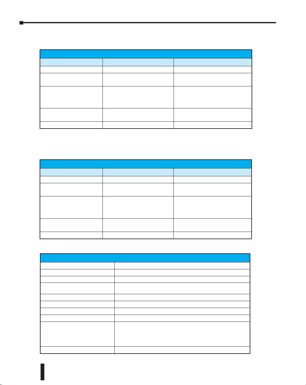
Chapter 4: Specifications - Terminal Bases and Power Supplies
T1K-08B(-1) I/O Terminal Base
Specifications
Specification T1K-08B T1K-08B-1
Terminal Type Screw type Spring clamp type
Recommended Torque
Recommended Screwdriver
Blade Size
Wire Gauge Size
Weight 135g 125g
1.77–3.54 lb·in
(0.2–0.4 N·m)
0.02 in. X 0.125 in.
(0.5 mm X 3.0 mm)
Solid conductor: 25–12 AWG
Stranded conductor: 26–12 AWG*
N/A
Push in on clamp using
screwdriver blade size:
0.016 X 0.79 in. to 0.032 X 0.16 in.
(0.4 mm X 2mm to 0.8 mm X 4mm)
Solid conductor: 25–14 AWG
Stranded conductor: 26–14 AWG*
*Twist stranded conductors before inserting into gate.
T1K-16B(-1) I/O Terminal Base
Specifications
Specification T1K-16B T1K-16B-1
Terminal Type Screw type Spring clamp type
Recommended Torque
Recommended Screwdriver
Blade Size
Wire Gauge Size
Weight 220g 210g
*Twist conductors before inserting into gate.
1.77–3.54 lb·in
(0.2–0.4 N·m)
0.02 in. X 0.125 in.
(0.5 mm X 3.0 mm)
Solid conductor: 25–12 AWG
Stranded conductor: 26–12 AWG*
N/A
Push in on clamp using
screwdriver blade size:
0.016 X 0.79 in. to 0.032 X 0.16 in.
(0.4 mm X 2mm to 0.8 mm X 4mm)
Solid conductor: 25–14 AWG
Stranded conductor: 26–14 AWG*
4–2
Environmental Specifications
Ambient Operating Temperature 32!F to 131!F (0!C to 55!C)
Storage Temperature -4!F to 158!F (-20!C to 70!C)
Ambient Humidity 5% to 95% (Non-condensing)
Atmosphere
Vibration Resistance MIL STD 810C. Method 514.2
Shock Resistance MIL STD 810C. Method 516.2
Voltage Withstand 1500VAC, 1 minute
Insulation Resistance 500VDC, 10Mq
Noise Immunity
Agency Approvals UL E185989, CE, FCC class A
No corrosive gases. The level of environmental pollution = 2
(UL 840).
NEMA ICS3-304
Impulse Noise 1es, 1000V
FCC class A
RFI (144MHz, 430MHz 10W, 10cm)
Do-more T1H Series PLC Hardware User Manual, 1st Edition, Rev. C
Page 61

T1K-08B, T1K-08B-1
Chapter 4: Specifications - Terminal Bases and Power Supplies
T1K-16B, T1K-16B-1
Do-more T1H Series PLC Hardware User Manual, 1st Edition, Rev. C
4–3
Page 62

Chapter 4: Specifications - Terminal Bases and Power Supplies
T1K-01AC, T1K-01DC Power Supply
Specifications
Specification T1K-01AC T1K-01DC
Input Voltage Range 110/220 VAC (85–264 VAC) 12/24 VDC (10.8–26.4 VDC)
Input Frequency 50/60 Hz (47–63 Hz) Maximum Power 50VA 20W
Maximum Inrush Current 20A 10A
Insulation Resistance >10Mq @ 500VDC
Voltage Withstand (Dielectric) 1 min. @ 1500VAC between primary, secondary and field ground
Auxiliary 24VDC Supply 300mA maximum Output 1:
5VDC
Base Power
Supplied
Output 2:
24VDC
Base Power
Supplied
Replacement Terminal Block Phoenix Contact
Fuse 1 (Primary) not replaceable
NOTE: 500mA @ 24VDC is achieved by lowering the 5VDC to 1.5 A from 2.0 A.
Voltage 5.25 VDC (5.00–5.50 VDC) 5.25 VDC (5.00– 5.50 VDC)
Current
Ripple 5% maximum 5% maximum
Voltage 24VDC (20.0–28.0 VDC) -
Current
Ripple 10% maximum -
a) 2.0 A maximum
b) 1.5 A maximum (see note)
a) 300mA maximum
b) 500mA maximum (see note)
MVSTBW 2.5/4-ST-5.08 BK MVSTBW 2.5/6-ST-5.08 BK
2.0 A maximum
-
4–4
Environmental Specifications
Ambient Operating Temperature 32!F to 131!F (0!C to 55!C)
Storage Temperature -4!F to 158!F (-20!C to 70!C)
Ambient Humidity 5% to 95% (Non-condensing)
Atmosphere
Vibration Resistance MIL STD 810C. Method 514.2
Shock Resistance MIL STD 810C. Method 514.2
Voltage Withstand 1500VAC, 1 minute
Insulation Resistance 500VDC, 10Mq
Noise Immunity
No corrosive gases. The level of
environmental pollution = 2 (UL 840).
NEMA ICS3-304
Impulse Noise 1es, 1000V
FCC class A
RFI (144MHz, 430MHz 10W, 10cm)
Do-more T1H Series PLC Hardware User Manual, 1st Edition, Rev. C
Page 63

e
12.0-24.0V
20W
+
_
Chapter 4: Specifications - Terminal Bases and Power Supplies
100-240V
50-60Hz 50VA
AC(L)
AC(N)
+
24V
OUT
LG
G
_
LG
G
T1K-01DC
1 PULL TO UNLOCK
Power Supply #1
Power Supply #1
Power Supply #2
Power Supply #2
T1K-01AC
1 PULL TO UNLOCK
T1K-01ACT1K-01DC
T1K-10CBL Base Expansion Cabl
T1K-10CBL Base Expansion Cable
Note: Use the T1K–01AC 24VDC auxiliary supply or an external user
supply for modules that require an external 24VDC.
Important Power Budget Note: For each power supply in a system
make sure the current required by the CPU and I/O modules does
not exceed the current supplied at both 5VDC and 24VDC (if using
the 24VDC auxiliary supply).
Do-more T1H Series PLC Hardware User Manual, 1st Edition, Rev. C
4–5
Page 64
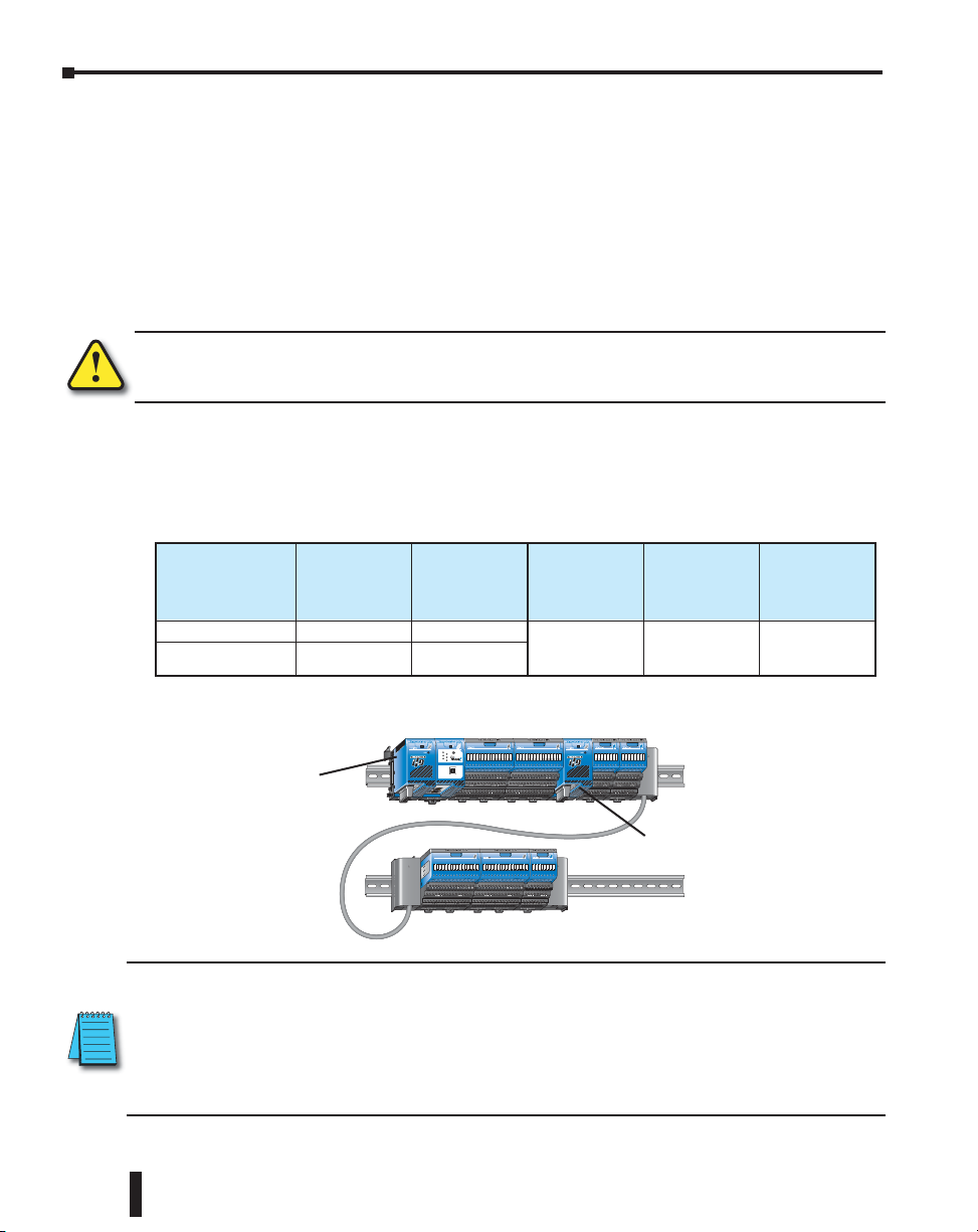
Chapter 4: Specifications - Terminal Bases and Power Supplies
Calculating the Power Budget
Managing the Power Resource
When determining the types and quantity of I/O modules to be used in the Do-more T1H
Series PLC system, it is important to remember there is a limited amount of power available
from the power supply. A chart is provided to help you easily see the amount of power
available with AC and DC power supplies. At the end of this section you will also find an
example of power budgeting and a worksheet showing sample calculations.
If the chosen I/O exceeds the maximum power available from the power supply the problem
is corrected by simply adding another power supply .
WARNING: It is extremely important to calculate the power budget correctly. If you exceed the power
budget, the system may operate in an unpredictable manner which may result in a risk of personal
injury or equipment damage.
Power Supply Specifications
The following chart shows the amount of current supplied by the Terminator I/O power
supply. Use this to calculate the power budget for your system. The Auxiliary 24V Power
Source mentioned in the table can be used to power field devices or modules that require an
external 24VDC.
AC Power
Supply
5VDC Current
Supplied in mA
(Internal)
T1K-01AC 2000 300
T1K-01AC (see Note) 1500 500
Auxiliary
24VDC Power
Source Current
Supplied in mA
DC Power
Supply
T1K-01DC 2000 -
5VDC Current
Supplied in mA
(Internal)
Auxiliary
24VDC Power
Source Current
Supplied in mA
4–6
Note A max. of 500mA @ 24VDC can be achieved by lowering the 5VDC to 1500mA.
T1H-DM1E
TERM
RUN
RUN STOP
USB
I/O
TX
ERR
RX
USB
PGM
Power Supply #1
PORT
Power Supply #2
NOTE: Important about Power Supplies - One power supply is required in the leftmost component position (Power
Supply #1), as shown above. Additional power supplies should be added between I/O modules as necessary to
meet power budget requirements. Each power supply powers the modules to its right, but is interrupted by the
next power supply. It is not mandatory to have a power supply in the leftmost position on an expansion rack.
The system shown above: Power Supply #1 powers the CPU module and the two I/O modules to its right.
Power Supply #2 powers the remaining five I/O modules. This is only an example and the power budget
requirements vary depending on the I/O modules used.
Do-more T1H Series PLC Hardware User Manual, 1st Edition, Rev. C
Page 65

Chapter 4: Specifications - Terminal Bases and Power Supplies
Module Power Requirements
This chart shows the amount of maximum current required for each of the Do-more T1H
PLC modules. Use this information to calculate the power budget for your system. If an
external 24VDC power source is required, you can use the built-in 24VDC auxiliary supply
as long as you do not exceed the power budget. If any device is connected to the Controller’s
serial port that uses the 5VDC supply pin, be sure to include the device’s power consumption
in your 5VDC power budget calculation.
Terminator Module Power Consumption
Module 5VDC (mA) 24VDC (mA) Module 5VDC (mA) 24VDC (mA)
CPU Modules Analog Input Modules
T1H-DM1 250 0 T1F-08AD-1 75 50 (see note 1)
T1H-DM1E 275 0 T1F-16AD-1 75 50 (see note 1)
DC Input Modules
T1K-08ND3 35 0 T1F-16AD-2 75 50 (see note 1)
T1K-16ND3 70 0 T1F-16RTD 150 0
- - - T1F-16TMST 150 0
AC Input Modules
T1K-08NA-1 35 0
T1K-16NA-1 70 0 T1F-08DA-1 75 150 (see note 1)
DC Output Modules
T1K-08TD1 100 200 (see note 1)
T1K-08TD2-1 100 0
T1H-08TDS 200 0
T1K-16TD1 200 400 (see note 1)
T1K-16TD2-1 200 0
AC Output Modules Combination Analog Modules
T1K-08TA 250 0
T1K-16TA 450 0
T1K-08TAS 300 0
Relay Output Modules
T1K-08TR 350 0
T1K-16TR 700 0
T1K-08TRS 400 0
T1F-08AD-2 75 50 (see note 1)
T1F-14THM 60 70 (see note 1)
Analog Output Modules
T1F-16DA-1 75 150 (see note 1)
T1F-08DA-2 75 150 (see note 1)
T1F-16DA-2 75 150 (see note 1)
T1F-8AD4DA-1 75
T1F-8AD4DA-2 75 70 (see note 1)
60 (see note 1
and 2)
Specialty Module and other devices
T1H- CTRIO 400 0
Note 1: Use T1K-01AC 24VDC auxiliary supply or external user supply.
Note 2: 60mA plus 20mA per output loop.
NOTE: Important Power Budget - For each power supply in a system, make sure the current required by the CPU
module and I/O modules does not exceed the current supplied at both 5VDC and 24VDC.
Do-more T1H Series PLC Hardware User Manual, 1st Edition, Rev. C
4–7
Page 66
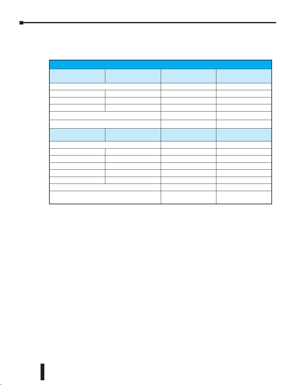
Chapter 4: Specifications - Terminal Bases and Power Supplies
Power Budget Calculation Example
The following example shows how to calculate the power budget for a Do-more T1H Series
PLC system.
PLC
Power Supply #1 Part Number
Power Supplied T1K-01AC 2000 300
CPU T1H-DM1E 275 0
Module T1K-16NA-1 70 0
Module T1K-16TA 450 0
Maximum power required 795 0
Remaining power available 2000-795 = 1205 300-0 = 300
Power Supply #2 Part Number
Power Supplied T1K-01AC 1500 500
Module T1K-08AD-2 75 50
Module T1K-08AD-2 75 50
Module T1K-16TD1 200 400
Module T1K-08TR 350 0
Module T1K-08ND3 35 0
Maximum power required 735 500
Remaining power available 1500-735 = 765
5VDC (mA)
Required
5VDC (mA)
Required
24VDC (mA)
Required
24VDC (mA)
Required
500-500 = 0
(see note 1)
4–8
Note 1: An external user power supply must be used if the 24VDC current requirement exceeds the T1K-01AC
24VDC auxiliary supply.
1. Fill in the information for the CPU, I/O modules, and any other devices that will use
system power, including devices that use the 24VDC output. Devices which fall into
the “Other” category are devices such as an operator interface which also has power
requirements but do attach as a module to the system.
2. Add the current columns starting with the CPU and put the total in the row labeled
“Maximum power required”.
3. Subtract the row labeled “Maximum power required” from the “Power Supplied”. Place
the difference in the row labeled “Remaining Power Available”.
4. If “Maximum Power Required” is greater than “Power Supplied” in either of the two
columns, the power budget will be exceeded. It will be unsafe to use this configuration
and you will need to restructure your configuration.
Do-more T1H Series PLC Hardware User Manual, 1st Edition, Rev. C
Page 67

Chapter
Chapter
SpecificationS -
Chapter
DiScrete i/o MoDuleS
5
5
1
In This Chapter:
Discrete I/O Modules Overview ���������������������������������������������������������������������������������� 5–2
Discrete Input Modules ���������������������������������������������������������������������������������������������� 5–2
Discrete Output Modules ������������������������������������������������������������������������������������������� 5–2
T1K-08ND3 - DC Input ������������������������������������������������������������������������������������������������ 5–3
T1K-16ND3 - DC Input ������������������������������������������������������������������������������������������������ 5–5
T1K-08NA-1 - AC Input ������������������������������������������������������������������������������������������������ 5–7
T1K-16NA-1 - AC Input ������������������������������������������������������������������������������������������������ 5–8
T1K-08TD1 - DC Output ���������������������������������������������������������������������������������������������� 5–9
T1K-16TD1 - DC Output �������������������������������������������������������������������������������������������� 5–10
T1K-08TD2-1 - DC Output ����������������������������������������������������������������������������������������� 5–11
T1K-16TD2-1 - DC Output ����������������������������������������������������������������������������������������� 5–12
T1H-08TDS - Isolated DC Output ������������������������������������������������������������������������������ 5–13
T1K-08TA - AC Output ����������������������������������������������������������������������������������������������� 5–14
T1K-16TA - AC Output ����������������������������������������������������������������������������������������������� 5–15
T1K-08TAS - Isolated AC Output ������������������������������������������������������������������������������� 5–16
T1K-08TR - Relay Output ������������������������������������������������������������������������������������������� 5–17
T1K-16TR - Relay Output ������������������������������������������������������������������������������������������� 5–18
T1K-08TRS - Isolated Relay Output ��������������������������������������������������������������������������� 5–19
Page 68

Chapter 5: Specifications - Discrete I/O Modules
Discrete I/O Modules Overview
There are 15 discrete I/O modules available. The specifications and wiring diagrams for these
modules are found in this chapter. Each discrete I/O module is identified as an “Input” or
“Output” module using the color coding scheme shown below. A blue dot on the front panel
signifies an Input module and a red dot signifies an Output module.
Discrete Input Modules
Module
Part Number
T1K-08ND3
0 1 2 3 4 5 6 7
0 1 2 3 4 5 6 7
Module Type
(Blue: Input)
Part Number
T1K-08ND3
T1K-16ND3
T1K-08NA-1
T1K-16NA-1
Discrete Input Modules
Number of
Inputs
8 Sinking/Sourcing DC Input 5-4
16 Sinking/Sourcing DC Input 5-6
8 AC Input 5-8
16 AC Input 5-9
Description See Page
Discrete Output Modules
Module
Part Number
5–2
T1K-08TD1
FU1
24V
FU2
0 1 2 3 4 5 6 7
0 1 2 3 4 5 6 7
WARNING: The T1H Series PLC does not support any Hot-Swap features.
Do-more T1H Series PLC Hardware User Manual, 1st Edition, Rev. C
Module Type
(Red: Output)
Part Number
T1K-08TD1
T1K-16TD1
T1K-08TD2-1
T1K-16TD2-1
T1H-08TDS
T1K-08TA
T1K-16TA
T1K-08TAS
T1K-08TR
T1K-16TR
T1K-08TRS
Discrete Output Modules
Number of
Outputs
8 Sinking DC Output 5-10
16 Sinking DC Output 5-11
8 Sourcing DC Output 5-12
16 Sourcing DC Output 5-13
8 Isolated Sinking/Sourcing DC Output 5-14
8 AC Output 5-15
16 AC Output 5-16
8 Isolated AC Output 5-17
8 Relay Output 5-18
16 Relay Output 5-19
8 Isolated Relay Output 5-20
Description See Page
Page 69

T1K-08ND3 - DC Input
Ambient Temperature (
°C/°F)
Derating Chart
Input points
Note
Externa
Sink Module
Configuration
Shown
V 1
Specifications
Inputs Per Module
Commons Per Module
Operating Voltage
Input Voltage Range
Peak Voltage
Input Current (Typical)
Input Impedance
ON Voltage Level
OFF Voltage Level
Min. ON Current
Max. OFF Current
OFF to ON Response
ON to OFF Response
Base Power Requirements
Status Indicators
Weight
8 (sink / source)
Ext. power: 2, isolated (4 pts. / com.)
Int. power: 2, all 8 pts. internally connected
12–24 VDC
10.8–26.4 VDC min. / max.
30VDC
4mA @ 12VDC, 8.5 mA @ 24VDC
2.8 kq
> 10.0 VDC
< 2.0 VDC
4mA
0.5 mA
2–8 ms, Typical: 4ms
2–8 ms, Typical: 4ms
35mA @ 5VDC
Logic Side
70g
Chapter 5: Specifications - Discrete I/O Modules
T1K-08ND3
0 1 2 3 4 5 6 7
0 1 2 3 4 5 6 7
Points
8
6
4
2
0
032105020683086 40
104
50 55
122 131
:
l Power,
°C
°F
V 0 and V 1 supply 24 VDC
or 0 VDC if Internal Power
Jumper is selected
Commons
V 0
Top
Row
Bottom
Row
Do-more T1H Series PLC Hardware User Manual, 1st Edition, Rev. C
5–3
Page 70
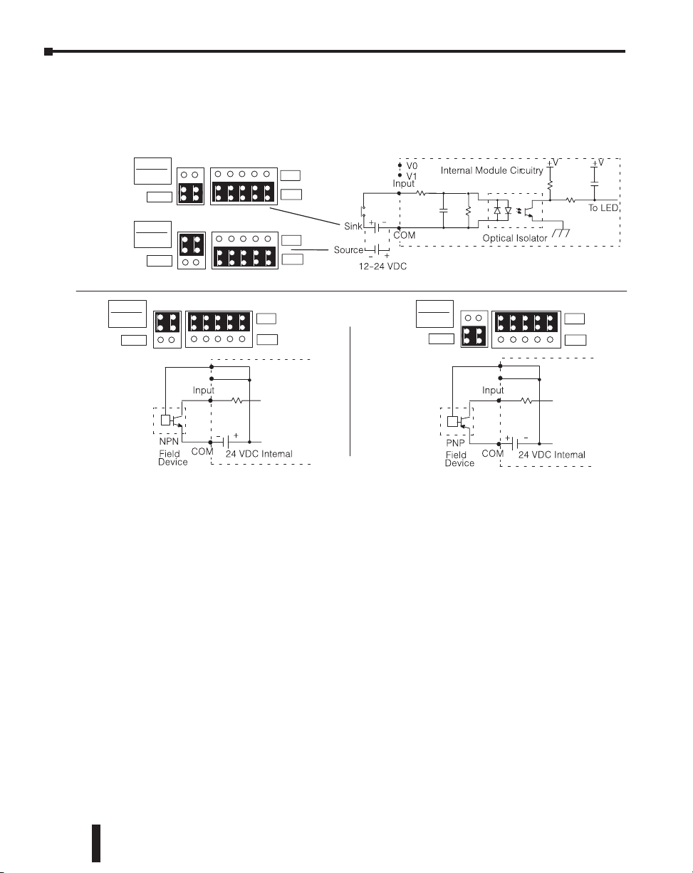
Chapter 5: Specifications - Discrete I/O Modules
Jumper Selection
External Power
Sink Module
External Power
MODULE
SOURCE
SINK
INT
EXT
Equivalent Input Circuit
Source Module
External Power
Source Module
Internal Power
MODULE
SOURCE
SINK
MODULE
SOURCE
SINK
V 0
V 1
INT
EXT
INT
EXT
Internal Module
Circuitry
Internal Power
Sink Module
Internal Power
MODULE
SOURCE
SINK
V 0
V 1
INT
EXT
Internal
Module
Circuitry
5–4
Do-more T1H Series PLC Hardware User Manual, 1st Edition, Rev. C
Page 71

T1K-16ND3 - DC Input
° C/ ° F)
Derating Chart
Input points
Jumper is selected
Specifications
Inputs Per Module
Commons Per Module
Operating Voltage
Input Voltage Range
Peak Voltage
Input Current (Typical)
Input Impedance
ON Voltage Level
OFF Voltage Level
Min. ON Current
Max. OFF Current
OFF to ON Response
ON to OFF Response
Base Power Requirements
Status Indicators
Weight
16 (sink / source)
Ext. power: 4, isolated (4 pts. / com.)
Int. power: 4, all 16 pts. internally connected
12–24 VDC
10.8 - 26.4 VDC min. / max.
30VDC
4mA @ 12VDC, 8.5 mA @ 24VDC
2.8 kq
>10.0 VDC
<2.0 VDC
4mA
0.5 mA
2–8 ms, Typical: 4ms
2–8 ms, Typical: 4ms
70mA @ 5VDC
Logic Side
160g
Chapter 5: Specifications - Discrete I/O Modules
T1K-16ND3
0 1 2 3 4 5 6 7 8 9 10 11 12 13 14 15
0 1 2 3 4 5 6 7 8 9 10 11 12 13 14 15
Top
8910 11 12 13 1415 01 234567
Row
Points
16
12
8
4
0
0
10
20
30
32
50
Ambient Te mperature (
68
86
40
104
50 55
122 131
° C
° F
12-24 VDC
COM 0COM 1COM 2COM 3
Commons
V 0V 1
V 0–V 3 supply 24 VDC or
0 VDC if Internal Power
NOTE: When using external power, the module can be wired to either sink current or source current
regardless of the module’s sink/source jumper position. When using internal power, the sink/source jumpers
determine the module’s configuration.”
Do-more T1H Series PLC Hardware User Manual, 1st Edition, Rev. C
V 2V 3
12-24 VDC
Bottom
Row
5–5
Page 72

Chapter 5: Specifications - Discrete I/O Modules
Source Modul
Internal Power
Jumper Selection
External Power
Sink Module
MODULE
SOURCE
SINK
MODULE
SOURCE
SINK
External Power
INT
EXT
Source Module
External Power
INT
EXT
Equivalent Input Circuit
MODULE
SOURCE
SINK
Internal Power
INT
EXT
V 0-V 3
e
Internal Module
Circuitry
Field
Device
Sink Module
Internal Power
MODULE
SOURCE
SINK
V 0-V 3
Field
Device
Internal Module
Circuitry
INT
EXT
5–6
Do-more T1H Series PLC Hardware User Manual, 1st Edition, Rev. C
Page 73

T1K-08NA-1 - AC Input
V 0, V 1 not used with AC Input Modules
Input points
Commons
T1K–08NA–1
123456 70
12345670
48 (1.89)
)51.3( 08
)41.2(3.45
)10.1(7.52
9.2 (0.36)
8.1 (0.32)
8.1 (0.32)
83.3 (3.28)
Side View
mm (in.)
COM 0 COM 1
V 0V 1
90-120 VAC
Input points
Commons
T1K–08NA–1
12345670
12345670
48 (1.89)
)51.3( 08
)41.2(3.45
)10.1(7.52
9.2 (0.36)
8.1 (0.32)
8.1 (0.32)
83.3 (3.28)
Side View
mm (in.)
0
2
4
6
8
Ambient Temperature (
°C/°F)
Derating Chart
Points
032105020683086 40
104
50 55
122 131
°C
°F
COM 0 COM 1
V 0V 1
90-120 VAC
Input points
90-120 V
AC
Inputs Per Module
Commons Per Module
Operating Voltage
Input Voltage Range
Input Current
Input Impedance
ON Current / Voltage
OFF Current / Voltage
OFF to ON Response
ON to OFF Response
Base Power Requirements
Status Indicators
Weight
Points
8
6
4
2
0
032105020683086 40
Ambient Te mperature (
Specifications
Derating Chart
90-120 VAC
Chapter 5: Specifications - Discrete I/O Modules
8
2, 4 pts. / com. (Isolated)
90–120 VAC, 47–63 Hz
80–132 VAC, 47–63 Hz min. / max.
8mA @ 100VAC (50Hz)
10mA @ 100VAC (60Hz)
12mA @ 132VAC (50Hz)
15mA @ 132VAC (60Hz)
14kV @ 50Hz, 12kV @ 60Hz
> 6mA @ 75VAC
< 2.0 mA @ 20VAC
< 40ms
< 40ms
35mA @ 5VDC
Logic Side
70g
50 55
104
122 131
°C/°F)
Input
COM
°C
°F
Equivalent Input Circuit
Internal Module Circuitry
AC
Optical Isolator
T1K-08NA-1
0 1 2 3 4 5 6 7
0 1 2 3 4 5 6 7
COM 0 COM 1
Commons
V 0 V 1
V 0, V 1 not used with AC Input Modules
+V +V
To LED
Top
Row
90-120 V
Bottom
Row
Do-more T1H Series PLC Hardware User Manual, 1st Edition, Rev. C
5–7
Page 74

Chapter 5: Specifications - Discrete I/O Modules
mm (in.)
NA–1
) 5 1 . 3 ( 0 8
) 4 1 . 2 ( 3 . 4 5
) 1 0 . 1 ( 7 . 5 2
9.2 (0.36)
8.1 (0.32)
8.1 (0.32)
89 (3.5)
Input points
Commons
8910 11 12 13 1415 01 234567
83.3 (3.28)
Side View
V 0V 1
V 2V 3
90-120 VAC
mm (in.)
NA–1
) 5 1 . 3 ( 0 8
) 4 1 . 2 ( 3 . 4 5
) 1 0 . 1 ( 7 . 5 2
9.2 (0.36)
8.1 (0.32)
8.1 (0.32)
89 (3.5)
V 0–V 3 not used with AC Input Modules
Input points
Commons
8910 111213 1415 01 234567
COM 0COM 1COM 2COM 3
83.3 (3.28)
Side View
V 0V 1
V 2V 3
0
4
8
12
16
Ambient Temperature (
° C/ ° F)
Derating Chart
Points
0
32
10
50
20
68
30
86
40
104
50 55
122 131
° C
° F
90-120 VAC
90-120 VAC
V 0–V 3 not used with AC Input Modules
Input points
90-120 V
AC
T1K-16NA-1 - AC Input
Specifications
Inputs Per Module
Commons Per Module
Operating Voltage
Input Voltage Range
Input Current
Input Impedance
ON Current / Voltage
OFF Current / Voltage
OFF to ON Response
ON to OFF Response
Base Power Requirements
Status Indicators
Weight
16
4, 4 pts. / com. (Isolated)
90–120 VAC, 47–63 Hz
80–132 VAC, 47–63 Hz min. / max.
8mA @ 100VAC (50Hz)
10mA @ 100VAC (60Hz)
12mA @ 132VAC (50Hz)
15mA @ 132VAC (60Hz)
14kV @ 50Hz, 12kV @ 60Hz
> 6mA @ 75VAC
< 2.0 mA @ 20VAC
< 40ms
< 40ms
70mA @ 5VDC
Logic Side
120g
T1K-16NA-1
0 1 2 3 4 5 6 7 8 9 10 11 12 13 14 15
Points
12
16
8
4
0
0
10
32
50
Ambient Temperature (
Derating Chart
20
30
68
86
90-120 VAC
40
104
Input
° C/ ° F)
COM
° C
50 55
122 131
° F
COM 0COM 1COM 2COM 3
AC
V 0V 1
Equivalent Input Circuit
Internal Module Circuitry
Optical Isolator
Commons
+V
8910 11 12 13 1415 01 234567
V 2V 3
+V
To LED
Top
Row
90-120 V
Bottom
Row
5–8
Do-more T1H Series PLC Hardware User Manual, 1st Edition, Rev. C
Page 75

T1K-08TD1 - DC Output
1234567 0
1234567 0
48 (1.89)
) 5 1 . 3 ( 0 8
) 4 1 . 2 ( 3 . 4 5
) 1 0 . 1 ( 7 . 5 2
9.2 (0.36)
8.1 (0.32)
mm (in.)
8.1 (0.32)
Output Points
Commons
Fuses located
under top cover
83.3 (3.28)
T1K–08TD1
V 0–V 1 internally connected
T1K–08TD1
Derating Chart
0 1 2 3 4 5 6 7
COM 0 COM 1 12-24 VDC
V 0 V 1
1234567 0
1234567 0
48 (1.89)
) 5 1 . 3 ( 0 8
) 4 1 . 2 ( 3 . 4 5
) 1 0 . 1 ( 7 . 5 2
9.2 (0.36)
8.1 (0.32)
mm (in.)
8.1 (0.32)
Output Points
Commons
Fuses located
under top cover
83.3 (3.28)
Side View
T1K–08TD1
V 0–V 1 internally connected
T1K–08TD1
Ambient Temperature (
° C/ ° F)
Derating Chart
0
32
10
50
20
68
30
86
40
104
50 55
122 131
° C
° F
0 1 2 3 4 5 6 7
COM 0 COM 1 12-24 VDC
24 VDC
V 0 V 1
0
2
4
6
8
Points
0.5A
1.0A
0.75A
Specifications
Outputs Per Module
Commons Per Module
Operating Voltage Range
Output Voltage Range
Peak Voltage
Max. Load Current
Max. Leakage Current
ON Voltage Drop
Max. Inrush Current
OFF to ON Response
ON to OFF Response
Base Power Requirements
External Power Required
Status Indicators
Error Status Indicators
(LEDs)
Fuses (User Replaceable)
T1K-FUSE-1
Weight
Points
8
6
4
2
0
0
32
10
50
Ambient Te mperature (
6-27 VDC
8 (sink)
2 internally connected
6–27 VDC
5–30 VDC min. / max.
50VDC
1A / pt., 4A / common
15eA @ 30VDC
0.3 VDC @ 1.0 A
2A for 100ms
< 10es
< 60es
100mA @ 5VDC
200mA max. @ 20–28 VDC
Logic Side
24V ON = low external power
FU1 / FU2 ON = fuse 1 or fuse 2 blown
2, (6.3 A, 250V / common), (4 pts. / fuse)
NQ3 - 6.3 SOC corp.
85g
20
30
68
86
24 VDC
Output
L
40
50 55
104
122 131
° C/ ° F)
V 0
V 1
Chapter 5: Specifications - Discrete I/O Modules
T1K-08TD1
FU1
24V
FU2
0 1 2 3 4 5 6 7
0 1 2 3 4 5 6 7
24 VDC
Optical Isolator
Output Points
0 1 2 3 4 5 6 7
COM 0 COM 1 12-24 VDC
Commons
V 0 V 1
V 0–V 1 internally connected
To LED
0.5A
0.75A
1.0A
° C
° F
Equivalent Output Circuit
Internal Module Circuitry
Top
Row
Bottom
Row
6.3 A
COM
Other Circuits
Do-more T1H Series PLC Hardware User Manual, 1st Edition, Rev. C
5–9
Page 76
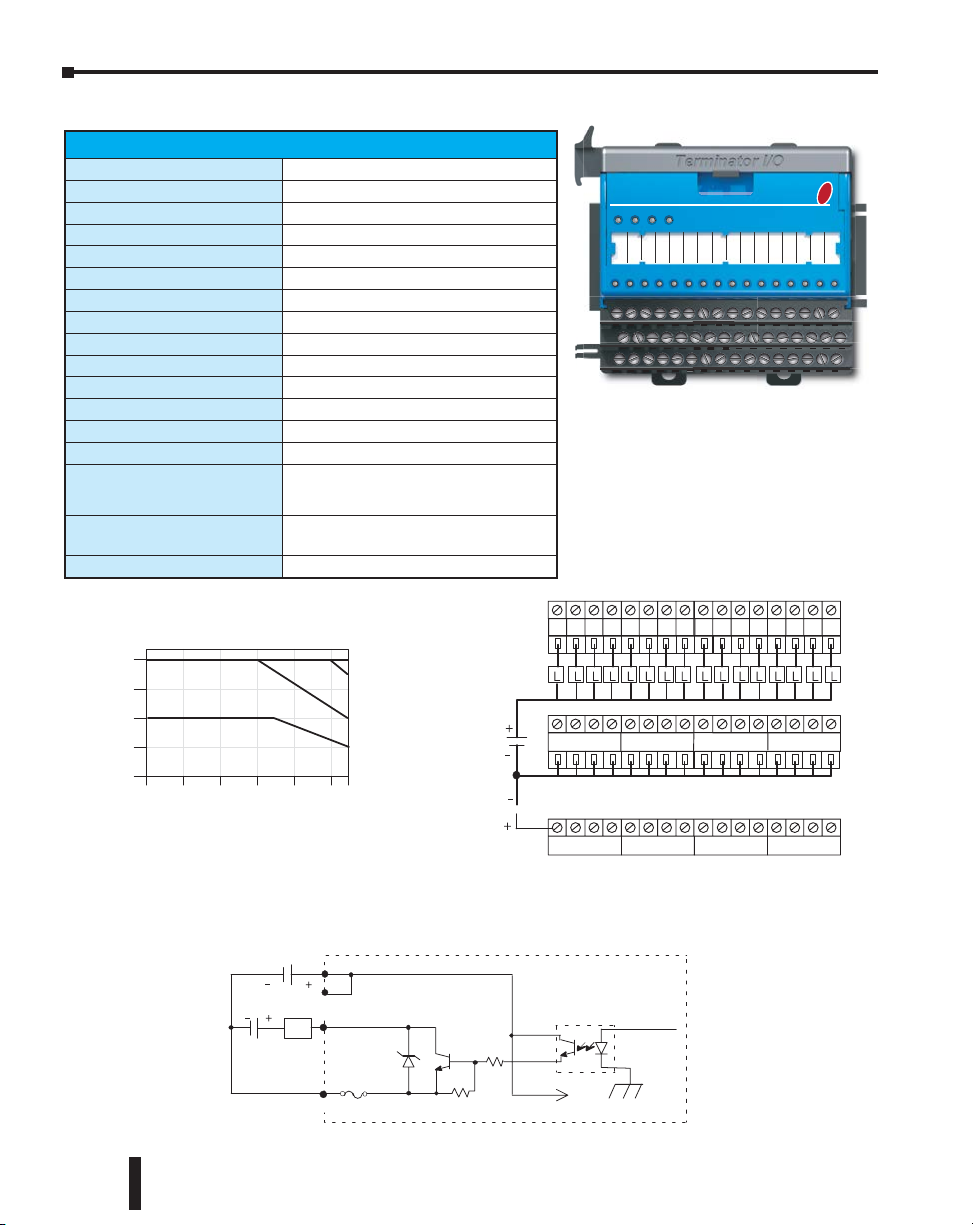
Chapter 5: Specifications - Discrete I/O Modules
mm (in.)
Output Points
Commons
8910 11 1213 1415 01 234567
TD1
) 5 1 . 3 ( 0 8
) 4 1 . 2 ( 3 . 4 5
) 1 0 . 1 ( 7 . 5 2
9.2 (0.36)
8.1 (0.32)
8.1 (0.32)
89 (3.5)
Fuses located
under top cover
COM 0COM 1COM 2COM 3
83.3 (3.28)
Side View
V 0 V 1 V 2 V 3
V 0 – V 3 internally connected
Derating Chart
T1K–16TD1
mm (in.)
Output Points
Commons
891011 1213 14 15 01 234567
TD1
) 5 1 . 3 ( 0 8
) 4 1 . 2 ( 3 . 4 5
) 1 0 . 1 ( 7 . 5 2
9.2 (0.36)
8.1 (0.32)
8.1 (0.32)
89 (3.5)
Fuses located
under top cover
COM 0COM 1COM 2COM 3
83.3 (3.28)
Side View
V 0 V 1 V 2 V 3
V 0 – V 3 internally connected
Derating Chart
0
4
8
12
16
Points
1.0A
T1K–16TD1
0.75A
0.5A
0.4A
Ambient Temperature (
° C/ ° F)
0
32
10
50
20
68
30
86
40
104
50 55
122 131
° C
° F
T1K-16TD1 - DC Output
Outputs Per Module
Commons Per Module
Operating Voltage Range
Output Voltage Range
Peak Voltage
Max. Load Current
Max. Leakage Current
ON Voltage Drop
Max. Inrush Current
OFF to ON Response
ON to OFF Response
Base Power Requirements
External Power Required
Status Indicators
Error Status Indicators
(LEDs)
Fuses (User Replaceable)
T1K-FUSE-1
Weight
Points
16
12
8
4
0
0
10
32
50
Ambient Te mperature (
20
68
30
86
6-27 VDC
Specifications
16 (sink)
4 internally connected
6–27 VDC
5–30 VDC min. / max.
50VDC
1A / pt., 4A / common
15eA @ 30VDC
0.3 VDC @ 1.0 A
2A for 100ms
< 10es
< 60es
200mA @ 5VDC
400mA max. @ 20–28 VDC
Logic Side
24V ON = low external power
FU1 / FU2 ON = fuse 1 or 2 blown
FU3 / FU4 ON = fuse 3 or 4 blown
4, (6.3 A, 250V / common), (4 pts. / fuse)
NQ3 - 6.3 SOC corp.
140g
0.4A
0.5A
0.75A
1.0A
50 55
122 131
Output
° C
° F
V0-V3
40
104
° C/ ° F)
24 VDC
L
12-24 VDC
Equivalent Output Circuit
Internal Module Circuitry
24 VDC
T1K-16TD1
FU1
24V FU3
FU2
FU4
0 1 2 3 4 5 6 7 8 9 10 11 12 13 14 15
0 1 2 3 4 5 6 7 8 9 10 11 12 13 14 15
Output Points
8910 11 1213 1415 01 234567
COM 0COM 1COM 2COM 3
Commons
V 0 V 1 V 2 V 3
V 0 – V 3 internally connected
Optical Isolator
To LED
Top
Row
Bottom
Row
5–10
6.3 A
COM
Do-more T1H Series PLC Hardware User Manual, 1st Edition, Rev. C
Other Circuits
Page 77

T1K-08TD2-1 - DC Output
12345670
12345670
48 (1.89)
)51.3( 08
)41.2(3.45
)10.1(7.52
9.2 (0.36)
8.1 (0.32)
mm (in.)
8.1 (0.32)
Output Points
Commons
Fuses located
under top cover
83.3 (3.28)
Side View
T1K–08TD2–1
V 0–V 1 internally connected
12-24 VDC
0 V 0 V
COM 0 COM 1
0 1 2 3 4 5 6 7
12345670
12345670
48 (1.89)
)51.3( 08
)41.2(3.45
)10.1(7.52
9.2 (0.36)
8.1 (0.32)
mm (in.)
8.1 (0.32)
Output Points
Commons
Derating Chart
0.75A
Fuses located
under top cover
83.3 (3.28)
Side View
T1K–08TD2–1
V 0–V 1 internally connected
1.0A
Ambient Temperature (
°C/°F)
105020683086 40
104
50 55
122 131
°C
°F
12-24 VDC
12-24 VDC
0 V 0 V
COM 0 COM 1
0 1 2 3 4 5 6 7
Output Points
Outputs Per Module
Commons Per Module
Operating Voltage Range
Output Voltage Range
Peak Voltage
Max. Load Current
Max. Leakage Current
ON Voltage Drop
Max. Inrush Current
OFF to ON Response
ON to OFF Response
Base Power Requirements
Status Indicators
Error Status Indicators
(LEDS)
Fuses (User Replaceable)
T1K-FUSE-1
Weight
Points
8
6
4
2
0
Specifications
8 (source)
2 internally connected
12–24 VDC
10.8 - 26.4 VDC min. / max.
50VDC
1A / pt., 4A / common
15eA @ 26.4 VDC
1.2 VDC @ 1.0 A
2A for 100ms
< 10es
< 0.5 ms
100mA @ 5VDC
Logic Side
FU1 / FU2 ON = fuse 1 or fuse 2 blown
2, (6.3 A, 250V / common), (4 pts. / fuse)
Derating Chart
032105020683086 40
Ambient Te mperature (
NQ3 - 6.3 SOC corp.
100g
50 55
104
122 131
°C/°F)
0.75A
1.0A
°C
°F
Chapter 5: Specifications - Discrete I/O Modules
T1K-08TD2-1
FU1
FU2
0 1 2 3 4 5 6 7
12-24 VDC
Note: Apply the 0 V label that comes with the I/O
module to I/O base terminal points V 0–V 1 to
properly identify the 0 VDC terminal points.
0 1 2 3 4 5 6 7
0 1 2 3 4 5 6 7
COM 0 COM 1
Commons
0 V 0 V
V 0–V 1 internally connected
Top
Row
12-24 VDC
Bottom Row
Equivalent Output Circuit
Output
0 V
(V 0 - V 1)
Internal Module Circuitry
Optical Isolator
L
6.3 A
COM
Do-more T1H Series PLC Hardware User Manual, 1st Edition, Rev. C
Other Circuits
To LED
5–11
Page 78

Chapter 5: Specifications - Discrete I/O Modules
mm (in.)
Output Points
Commons
V 0 – V 3 internally connected
8910 11 1213 141501 234567
TD2–1
)51.3( 08
)41.2(3.45
)10.1(7.52
9.2 (0.36)
8.1 (0.32)
8.1 (0.32)
89 (3.5)
Fuses located
under top cover
COM 0COM 1COM 2COM 3
83.3 (3.28)
Side View
0 V0 V
0 V0 V
12-24 VDC
mm (in.)
8910 11 1213 141501 234567
TD2–1
)51.3( 08
)41.2(3.45
)10.1(7.52
9.2 (0.36)
8.1 (0.32)
8.1 (0.32)
89 (3.5)
0.5A
Fuses located
under top cover
83.3 (3.28)
Side View
0 V0 V
1.0A
0.75A
°C/°F)
3086 40
104
50 55
122 131
°C
°F
12-24 VDC
12-24 VDC
Output Points
12-24 VDC
T1K-16TD2-1 - DC Output
Specifications
Outputs Per Module
Commons Per Module
Operating Voltage Range
Output Voltage Range
Peak Voltage
Max. Load Current
Max. Leakage Current
ON Voltage Drop
Max. Inrush Current
OFF to ON Response
ON to OFF Response
Base Power Requirements
Status Indicators
Error Status Indicators
(LEDs)
Fuses (User Replaceable)
T1K-FUSE-1
Weight
Points
16
12
8
4
0
Derating Chart
032105020683086 40
Ambient Te mperature (
16 (source)
4 internally connected
12–24 VDC
10.8–26.4 VDC min. / max.
50VDC
1A / pt., 4A / common (Subject to derating)
15eA @ 26.4 VDC
1.2 VDC @ 1.0 A
2A for 100ms
<10es
< 0.5 ms
200mA @ 5VDC
Logic Side
FU1 / FU2 ON = fuse 1 or 2 blown
FU3 / FU4 ON = fuse 3 or 4 blown
4, (6.3 A, 250 V / common), (4 pts. / fuse)
NQ3 - 6.3 SOC corp.
140g
104
°C/°F)
0.75A
50 55
122 131
0.5A
1.0A
°C
°F
T1K-16TD2-1
FU1
FU3
FU2
FU4
0 1 2 3 4 5 6 7 8 9 10 11 12 13 14 15
0 1 2 3 4 5 6 7 8 9 10 11 12 13 14 15
Top
12-24 VDC
8910 11 1213 1415 01 234567
COM 0COM 1COM 2COM 3
Commons
Row
Bottom
0 V0 V
V 0 – V 3 internally connected
0 V0 V
Row
Note: Apply the 0 V label that comes with the I / O
module to I / O base terminal points V 0–V 3 to
properly identify the 0 VDC terminal points.
5–12
Output
0 V
(V 0-V 3)
L
6.3 A
COM
Equivalent Output Circuit
Internal Module Circuitry
Optical Isolator
Other Circuits
To LED
Do-more T1H Series PLC Hardware User Manual, 1st Edition, Rev. C
Page 79

T1H-08TDS - Isolated DC Output
mm (in.)
)51.3( 08
)41.2(3.45
)10.1(7.52
8.1 (0.32)
8.1 (0.32)
89 (3.5)
T1H–08TDS
83.3 (3.28)
Side View
3
mm (in.)
)51.3( 08
)41.2(3.45
)10.1(7.52
9.2 (0.36)
8.1 (0.32)
8.1 (0.32)
89 (3.5)
T1H–08TDS
83.3 (3.28)
C6
C7
C7
L
L
Sinking
Examples
Output Points
Note: Apply the labels that come with the I/O
module to the I/O base to properly identify the
terminal points.
Output Points
Commons
44
0
0
112233
–––– USER BUS 1 ––––
mm (in.)
)51.3( 08
)41.2(3.45
)10.1(7.52
9.2 (0.36)
8.1 (0.32)
8.1 (0.32)
89 (3.5)
T1H–08TDS
83.3 (3.28)
Side View
–––– USER BUS 2 ––––
C0
C0
C1 C1
C2 C2 C3C3C4 C4 C5 C5 C6C6C7
C7
5566 77
5–36VDC
Sourcing
L
L
L
L
5–36VDC
Sinking
Examples
Examples
Equivalent Output Circuit
Sourcing (High Side Switching)
Sinking (Low Side Switching)
L
3
5-36 VDC
COM
Out
Opto Isolator
To LED
Inernal Module Circuitry
No connection: The 8 User Bus 1 terminals are
bussed together. The 8 User Bus 2 terminals are
also bussed together.
Outputs Per Module
Commons Per Module
Operating Voltage Range
Max. Voltage
Output Clamp Voltage
Max. Load Current
Electronic Over Current
Protection
Max. Load Voltage
Max. Leakage Current
Max. ON State Voltage
Drop
Inrush Current
OFF to ON Response
ON to OFF Response
Base Power Requirements
Thermal Shutdown
Over Temperature Reset
Status Indicators
Weight
5-36 VDC
Equivalent Output Circuit
COM
L
Out
Chapter 5: Specifications - Discrete I/O Modules
Specifications
8 (sink / source)
8 (isolated)
5–36 VDC
36VDC
40VDC
2A / pt., 16A / module, 32!F to 140!F
(0!C to 60!C)
Output trips at 6A min., 12A max.
36VDC
75eA
0.3 VDC @ 2.0 A, 0.15 V @ 1A
5A for 20ms
< 3es
< 100es
200mA max.
Between T-junction = 302!F to 374!F
(150!C to 190!C)
Thermal shutdown temp. minus 5°F (15°C)
Logic Side
93.6 g
Inernal Module Circuitry
Opto Isolator
To LED
T1H-08TDS
0 1 2 3 4 5 6 7
0 1 2 3 4 5 6 7
0
0
112233
44
5–36VDC
L
L
C0
Sourcing
5–36VDC
Commons
C1 C1
C0
C2 C2 C3C3C4 C4 C5 C5 C6C6C7
Sinking
5566 77
L
Top
Row
L
C7
Sinking (Low Side Switching)
5-36 VDC
Do-more T1H Series PLC Hardware User Manual, 1st Edition, Rev. C
COM
L
Out
Inernal Module Circuitry
Opto Isolator
To LED
–––– USER BUS 1 ––––
No connection: The 8 User Bus 1 terminals are
bussed together. The 8 User Bus 2 terminals are
–––– USER BUS 2 ––––
also bussed together.
Note: Apply the labels that come with the I/O
module to the I/O base to properly identify the
terminal points.
5–13
Bottom
Row
Page 80

T1K-08TA - AC Output
T1K–08TA
1234567 0
1234567 0
48 (1.89)
) 5 1 . 3 ( 0 8
) 4 1 . 2 ( 3 . 4 5
) 1 0 . 1 ( 7 . 5 2
9.2 (0.36)
8.1 (0.32)
mm (in.)
8.1 (0.32)
Fuses located
under top cover
83.3 (3.28)
Derating Chart
0.75A
Date Code: 00Z and later
17-240 VAC
T1K–08TA
1234567 0
1234567 0
48 (1.89)
) 5 1 . 3 ( 0 8
) 4 1 . 2 ( 3 . 4 5
) 1 0 . 1 ( 7 . 5 2
9.2 (0.36)
8.1 (0.32)
mm (in.)
8.1 (0.32)
Output Points
Commons
V 0–V 1 not used with AC Output Modules
Derating Chart
0.5A
Fuses located
under top cover
83.3 (3.28)
Side View
0.75A
1.0A
0
2
4
6
8
Derating Chart
Points
0.5A
0.75A
1.0A
Date Code: 008
Date Code: 00Z and later
Ambient Temperature (
° C/ ° F)
10
50
20
68
30
86
40
104
50 55
122 131
° C
° F
Ambient Temperature (
° C/ ° F)
0
32
10
50
20
68
30
86
40
104
50 55
122 131
° C
° F
17-240 VAC
0 1 2 3 4 5 6 7
COM 0 COM 1
V 0 V 1
Output Points
17-240 V
AC
Outputs Per Module
Commons Per Module
Operating Voltage Range
Output Voltage Range
Max. Load Current
ON Voltage Drop
Max. Leakage Current
Max. Inrush Current
Min. Load
OFF to ON Response
ON to OFF Response
Base Power Requirements
Status Indicators
Error Status Indicators
(LEDs)
Fuses (User Replaceable)
T1K-FUSE-2
Weight
Chapter 5: Specifications - Discrete I/O Modules
Specifications
8
2, 4 pts. / common (Isolated)
17–240 VAC (47–63 Hz)
15–264 VAC (47–63 Hz) min. / max.
1A / pt., 4A / common (Subject to derating)
1.5 VAC @ > 50mA, 4.0 VAC @ < 50mA
Points
8
6
4
2
0
0
32
17-240 VAC
10
50
Ambient Temperature (
20
68
30
86
Output
COM
4mA @ 264VAC
10A for 10ms
10mA
< 1ms
< 1ms + 1/2 cycle
250mA @ 5 VDC
Logic Side
FU1 ON = fuse 1 blown
FU2 ON = fuse 2 blown
2, (10A, 250V / common), (4 pts. / fuse)
5 x 20 mm type
140g
40
50 55
104
122 131
° C/ ° F)
10 A
0.5A
1.0A
° C
° F
Equivalent Output Circuit
Internal Module Circuitry
AC
0 1 2 3 4 5 6 7
COM 0 COM 1
Commons
V 0 V 1
V 0–V 1 not used with AC Output Modules
+ V
Optical Isolator
T1K-08TA
FU2FU1
0 1 2 3 4 5 6 7
0 1 2 3 4 5 6 7
Top
Row
Bottom
Row
To LED
17-240 V
5–14
Do-more T1H Series PLC Hardware User Manual, 1st Edition, Rev. C
Page 81

T1K-16TA - AC Output
mm (in.)
Output Points
Commons
V 0 – V 3 not used with AC Output Modules
8
9101112131415
01 234567
TA
) 5 1 . 3 ( 0 8
) 4 1 . 2 ( 3 . 4 5
) 1 0 . 1 ( 7 . 5 2
9.2 (0.36)
8.1 (0.32)
8.1 (0.32)
89 (3.5)
Fuses located
under top cover
COM 0COM 1COM 2COM 3
83.3 (3.28)
Side View
V 0V 1
V 2V 3
Derating Chart
Date Code: 012 and Later
17-240 VAC
mm (in.)
Output Points
Commons
V 0 – V 3 not used with AC Output Modules
8
9101112131415
01 234567
TA
) 5 1 . 3 ( 0 8
) 4 1 . 2 ( 3 . 4 5
) 1 0 . 1 ( 7 . 5 2
9.2 (0.36)
8.1 (0.32)
8.1 (0.32)
89 (3.5)
Fuses located
under top cover
COM 0COM 1COM 2COM 3
83.3 (3.28)
Side View
V 0V 1
V 2V 3
Derating Chart
0
4
8
12
16
Points
0.5A
1.0A
0.75A
Date Code: 012 and Later
Ambient Temperature (
° C/ ° F)
0
32
10
50
20
68
30
86
40
104
50 55
122 131
° C
° F
17-240 VAC
17-240 VAC
O
utput Points
Outputs Per Module
Commons Per Module
Operating Voltage Range
Output Voltage Range
Max. Load Current
ON Voltage Drop
Max. Leakage Current
Max. Inrush Current
Min. Load
OFF to ON Response
ON to OFF Response
Base Power Requirements
Status Indicators
Error Status Indicators
(LEDs)
Fuses (User Replaceable)
T1K-FUSE-2
Weight
Points
16
12
8
4
0
0
10
32
50
Ambient Temperature (
Specifications
0.5A
0.75A
1.0A
20
30
68
86
Output
Chapter 5: Specifications - Discrete I/O Modules
16
4, 4 pts. / common (Isolated)
17–240 VAC (47–63 Hz)
15–264 VAC (47–63 Hz) min. / max.
1A / pt., 4A / common (Subject to derating)
1.5 VAC @ > 50mA, 4.0 VAC @ < 50mA
4mA @ 264VAC
10A for 10ms
10mA
< 1ms
< 1ms + 1/2 cycle
450mA @ 5VDC
Logic Side
FU1 / FU2 ON = fuse 1 or 2 blown
FU3 / FU4 ON = fuse 3 or 4 blown
4, (10A, 250V / common), (4 pts. / fuse)
5 x 20 mm type
190g
40
104
° C/ ° F)
° C
50 55
122 131
° F
17-240 VAC
Equivalent Output Circuit
Internal Module Circuitry
T1K-16TA
FU1
FU3
FU2
FU4
0 1 2 3 4 5 6 7 8 9 10 11 12 13 14 15
0 1 2 3 4 5 6 7 8 9 10 11 12 13 14 15
01 234567
COM 0COM 1COM 2COM 3
V 0V 1
V 0 – V 3 not used with AC Output Modules
8
9101112131415
Commons
V 2V 3
+ V
Top
Row
17-240 VAC
Bottom
Row
17-240 VAC
10 A
COM
Optical Isolator
Do-more T1H Series PLC Hardware User Manual, 1st Edition, Rev. C
To LED
5–15
Page 82

Chapter 5: Specifications - Discrete I/O Modules
mm (in.)
) 5 1 . 3 ( 0 8
) 4 1 . 2 ( 3 . 4 5
) 1 0 . 1 ( 7 . 5 2
9.2 (0.36)
8.1 (0.32)
8.1 (0.32)
89 (3.5)
Fuses located
under top cover
83.3 (3.28)
Derating Chart
17-240 VAC
Date Code: 012 and later
mm (in.)
Output Points
Commons
V 0 – V 3 not used with AC Output Modules
4567 0123
Derating Chart
0
2
4
6
8
Points
) 5 1 . 3 ( 0 8
) 4 1 . 2 ( 3 . 4 5
) 1 0 . 1 ( 7 . 5 2
9.2 (0.36)
8.1 (0.32)
8.1 (0.32)
89 (3.5)
1.0A
Fuses located
under top cover
C0 C1 C2 C3 C4 C5 C6 C7
83.3 (3.28)
Side View
V 0V 1
V 2V 3
Note: Apply the labels that come with the I/O
module to the I/O base to properly identify the
terminal points.
1.5A
2.0A
Derating Chart
0
2
4
6
8
Points
1.0A
1.5A
2.0A
Date Code: 008
17-240 VAC
Ambient Temperature (
° C/ ° F)
0
32
10
50
20
68
30
86
40
104
50 55
122 131
° C
° F
Ambient Temperature (
° C/ ° F)
0
32
10
50
20
68
30
86
40
104
50 55
122 131
° C
° F
Date Code: 012 and later
Output Points
terminal points.
T1K-08TAS - Isolated AC Output
Specifications
Outputs Per Module
Commons Per Module
Operating Voltage Range
Output Voltage Range
Max. Load Current
ON Voltage Drop
Max. Leakage Current
Max. Inrush Current
Min. Load
OFF to ON Response
ON to OFF Response
Base Power Requirements
Status Indicators
Error Status Indicators
(LEDs)
Fuses (User Replaceable)
T1K-FUSE-3
Weight
Points
8
6
4
2
0
0
32
8
8, 1 pt. / common (Isolated)
17–240 VAC (47–63 Hz)
15–264 VAC (47–63 Hz) min. / max.
2A / pt. common (subject to derating)
1.5 VAC @ > 50mA, 4.0 VAC @ < 50mA
4mA @ 264VAC
10A for 10ms
10mA
< 1ms
< 1ms + 1/2 cycle
300mA @ 5VDC
Logic Side
FU1 / FU2 ON = fuse 1 or 2 blown
FU3 / FU4 ON = fuse 3 or 4 blown
FU5 / FU6 ON = fuse 5 or 6 blown
FU7 / FU8 ON = fuse 7 or 8 blown
8 (10A, 250V / common), (1 pt. / fuse)
NQ3-10 SOC Corp.
190g
1.0A
1.5A
2.0A
10
50
Ambient Temperature (
Output
20
30
40
86
104
° C/ ° F)
68
° C
50 55
122 131
° F
Equivalent Output Circuit
Internal Module Circuitry
T1K-08TAS
FU1
FU3
FU5
FU7
FU2
FU4
FU6
FU8
0 1 2 3 4 5 6 7
0 1 2 3 4 5 6 7
4567 0123
C0 C1 C2 C3 C4 C5 C6 C7
Commons
17-240 VAC
V 0V 1
V 0 – V 3 not used with AC Output Modules
V 2V 3
Note: Apply the labels that come with the I/O
module to the I/O base to properly identify the
+ V
Top
Row
Bottom
Row
5–16
To LED
17-240 VAC
10 A
COM
Optical Isolator
Do-more T1H Series PLC Hardware User Manual, 1st Edition, Rev. C
Page 83

T1K–08TR
12345670
12345670
48 (1.89)
)51.3( 08
)41.2(3.45
)10.1(7.52
8.1 (0.32)
mm (in.)
83.3 (3.28)
Side View
T1K–08TR
12345670
12345670
48 (1.89)
)51.3( 08
)41.2(3.45
)10.1(7.52
9.2 (0.36)
8.1 (0.32)
mm (in.)
8.1 (0.32)
Output Points
Commons
V 0, V 1 not used with Relay
Output Modules
Fuses located
under top cover
83.3 (3.28)
Side View
6–240 VAC
6–27 VDC
6–240 VAC
6–27 VDC
6–240 VAC
0 1 2 3 4 5 6 7
COM 0 COM 1
V 0 V 1
Output Points
T1K-08TR - Relay Output
Specifications
Outputs Per Module
Output Type
Commons Per Module
Operating Voltage Range
Output Voltage Range
Max. Load Current
Max. Leakage Current
Max. Inrush Current
Min. Load
OFF to ON Response
ON to OFF Response
Base Power Requirements
Status Indicators
Error Status Indicators
(LEDs)
Fuses (User Replaceable)
T1K-FUSE-2
Weight
Typical Relay Life (Operations)
at Room Temperature
Voltage &
Type of Load
24VDC Resistive 500K 250K
24VDC Solenoid 100K 50K
110VAC Resistive 500K 250K
110VAC Resistive 200K 100K
220VAC Resistive 350K 200K
220VAC Resistive 100K 50K
Points
Derating Chart
8
6
4
2
0
032105020683086 40
Ambient Te mperature (
8
Relay Form A (SPST) normally open
2, 4 pts. / common (Isolated)
6–240 VAC (47–63 Hz), 6–27 VDC
5–264 VAC (47–63 Hz) min. / max.
5–30 VDC min / max
2A / pt., 8A / common
0.1 mA @ 264VAC
6A for 10ms / pt.; 20A for 10ms / common
5mA @ 5VDC
<15ms
<10ms
350mA @ 5VDC
Logic Side
FU1 ON = fuse 1 blown
FU2 ON = fuse 2 blown
2 (10A, 250V / common), (4 pts. / fuse)
5 x 20 mm type
110g
Load Current
1 A 2 A
1.5A
2.0A
°C
50 55
104
122 131
°C/°F)
°F
Chapter 5: Specifications - Discrete I/O Modules
T1K-08TR
FU2FU1
0 1 2 3 4 5 6 7
0 1 2 3 4 5 6 7
6–27 VDC
6–240 VAC
Output
0 1 2 3 4 5 6 7
COM 0 COM 1
Commons
V 0 V 1
V 0, V 1 not used with Relay
Output Modules
Equivalent Output Circuit
Internal Module Circuitry
Top
Row
Bottom
Row
+V
6–27 VDC
6–240 VAC
L
To LED
AC or DC
Supply
6–27 VDC
10A
COM
Do-more T1H Series PLC Hardware User Manual, 1st Edition, Rev. C
5–17
Page 84

Chapter 5: Specifications - Discrete I/O Modules
mm (in.)
TR
)51.3( 08
)41.2(3.45
)10.1(7.52
8.1 (0.32)
89 (3.5)
83.3 (3.28)
Side View
Date Code: 012* and later
Ambient Te mperature (
°C/°F)
mm (in.)
Output Points
Commons
V 0 – V 3 not used with Relay Output Modules
8910 11 12 1314 1501 234567
TR
)51.3( 08
)41.2(3.45
)10.1(7.52
9.2 (0.36)
8.1 (0.32)
8.1 (0.32)
89 (3.5)
Fuses located
under top cover
COM 0COM 1COM 2COM 3
83.3 (3.28)
Side View
V 0V 1
V 2V 3
6-27 VDC
6-240 VAC
6-240 VAC
TR
9.2 (0.36)
8.1 (0.32)
8.1 (0.32)
Fuses located
under top cover
T1K-16TR - Relay Output
Specifications
Outputs Per Module
Output Type
Commons Per Module
Operating Voltage Range
Output Voltage Range
Max. Load Current
Max. Leakage Current
Max. Inrush Current
Min. Load
OFF to ON Response
ON to OFF Response
Base Power Requirements
Status Indicators
Error Status Indicators
(LEDs)
Fuses (User Replaceable)
T1K-FUSE-2
Weight
Typical Relay Life (Operations)
at Room Temperature
Voltage &
Type of Load
24VDC Resistive 500K 250K
24VDC Solenoid 100K 50K
110VAC Resistive 500K 250K
110VAC Resistive 200K 100K
220VAC Resistive 350K 200K
220VAC Resistive 100K 50K
Points
16
12
8
4
0
Derating Chart
032105020683086 40
16
Relay Form A (SPST) normally open
4, 4pts. / common (Isolated)
6–240 VAC (47– 63 Hz), 6–27 VDC
5–264 VAC (47–63 Hz) min / max
5–30 VDC min / max
2A / pt., 6A / common
0.1 mA @ 264VAC
6A for 10ms / pt.; 20A for 10ms / common
5mA @ 5VDC
< 15ms
< 10ms
700mA @ 5VDC
Logic Side
FU1 / FU2 ON = fuse 1 or fuse 2 blown
FU3 / FU4 ON = fuse 3 or fuse 4 blown
4 (10A, 250V / common), (4pts. / fuse)
5 x 20 mm type
200g
Load Current
1 A 2 A
104
1.0A
1.5A
2.0A
50 55
122 131
°C
°F
6-27 VDC
6-240 VAC
6-27 VDC
Top
Row
Bottom
Row
L
AC or DC
Supply
T1K-16TR
FU1
FU3
FU2
FU4
0 1 2 3 4 5 6 7 8 9 10 11 12 13 14 15
0 1 2 3 4 5 6 7 8 9 10 11 12 13 14 15
COM 0COM 1COM 2COM 3
Output Points
8910 11 12 1314 15 01 234567
Commons
V 0V 1
V 0 – V 3 not used with Relay Output Modules
Equivalent Output Circuit
Output
COM
Internal Module Circuitry
10 A
V 2V 3
+ V
6-27 VDC
6-240 VAC
To LED
5–18
Do-more T1H Series PLC Hardware User Manual, 1st Edition, Rev. C
Page 85

T1K-08TRS - Isolated Relay Output
mm (in.)
)51.3( 08
)41.2(3.45
)10.1(7.52
89 (3.5)
08TRS
83.3 (3.28)
Side View
mm (in.)
Output Points
Commons
Note: V 0 – V 3 not used on Relay Output Modules
)51.3( 08
)41.2(3.45
)10.1(7.52
9.2 (0.36)
8.1 (0.32)
8.1 (0.32)
89 (3.5)
Fuses located
under top cover
08TRS
C0 C1 C2 C3 C4 C5 C6 C7
01234567
83.3 (3.28)
Side View
V 0V 1 V 2 V 3
6–27 VDC
6–240 VAC
terminal points.
Outputs Per Module
Output Type
Commons Per Module
Operating Voltage Range
Output Voltage Range
Max. Load Current
Max. Leakage Current
Max. Inrush Current
Min. Load
OFF to ON Response
ON to OFF Response
Base Power Requirements
Status Indicators
Error Status Indicators
(LEDs)
Fuses (User Replaceable)
T1K-FUSE-3
Weight
Typical Relay Life (Operations)
at Room Temperature
Voltage &
Type of Load
24VDC Resistive 1000K 500K 200K 100K
24VDC Solenoid 300K 100K * *
110VAC Resistive 1000K 500K 200K 100K
110VAC Resistive 300K 100K * *
220VAC Resistive 500K 250K 125K 60K
220VAC Resistive 300K 100K * *
*Solenoid (inductive) loads > 2A cannot be used.
Points
8
6
4
2
0
032105020683086 40
Specifications
8
Relay Form A (SPST) normally open
8, 1pt. / common (isolated)
6–240 VAC (47–63 Hz), 6–27 VDC
5–264 VAC (47–63 Hz) min. / max.
5–30 VDC min. / max.
7A / pt. common (Subject to derating)
0.1 mA @ 264VAC
8A for 10ms
5mA @ 5VDC
< 15ms
< 10ms
400mA @ 5VDC
Logic Side
FU1 / FU2 ON = fuse 1 or fuse 2 blown
FU3 / FU4 ON = fuse 3 or fuse 4 blown
FU5 / FU6 ON = fuse 5 or fuse 6 blown
FU7 / FU8 ON = fuse 7 or fuse 8 blown
8 (10A, 250V / common), (1 pt. / fuse)
NQ3-10 SOC Corp.
185g
Load Current
1 A 2 A 5 A 7 A
Derating Chart
4A
5A
6A
7A
50 55
104
Ambient Temperature (
°C/°F)
122 131
°C
°F
Chapter 5: Specifications - Discrete I/O Modules
T1K-08TRS
FU1
FU3
FU5
FU7
FU2
FU4
FU6
FU8
0 1 2 3 4 5 6 7
0 1 2 3 4 5 6 7
L
AC or DC
Supply
6–27 VDC
6–240 VAC
Output Points
01234567
C0 C1 C2 C3 C4 C5 C6 C7
Commons
6-27 VDC
6-240 VAC
V 0V 1 V 2 V 3
Note: V 0 – V 3 not used on Relay Output Modules
Note: Apply the labels that come with the I/O
module to the I / O base to properly identify the
Equivalent Output Circuit
Internal Module Circuitry
Output
10A
COM
+V
Top
Row
Bottom Row
To LED
Do-more T1H Series PLC Hardware User Manual, 1st Edition, Rev. C
5–19
Page 86

Chapter
Chapter
SpecificationS - analog
Chapter
i/o ModuleS
6
6
1
In This Chapter:
Analog I/O Modules Overview ������������������������������������������������������������������������������������ 6–2
T1F-08AD-1 - 8 Channel Analog Current Input ���������������������������������������������������������� 6–6
T1F-08AD-2 - 8 Channel Analog Voltage Input ���������������������������������������������������������� 6–7
T1F-16AD-1 - 16 Channel Analog Current Input �������������������������������������������������������� 6–8
T1F-16AD-2 - 16 Channel Analog Voltage Input �������������������������������������������������������� 6–9
T1F-16RTD - 16 Channel RTD Input ������������������������������������������������������������������������� 6–10
T1F-16TMST - 16 Channel Thermistor Input ����������������������������������������������������������� 6–12
T1F-14THM - 14 Channel Thermocouple Input �������������������������������������������������������� 6–14
T1F-08DA-1 - 8 Channel Analog Current Output ����������������������������������������������������� 6–17
T1F-08DA-2 - 8 Channel Analog Voltage Output �����������������������������������������������������6–18
T1F-16DA-1 - 16 Channel Analog Current Output ��������������������������������������������������� 6–19
T1F-16DA-2 - 16 Channel Analog Voltage Output ���������������������������������������������������6–20
T1F-8AD4DA-1 - 8 Channel Analog Current Input /
4 Channel Analog Current Output ���������������������������������������������������������������������������� 6–21
T1F-8AD4DA-2 - 8 Channel Analog Voltage Input /
4 Channel Analog Voltage Output ���������������������������������������������������������������������������6–23
Page 87

Chapter 6: Specifications - Analog I/O Modules
Analog I/O Modules Overview
There are 13 analog I/O modules available. The specifications and wiring diagrams for these
modules are found in this chapter. Each analog I/O module is identified as an “Input”,
“Output” or “Input/Output” module using the color coding scheme shown below. A blue
dot on the front panel signifies an Input module, a red dot signifies an Output module and a
white dot signifies an Input/Output module.
Analog Input Modules
Module
Part Number
T1F-08AD-1
0 1 2 3 4 5 6 7
Module Type
(Blue: Input)
Part Number
T1F-08AD-1
T1F-08AD-2
T1F-16AD-1
T1F-16AD-2
T1F-16RTD
T1F-16TMST
Analog Input Modules
Number of
Channels
8 Analog Current Input 6-6
8 Analog Voltage Input 6-7
16 Analog Current Input 6-8
16 Analog Voltage Input 6-9
16 RTD 6-10
16 Thermistor 6-12
Description See Page
Analog Output Modules
Module
Part Number
T1F-08DA-1
0 1 2 3 4 5 6 7
Module Type
(Red: Output)
Analog Input/Output Module
Module
Part Number
T1F-8AD4DA-1
0 1 2 3 4 5 6 7
0 1 2 3
Module Type
(White: Input/Output)
T1F-14THM
Part Number
T1F-08DA-1
T1F-08DA-2
T1F-16DA-1
T1F-16DA-2
Part Number
T1F-8AD4DA-1
T1F-8AD4DA-2
14 Thermocouple 6-14
Analog Output Modules
Number of
Channels
8 Analog Current Output 6-17
8 Analog Voltage Output 6-18
16 Analog Current Output 6-19
16 Analog Voltage Output 6-20
Description See Page
Analog Input/Output Modules
Number of
Channels
8/4 Analog Current Input/Output 6-21
8/4 Analog Voltage Input/Output 6-23
Description See Page
6–2
Do-more T1H Series PLC User Manual, 1st Edition, Rev. C
Page 88

Chapter 6: Specifications - Analog I/O Modules
Analog I/O Modules Overview- continued
WARNING: The T1H Series PLC does not support any Hot-Swap features.
How to Access the Analog I/O Modules
With the Do-more PLC, the WX and WY memory addresses are assigned to exchange analog
data with the analog I/O modules (WX = Analog input data, WY = Analog output data). X
addresses are assigned to analog input modules and Y addresses are assigned to configure
analog output modules.
The following table shows how many X, Y, WX and WY addresses are assigned to each analog
I/O module type.
Analog I/O Module Addressing
Part Number Module ID
T1F-08AD-1
T1F-08AD-2
T1F-16AD-1
T1F-16AD-2
T1F-08DA-1
T1F-08DA-2
T1F-16DA-1
T1F-16DA-2
T1F-8AD4DA-1
T1F-8AD4DA-2
T1F-16RTD
T1F-16TMST
T1F-14THM
(see Note 1)
* X addresses assigned to this module are not used.
** X addresses assigned to this module indicate a broken transmitter.
0x2532
0x2532
0x2533
0x2533
0x2628
0x2628
0x262C
0x262C
0x2736
0x2736
0x2573
0x2573
0x2573
X
8*
8*
16*
16*
-
-
-
-
8* 8 8
8* 8 8
16**
16**
16** 16 -
WX Y WY
8 -
8 -
16 -
16 -
- 8
- 8
- 8
- 8
16 -
16 -
16
16
-
-
-
-
8
8
4
4
-
-
-
NOTE 1: This module can be configured to operate in unipolar mode which generates a range of values from
0 to 65535 (instead of -32768 to 32767). Use the “:U”(unsigned) cast operator to get the proper
representation of the data when using a module that is configured for unipolar. For example:
WX0:U, WX1:U.
Do-more T1H Series PLC User Manual, 1st Edition, Rev. C
6–3
Page 89
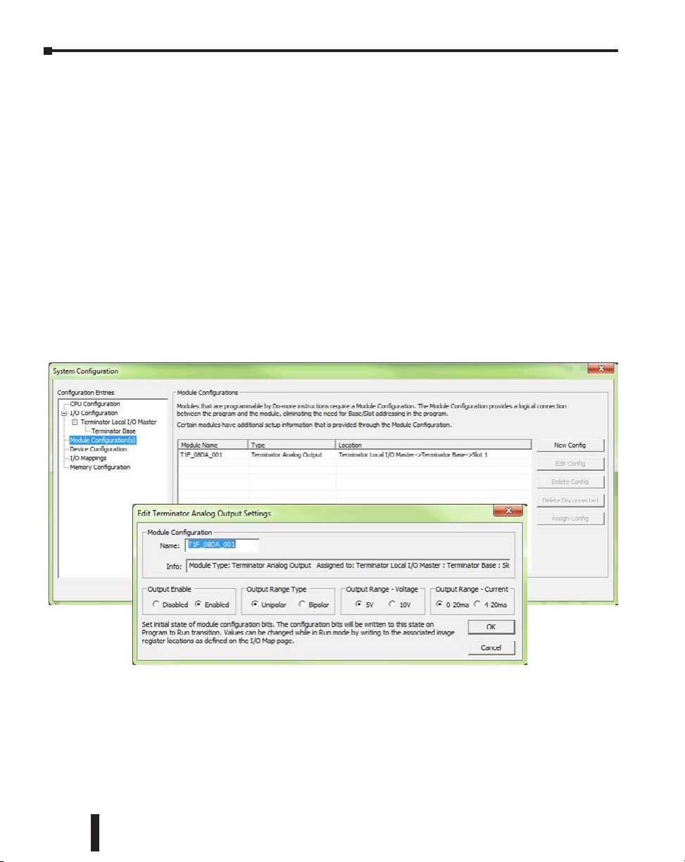
Chapter 6: Specifications - Analog I/O Modules
Analog I/O Modules Overview- continued
Module Control Byte
Analog output modules have a Module Control Byte that is used to configure some options
for the outputs. In the module addressing, this byte shows up as eight Discrete Output (Y)
Bits.
• Y0 = Outputs Enabled
• Y(0+1) = Unipolar/Bipolar
• Y(0+2) = 5V/10V Range
• Y(0+3) = 0–20mA/4–20mA
• Y((0+4) through (0+7)) = Reserved
When an analog output module is added to a Do-more project, a Module Configuration
with default Module Control Byte values is created. Its settings can be changed under
Module Configuration by double-clicking the Module Name or by selecting the New Config
or Edit Config buttons on the right hand side.
6–4
The Do-more T1H Series CPU will write the settings from the Module Configuration into
the modules before going to Run mode. The Y Bits can optionally be used to change the
Module Control Byte setting within the program.
Do-more T1H Series PLC User Manual, 1st Edition, Rev. C
Page 90

Chapter 6: Specifications - Analog I/O Modules
Analog I/O Modules Overview- continued
You can check which X, Y, WX and WY addresses are assigned to each analog I/O module in
the I/O Mapping tab of the System Configuration window, as shown below.
Select the pull-down menu PLC > System Configuration
to open the System Configuration window and click the
I/O Mapping tab.
Do-more T1H Series PLC User Manual, 1st Edition, Rev. C
6–5
Page 91

20mA
8191
Input Signal Ranges
T1F–08AD–1
1234567 0
1234567 0
48 (1.89)
) 5 1 . 3 ( 0 8
) 4 1 . 2 ( 3 . 4 5
) 1 0 . 1 ( 7 . 5 2
9.2 (0.36)
8.1 (0.32)
mm (in.)
8.1 (0.32)
Input points
Commons (not isolated)
83.3 (3.28)
2–Wire
Current
Transmitter
Fuse
Fuse
4–Wire
Current
Transmitter
Note : V1 internally
connected to Commons
1. Shields should be grounded at the signal source.
Module Supply
24 VDC
0 1 2 3 4 5 6 7
COM 0 COM 1
V 0 V 1
Equivalent Input Circuit
Chapter 6: Specifications - Analog I/O Modules
T1F-08AD-1 - 8 Channel Analog Current Input
Specifications
Number of Channels
Input Ranges
Resolution
Module Addressing
Frequency Response
Input Resistance
Absolute Maximum Ratings
Conversion Time
(Default: Normal Mode)
Linearity Error
Input Stability
Full Scale Error
(Offset Error not included)
Offset Error
Max. Full Scale Inaccuracy
(% of full scale);
all errors included
CPU Update Rate
Base Power Required
External Module Power
Supply Req.
Recommended Fuse
Operating Temperature
Storage Temperature
Accuracy vs. Temperature
Relative Humidity
Environmental Air
Vibration
Shock
Noise Immunity
Weight
8, single ended (1 common)
0–20mA, 4–20mA, -20 to 20mA
14 bit (13 bit plus sign bit)
8 input bits (X-not used); 8 input words (WX)
-3db @ 500Hz, -20db / decade
250q
8V max. Input
Normal Mode: 5ms per channel
Fast Mode: 0.5 ms per channel
(Fast Mode supported in module hardware
version B or later, and only when using this
analog module with the T1H-EBC(100) or
T1H-PBC control module)*
±2 count max.
±1 count
16 counts max.
2 counts max.
0.18% @ 25!C
0.36% @ 60!C
1 channel per scan
75mA @ 5VDC
18–30 VDC, 50mA, class 2
0.032 A @ 5VDC, Series 217 Fast Acting
0 to 60!C (32 to 140!F)
-20 to 70!C (-4 to 158!F)
±50ppm / !C max. full scale
5 to 95% (non-condensing)
No corrosive gases permitted
MIL STD 810C 514.2
MIL STD 810C 516.2
NEMA ICS3-304
136g
Equivalent Input Circuit
Input Range/Resolution
0 – 20mA
0mA
T1F-08AD-1
0 1 2 3 4 5 6 7
20mA
4mA
81910
–20 to 20mA
20mA
0mA
–20mA
* Note: T1H-PBC was
discontinued 8/2020; no
1638
8191–8191
0
replacement available
4 – 20mA
NOTES:
6–6
Do-more T1H Series PLC User Manual, 1st Edition, Rev. C
Page 92
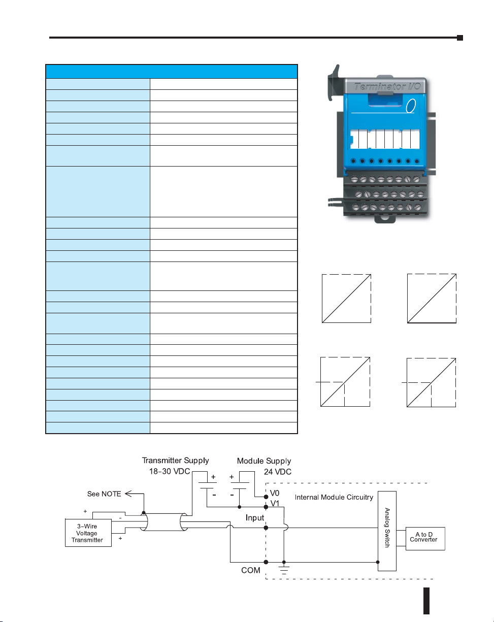
Chapter 6: Specifications - Analog I/O Modules
Equivalent Input Circuit
T1F–08AD–2
1234567 0
1234567 0
48 (1.89)
) 5 1 . 3 ( 0 8
) 4 1 . 2 ( 3 . 4 5
) 1 0 . 1 ( 7 . 5 2
9.2 (0.36)
8.1 (0.32)
mm (in.)
8.1 (0.32)
Input points
Commons (not isolated)
1. Shields should be grounded at the signal source.
4–Wire
Voltage
Transmitter
Note : V1 internally connected
to Commons
0 1 2 3 4 5 6 7
COM 0 COM 1
V 0 V 1
Module Supply
24 VDC
–819208191
–409504095
Input Signal Ranges
T1F-08AD-2 - 8 Channel Analog Voltage Input
Specifications
Number of Channels
Input Ranges
Resolution
Module Addressing
Frequency Response
Input Resistance
Absolute Maximum Ratings
Conversion Time
(Default: Normal Mode)
Linearity Error
Input Stability
Calibration Full Scale Error
Calibration Offset Error
Max. Full Scale Inaccuracy
(% of full scale);
all errors included
CPU Update Rate
Base Power Required
External Module Power
Supply Req.
Operating Temperature
Storage Temperature
Accuracy vs. Temperature
Relative Humidity
Environmental Air
Vibration
Shock
Noise Immunity
Weight
8, single ended (1 common)
0–5 V, 0–10 V, ±5V, ±10V
14 bit (13 bit plus sign bit)
8 input bits (X-not used); 8 input words (WX)
-3db @ 500Hz, -20db / decade
200kq min.
Fault Protected Input, 130V (rms)/ 100VDC
Normal Mode: 5ms per channel
Fast Mode: 0.5 ms per channel
(Fast Mode supported in
module hardware version B or later, and only
when using this analog module with the T1HEBC(100) or T1H-PBC control module)
±2 count max.
±1 count
8 counts max.
2 counts max.
0.08% @ 25!C
0.26% @ 60!C
1 channel per scan
75mA @ 5VDC
18–30 VDC, 50mA, class 2
0 to 60!C (32 to 140!F)
-20 to 70!C (-4 to 158!F)
±50ppm / !C max. full scale
5 to 95% (non-condensing)
No corrosive gases permitted
MIL STD 810C 514.2
MIL STD 810C 516.2
NEMA ICS3-304
136g
Equivalent Input Circuit
5V
0V
5V
0V
–5V
T1F-08AD-2
0 1 2 3 4 5 6 7
Input Range/Resolution
0 – 5V
10V
0V
0 4095
–5 to 5V
0 8191
–10 to 10V
10V
0V
–10V
0 – 10V
NOTES:
Do-more T1H Series PLC User Manual, 1st Edition, Rev. C
6–7
Page 93

mm (in.)
Input points
Commons (not isolated)
8910 11 12 13 1415 01 234567
) 5 1 . 3 ( 0 8
) 4 1 . 2 ( 3 . 4 5
) 1 0 . 1 ( 7 . 5 2
9.2 (0.36)
8.1 (0.32)
8.1 (0.32)
89 (3.5)
COM 0COM 1COM 2COM 3
V 0V 1
V 2V 3
83.3 (3.28)
Fuse
4–Wire
Current
Transmitter
Note: V 0 and
V 1 internally
connected
Note: V 2 and V 3 internally
connected to Commons
Fuse
2–Wire
Current
Transmitter
1. Shields should be grounded at the signal source.
Transmitter Supply
18-30 VDC
20mA
8191
Input Signal Ranges
Equivalent Input Circuit
Chapter 6: Specifications - Analog I/O Modules
T1F-16AD-1 - 16 Channel Analog Current Input
Specifications
Number of Channels
Input Ranges
Resolution
Module Addressing
Frequency Response
Input Resistance
Absolute Maximum Ratings
Conversion Time
Linearity Error
Input Stability
Full Scale Error
(Offset Error not included)
Offset Error
Max. Full Scale Inaccuracy
(% of full scale);
all errors included
CPU Update Rate
Base Power Required
External Module Power
Supply Req.
Recommended Fuse
Operating Temperature
Storage Temperature
Accuracy vs. Temperature
Relative Humidity
Environmental Air
Vibration
Shock
Noise Immunity
Weight
16, single ended (1 common)
0–20mA, 4–0mA, -20 to 20mA
14 bit (13 bit plus sign bit)
16 input bits (X-not used);
16 input words (WX)
-3db @ 500Hz, -20db / decade
250q
8V max. Input
5ms per channel
±2 count max.
±1 count
16 counts max.
2 counts max.
0.18% @ 25!C
0.36% @ 60!C
1 channel per scan
75mA @ 5VDC
18–30 VDC, 50mA, class 2
0.032 A @ 5VDC
0 to 60!C (32 to 140!F)
-20 to 70!C (-4 to 158!F)
±50ppm / !C max. full scale
5 to 95% (non-condensing)
No corrosive gases permitted
MIL STD 810C 514.2
MIL STD 810C 516.2
NEMA ICS3-304
168g
0mA
Equivalent Input Circuit
T1F-16AD-1
0 1 2 3 4 5 6 7 8 9 10 11 12 13 14 15
Input Range/Resolution
0 – 20mA
20mA
0mA
–20mA
81910
–20 to 20mA
20mA
4mA
0
4 – 20mA
1638
8191–8191
NOTES :
6–8
Do-more T1H Series PLC User Manual, 1st Edition, Rev. C
Page 94

Chapter 6: Specifications - Analog I/O Modules
mm (in.)
Input points
Commons (not isolated)
8910 11 12 13 1415 01 234567
) 5 1 . 3 ( 0 8
) 4 1 . 2 ( 3 . 4 5
) 1 0 . 1 ( 7 . 5 2
9.2 (0.36)
8.1 (0.32)
8.1 (0.32)
89 (3.5)
COM 0COM 1COM 2COM 3
V 0V 1
V 2
83.3 (3.28)
4–Wire
Voltage
Note: V 0 and
V 1 Internally
connected
Note: V 2 and V 3 internally
connected to Commons
1. Shields should be grounded at the signal source.
Transmitter Supply
18-30 VDC
V 3
Equivalent Input Circuit
–
Input Signal Ranges
T1F-16AD-2 - 16 Channel Analog Voltage Input
Specifications
Number of Channels
Input Ranges
Resolution
Module Addressing
Frequency Response
Input Resistance
Absolute Maximum Ratings
Conversion Time
Linearity Error
Input Stability
Calibration Full Scale Error
Calibration Offset Error
Max. Full Scale Inaccuracy
(% of full scale);
all errors included
CPU Update Rate
Base Power Required
External Module Power
Supply Req.
Operating Temperature
Storage Temperature
Accuracy vs. Temperature
Relative Humidity
Environmental Air
Vibration
Shock
Noise Immunity
Weight
16, single ended (1 common)
0–5 V, 0–10 V, ±5V, ±10V
14 bit (13 bit plus sign bit)
16 input bits (X-not used);
16 input words (WX)
-3db @ 500Hz, -20db / decade
200kq min.
Fault Protected Input, 130V (rms)/
100VDC
5ms per channel
±2 count max.
±1 count
8 counts max.
2 counts max.
0.08% @ 25!C
0.26% @ 60!C
1 channel per scan
75mA @ 5VDC
21.6–26.4 VDC, 50mA, class 2
0 to 60!C (32 to 140!F)
-20 to 70!C (-4 to 158!F)
±50ppm / !C max. full scale
5 to 95% (non-condensing)
No corrosive gases permitted
MIL STD 810C 514.2
MIL STD 810C 516.2
NEMA ICS3-304
160g
T1F-16AD-2
0 1 2 3 4 5 6 7 8 9 10 11 12 13 14 15
Input Range/Resolution
0 – 5V
5V
0V
0 4095
–5 to 5V
5V
0V
–5V
409504095
0 – 10V
10V
0V
0 8191
–10 to 10V
10V
0V
–10V
–819208191
NOTES:
Equivalent Input Circuit
Do-more T1H Series PLC User Manual, 1st Edition, Rev. C
6–9
Page 95

Chapter 6: Specifications - Analog I/O Modules
Equivalent Input Circuit
Equivalent Input Circuit
NOTES:
e
200 uA
Current
Source
Internal Module Circuitry
A to D
Converter
h c t i w S g o l a n A
Equivalent Input Circuit
x
See Note
Ref. Adj.
200 uA
Current
Source
200 uA
Current
Internal Module Circuitry
V 0-V 3 (RTD Returns)
CH-
CH+
T1F-16RTD - 16 Channel RTD Input
Specifications
Number of Channels
Resolution
Module Addressing
Common Mode Range
Notch Filter
Absolute Max. Ratings
Converter Type
Sampling Rate
CPU Update Rate
Base Power Required
Operating Temperature
Temperature Drift
Maximum Inaccuracy
RTD Excitation Current
Relative Humidity
Environmental Air
Vibration
Shock
Noise Immunity
Weight
16
±0.1!C or !F
16 input bits (X-broken transmitter);
16 input words (WX)
0–5 VDC
> 50db notches @ 50/60Hz; f - 3db
= 13.1 Hz
±50VDC
Charge balancing, 24-bit
140ms / channel
1 channel per scan
150mA @ 5VDC
0 to 60!C (32 to 140!F)
25ppm / !C (max.)
±1!C
200eA
5 to 95% (non-condensing)
No corrosive gases permitted
MIL STD 810C 514.2
MIL STD 810C 516.2
NEMA ICS3-304
168g
Pt100Ω -200 to 850!C (-328 to 1562!F)
Pt1000Ω -200 to 595!C (-328 to 1103!F)
jPt100Ω -38 to 450!C (-36 to 842!F)
Type CU - 10 / 25 -200 to 260! C (-328 to 500!F)
120q Nickel -80 to 260!C (-112 to 500!F)
T1F-16RTD
0 1 2 3 4 5 6 7 8 9 10 11 12 13 14 15
RTD Input Ranges
RTD Type Range
6–10
Equivalent Input Circuit
e
Red
CH-
Internal Module Circuitry
V 0-V 3 (RTD Returns)
200 uA
Current
Source
Ref. Adj.
x
CH+
See Note
Do-more T1H Series PLC User Manual, 1st Edition, Rev. C
White
1. If an RTD sensor has four wires, the plus sense wir
should be left unconnected as shown.
h c t i w S g o l a n A
200 uA
Current
Source
A to D
Converter
Page 96

Chapter 6: Specifications - Analog I/O Modules
T1F-16RTD - 16 Channel RTD Input - continued
Setting Module Jumpers
Select Number of Channels
Number of
Channels
CH+1 CH+2 CH+3 CH+4
1
2
X
3
4
X X
5
6
X X
7
8
X X X
9
10
X X
11
12
X X X
13
14
X X X
15
16
Blank Space = Jumper Removed
X X X X
X = Jumper Installed
Jumper
X
X
X X
X X
X X
X X X
°F or °C
RTD-2
RTD-1
RTD-0
X
CH+4
CH+3
CH+2
CH+1
Select Input Type
RTD Input
Pt100Ω
Pt1000Ω
jPt100Ω
Type CU-10 Ω
Type CU-25 Ω
120Ω Nickel
Blank Space = Jumper Removed
RTD-0 RTD-1 RTD-2
X X
X
X X
X = Jumper Installed
Do-more T1H Series PLC User Manual, 1st Edition, Rev. C
Jumper
X
Select Temperature Units
Temperature Unit
X
°F
°C
X = Jumper Installed
Blank Space = Jumper Removed
Jumper
°F or °C
X
6–11
Page 97

Chapter 6: Specifications - Analog I/O Modules
Equivalent Input Circuit
T1F-16TMST - 16 Channel Thermistor Input
Specifications
Number of Channels
Resolution
Input Impedence
Common Mode Range
Absolute Max. Ratings
Converter Type
Sampling Rate
Master Update Rate
Input Points Required
Base Power Required
Operating Temperature
Storage Temperature
Temperature Drift
Maximum Inaccuracy 1
Excitation Current
Electrical Isolation
Relative Humidity
Environmental Air
Vibration
Shock
Noise Immunity
Recommended Cable
Weight
1
“ Accuracy” pertains to module only and does not include tolerances
of thermistor element, wiring resistance, etc. For example, 22 gauge
wire is 0.016
2
Meets EMC & Safety Requirements
q per foot, so 200 feet of wire adds 3.2q.
Thermistor Input Ranges
Input Ranges Range
10K-AN (Type 3)
10K-CP (Type 2)
5K
3K
2252
1.8K
16
+ / - 0.1º C or ºF
> 1Mq
0 - 5 VDC
+ / - 50 VDC
Charge balancing, 24 - bit
140 ms / channel
16 channels per scan max.
512 discrete pts. or 16 dwords
(d (double) word = 32 bit word)
Network Interface dependent
150 mA @ 5 VDC
0º to 60º C (32º to 140º F)
-20º to 70º C (-4º to 158º F)
25 ppm / ºC (max.)
+ / - 1ºC
10 µA
1500VDC field wire to backplane
5 to 95% (non-condensing)
No corrosive gases permitted
IEC 60068-2-6 (Test FC)
IEC 60068-2-27 (Test Ea)
EN61131-2:2007
2
AutomationDirect P/N:
PLTC3-18-1S-XXX
Belden 8761 or equivalent
168 g
-40º to 150º C (-40º to 300º F)
-40º to 150º C (-40º to 300º F)
-40º to 150º C (-40º to 300º F)
-40º to 150º C (-40º to 300º F)
-40º to 150º C (-40º to 300º F)
-40º to 150º C (-40º to 300º F)
T1F-16TMST
0 1 2 3 4 5 6 7 8 9 10 11 12 13 14 15
CHxA
CHxB
Field side ground
CH1ACH2ACH3ACH4ACH5ACH6ACH7ACH8ACH9ACH10ACH11ACH12ACH13ACH14ACH15
CH1BCH2BCH3BCH4BCH5BCH6BCH7BCH8BCH9BCH10BCH11BCH12BCH13BCH14BCH15
If inputs are not used, tie CHxA and CHxB
together to COMMON terminal block.
Tie COMMONS to field side ground.
Internal Module Circuitry
COMMON (V0 - V3)
Channel Inputs (+)
Channel Inputs (–)
Commons
Analog Switch
Ref. Adj.
10 uA
Current
Source
A to D
Converter
A
B
CH16
A
CH16
B
6–12
Do-more T1H Series PLC User Manual, 1st Edition, Rev. C
Page 98

Chapter 6: Specifications - Analog I/O Modules
T1F-16TMST - 16 Channel Thermistor Input - continued
Setting Module Jumpers
Select Number of Channels
Number of
Channels
1
2 X
3 X
4 X X
5 X
6 X X
7 X X
8 X X X
9 X
10 X X
11 X X
12 X X X
13 X X
14 X X X
15 X X X
16 X X X X
CH+1 CH+2 CH+3 CH+4
X = Jumper Installed
Blank Space = Jumper Removed
Jumper
Select Input Type
Jumper
Thermistor Input
10K-AN (Type 3)
10K-CP (Type 2) X
5K X
3K X X
2252 X
1.8K X X
Future use X X
Future use X X X
TMST-0 TMST-1 TMST-2
°F or °C
TMST-2
TMST-1
TMST-0
CH+4
CH+3
CH+2
CH+1
Select Temperature Units
Temperature Unit
°F
°C
X = Jumper Installed
Blank Space = Jumper Removed
Jumper
°F or °C
X
X = Jumper Installed
Blank Space = Jumper Removed
Do-more T1H Series PLC User Manual, 1st Edition, Rev. C
6–13
Page 99

Chapter 6: Specifications - Analog I/O Modules
–3276
Voltage Input Signal Ranges
Equivalent Input Circuit
T1F-14THM - 14 Channel Thermocouple Input
Specifications
Use with I/O Module Base
Number of Channels
Common Mode Range
Module Addressing
Common Mode Rejection
Input Impedance
Absolute Max. Ratings
CPU Update Rate
Base Power Required
External Power Required
Operating Temperature
Storage Temperature
Accuracy vs. Temperature
Relative Humidity
Environmental Air
Vibration
Shock
Noise Immunity
Weight
Thermocouple Specifications
Input Ranges
Display Resolution
Cold Junction Compensation
Conversion Time
Warm Up Time
Linearity Error
Maximum Inaccuracy
Equivalent Input Circuit
T1K-16B screw type terminal base only
14, differential
±5VDC
16 input bits (X-broken transmitter);
16 input words (WX)
90db min. @ DC, 150db min . @ 50/60Hz
1Mq
Fault Protected Input ±50VDC
1 channel per scan
60mA @ 5VDC
24VDC ±5%, 70mA, class 2
0 to 60!C (-4 to 158!F)
-20 to 70!C (32 to 140!F)
±5ppm/ !C max. full scale
5 to 95% (non-condensing)
No corrosive gases permitted
MIL STD 810C 514.2
MIL STD 810C 516.2
NEMA ICS3-304
168g
Type J -190 to 760!C (-310 to 1400!F)
Type E -210 to 1000!C (-346 to 1832!F)
Type K -150 to 1372!C (-238 to 2502!F)
Type R 65 to 1768!C (149 to 3214!F)
Type S 65 to 1768!C (149 to 3214!F)
Type T -230 to 400!C (-382 to 752!F)
Type B 529 to 1820!C (984 to 3308!F)
Type N -70 to 1300!C (-94 to 2372!F)
Type C 65 to 2320!C (149 to 4208!F)
±0.1!C or ±0.1!F
Automatic (CJC Part #: T1F-CJC)
100ms per channel
30 minutes typical, ±1!C repeatability
±0.05!C maximum, ±0.01!C typical
±3!C
T1F-14THM
0 1 2 3 4 5 6 7 8 9 10 11 12 13 14 15
Voltage Specifications
Input Voltage
Ranges
Resolution
Full Scale
Calibration
Error (Offset
Error Included)
Offset
Calibration
Error
Linearity Error
(End to End)
Maximum
Inaccuracy
Input Range/Resolution
0 – 5V
5V
0V
0 65535
–5 to 5V
5V
0–5 V, 0–156.25 mV
±5V, ±156.25 mV
16 bit (1 in 65535)
±13 counts typical
±33 counts maximum
±1 count max. @ 0V input
±1 count maximum
± 0.02% @ 25! C (77!F)
0 – 156.25mV
156.25mV
0V
0 65535
+ / – 156.25 mV
156.25mV
6–14
0V
7032767
Do-more T1H Series PLC User Manual, 1st Edition, Rev. C
0V
–156.25mV
–32767032767
Page 100
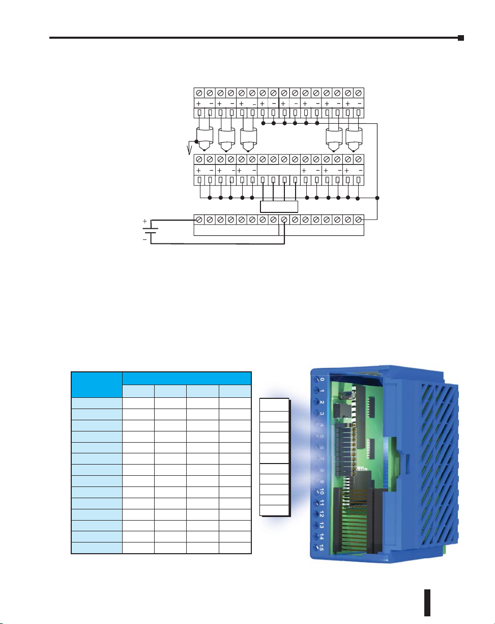
Chapter 6: Specifications - Analog I/O Modules
9.2 (0.36)
8.1 (0.32)
8.1 (0.32)
89 (3.5)
83.3 (3.28)
T1F–14THM
T1F-14THM - 14 Channel Thermocouple Input - continued
Input points
Top
Row
8 7 6 5 4 3 2 1
Differential
thermocouple
wiring
Grounded
thermocouple
wiring
See Notes 1 and 2
Module Supply
24 VDC
910111213 14
CJC
CJC
24 V
NOTES:
1. Shields should be grounded at the signal source.
2. Unused inputs should be connected to Common (0 VDC).
3. The Cold Junction Compensation (part #: T1F–CJC)
temperature sense unit that comes with the module
must be installed into the I/O base terminals to perform
CJC of the thermocouple inputs.
Setting Module Jumpers (See Notes 1 and 2)
Select Number of Channels
Number of
Channels
CH+1 CH+2 CH+4 CH+8
1
2
X
3
4
X X
5
6
X X
7
8
X X X
9
10
X X
11
12
X X X
13
14
X X X X
X = Jumper Installed
Blank Space = Jumper Removed
Jumper
X
X
X X
X X
X X
Calibrate
Enable
Units-1
Units-0
T/C Type 3
T/C Type 2
T/C Type 1
T/C Type 0
CH+8
CH+4
X
CH+2
CH+1
See Note 3
0 V
Bottom
Row
Do-more T1H Series PLC User Manual, 1st Edition, Rev. C
6–15
 Loading...