

Page 1

SGW Series
Modbus Gateway
USER MANUAL
Manual Number: SGW-USER-M
Page 2

Page 3

~ WARNING ~
Thank you for purchasing automation equipment from Automationdirect.com®, doing business as
AutomationDirect. We want your new automation equipment to operate safely. Anyone who installs
or uses this equipment should read this publication (and any other relevant publications) before
installing or operating the equipment.
To minimize the risk of potential safety problems, you should follow all applicable local and national
codes that regulate the installation and operation of your equipment. These codes vary from area
to area and usually change with time. It is your responsibility to determine which codes should be
followed, and to verify that the equipment, installation, and operation is in compliance with the latest
revision of these codes.
At a minimum, you should follow all applicable sections of the National Fire Code, National Electrical
Code, and the codes of the National Electrical Manufacturer’s Association (NEMA). There may be
local regulatory or government offices that can also help determine which codes and standards are
necessary for safe installation and operation.
Equipment damage or serious injury to personnel can result from the failure to follow all applicable
codes and standards. We do not guarantee the products described in this publication are suitable for
your particular application, nor do we assume any responsibility for your product design, installation,
or operation.
Our products are not fault-tolerant and are not designed, manufactured or intended for use or resale
as on-line control equipment in hazardous environments requiring fail-safe performance, such as in
the operation of nuclear facilities, aircraft navigation or communication systems, air traffic control,
direct life support machines, or weapons systems, in which the failure of the product could lead
directly to death, personal injury, or severe physical or environmental damage (“High Risk Activities”).
AutomationDirect specifically disclaims any expressed or implied warranty of fitness for High Risk
Activities.
For additional warranty and safety information, see the Terms and Conditions on our website. If
you have any questions concerning the installation or operation of this equipment, or if you need
additional information, please call us at 770-844-4200.
This publication is based on information that was available at the time it was published. At
AutomationDirect we constantly strive to improve our products and services, so we reserve the right
to make changes to the products and/or publications at any time without notice and without any
obligation. This publication may also discuss features that may not be available in certain revisions of
the product.
Trademarks
This publication may contain references to products produced and/or offered by other companies.
The product and company names may be trademarked and are the sole property of their respective
owners. AutomationDirect disclaims any proprietary interest in the marks and names of others.
Copyright 2018–2021 Automationdirect.com® Incorporated
All Rights Reserved
No part of this manual shall be copied, reproduced, or transmitted in any way without the prior,
written consent of Automationdirect.com® Incorporated. AutomationDirect retains the exclusive
rights to all information included in this document.
Page W–1Stride® MB Gateway User Manual – 1st Edition Rev. F – April 2021
Page 4

~ ADVERTENCIA ~
Gracias por comprar equipo de automatización de Automationdirect.com®. Deseamos que su nuevo
equipo de automatización opere de manera segura. Cualquier persona que instale o use este equipo debe
leer esta publicación (y cualquier otra publicación pertinente) antes de instalar u operar el equipo.
Para reducir al mínimo el riesgo debido a problemas de seguridad, debe seguir todos los códigos
de seguridad locales o nacionales aplicables que regulan la instalación y operación de su equipo.
Estos códigos varian de área en área y usualmente cambian con el tiempo. Es su responsabilidad
determinar cuales códigos deben ser seguidos y verificar que el equipo, instalación y operación estén en
cumplimiento con la revisión mas reciente de estos códigos.
Como mínimo, debe seguir las secciones aplicables del Código Nacional de Incendio, Código Nacional
Eléctrico, y los códigos de (NEMA) la Asociación Nacional de Fabricantes Eléctricos de USA. Puede haber
oficinas de normas locales o del gobierno que pueden ayudar a determinar cuales códigos y normas son
necesarios para una instalación y operación segura.
Si no se siguen todos los códigos y normas aplicables, puede resultar en daños al equipo o lesiones serias
a personas. No garantizamos los productos descritos en esta publicación para ser adecuados para su
aplicación en particular, ni asumimos ninguna responsabilidad por el diseño de su producto, la instalación
u operación.
Nuestros productos no son tolerantes a fallas y no han sido diseñados, fabricados o intencionados para
uso o reventa como equipo de control en línea en ambientes peligrosos que requieren una ejecución sin
fallas, tales como operación en instalaciones nucleares, sistemas de navegación aérea, o de comunicación,
control de tráfico aéreo, máquinas de soporte de vida o sistemas de armamentos en las cuales la falla
del producto puede resultar directamente en muerte, heridas personales, o daños físicos o ambientales
severos (“Actividades de Alto Riesgo”). Automationdirect.com específicamente rechaza cualquier garantía
ya sea expresada o implicada para actividades de alto riesgo.
Para información adicional acerca de garantía e información de seguridad, vea la sección de Términos
y Condiciones. Si tiene alguna pregunta sobre instalación u operación de este equipo, o si necesita
información adicional, por favor llámenos al número 770-844-4200 en Estados Unidos.
Esta publicación está basada en la información disponible al momento de la publicación. En
Automationdirect.com nos esforzamos constantemente para mejorar nuestros productos y servicios,
así que nos reservamos el derecho de hacer cambios al producto y/o a las publicaciones en cualquier
momento sin notificación y sin ninguna obligación. Esta publicación también puede discutir
características que no estén disponibles en ciertas revisiones del producto.
Marcas Registradas
Esta publicación puede contener referencias a productos producidos y/u ofrecidos por otras compañías.
Los nombres de las compañías y productos pueden tener marcas registradas y son propiedad única de
sus respectivos dueños. Automationdirect.com, renuncia cualquier interés propietario en las marcas y
nombres de otros.
Propiedad Literaria 2018–2021, Automationdirect.com® Incorporated
Todos los derechos reservados
No se permite copiar, reproducir, o transmitir de ninguna forma ninguna parte de este manual sin previo
consentimiento por escrito de Automationdirect.com® Incorporated. Automationdirect.com retiene
los derechos exclusivos a toda la información incluida en este documento. Los usuarios de este equipo
pueden copiar este documento solamente para instalar, configurar y mantener el equipo correspondiente.
También las instituciones de enseñanza pueden usar este manual para propósitos educativos.
Page W–2 Stride® MB Gateway User Manual – 1st Edition Rev. F – April 2021
Page 5

~ AVERTISSEMENT ~
Nous vous remercions d’avoir acheté l’équipement d’automatisation de Automationdirect.com®, en faisant
des affaires comme AutomationDirect. Nous tenons à ce que votre nouvel équipement d’automatisation
fonctionne en toute sécurité. Toute personne qui installe ou utilise cet équipement doit lire la présente
publication (et toutes les autres publications pertinentes) avant de l’installer ou de l’utiliser.
Afin de réduire au minimum le risque d’éventuels problèmes de sécurité, vous devez respecter tous les
codes locaux et nationaux applicables régissant l’installation et le fonctionnement de votre équipement.
Ces codes diffèrent d’une région à l’autre et, habituellement, évoluent au fil du temps. Il vous incombe de
déterminer les codes à respecter et de vous assurer que l’équipement, l’installation et le fonctionnement
sont conformes aux exigences de la version la plus récente de ces codes.
Vous devez, à tout le moins, respecter toutes les sections applicables du Code national de prévention
des incendies, du Code national de l’électricité et des codes de la National Electrical Manufacturer’s
Association (NEMA). Des organismes de réglementation ou des services gouvernementaux locaux peuvent
également vous aider à déterminer les codes ainsi que les normes à respecter pour assurer une installation
et un fonctionnement sûrs.
L’omission de respecter la totalité des codes et des normes applicables peut entraîner des dommages
à l’équipement ou causer de graves blessures au personnel. Nous ne garantissons pas que les produits
décrits dans cette publication conviennent à votre application particulière et nous n’assumons aucune
responsabilité à l’égard de la conception, de l’installation ou du fonctionnement de votre produit.
Nos produits ne sont pas insensibles aux défaillances et ne sont ni conçus ni fabriqués pour l’utilisation ou
la revente en tant qu’équipement de commande en ligne dans des environnements dangereux nécessitant
une sécurité absolue, par exemple, l’exploitation d’installations nucléaires, les systèmes de navigation
aérienne ou de communication, le contrôle de la circulation aérienne, les équipements de survie ou
les systèmes d’armes, pour lesquels la défaillance du produit peut provoquer la mort, des blessures
corporelles ou de graves dommages matériels ou environnementaux («activités à risque élevé»). La
société AutomationDirect nie toute garantie expresse ou implicite d’aptitude à l’emploi en ce qui a trait aux
activités à risque élevé.
Pour des renseignements additionnels touchant la garantie et la sécurité, veuillez consulter la section
Modalités et conditions de notre documentation. Si vous avez des questions au sujet de l’installation
ou du fonctionnement de cet équipement, ou encore si vous avez besoin de renseignements
supplémentaires, n’hésitez pas à nous téléphoner au 770-844-4200.
Cette publication s’appuie sur l’information qui était disponible au moment de la publication. À la société
AutomationDirect, nous nous efforçons constamment d’améliorer nos produits et services. C’est pourquoi
nous nous réservons le droit d’apporter des modifications aux produits ou aux publications en tout
temps, sans préavis ni quelque obligation que ce soit. La présente publication peut aussi porter sur des
caractéristiques susceptibles de ne pas être offertes dans certaines versions révisées du produit.
Marques de commerce
La présente publication peut contenir des références à des produits fabriqués ou offerts par d’autres
entreprises. Les désignations des produits et des entreprises peuvent être des marques de commerce et
appartiennent exclusivement à leurs propriétaires respectifs. AutomationDirect nie tout intérêt dans les
autres marques et désignations.
Copyright 2018–2021 Automationdirect.com® Incorporated
Tous droits réservés
Nulle partie de ce manuel ne doit être copiée, reproduite ou transmise de quelque façon que ce soit sans
le consentement préalable écrit de la société Automationdirect.com® Incorporated. AutomationDirect
conserve les droits exclusifs à l’égard de tous les renseignements contenus dans le présent document.
Page W–3Stride® MB Gateway User Manual – 1st Edition Rev. F – April 2021
Page 6

Warnings
WARNING:
SuItAble foR uSe IN ClASS I, DIvISIoN 2, GRoupS A, b, C AND D HAzARDouS loCAtIoNS, oR
NoNHAzARDouS loCAtIoNS oNly.
Cet AppAReIllAGe eSt utIlISAble DANS leS emplACemeNtS De ClASSe I, DIvISIoN 2, GRoupeS A, b, C
et D, ou DANS leS emplACemeNtS NoN DANGeReux SeulemeNt.
WARNING: exploSIoN HAzARD
• Do Not DISCoNNeCt equIpmeNt WHIle tHe CIRCuIt IS lIve oR uNleSS tHe AReA IS kNoWN
• SubStItutIoN of ANy CompoNeNt mAy ImpAIR SuItAbIlIty foR ClASS I, DIvISIoN 2.
AveRtISSemeNt: RISque D’exploSIoN
• AvANt De DeCoNNeCteR l’equIpemeNt, CoupeR le CouRANt ou S’ASSuReR que
• lA SubStItutIoN De CompoSANtS peut ReNDRe Ce mAteRIel INACCeptAble pouR leS
to be fRee of IGNItAble CoNCeNtRAtIoNS.
l’emplACemeNt eSt DeSIGNe NoN DANGeReux.
emplACemeNtS De ClASSe I, DIvISIoN 2.
Page W–4 Stride® MB Gateway User Manual – 1st Edition Rev. F – April 2021
Page 7

Stride® MB Gateway
User ManUal revision History
Please include this Manual Number and the Manual Issue, both shown below, when communicating with
AutomationDirect Technical Support regarding this publication.
Manual Number: SGW-USER-M
Manual Issue: 1st Edition, Revision F
Issue Date: April 1, 2021
Publication History
Issue Date Description of Changes
First Edition 03/28/2018 Initial Release
1st Edition, Revision A 06/29/2018 Clarified input voltage range, clarified supported web browsers.
1st Edition, Revision B 10/26/2018 Updated IP addresses in Application Examples.
1st Edition, Revision C 09/09/2019 Updated screenshots, minor clarifications.
1st Edition, Revision D 02/12/2020 Added Appendix D: Security Considerations for Control Systems Networks.
1st Edition, Revision E 08/17/2020 Clarified imported configuration filenames.
1st Edition, Revision F 04/01/2021 Corrected terminating resistor on RS-485 wiring diagrams.
Page H–iStride® MB Gateway User Manual – 1st Edition Rev. F – April 2021
Page 8

User Manual Revision History
BLANK
PAG E
Page H–ii Stride® MB Gateway User Manual – 1st Edition Rev. F – April 2021
Page 9

Stride® ModbuS Gateway
User ManUal Table of ConTenTs
ConTenTs
ConTenTs
ConTenTs
C
hapter
User Manual Overview � � � � � � � � � � � � � � � � � � � � � � � � � � � � � � � � � � � � � � 1–2
Introduction � � � � � � � � � � � � � � � � � � � � � � � � � � � � � � � � � � � � � � � � � � � � 1–3
Product Overview � � � � � � � � � � � � � � � � � � � � � � � � � � � � � � � � � � � � � � � � � 1–3
Hardware � � � � � � � � � � � � � � � � � � � � � � � � � � � � � � � � � � � � � � � � � � � � � � 1–3
Installation, DIN Rail Mounting� � � � � � � � � � � � � � � � � � � � � � � � � � � � � � � � � � 1–6
Dimensional Drawings � � � � � � � � � � � � � � � � � � � � � � � � � � � � � � � � � � � � � � 1–7
Wiring � � � � � � � � � � � � � � � � � � � � � � � � � � � � � � � � � � � � � � � � � � � � � � � 1–8
Operation � � � � � � � � � � � � � � � � � � � � � � � � � � � � � � � � � � � � � � � � � � � � � 1–11
1: G
ettinG StartinG
Hardware Reset Button � � � � � � � � � � � � � � � � � � � � � � � � � � � � � � � � � � � � � � � 1–5
DIP Switches � � � � � � � � � � � � � � � � � � � � � � � � � � � � � � � � � � � � � � � � � � � � � 1–5
LEDs � � � � � � � � � � � � � � � � � � � � � � � � � � � � � � � � � � � � � � � � � � � � � � � � � � 1–5
Power � � � � � � � � � � � � � � � � � � � � � � � � � � � � � � � � � � � � � � � � � � � � � � � � � 1–8
Ethernet Wiring � � � � � � � � � � � � � � � � � � � � � � � � � � � � � � � � � � � � � � � � � � � 1–9
Serial Port Wiring � � � � � � � � � � � � � � � � � � � � � � � � � � � � � � � � � � � � � � � � � 1–10
Transparent Mode � � � � � � � � � � � � � � � � � � � � � � � � � � � � � � � � � � � � � � � � � 1–11
Agent Mode � � � � � � � � � � � � � � � � � � � � � � � � � � � � � � � � � � � � � � � � � � � � 1–11
. . . . . . . . . . . . . . . . . . . . . . . . . . . . 1–1
C
hapter
Introduction � � � � � � � � � � � � � � � � � � � � � � � � � � � � � � � � � � � � � � � � � � � � 2–2
Mode 1: Transparent, RTU Master mode:
Mode 2: Agent, RTU Master mode:
Mode 3: Transparent, RTU Slave mode:
Mode 4: Agent, RTU Slave mode:
C
hapter
Initial Connection � � � � � � � � � � � � � � � � � � � � � � � � � � � � � � � � � � � � � � � � � �3-2
Device Info Page� � � � � � � � � � � � � � � � � � � � � � � � � � � � � � � � � � � � � � � � � � �3-3
Network Settings � � � � � � � � � � � � � � � � � � � � � � � � � � � � � � � � � � � � � � � � � �3-4
Operating Settings � � � � � � � � � � � � � � � � � � � � � � � � � � � � � � � � � � � � � � � � �3-5
Serial Settings � � � � � � � � � � � � � � � � � � � � � � � � � � � � � � � � � � � � � � � � � � � �3-7
2: S
ummary of modbuS modeS
Modbus TCP Client/Master Device to Gateway to Modbus RTU Slave Devices � � � � � � 2–3
Modbus TCP Client/Master Device to Gateway Memory� Gateway Talks Directly to Modbus
RTU Slave Devices � � � � � � � � � � � � � � � � � � � � � � � � � � � � � � � � � � � � � � � � 2–4
Modbus RTU Master Device to Gateway to Modbus TCP Server/Slave Devices � � � � � � 2–6
Modbus RTU Master Device to Gateway Memory� Gateway Talks Directly to Modbus TCP
Server/Slave Devices � � � � � � � � � � � � � � � � � � � � � � � � � � � � � � � � � � � � � � � 2–7
3: Web C
For Modbus RTU/ASCII Master to Modbus TCP Servers (Slaves) � � � � � � � � � � � � � � � � 3-5
For Modbus TCP Master (Client) Device to Modbus RTU/ASCII Slave Devices � � � � � � � � � 3-6
onSole ConfiGuration
. . . . . . . . . . . . . . . . . . . . . 2–1
. . . . . . . . . . . . . . . . . . . . . 3-1
TOC–1Stride® MB Gateway User Manual – 1st Edition Rev. F – April 2021
Page 10

Table of Contents
Agent Settings � � � � � � � � � � � � � � � � � � � � � � � � � � � � � � � � � � � � � � � � � � � �3-8
Gateway Settings� � � � � � � � � � � � � � � � � � � � � � � � � � � � � � � � � � � � � � � � � � � 3-8
Message List � � � � � � � � � � � � � � � � � � � � � � � � � � � � � � � � � � � � � � � � � � � � � 3-9
Data in Gateway Memory � � � � � � � � � � � � � � � � � � � � � � � � � � � � � � � � � � � � � �3-11
Import/Export � � � � � � � � � � � � � � � � � � � � � � � � � � � � � � � � � � � � � � � � � � � 3-12
Export � � � � � � � � � � � � � � � � � � � � � � � � � � � � � � � � � � � � � � � � � � � � � � � � �3-12
Import� � � � � � � � � � � � � � � � � � � � � � � � � � � � � � � � � � � � � � � � � � � � � � � � �3-12
Upgrade Firmware� � � � � � � � � � � � � � � � � � � � � � � � � � � � � � � � � � � � � � � � � 3-13
Change Password � � � � � � � � � � � � � � � � � � � � � � � � � � � � � � � � � � � � � � � � � 3-14
Load Factory Default � � � � � � � � � � � � � � � � � � � � � � � � � � � � � � � � � � � � � � � 3-15
Reboot � � � � � � � � � � � � � � � � � � � � � � � � � � � � � � � � � � � � � � � � � � � � � � � 3-16
a
ppendix
Example 1:
Using Modbus Poll to STRIDE Modbus Gateway with BRX Slave � � � � � � � � � � � � � � A–2
Example 2:
Using Modbus Poll to STRIDE MB Gateway with CLICK Slave � � � � � � � � � � � � � � � � A–9
Example 3:
Using P3000 as Master (Client) to STRIDE Modbus Gateway with CLICK Slave� � � � � � �A–17
a: a
ppliCation exampleS
. . . . . . . . . . . . . . . . . . . . . . . . . a–1
a
ppendix
b: S
tride modbuS GateWay operatinG mode exampleS
. . . . . . . . b–1
Example 1:
TRANSPARENT Mode, with Modbus TCP Master (Client) Devices to
Modbus RTU/ASCII Slave Devices� � � � � � � � � � � � � � � � � � � � � � � � � � � � � � � � B–2
Example 2:
TRANSPARENT Mode, with Modbus RTU/ASCII Master Devices to
Modbus TCP Slave (Server) Devices� � � � � � � � � � � � � � � � � � � � � � � � � � � � � � � B–6
Example 3:
AGENT Mode, with Modbus TCP Master (Client) Devices to
Modbus RTU/ASCII Slave Devices� � � � � � � � � � � � � � � � � � � � � � � � � � � � � � � � B–11
Example 4:
AGENT Mode, with Modbus RTU/ASCII Master Devices to
Modbus TCP Slave (Server) Devices� � � � � � � � � � � � � � � � � � � � � � � � � � � � � � � B–16
a
ppendix
C: m
odbuS error CodeS
. . . . . . . . . . . . . . . . . . . . . . . . . C–1
Modbus Error Codes � � � � � � � � � � � � � � � � � � � � � � � � � � � � � � � � � � � � � � � C–2
a
ppendix
d: S
eCurity ConSiderationS for Control SyStemS netWorkS
. . . . . d-1
Security Considerations for Control Systems Networks � � � � � � � � � � � � � � � � � � � � D-2
TOC–2 Stride® MB Gateway User Manual – 1st Edition Rev. F – April 2021
Page 11

Chapter
Chapter
Chapter
GettinG Started
1
1
1
in t
hiS Chapter
User Manual Overview � � � � � � � � � � � � � � � � � � � � � � � � � � � � � � � � � � � � � � � � �1–2
Introduction � � � � � � � � � � � � � � � � � � � � � � � � � � � � � � � � � � � � � � � � � � � � � � �1–3
Product Overview � � � � � � � � � � � � � � � � � � � � � � � � � � � � � � � � � � � � � � � � � � � �1–3
Hardware � � � � � � � � � � � � � � � � � � � � � � � � � � � � � � � � � � � � � � � � � � � � � � � � �1–3
Hardware Reset Button � � � � � � � � � � � � � � � � � � � � � � � � � � � � � � � � � � � � � � � � � � � � 1–5
DIP Switches � � � � � � � � � � � � � � � � � � � � � � � � � � � � � � � � � � � � � � � � � � � � � � � � � � 1–5
LEDs� � � � � � � � � � � � � � � � � � � � � � � � � � � � � � � � � � � � � � � � � � � � � � � � � � � � � � � 1–5
Installation, DIN Rail Mounting� � � � � � � � � � � � � � � � � � � � � � � � � � � � � � � � � � � � �1–6
Dimensional Drawings � � � � � � � � � � � � � � � � � � � � � � � � � � � � � � � � � � � � � � � � �1–7
Wiring � � � � � � � � � � � � � � � � � � � � � � � � � � � � � � � � � � � � � � � � � � � � � � � � � �1–8
Power � � � � � � � � � � � � � � � � � � � � � � � � � � � � � � � � � � � � � � � � � � � � � � � � � � � � � � 1–8
Ethernet Wiring � � � � � � � � � � � � � � � � � � � � � � � � � � � � � � � � � � � � � � � � � � � � � � � � 1–9
Serial Port Wiring � � � � � � � � � � � � � � � � � � � � � � � � � � � � � � � � � � � � � � � � � � � � � � � 1–10
Operation � � � � � � � � � � � � � � � � � � � � � � � � � � � � � � � � � � � � � � � � � � � � � � � 1–11
Transparent Mode � � � � � � � � � � � � � � � � � � � � � � � � � � � � � � � � � � � � � � � � � � � � � � �1–11
Agent Mode � � � � � � � � � � � � � � � � � � � � � � � � � � � � � � � � � � � � � � � � � � � � � � � � � � 1–11
...
Page 1–1Stride® MB Gateway User Manual – 1st Edition Rev. F – April 2021
Page 12

Chapter 1: Getting Started
User Manual Overview
The Purpose of this User’s Manual
Thank you for purchasing our STRIDE® Modbus Gateway. This User Manual describes the gateway
and its specifications, and guides you in the installation, configuration, and methods of operation
of the STRIDE®Modbus gateway.
Who Should Read This Manual
This manual contains important information for those who will install, maintain, and/or operate a
STRIDE® Modbus Gateway.
Technical Support
By Telephone: 770-844-4200
(Mon.–Fri., 9:00 a.m.–6:00 p.m. E.T.)
On the Web: www.automationdirect.com
Our technical support group is glad to work with you in answering your questions. If you cannot
find the solution to your particular application, or, if for any reason you need additional technical
assistance, please call technical support at 770-844-4200. We are available weekdays from 9:00
a.m. to 6:00 p.m. Eastern Time.
We also encourage you to visit our web site where you can find technical and non-technical
information about our products and our company. Visit us at www.automationdirect.com.
Special Symbols
NOTE: When you see the “notepad” icon in the left-hand margin, the paragraph to its immediate
right will be a special note.
SECURITY NOTE: When you see the “padlock” icon in the left-hand margin, the paragraph to its
immediate right will be a security-related suggestion or note.
WARNING: WheN you see the “exclAmAtIoN mARk” IcoN IN the left-hANd mARGIN, the pARAGRAph to
Its ImmedIAte RIGht WIll be A WARNING. thIs INfoRmAtIoN could pReveNt INjuRy, loss of pRopeRty, oR
eveN deAth (IN extReme cAses).
Page 1–2 Stride® MB Gateway User Manual – 1st Edition Rev. F – April 2021
Page 13
Introduction
Modbus is one of the most popular communication protocols in the automation industry because
it supports both traditional RS-232/422/485 devices and industrial Ethernet devices. Many
industrial devices, such as PLCs, HMIs, instruments and meters use Modbus as their standard
communication protocol. However, the Modbus protocols running over serial and Ethernet are so
different that a communication gateway is needed as a bridge for integrating devices from these
two networks. The STRIDE® Modbus Gateway provides that bridge between Modbus RTU (Serial)
products and Modbus TCP (Ethernet) products.
The gateway converts bidirectionally between Modbus RTU or Modbus ASCII protocols and
Modbus TCP. In addition to its compact size, the gateway features up to two 10/100 Mbps Ethernet
ports and up to four RS232/422/485 serial ports.
SECURITY NOTE: When implementing any method of remote access to your equipment, you
need to consider the security exposure in order to minimize the risks to your processes and
your equipment. Security should always be carefully evaluated for each installation. Refer to
“Appendix D: Security Considerations for Control Systems Networks” for more information.
Product Overview
Chapter 1: Getting Started
.
Key features include:
9
Industrial 1, 2, or 4 serial port, and 1 or 2 Ethernet port Modbus Gateways
(Modbus RTU/ASCII <-> ModbusTCP)
9
Automatic read function “Agent Mode”
9
Ethernet ports each support up to 16 TCP devices, client or server
9
Serial ports each support up to 128 slave devices or 1 master device
9
DIP switch selectable termination resistor for RS-485 2-wire mode
9
High Serial Isolation Voltage (2kV)
9
UL61010 with Class 1 Division 2 hazardous location rating
9
Metal housing with wide temperature rating (−40 to +75°C)
Hardware
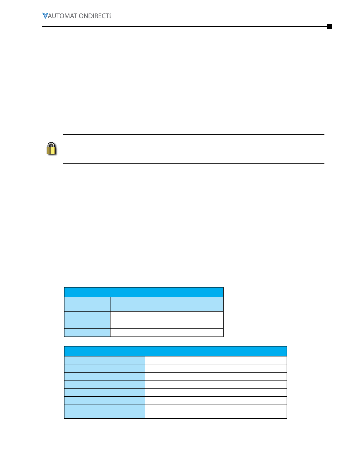
Part Number
SGW-MB1511-T
SGW-MB1512-T
SGW-MB1524-T
Port
Speed
Protection
Protocol Supported
Modbus TCP devices supported
Cable Type
Default IP address
STRIDE Modbus Gateway Models
Ethernet Ports
RJ45, 10/100Mbps
1 1
1 2
2 4
Serial Ports
D-sub 9 pin
Ethernet Interface
Built-in 1�5 kV magnetic isolation
Modbus TCP/IP client and server
16 simultaneous Modbus TCP connections per Ethernet port
Autodetects Ethernet cable types (MDI/MDIX)
192�168�1�249 (Ethernet Port 2, SGW-MB1524-T)
Shielded RJ45
10/100 Mbps
192�168�0�249
Page 1–3Stride® MB Gateway User Manual – 1st Edition Rev. F – April 2021
Page 14

Chapter 1: Getting Started
Port
Interface mode
Supported Baud Rates
Parity
Data Bits
Stop Bits
Flow control
Termination
ESD Protection
Isolation Protection
Serial Interface
D-sub 9-pin male port
RS-232, RS-485 and RS-422, software selectable
300, 600, 1200, 4800, 9600, 14�4k, 19�2k,
38�4k, 57�6k, 115.2k, 230�4k, 460�8k
Odd, Even or None
7 or 8 bits
1 or 2
RTS/CTS, XON/XOFF or None
DIP switch to enable/disable 120Ω matching resistor
for RS-485 2-wire
15kV for all signals
2kV
Serial Devices Supported
Protocols Supported
Note: Default values are shown in bold text.
Power Details
SGW-MB1511-T 1�8 W
Power Consumption
SGW-MB1512-T 1�8 W
SGW-MB1524-T 3�2 W
Power Input
Input Voltage
Max. Input Voltage Range
Appliance Class
Reverse Power Protection
Overload Protection
Environmental
Operating Temperature Range
Storage Temperature Range
Humidity
Maximum Altitude
Environmental Air
Protection level
Agency Approvals
EMI
EMS
Mechanical Standards
For use in Pollution Degree 2 Environment
UL61010-1, UL61010-2-201, Class I Div 2 12�12�01-
2015; CSA C22�2 No� 213-16; CAN/CSA No� 61010-1-12;
CAN/CSAC22�2 No� 61010-2-201:14, CE, FCC
IEC 61000-4-2 (ESD): ±6kV (contact), ±8kV (air)
IEC 61000-4-3 (RS): 10V/m (80MHz–2GHz)
IEC 61000-4-4 (EFT): Power Port: ±2kV; Data Port: ±1kV
IEC 61000-4-5 (Surge): PowerPort: ±1kV/DM, ±2kV/CM;
IEC 61000-4-6 (CS): 10V (150KHz–80MHz)
128 slaves or 1 master per port
Modbus RTU, Modbus ASCII
Redundant input terminals
12 / 24 / 48 VDC
9�6 – 60 VDC
Class III, SELV power source
Yes
Yes
-40 to +75 °C [-40 to +167 °F]
-40 to +85 °C [-40 to +185 °F]
5 to 95% RH (non-condensing)
2000m
Metal case, IP40
EN 55032 Class A
FCC Part 15 Subpart B Class A
Data Port: ±1kV
IEC 60068-2-6 (Vibration)
IEC 60068-2-27 (Shock)
IEC 60068-2-32 (Free Fall)
Page 1–4 Stride® MB Gateway User Manual – 1st Edition Rev. F – April 2021
Page 15
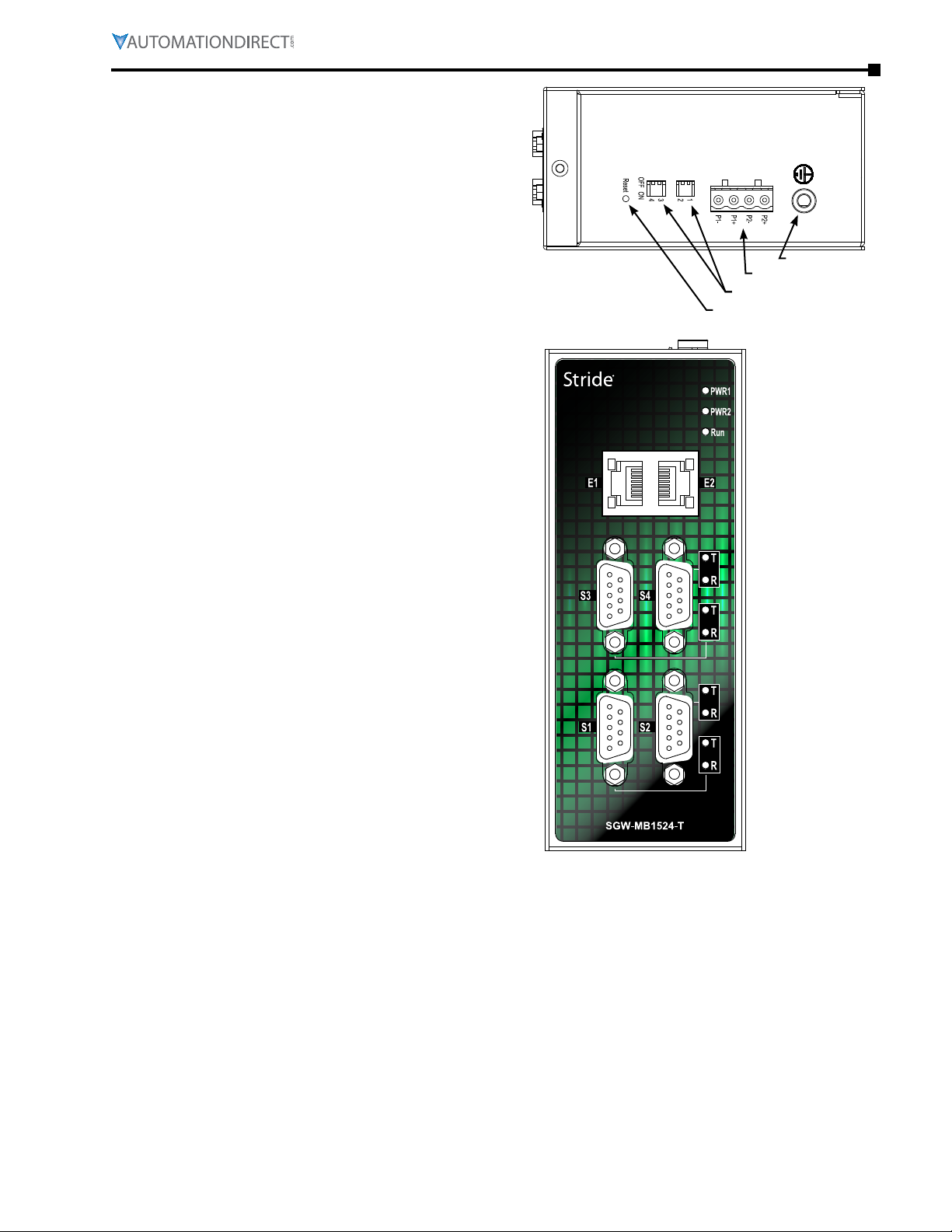
Hardware Reset Button
The Hardware Reset Button is a small
recessed button located on the top of the
device. Pressing the button will reset all
settings to their default values.
DIP Switches
Chapter 1: Getting Started
A 120Ω termination resistor for each serial
port configured for RS485 2-wire is enabled
(ON) or disabled (OFF) by the corresponding
DIP switch.
LEDs
The front panel provides status via the
following LEDs:
PWR1 (Green)
LED ON indicates voltage is applied to
Power1terminals.
PWR2 (Green)
LED ON indicates voltage is applied to
Power2terminals.
RUN (Green)
Blinking Indicates the device is functioning
normally. Steady on indicates power is on
and device is booting up.
SPEED (RJ45 Yellow)
Chassis Ground
Power Connection
Dip Switches
Hardware Reset Button
There is one yellow SPEED LED for each
Ethernet port. LED ON indicates Ethernet
speed is 100Mbps. LED OFF indicates
Ethernet speed is 10Mbps.
Link/Activity (RJ45 Green)
There is one green Link/Activity LED for each
Ethernet port. The Link/Activity LED is ON
when a valid link is established, and flashes to indicate that the gateway sees data traveling on
the Ethernet network. If any network device is sending or receiving data, the Link/Activity LED will
be flashing. During heavy communication loads, this indicator will be steady ON. If the LED is OFF,
then a problem with the Ethernet connection has been detected.
T (Serial port Transmit, Green)
The T or trAnsmit DAtA LED flashes to indicate that the gateway is sending data through the serial port.
R (Serial port Receive, Green)
The R or receive DAtA LED flashes to indicate that the gateway is receiving data through the serial port.
Page 1–5Stride® MB Gateway User Manual – 1st Edition Rev. F – April 2021
Page 16
Chapter 1: Getting Started
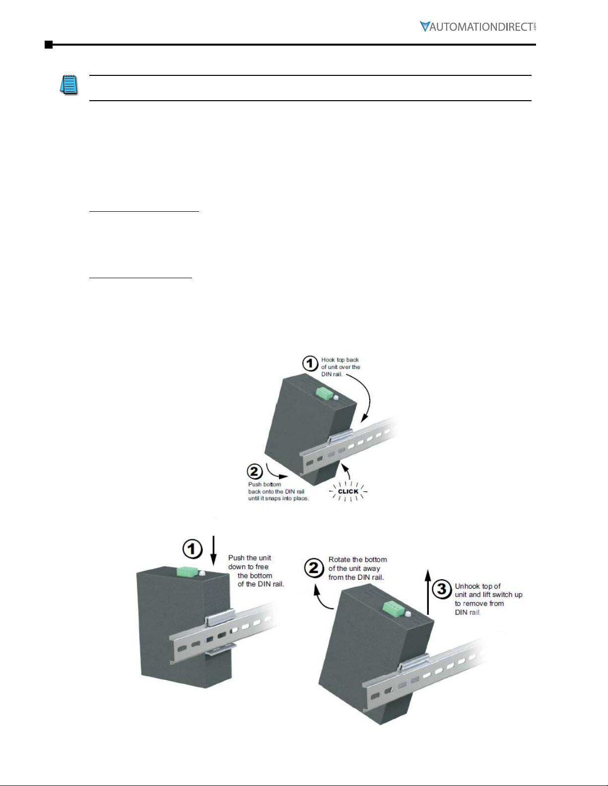
Installation, DIN Rail Mounting
NOTE: The gateway can also be panel mounted with purchase of accessory mounting bracket
(part #SE2-PM1 for SGW-MB1511-T and SGW-MB1512-T, part #SE2-PM3 for SGW-MB1524-T).
These devices are open-type and are meant to be installed in an enclosure which is only accessible
with the use of a tool and suitable for the environment when installed in Class 1, Division 2
Hazardous Locations. The gateway can be snapped onto a standard 35mm x 7.5 mm height DIN
rail (Standard: CENELEC EN50022) and can be mounted either vertically or horizontally. Allow
20mm [0.79”] of clearance between the gateway and other equipment on the DIN rail, side-to-side
and top-to-bottom.
DIN rail mounting steps:
1) Hook top back of unit over the DIN rail.
2) Push bottom back onto the DIN rail until it snaps into place.
DIN rail removal steps:
1) Push the unit down to free the bottom of the DIN rail.
2) Rotate the bottom of the unit away from the DIN rail.
3) Unhook top of unit from DIN rail.
Mounting
Removal
Page 1–6 Stride® MB Gateway User Manual – 1st Edition Rev. F – April 2021
Page 17
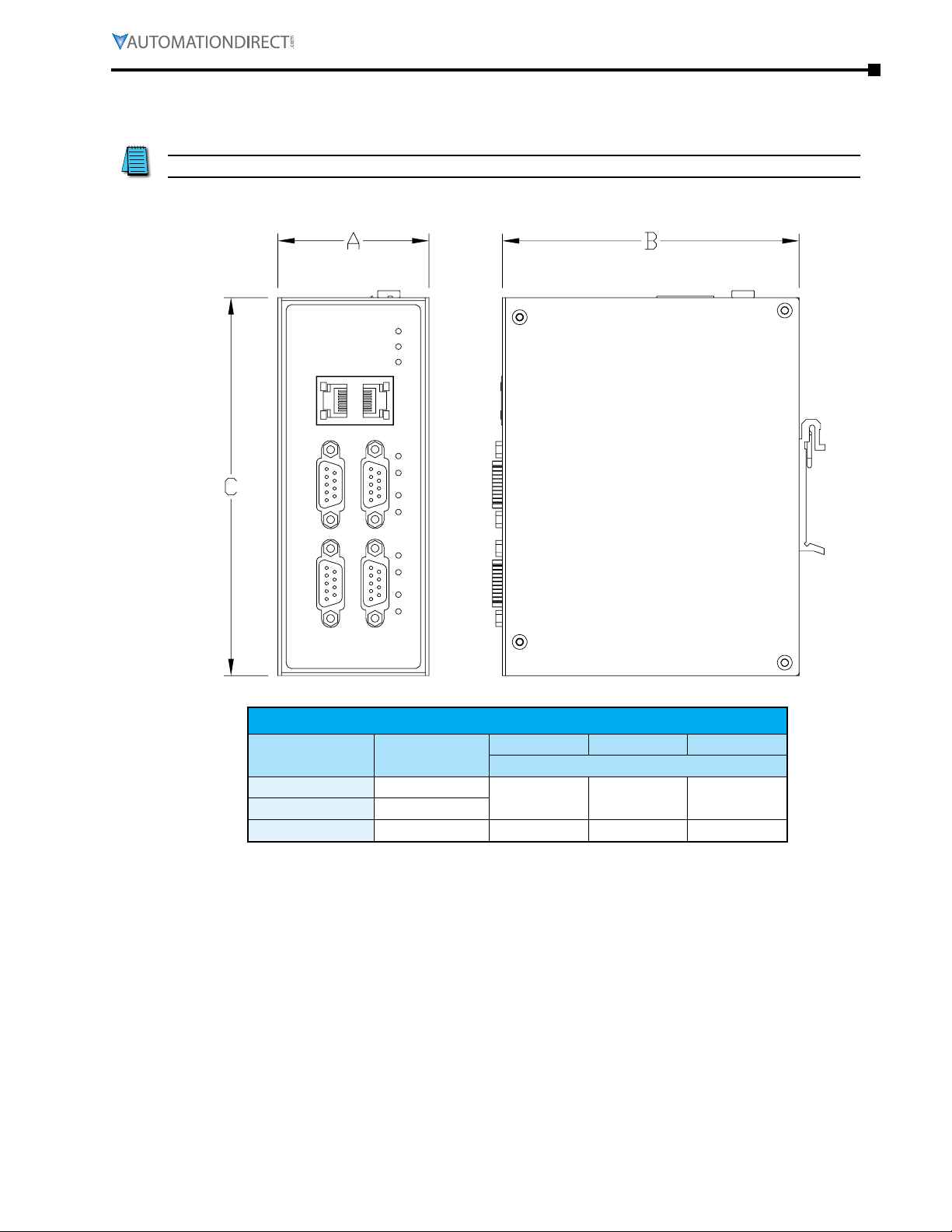
Dimensional Drawings
NOTE: Allow 20mm [0.79”] clearance around each gateway for proper cooling.
Chapter 1: Getting Started
Part No. Weight
SGW-MB1511-T
SGW-MB1512-T
SGW-MB1524-T
Dimensions
Width (A) Depth (B) Height (C)
mm [inches]
0.17 kg [0.36 lb]
0.17 kg [0.36 lb]
0.32 kg [0.71 lb] 54.0 [2.13] 106 [4.17] 135.0 [5.32]
30.0 [1.18] 68.0 [2.68] 115.0 [4.53]
Page 1–7Stride® MB Gateway User Manual – 1st Edition Rev. F – April 2021
Page 18

Chapter 1: Getting Started
Redundant DC Power
Optional Dual DC Supplies
Wiring
Power
The switch can be powered from the same DC source that is used to power your other devices. To
maintain the UL listing, this must be an SELV (Safety Extra Low Voltage) power supply. A DC voltage
in the range of 12 to 48VDC needs to be applied between the P1+ terminal and the P1- terminal
as shown below. The chassis screw terminal should be tied to panel or chassis ground. To reduce
down time resulting from power loss, the switch can be powered redundantly with a second
power supply as shown below. A recommended DC power supply is AutomationDirect.com part
number PSL-24-010.
Terminal block connector is Degson 2EDGK-5.08-04P-14-1000AH or equivalent.
Maximum terminal screw torque is
4.43 lb-in (0.5 N·m).
Ferrule required for stranded wire.
Wire Size Range: 24 – 12 AWG
Wire Strip Length: 7mm
befoRe peRfoRmING ANy WIRING to these sWItches mAke suRe...
• the AReA Is cuRReNtly NoNhAzARdous (especIAlly WheN WoRkING IN clAss 1, dIv 2 oR zoNe 2
hAzARdous locAtIoNs).
• poWeR Is off to the sWItch
• the scReW teRmINAl block Is uNpluGGed. thIs Is especIAlly ImpoRtANt due to the AlumINum
housING. coNNectING oR dIscoNNectING WIRes to the scReW block WheN It’s IN plAce ANd poWeR
Is tuRNed oN cAN AlloW the scReWdRIveR to shoRt the poWeR to the cAse.
P1+P2-P1-P2+
–
+
–
+
Chassis
GND
(panel)
Page 1–8 Stride® MB Gateway User Manual – 1st Edition Rev. F – April 2021
Page 19
Chapter 1: Getting Started
1
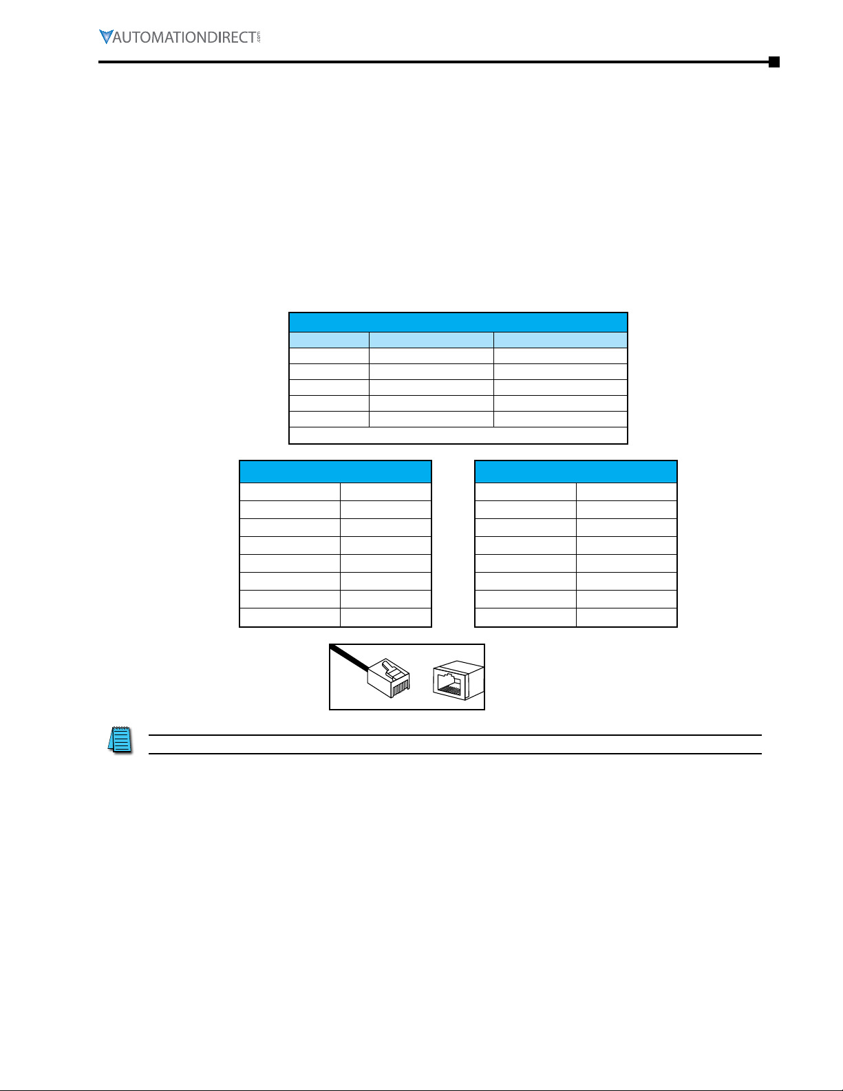
Ethernet Wiring
Use data-quality (not voice-quality) twisted pair cable rated category 5e (or better) with standard
RJ45 connectors. Straight-through or crossover Ethernet cable can be used for all devices the
switch is connected to because all the ports are capable of auto-MDI/MDIX-crossover detection.
The RJ45 Ethernet port connector bodies on these products are metallic and connected to the
Chassis GND terminal. Therefore, shielded cables may be used to provide further protection. To
prevent ground loops, the cable shield should be tied to the metal connector body at one end of
the cable only. Electrical isolation is also provided on the Ethernet ports for increased reliability.
Ethernet Cable Wiring
Ethernet Port
Pin MDI-X Signal MDI Signal
1
2
3
6
4, 5, 7, 8
Note: + and – indicate level polarities.
Receive Data + (RD+) Transmit Data + (TD+)
Receive Data – (RD–) Transmit Data – (TD–)
Transmit Data + (TD+) Receive Data + (RD+)
Transmit Data – (TD–) Receive Data – (RD–)
Unused Unused
Straight-thru Cable Wiring
Pin 1 Pin 1
Pin 2 Pin 2
Pin 3 Pin 3
Pin 4 Pin 4
Pin 5 Pin 5
Pin 6 Pin 6
Pin 7 Pin 7
Pin 8 Pin 8
8
1
NOTE: For reference only. Either cable wiring will work.
8
Cross-over Cable Wiring
Pin 1 Pin 3
Pin 2 Pin 6
Pin 3 Pin 1
Pin 4 Pin 4
Pin 5 Pin 5
Pin 6 Pin 2
Pin 7 Pin 7
Pin 8 Pin 8
Ethernet
Plug & Connector
Pin Positions
Page 1–9Stride® MB Gateway User Manual – 1st Edition Rev. F – April 2021
Page 20
Chapter 1: Getting Started
RS-232
Recommended Cable - AutomationDirect L-19772 shielded cable or equivalent
RS-422/RS-485
Gateway Slave 1Slave 2 Last Slave
Recommended C
t
RS-485
Gateway Slave 1Slave 2 Last Slave
Recommended C
t
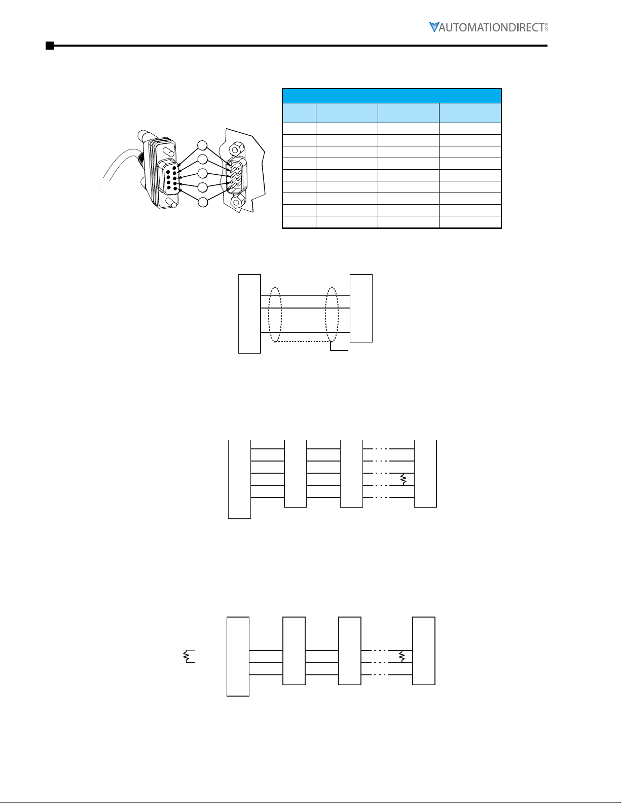
Serial Port Wiring
Serial Port Pinout
RS232 Wiring
5
4
3
2
1
Pin RS-232
1
2
3
4
5
6
7
8
9
Gateway Slave
CTS
RXD
TXD
RTS
GND
(NC)
1
2
3
4
5
6-9
Shield
Serial Port
RS-422/485
4-wire
CTS RXD – –
RXD RXD + –
TXD TXD – Data –
RTS TXD + Data +
GND GND GND
– – –
– – –
– – –
– – –
TXD
RXD
GND
GND
RS-485
2-wire
RS422/RS485 4-wire Wiring
RXDRXD+
TXDTXD+
GND
(NC)
1
2
3
4
5
6-9
able - AutomationDirect L-19773 shielded cable or equivalen
RS485 2-wire Wiring
RXDRXD+
TXDTXD+
GND
(NC)
The Gateway contains a DIP switch selectable120Ω
Termination Resistor between TXD+ and TXD- for
each serial port on RS-485 2-wire, when the
Gateway is wired at one end of the serial network.
1
2
3
4
5
6-9
able - AutomationDirect L-19954 shielded cable or equivalen
TDTD+
RDRD+
GND
DD+
GND
TD-
TD+
RD-
RD+
GND
DD+
GND
TDTD+
RD-
*
RD+
GND
* User Supplied
120Ω Termination
Resistor
D-
*
D+
GND
* User Supplied
120Ω Termination
Resistor
Page 1–10 Stride® MB Gateway User Manual – 1st Edition Rev. F – April 2021
Page 21

Operation
Client
Slave
Server
Master
Client
Slave
Server
Master
The STRIDE® Modbus Gateway may be configured to function in Transparent Mode or Agent Mode.
Transparent Mode is a simple protocol bridge. Modbus TCP packets that arrive at the gateway
Ethernet port will be translated to Modbus RTU or Modbus ASCII and transmitted out the
appropriate serial port. Likewise, communications arriving at the serial port will be translated to
Modbus TCP and transmitted out the Ethernet port. Data simply passes across the gateway.
Agent Mode is a valuable feature of the STRIDE® Modbus Gateway. The Agent can be configured
to poll specific Modbus data addresses at the serial or Ethernet nodes and store that data into
gateway shared memory. If a Modbus query comes in for one of those data points, the gateway
will immediately respond with the data it has stored and thereby respond much faster than it
would if it had to forward that request and wait for the response.
Transparent Mode
Chapter 1: Getting Started
Modbus query
Modbus response
Agent Mode
TCP
TCP
Gateway
Server
Gateway
Cached
data
RTU or ASCII
Modbus query
Master
Modbus response
RTU or ASCII
Modbus query
Modbus response
Modbus query
Gateway
Client
RTU or ASCII
Modbus query
Slave
Modbus response
OR
TCP
Modbus query
Modbus response
TCP
Modbus query
Modbus response
Gateway
Cached
data
RTU or ASCII
Modbus query
Gateway responds
with cached data
Server
Modbus response
Modbus query
Master
Modbus response
Modbus query
OR
Modbus response
Modbus query
Modbus response
Client
Modbus query
Gateway responds
with cached data
Slave
Page 1–11Stride® MB Gateway User Manual – 1st Edition Rev. F – April 2021
Page 22

Chapter 1: Getting Started
Page 1–12 Stride® MB Gateway User Manual – 1st Edition Rev. F – April 2021
Page 23

Chapter
Chapter
Chapter
Summary of modbuS modeS
2
2
2
in t
hiS Chapter
Introduction � � � � � � � � � � � � � � � � � � � � � � � � � � � � � � � � � � � � � � � � � � � � � � �2–2
Mode 1: Transparent, RTU Master mode:
Modbus TCP Client/Master Device to Gateway to Modbus RTU Slave Devices � � � � � � � � � �2–3
Mode 2: Agent, RTU Master mode:
Modbus TCP Client/Master Device to Gateway Memory� Gateway Talks Directly to Modbus RTU
Slave Devices� � � � � � � � � � � � � � � � � � � � � � � � � � � � � � � � � � � � � � � � � � � � � � �2–4
Mode 3: Transparent, RTU Slave mode:
Modbus RTU Master Device to Gateway to Modbus TCP Server/Slave Devices � � � � � � � � � �2–6
Mode 4: Agent, RTU Slave mode:
Modbus RTU Master Device to Gateway Memory� Gateway Talks Directly to Modbus TCP Server/
Slave Devices� � � � � � � � � � � � � � � � � � � � � � � � � � � � � � � � � � � � � � � � � � � � � � �2–7
...
Page 2–1Stride® MB Gateway User Manual – 1st Edition Rev. F – April 2021
Page 24

Chapter 2: Summary of Modbus Modes
Introduction
As mentioned in the previous chapter, the STRIDE® Modbus Gateway may be configured to operate
in four distinct modes:
• Mode 1: Transparent mode, with serial port functioning as a master device
• Mode 2: Agent mode, with serial port functioning as a master device
• Mode 3: Transparent mode, with serial port functioning as a slave device
• Mode 4: Agent mode, with serial port functioning as a slave device
Operation under each of the four modes is discussed in this chapter. For simplicity, the discussion
uses RTU protocol for the serial port. The operations would be essentially identical if the serial
port used ASCII protocol.
Page 2–2 Stride® MB Gateway User Manual – 1st Edition Rev. F – April 2021
Page 25
Chapter 2: Summary of Modbus Modes
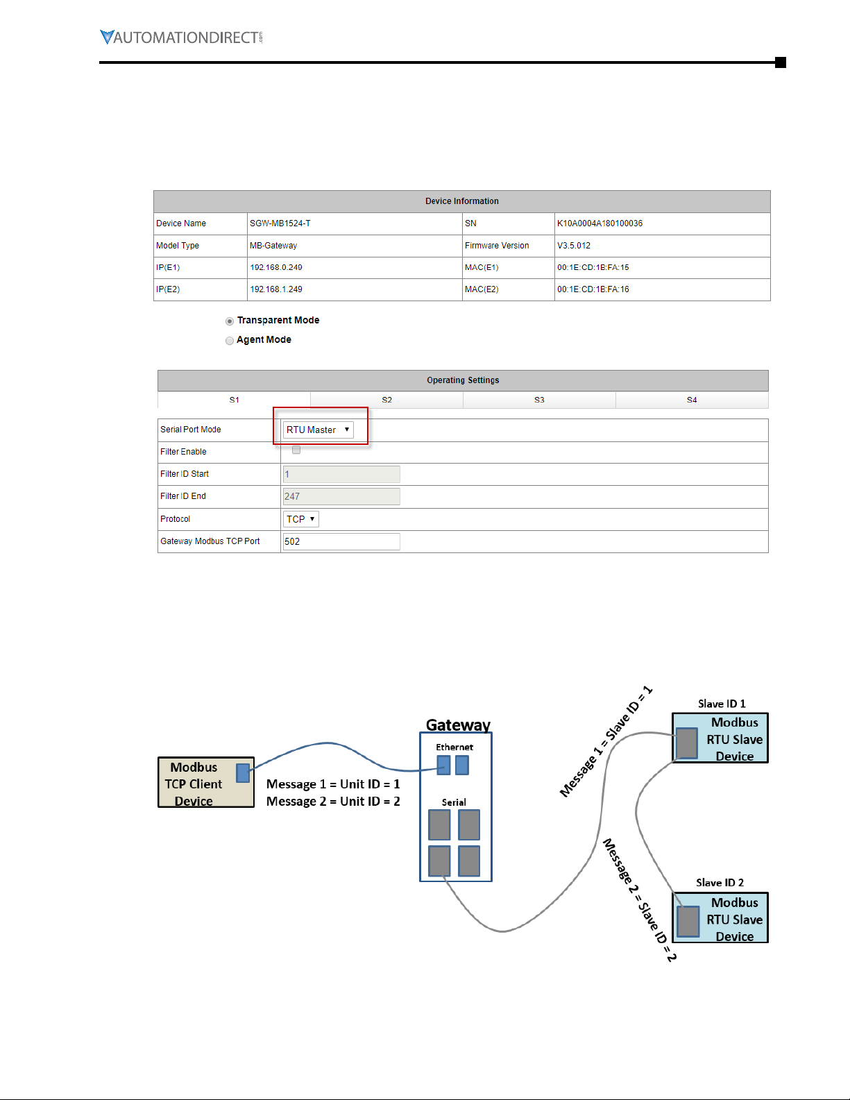
Mode 1: Transparent, RTU Master mode: Modbus TCP Client/Master Device to Gateway to Modbus RTU Slave Devices
In this mode, the Current Working Mode is set to “Transparent” and the Serial Port Mode is set to
“RTU Master”. These settings are displayed on the Device Information page and Operating Settings
page of the web interface, respectively, as shown below.
A typical network using the gateway to connect a Modbus TCP client device to multiple Modbus
RTU slave devices is illustrated below. The Modbus messages are simply translated in the gateway
from Modbus TCP framing to Modbus RTU framing and then sent on to the serial network.
Addressing a specific slave device is handled by the Unit Identifier (Slave ID) contained in the
Modbus message.
Page 2–3Stride® MB Gateway User Manual – 1st Edition Rev. F – April 2021
Page 26

Chapter 2: Summary of Modbus Modes
Mode 2: Agent, RTU Master mode: Modbus TCP Client/Master Device to Gateway Memory. Gateway Talks Directly to Modbus RTU Slave Devices
In this mode, the Current Working Mode is set to “Agent” and the Serial Port Mode is set to “RTU
Master”. These settings are displayed on the Device Information page and Operating Settings page
of the web interface, respectively, as shown below.
In Agent mode, the gateway must be assigned a Modbus ID, as shown below, since the Modbus
TCP Client will query the gateway memory using that Unit ID rather than querying the slave
devices directly.
Page 2–4 Stride® MB Gateway User Manual – 1st Edition Rev. F – April 2021
Page 27
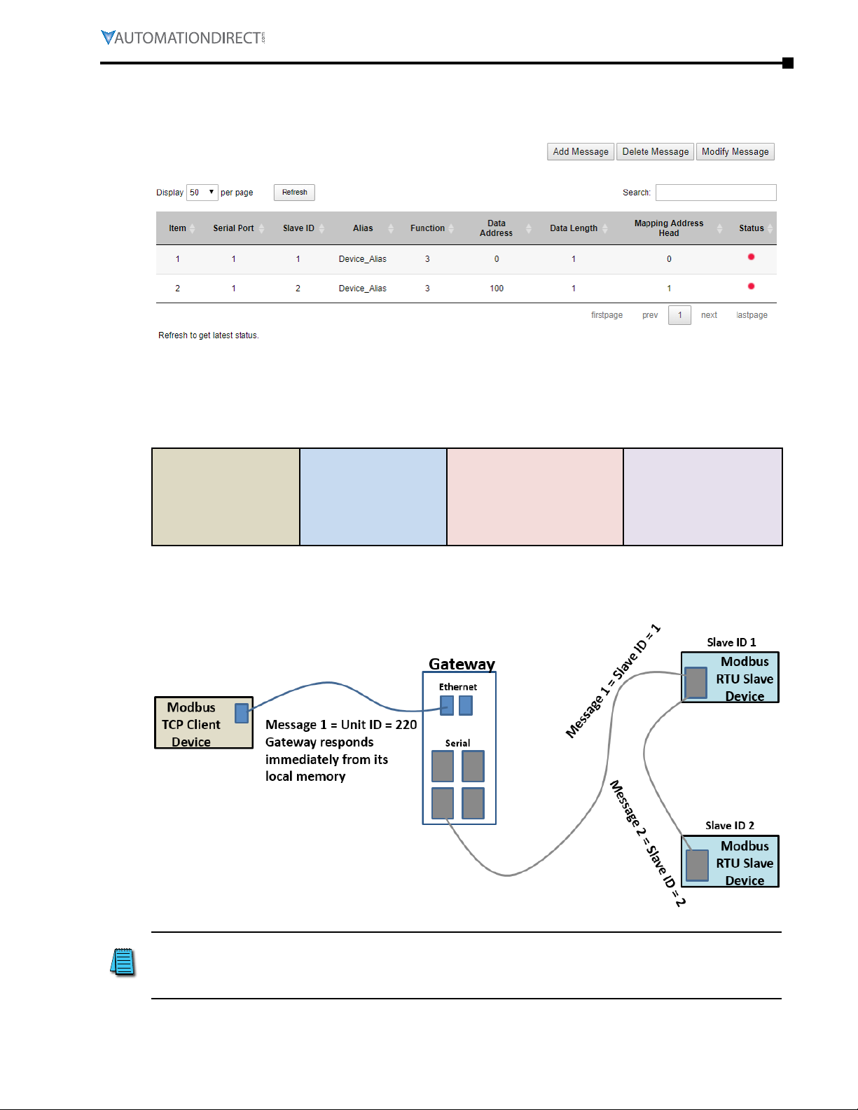
Chapter 2: Summary of Modbus Modes
A list of messages must be created defining the data to be collected from various RTU slave
devices connected to the serial port, and the addresses within the gateway at which to store the
collected data.
In Agent mode, the Gateway sends messages created by the Slave list to the Modbus RTU slave
devices. The response data from these messages are stored in local memory of the Gateway
for access by the Modbus TCP Client device. The data is stored in 4 different memory blocks
depending upon the Function Code used.
Coils (0x)
Data stored from
Function Code 1
The Gateway generates the serial messages from the slave list items. It stores the data from the
responses in its local memory that is available to Modbus TCP devices. Modbus TCP client devices
query the gateway using its Unit ID, and the gateway responds immediately with its cached data.
Inputs (1x)
Data stored from
Function Code 2
Holding Registers (4x)
Data stored from
Function Code 3
Input Registers (3x)
Data stored from
Function Code 4
NOTE: Modbus writes sent from the Modbus TCP client go across directly to the Modbus RTU
slave devices as if the gateway were in Transparent mode. When the gateway is in Agent mode,
addresses that devices will use to WRITE data into must be configured in the Message List even
though conceptually this is a list of data that is READ from connected devices.
Page 2–5Stride® MB Gateway User Manual – 1st Edition Rev. F – April 2021
Page 28
Chapter 2: Summary of Modbus Modes
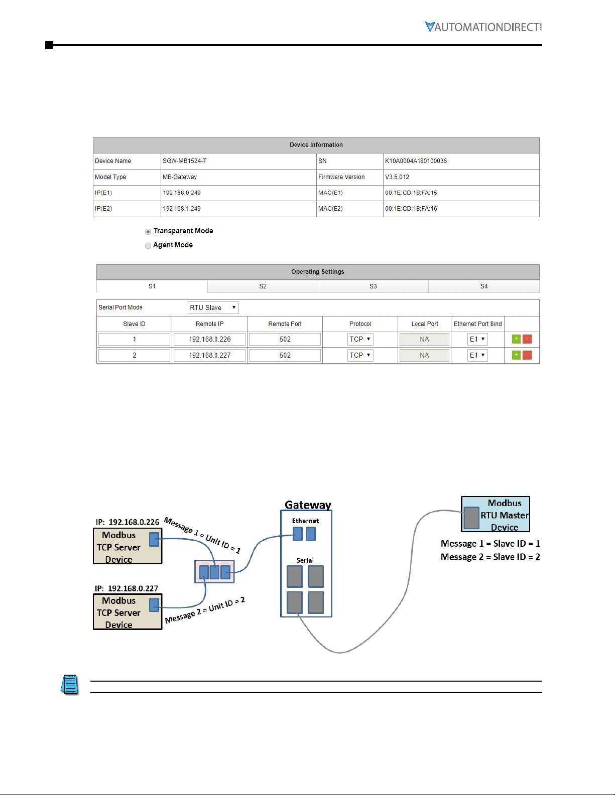
Mode 3: Transparent, RTU Slave mode: Modbus RTU Master Device to Gateway to Modbus TCP Server/Slave Devices
In this mode, the Current Working Mode is set to “Transparent” and the Serial Port Mode is set to
“RTU Slave”. These settings are displayed on the Device Information page and Operating Settings
page of the web interface, respectively, as shown below.
In RTU Slave mode, each TCP server device must be configured in the gateway with an IP address,
remote port, and Unit ID (Slave ID). A unique local port is set only when the protocol is UDP.
A typical network using the gateway to connect a Modbus RTU master device to multiple Modbus
TCP server devices is illustrated below. The gateway reads the Slave ID from the message of the
Modbus RTU master device and does a lookup in the table to find the target IP address. It also
places the Slave ID value into the Unit ID field of the Modbus TCP frame.
NOTE: Remember that only one master may be connected to each serial port.
Page 2–6 Stride® MB Gateway User Manual – 1st Edition Rev. F – April 2021
Page 29

Chapter 2: Summary of Modbus Modes
Mode 4: Agent, RTU Slave mode: Modbus RTU Master Device to Gateway Memory. Gateway Talks Directly to Modbus TCP Server/Slave Devices
In this mode, the Current Working Mode is set to “Agent” and the Serial Port Mode is set to “RTU
Slave”. These settings are displayed on the Device Information page and Operating Settings page
of the web interface, respectively, as shown below.
In Agent mode, the gateway must be assigned a Modbus ID, as shown below, since the Modbus
RTU Master will query the gateway memory using that Unit ID rather than querying the slave
devices directly.
Page 2–7Stride® MB Gateway User Manual – 1st Edition Rev. F – April 2021
Page 30

Chapter 2: Summary of Modbus Modes
A list of messages must be created defining the data to be collected from various TCP server
devices connected to the Ethernet port specified in the Operating Settings, and the addresses
within the gateway at which to store the collected data.
In Agent mode, the Gateway sends messages created by the Slave list to the Modbus TCP server
devices. The response data from these messages are stored in local memory of the Gateway for
access by the RTU master device. The data is stored in 4 different memory blocks depending upon
the Function Code used.
Coils (0x)
Data stored from
Function Code 1
The Gateway generates the Modbus TCP messages from the Slave list items. It must first reference
the table in the Operating settings to do a lookup from the Slave ID of the Slave list message to
find the corresponding IP address. It stores the data from the responses in its local memory that
is available to Modbus RTU devices. The Modbus RTU master device queries the gateway using its
Unit ID, and the gateway responds immediately with its cached data.
Inputs (1x)
Data stored from
Function Code 2
Holding Registers (4x)
Data stored from
Function Code 3
Input Registers (3x)
Data stored from
Function Code 4
NOTE: Modbus writes sent from the Modbus RTU master go across directly to the Modbus TCP
server devices as if the gateway were in Transparent mode. When the gateway is in Agent mode,
addresses that devices will use to WRITE data into must be configured in the Message List even
though conceptually this is a list of data that is READ from connected devices.
Page 2–8 Stride® MB Gateway User Manual – 1st Edition Rev. F – April 2021
Page 31

Chapter
Chapter
Chapter
Web Console Configuration
3
3
3
in t
hiS Chapter
Initial Connection � � � � � � � � � � � � � � � � � � � � � � � � � � � � � � � � � � � � � � � � � � � � 3-2
Device Info Page� � � � � � � � � � � � � � � � � � � � � � � � � � � � � � � � � � � � � � � � � � � � � 3-3
Network Settings � � � � � � � � � � � � � � � � � � � � � � � � � � � � � � � � � � � � � � � � � � � � 3-4
Operating Settings � � � � � � � � � � � � � � � � � � � � � � � � � � � � � � � � � � � � � � � � � � � 3-5
For Modbus RTU/ASCII Master to Modbus TCP Servers (Slaves) � � � � � � � � � � � � � � � � � � � � � 3-5
For Modbus TCP Master (Client) Device to Modbus RTU/ASCII Slave Devices � � � � � � � � � � � � � � 3-6
Serial Settings � � � � � � � � � � � � � � � � � � � � � � � � � � � � � � � � � � � � � � � � � � � � � � 3-7
Agent Settings � � � � � � � � � � � � � � � � � � � � � � � � � � � � � � � � � � � � � � � � � � � � � � 3-8
Gateway Settings � � � � � � � � � � � � � � � � � � � � � � � � � � � � � � � � � � � � � � � � � � � � � � � 3-8
Message List � � � � � � � � � � � � � � � � � � � � � � � � � � � � � � � � � � � � � � � � � � � � � � � � � � 3-9
Data in Gateway Memory � � � � � � � � � � � � � � � � � � � � � � � � � � � � � � � � � � � � � � � � � � � 3-11
Import/Export � � � � � � � � � � � � � � � � � � � � � � � � � � � � � � � � � � � � � � � � � � � � � 3-12
Export� � � � � � � � � � � � � � � � � � � � � � � � � � � � � � � � � � � � � � � � � � � � � � � � � � � � � � 3-12
Import � � � � � � � � � � � � � � � � � � � � � � � � � � � � � � � � � � � � � � � � � � � � � � � � � � � � � 3-12
Upgrade Firmware� � � � � � � � � � � � � � � � � � � � � � � � � � � � � � � � � � � � � � � � � � � 3-13
Change Password � � � � � � � � � � � � � � � � � � � � � � � � � � � � � � � � � � � � � � � � � � � 3-14
Load Factory Default � � � � � � � � � � � � � � � � � � � � � � � � � � � � � � � � � � � � � � � � � 3-15
Reboot � � � � � � � � � � � � � � � � � � � � � � � � � � � � � � � � � � � � � � � � � � � � � � � � � 3-16
...
Page 3-1Stride® MB Gateway User Manual – 1st Edition Rev. F – April 2021
Page 32
Chapter 3: Device Configuration
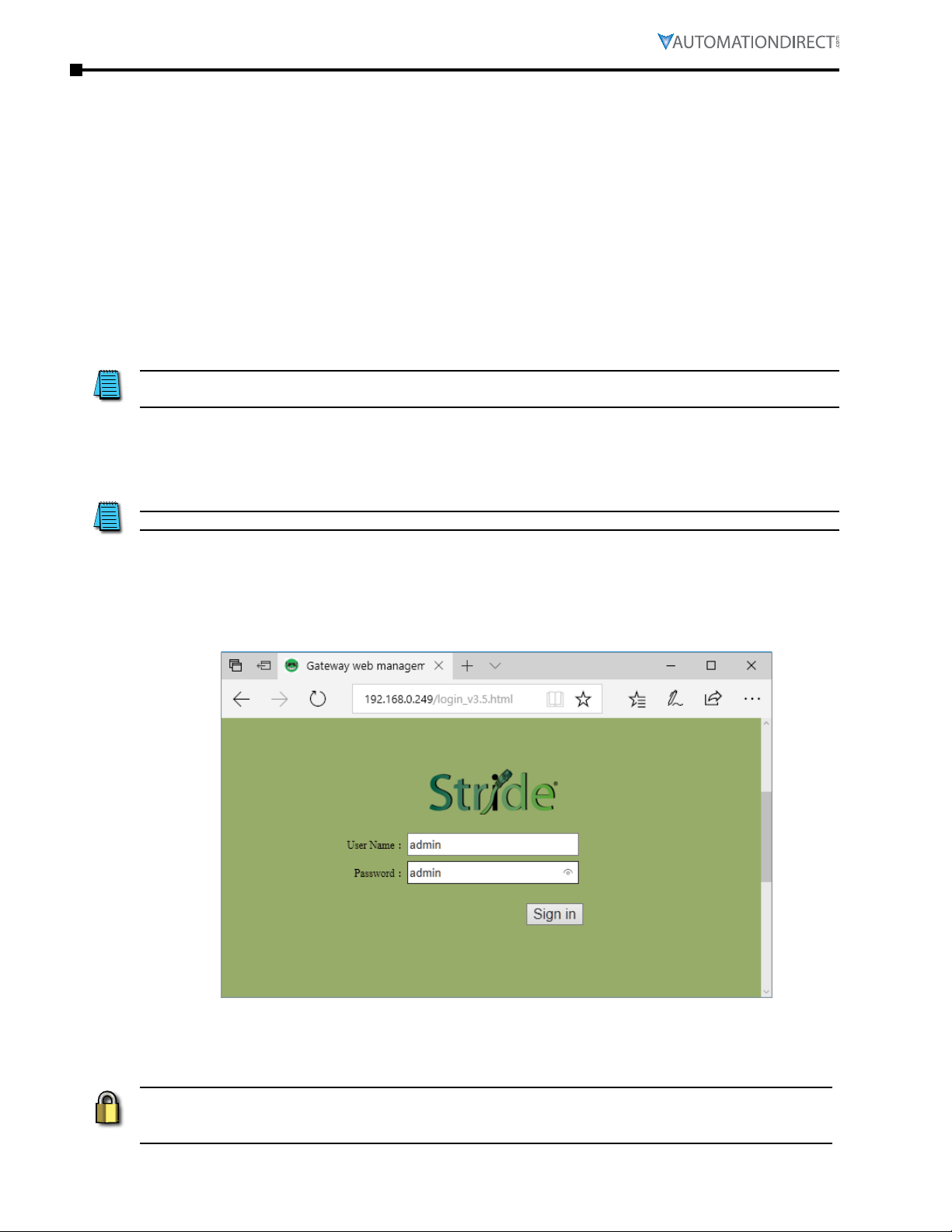
Initial Connection
The gateway is configured through a web console, which is accessed using any web browser.
The default management interface access is:
• IP address: 192.168.0.249 (if connecting at port E1)
or 192.168.1.249 (if connecting at port E2)
• Port: 80
• Username: admin
• Password: admin
NOTE: SGW-MB1511-T and SGW-MB1512-T have one Ethernet port (E1); SGW-MB1524-T has two
Ethernet ports (E1 & E2).
For initial setup, the PC used to connect to the STRIDE® Modbus Gateway must have an IP address
that allows it to connect to the device’s default IP address. The Modbus gateway’s IP address can
be changed later within the web console.
NOTE: The Modbus gateway’s web console supports the latest version of all modern browsers.
In your browser, type the gateway’s IP address (192.168.0.249 or 192.168.1.249) in the address field
and press Enter. When prompted by a dialog box, enter the default Username and Password.
After logging in, you will be presented with the device’s overview page.
SECURITY NOTE: We recommend that you change the login password and enable HTTPS ecryption
for additional security. These settings are found on the Change Password page as described later
in this chapter.
Page 3-2 Stride® MB Gateway User Manual – 1st Edition Rev. F – April 2021
Page 33
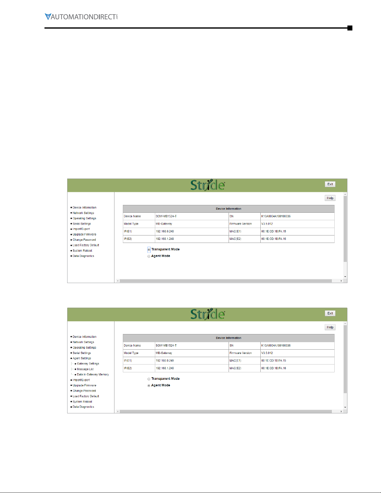
Device Info Page
The Device Information page displays a summary of information to identify the gateway.
The device name is configured on the Network Settings page. The device name helps users
distinguish between multiple gateways.
The serial number (“SN”), model type and MAC address(es) are not configurable. These are
characteristics of the individual gateway and may help distinguish between multiple gateways.
The values that display on this page may be compared to the values printed on the device label.
The IP address(es) are configured on the Network Settings page. IP addresses must be unique on
the network.
You can switch the device between Agent mode and Transparent mode by clicking the “Agent
Mode” (or “Transparent Mode”) button. The button toggles the gateway immediately between
the two operating modes without requiring further confirmation. The menu in the left column will
update to reflect options relevant to the current mode of operation.
Device Info screen with gateway in Transparent mode:
Chapter 3: Device Configuration
Device Info screen with gateway in Agent mode:
Page 3-3Stride® MB Gateway User Manual – 1st Edition Rev. F – April 2021
Page 34
Chapter 3: Device Configuration
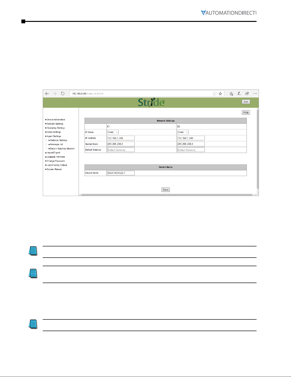
Network Settings
The Network Settings page allows selection between DHCP and static network settings for the
Ethernet port(s), with the following requirements:
•
IP addresses must be unique on the network�
•
On models with two Ethernet ports, the two ports may be configured on the same subnet or
different subnets�
•
A Default Gateway must be configured if any devices will be configured as Modbus TCP servers
on a subnet different than that of the STRIDE gateway Ethernet port�
Click Save to save the current changes to the unit before leaving this screen.
Default Network Settings:
•
IP configuration: Static
•
IP address: E1 – 192�168�0�249; E2 – 192�168�1�249
•
Subnet Mask: 255�255�255�0
•
Default Gateway: no value
NOTE: SGW-MB1511-T and SGW-MB1512-T have one Ethernet port; SGW-MB1524-T has two Ethernet
ports.
NOTE: You may lose communications with the STRIDE Gateway module if you configure an IP
address and/or Subnet Mask that is not compatible with the subnet of your PC’s Network Interface
Card. You may be required to change the subnet settings of your PC.
Device Name:
•
The default gateway name is the model number� You can set the name, limited to 16 alphanumeric
characters or special characters dash ( - ) or underline ( _ )� The gateway name is used for
reference and identification when managing several different gateway modules on a network�
NOTE: Remember to click the SAVE button before you leave this page. Leaving the page before
saving changes will cancel changes.
Page 3-4 Stride® MB Gateway User Manual – 1st Edition Rev. F – April 2021
Page 35
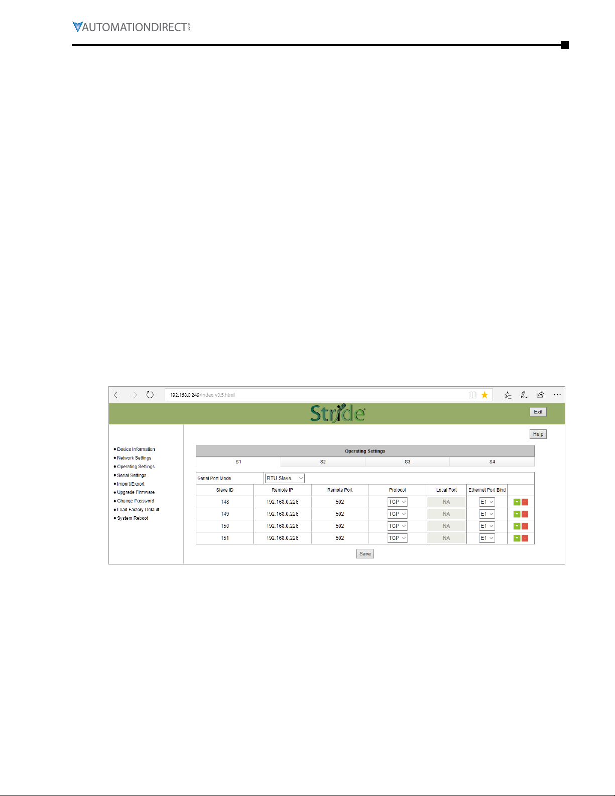
Operating Settings
The Operating Settings page is where each serial interface’s operation mode is configured.
The Serial Port Mode field describes the function of each serial port on the Gateway.
Each serial port can independently function as a master (communicating with up to 128 serial slave
devices) or as a slave (communicating with a serial master device), using either RTU or ASCII protocols.
The Operating Settings page exposes different settings depending on whether each port is operating
as a master (with Modbus TCP master device (client) and Modbus RTU/ASCII slave devices) or as a
slave (with a Modbus RTU/ASCII master device and Modbus TCP slave devices (servers)).
For Modbus RTU/ASCII Master to Modbus TCP Servers (Slaves)
To connect a Modbus RTU or ASCII master device to one or more Modbus TCP server (slave)
devices, the gateway serial port will function as an ASCII or RTU slave.
Up to 16 Modbus TCP server devices can be configured. Devices can be added or removed from
the list using the green + or red - buttons, respectively. The Slave ID, IP address and remote port
of each Modbus TCP server device on the Ethernet ports must be configured. Additionally, the
Ethernet protocol, TCP or UDP, of each Modbus TCP server device must be configured. A Default
Gateway must be configured on the Network Settings page if any devices will be configured as
Modbus TCP servers on a subnet different than that of the STRIDE Gateway Ethernet port.
Chapter 3: Device Configuration
For SGW-MB1524-T, which has two Ethernet ports, when the gateway’s serial port is operating as
an RTU or ASCII slave the Ethernet port through which each TCP server can be reached must be
selected in the Ethernet Port Bind field.
Gateway Operating Settings:
•
Serial Port Mode: RTU Slave or ASCII Slave
•
Slave ID: set the ID to match each Modbus TCP server (slave)
•
Remote IP: enter the IP address of each Modbus TCP server (slave)� A Default Gateway must be
configured on the Network Settings page if any devices will be configured as Modbus TCP servers
on a subnet different than that of the STRIDE gateway Ethernet port�
•
Remote Port: enter the port number for each Modbus TCP server (slave)� Each server must have a
unique port number� This is a TCP or UDP port that will identify the server in the Modbus TCP packet�
•
Protocol: select TCP or UDP
•
Local Port: For UDP, this is the source port that will identify communication traffic for each slave
ID� For TCP traffic the source port is automatically determined�
Page 3-5Stride® MB Gateway User Manual – 1st Edition Rev. F – April 2021
Page 36
Chapter 3: Device Configuration
•
Ethernet Port Bind: select Ethernet port E1 or E2 (model SGW-MB1524-T only)� The Ethernet Port
Bind is used by the Gateway when the Modbus TCP device IP address is not on the same subnet
as the Gateway IP address�
NOTE: Remember to click the SAVE button before you leave this page or switch to another serial port
tab. Leaving the page or selecting another serial port before saving changes will cancel changes.
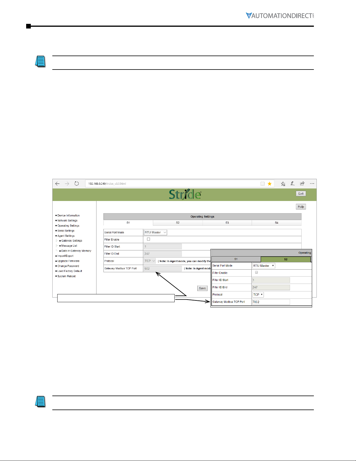
For Modbus TCP Master (Client) Device to Modbus RTU/ASCII Slave Devices
To connect a Modbus TCP client (master) device to one or more Modbus RTU or ASCII slave
devices, the gateway serial port will function as an ASCII or RTU master.
In that case, the Ethernet Protocol (TCP or UDP) and Gateway Modbus TCP Port to associate with
the serial port must be configured. When multiple serial ports are set as RTU Masters, a unique
Gateway Modbus TCP port must be assigned to each serial port in order to differentiate the
serial networks. For SGW-MB1524-T, a Modbus TCP client attached to either Ethernet port can
communicate to RTU/ASCII slaves on the serial port using the configured Modbus TCP Port.
The Filter option will eliminate Slave ID numbers from the processed traffic when enabled. To
enable the filter feature, check the Filter Enable box and enter the starting number and ending
number of the nodes that should never appear in messages that will be processed.
Each serial port’s TCP port must be unique.
Gateway Operating Settings:
•
Serial Port Mode: RTU Master or ASCII Master
•
Filter Enable: eliminate a range of Slave IDs from communication
•
Filter ID Start: set lowest Modbus Slave ID to ignore (0-247, must be ≤ Filter ID End)
•
Filter ID End: set highest Modbus Slave ID to ignore (0-247, must be ≥ Filter ID Start)
•
Protocol: select TCP or UDP (When the Modbus Gateway is in Agent Mode, the protocol is set on
the Gateway Settings page�)
•
Gateway Modbus TCP Port: set the TCP port number to communicate with RTU/ASCII slaves on
this serial port� (When the Modbus Gateway is in Agent Mode, the Gateway Modbus TCP Port is
set on the Gateway Settings page�)
NOTE: Remember to click the SAVE button before you leave this page or switch to another serial port
tab. Leaving the page or selecting another serial port before saving changes will cancel changes.
Page 3-6 Stride® MB Gateway User Manual – 1st Edition Rev. F – April 2021
Page 37
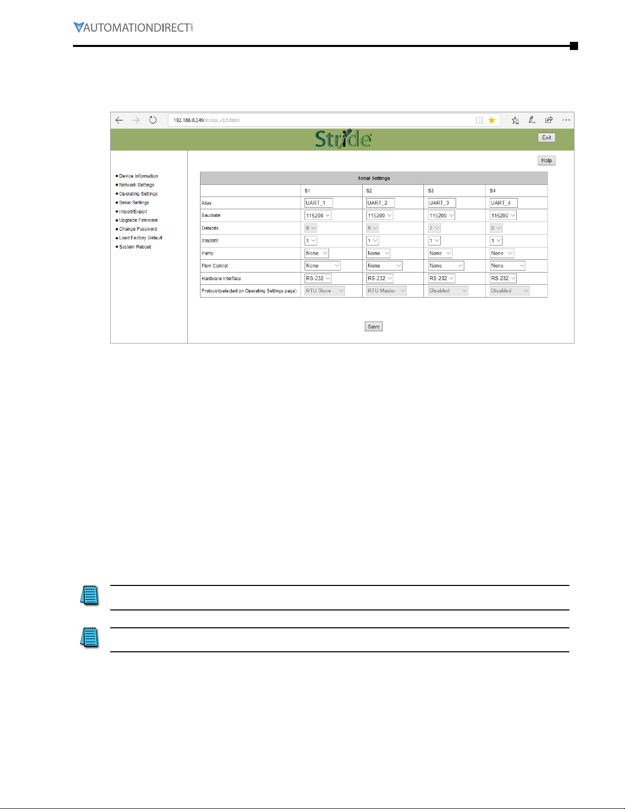
Serial Settings
The Serial Setting page is where each serial port’s communication parameters are configured.
Chapter 3: Device Configuration
Serial Parameters:
•
Alias: serial port alias name� This is a convenience for your reference�
The following settings must match the settings in all connected devices:
•
Baudrate: 300–460800bps, the default value is 115200bps
•
Databits: 7 or 8 bits� The value is locked to 8 bits for RTU or 7 bits for ASCII serial modes�
•
Stopbits: 1 or 2, the default value is 1
•
Parity: Odd, Even or None, the default value is None
•
Flow Control: RTS/CTS, XON/XOFF or None; the default value is None
•
Hardware Interface: RS-232, RS-485 or RS-422; the default value is RS-232
•
Protocol (selected on Operating Settings Page): RTU Slave, ASCII Slave, RTU Master, ASCII Master
NOTE: In some situations, such as a high amount of electrical noise, poor cabling, etc., it may be
necessary to reduce the baud rate on the gateway module AND serial devices on the network.
NOTE: Remember to click the SAVE button before you leave this page. Leaving the page before
saving changes will cancel changes..
Page 3-7Stride® MB Gateway User Manual – 1st Edition Rev. F – April 2021
Page 38
Chapter 3: Device Configuration
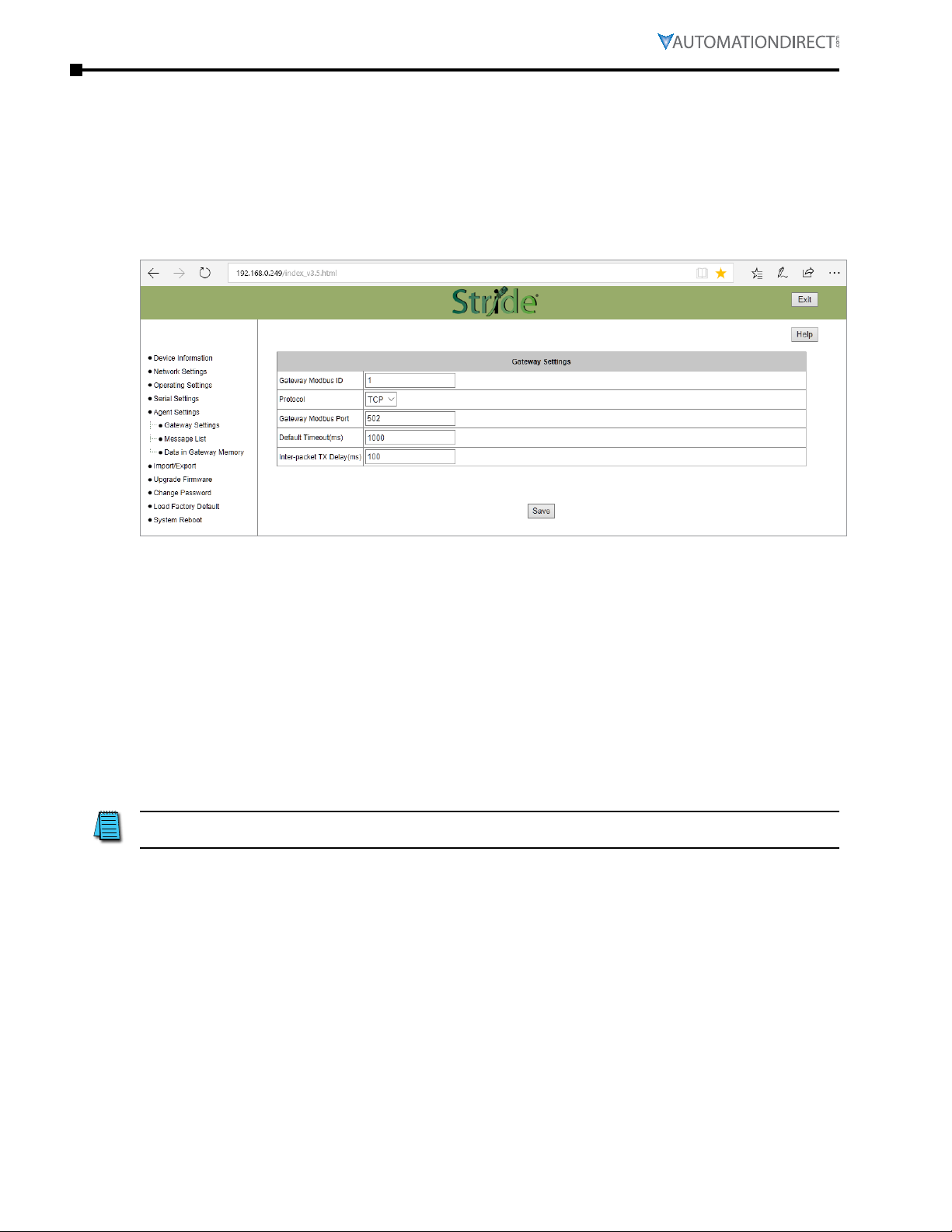
Agent Settings
The pages grouped in the navigation tree under Agent Settings configure the gateway to work in
Agent mode, and are visible only when that mode is selected.
Gateway Settings
Configure the gateway Modbus ID, timeout, and inter-packet transmit delay.
Gateway Settings:
•
Gateway Modbus ID: Unique Modbus ID assigned to the gateway to allow clients to request data
from the gateway’s local cache, 1–247�
•
Protocol: TCP or UDP�
•
Gateway Modbus Port: set the TCP port number to communicate with RTU/ASCII slaves on this
serial port�
•
Default timeout (ms): default timeout before retrying a data request; default is 1000ms�
•
Interpacket TX delay (ms): Poll Time setting for the delay between requests polling slave devices
to populate local cache; default is 100ms�
NOTE: Remember to click the SAVE button before you leave this page. Leaving the page before
saving changes will cancel changes.
Page 3-8 Stride® MB Gateway User Manual – 1st Edition Rev. F – April 2021
Page 39
Chapter 3: Device Configuration
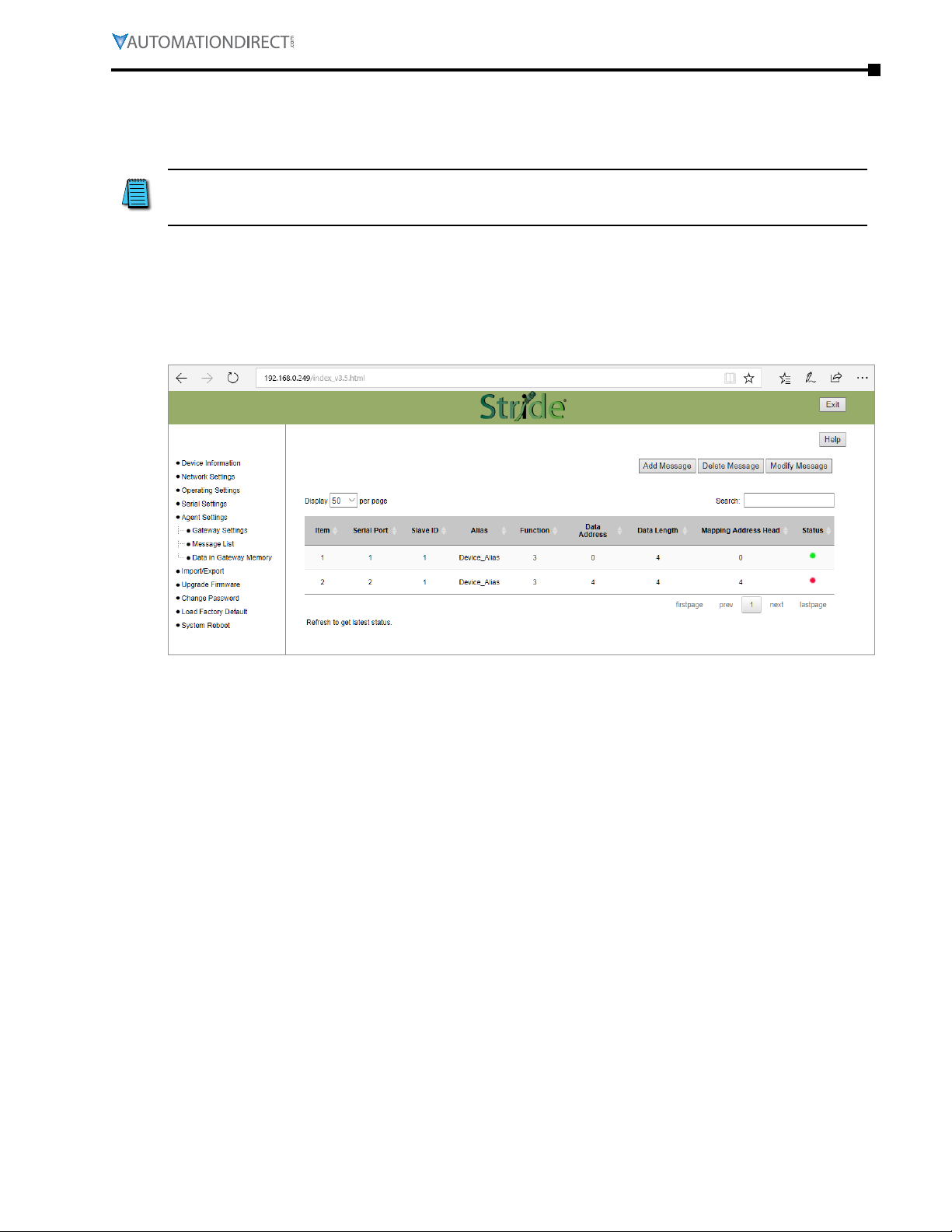
Message List
The Message List page displays a table that summarizes the data stored locally in the gateway’s
memory. Modbus client devices may request this data from the gateway’s local cache.
NOTE: When the gateway is in Agent mode, addresses that devices will use to WRITE data into
must be configured in the Message List even though conceptually this is a list of data that is READ
from connected devices.
Configure and manage the message request list. A summary of configured messages is displayed,
which can be filtered to display a subset of the list using the “Search” field.
From this page, messages can be added, deleted or modified.
Each parameter of the Message List is explained in the Add Message section to follow.
A green dot in the Status column indicates that the message is successfully connected to its target
device. A red dot indicates that it is not successfully connected. The web page must be manually
refreshed to update the status indicator.
Page 3-9Stride® MB Gateway User Manual – 1st Edition Rev. F – April 2021
Page 40
Chapter 3: Device Configuration
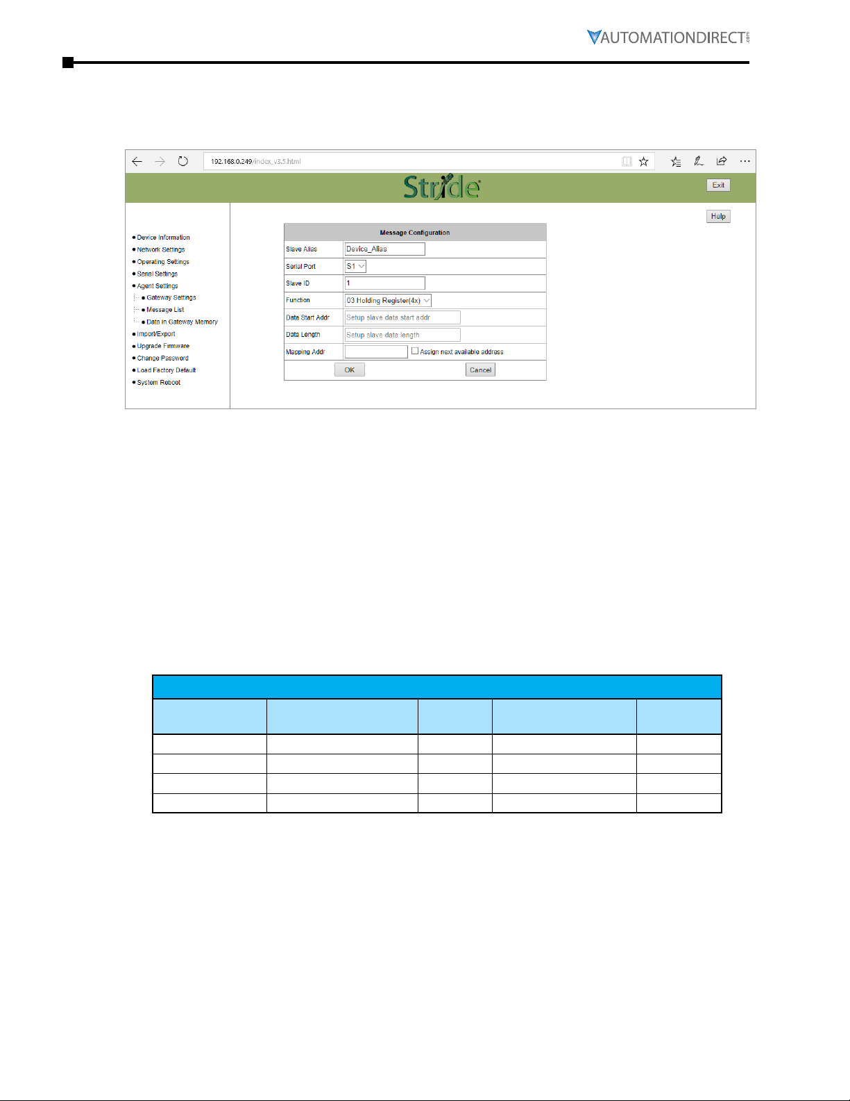
Add Message
Clicking the “Add Message” button brings up a Message Configuration dialog box to configure a
new message.
Add New Message Settings:
•
Slave alias: name for each device to help users recognize it more easily
•
Serial port: the gateway serial port number to which the device is attached
•
Slave ID: the device’s Modbus node ID on the communication network
•
Function: the Modbus protocol function code� Function codes are listed in the table below�
•
Data Start Address: the address in the target device from which the gateway will read the data
•
Data Length: the data block size the gateway will read
•
Mapping Address: the location in the gateway’s shared memory (cached data) from which the
data will be retrieved when a Modbus TCP query is received� Ensure that this memory block does
not overwrite a block configured for another message�
•
Assign next available address: conveniently assigns the next available address to this request, to
ensure data blocks do not overlap (overwrite)�
Modbus Functions
Modbus Function
Code
1 Read Coil 0-65535 0001-065536 1-2000
2 Read Discrete Input 0-65535 100001-165536 1-2000
3 Read Holding Registers 0-65535 400001-465536 1-125
4 Read Input Registers 0-65535 300001-365536 1-125
There are several different ways of addressing when communicating to Modbus devices. The
STRIDE® gateways use the method of specifying a Function Code and start address as
addresses. Another way that is very common and is seen often in AutomationDirect products is
the use of the Modicon style addressing. This method employs a PLC style address that contains
a Modbus memory type in the highest digit of the address followed by the offset from 1. The table
above shows comparable addresses for both of these addressing styles.
Type Address
Range
Equivalent Modicon
Style Addressing
Number of
Elements
Page 3-10 Stride® MB Gateway User Manual – 1st Edition Rev. F – April 2021
Page 41
Chapter 3: Device Configuration
Delete Message
To delete a message from the list, click anywhere within the row of the message in the list, then
click the “Delete Message” button. The message will be deleted immediately.
Modify Message
To modify an existing message from the list, click anywhere within the row of the message in the
list, then click the “Modify Message” button. The Message Configuration dialog box will open, with
the same options as presented when adding a new message.
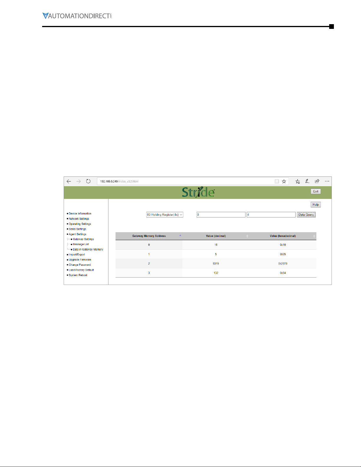
Data in Gateway Memory
The Data in Gateway Memory page is available under Agent Settings when the gateway is in Agent
mode. On the Data in Gateway Memory page, you may query the real-time data stored in the
gateway’s local cache as configured on the Message List page.
To query the Modbus data stored in gateway memory:
1) Enter the Modbus function code (shown in the previous table).
2) Enter the starting address to query within the selected region. The Starting Address refers to
the gateway internal address (0–65535) as shown in the previous table.
3) Enter the number of records to retrieve (data block size). Ensure that all addresses in that
block are configured in the table on the Message List page. Querying data outside of those
ranges will result in invalid values displaying on this page.
4) Click the “Data Query” button.
The results of the data query are displayed on the Data in Gateway Memory page, and
are automatically updated in realtime. This page may be useful for troubleshooting the
communications network.
Page 3-11Stride® MB Gateway User Manual – 1st Edition Rev. F – April 2021
Page 42

Chapter 3: Device Configuration
Import/Export
The gateway configuration settings may all be stored to or loaded from a text file as a convenience
when replacing the gateway or configuring multiple gateways with identical or similar settings.
Import/Export Screen
Export
Export the configuration file to a connected PC for backup or for configuring additional gateways.
The exported file can be edited by any text editor, such as Notepad++.
Import
An exported configuration file can be used to format a replacement gateway, to format additional
gateways, or the exported file can be modified and re-imported to the same gateway to revise
device settings. The filename must be [the part number].txt which is the same as an exported
configuration filename: SGW-MB1511-T.txt or SGW-MB1512-T.txt or SGW-MB1524-T.txt
Page 3-12 Stride® MB Gateway User Manual – 1st Edition Rev. F – April 2021
Page 43

Upgrade Firmware
Occasionally firmware revisions are released to make new features available or to fix bugs.
Upgrade Firmware Screen
Chapter 3: Device Configuration
To update the firmware, click Browse to locate and select the new firmware file on your PC, then
click Upgrade.
The gateway must be rebooted after firmware is upgraded in order for the new firmware to
take effect.
Page 3-13Stride® MB Gateway User Manual – 1st Edition Rev. F – April 2021
Page 44

Chapter 3: Device Configuration
Change Password
The STRIDE® gateways allow browser management access for the username “admin”. The default
password is admin. To provide an additional level of security, the password may be changed.
SECURITY NOTE: HTTPS may be selected to encrypt the traffic between the browser and the gateway.
When HTTPS is selected, the IP address in the browser address bar must be preceded by “https://”.
For example, “https://192.168.0.249”.
When a new password is entered here or HTTPS is selected, the browser will log you out of the
current session and return you to the login page to login using the new password.
NOTE: Make sure to record the new password. If the password is lost, the gateway must be reset
to factory defaults using the hardware reset button.
NOTE: Remember to click the SAVE button before you leave this page. Leaving the page before
saving changes will cancel changes.
Page 3-14 Stride® MB Gateway User Manual – 1st Edition Rev. F – April 2021
Page 45

Load Factory Default
In addition to the hardware Reset Defaults button on the top of the gateway, default settings
may be loaded from the browser interface. Upon clicking the “Load Factory Default” button, the
gateway will ask for confirmation of the changes then reboot in order for the change to defaults to
take effect.
Chapter 3: Device Configuration
NOTE: This will reset the IP address(es), the password and the HTTPS access. If the device IP
address had been previously changed, its default IP address after loading factory defaults may not
be accessible by your current PC settings.
Page 3-15Stride® MB Gateway User Manual – 1st Edition Rev. F – April 2021
Page 46

Chapter 3: Device Configuration
Reboot
The Reboot option will reboot the gateway. Rebooting here, or cycling power at the gateway itself,
is required after a firmware upgrade to make the new firmware take effect. All other configuration
changes are implemented without requiring a reboot.
Page 3-16 Stride® MB Gateway User Manual – 1st Edition Rev. F – April 2021
Page 47

AppEndix
AppEndix
AppEndix
ApplicAtion ExAmplEs
A
A
A
In T
hIs ChapTer
Example 1:
Using Modbus Poll to STRIDE Modbus Gateway with BRX Slave � � � � � � � � � � � � � � � � � A–2
Example 2:
Using Modbus Poll to STRIDE MB Gateway with CLICK Slave � � � � � � � � � � � � � � � � � � � A–9
Example 3:
Using P3000 as Master (Client) to STRIDE Modbus Gateway with CLICK Slave� � � � � � � � � � A–17
...
Page A–1Stride® MB Gateway User Manual – 1st Edition Rev. F – April 2021
Page 48
Appendix A: Application Examples
* Software-selectable
RS-485
Example 1: Using Modbus Poll to STRIDE Modbus Gateway with BRX Slave
This example will illustrate how to use Modbus Poll, which is a PC-based Modbus master simulator
tool, to connect through the STRIDE® Modbus Gateway to a BRX PLC via 2-wire RS-485. For
simplicity in this example, the gateway will be configured in Transparent Mode.
Items needed for this example:
• STRIDE
•
BRX PLC (any model)
•
PC with Modbus Poll installed (free demo is available at www�modbustools�com)
•
AutomationDirect ZL-DB9F-CBL-2P D-sub 9-pin pigtail cable, or small length of AutomationDirect
L-19954 RS-485 cable or equivalent and D-sub 9-pin socket (female) connector
•
Ethernet switch and cables to connect from the PC to
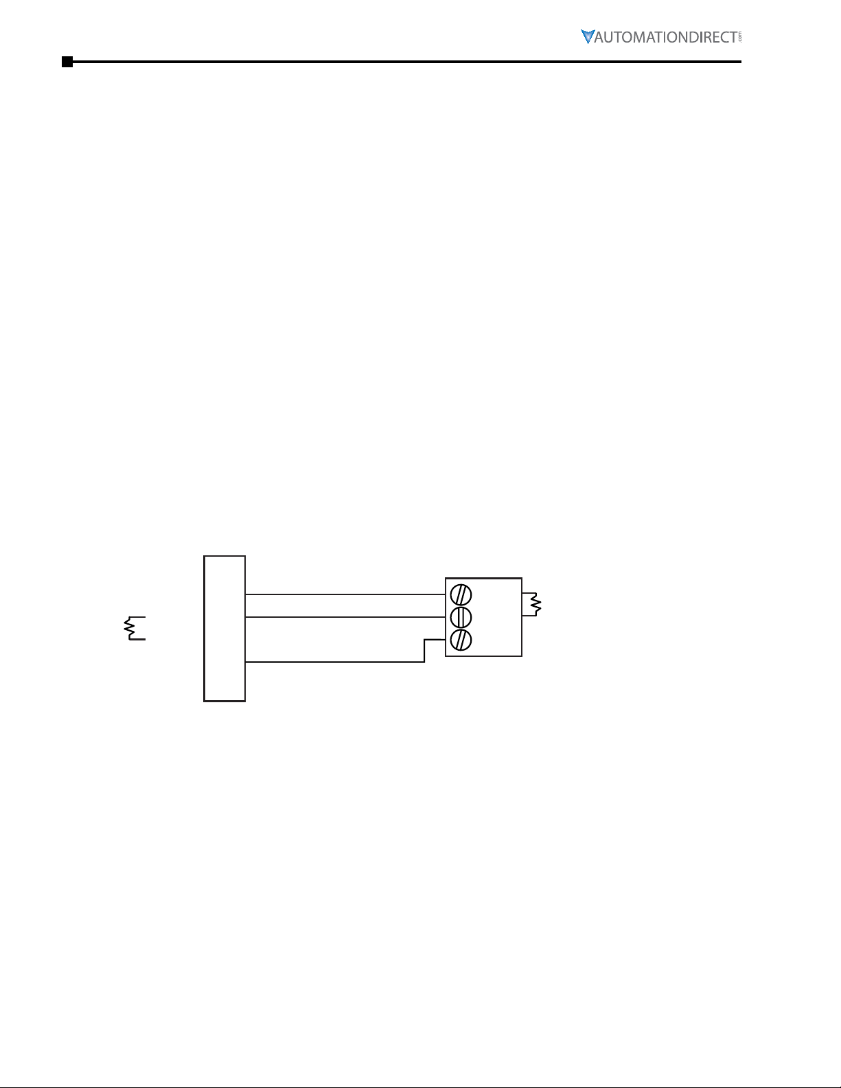
Step 1: Connect the STRIDE Modbus Gateway serial port to the BRX MPU serial port.
Using the ZL-DB9F-CBL-2P cable, or D-sub 9-pin connector and a short length of RS-485 cable,
connect Serial Port 1 of the STRIDE Modbus Gateway to the BRX serial port as shown:
Modbus Gateway
STRIDE
Modbus Gateway
RS-485 2-wire Wiring Diagram
Gateway
BRX MPU
RXDRXD+
TXDTXD+
GND
(NC)
The Gateway contains a DIP switch selectable 120Ω Termination
Resistor between TX+ and TX- for each serial port on RS485 2-wire,
when the Gateway is wired at one end of the serial network
1
2
3
4
5
6-9
D+
DGND
120Ω Termination
Resistor
*
Page A–2 Stride® MB Gateway User Manual – 1st Edition Rev. F – April 2021
Page 49
Appendix A: Application Examples
Step 2: Configure the BRX MPU serial port.
Connect to the BRX MPU with BRX Do-more! Designer software using either the BRX serial or USB
Pluggable Option Module.
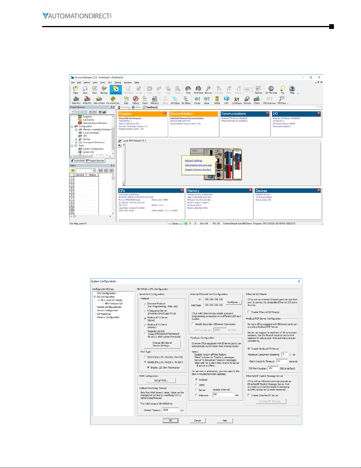
Click on the built-in serial port on the image of the BRX MPU within the Do-more! Designer
software. From the dialog box that pops up, select "Edit Protocol and Port Type"
Page A–3Stride® MB Gateway User Manual – 1st Edition Rev. F – April 2021
Page 50
Appendix A: Application Examples
In the Serial Port Configuration column, select "RS-485" under "Port Type" and select "Modbus
RTU server (slave)" under "Protocol". Then click "Change @IntSerial Device Settings..."
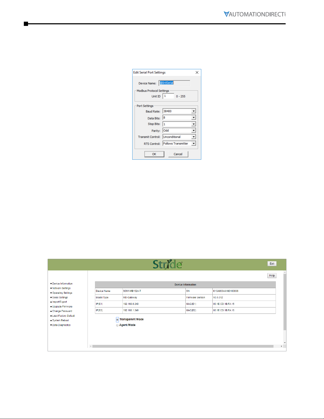
Setup the port as shown for 38400 baud rate, Odd parity, 1 Stop bit and Unit ID 1. Match everything
else as shown. Note the Unit ID configured in the PLC. Once this has been done, click "OK" to close
this dialog then "OK" again to close the preceding dialog.
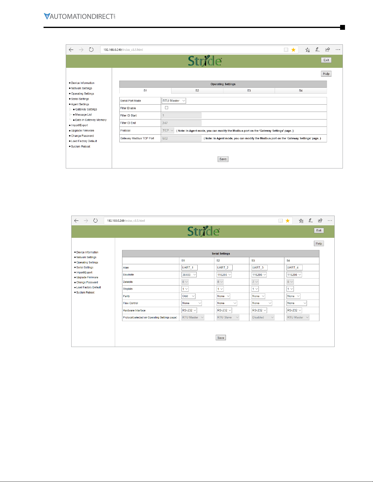
Step 3: Configure the STRIDE Modbus Gateway
Open up a web browser, such as Internet Explorer, enter in the IP address of the STRIDE Modbus
Gateway, and log into the STRIDE Modbus Gateway web console as described in the Initial
Connection section of Chapter 3 to access the Device Information as shown:
Set the gateway to Transparent Mode.
Page A–4 Stride® MB Gateway User Manual – 1st Edition Rev. F – April 2021
Page 51
Appendix A: Application Examples
On the Operating Settings page, set Serial Port 1 to RTU Master mode as shown below and click Save.
Click "Serial Settings" from the navigation menu
Set the serial port parameters to match the configuration of the BRX MPU, and set the hardware
interface to RS-485 2-wire.
Click "Save" to store and apply the settings.
Page A–5Stride® MB Gateway User Manual – 1st Edition Rev. F – April 2021
Page 52
Appendix A: Application Examples
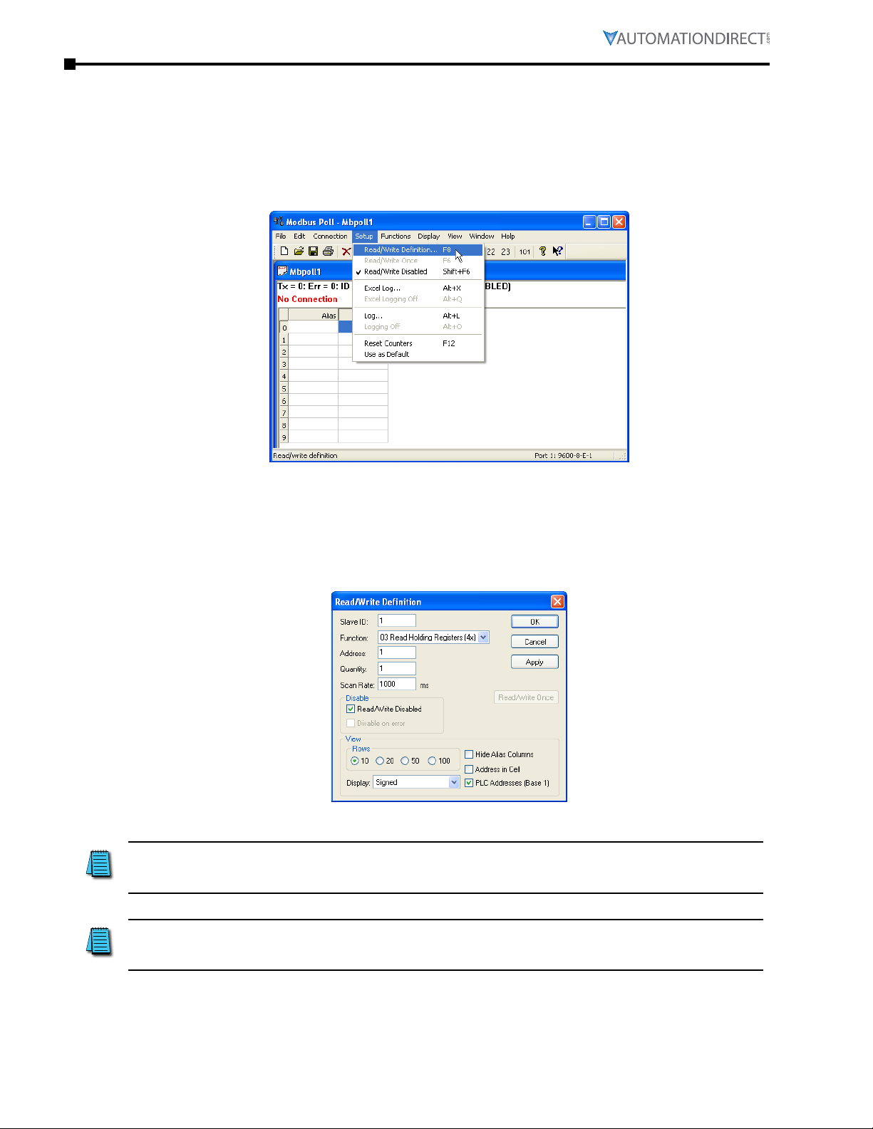
Step 4: Connect to the STRIDE Modbus Gateway using the Modbus Poll simulator software.
Once the software has been obtained from www.modbustools.com and installed according to the
directions provided from their website, open up the Modbus Poll software.
Click on the Setup pulldown menu and select Read/Write Definition as shown:
Configure the Read/Write definition for a simple read of the register 400001, which equates to
MHR1 (16 bit word, decimal data type) in the BRX MPUs.
Enter 1 for the Slave ID. This matches the Unit ID in the protocol that will determine which Modbus
Serial slave will be targeted on the serial side of the Stride Modbus Gateway. Entering 1 here will
match up to the Station Number configured above in Do-more! Designer for the BRX MPU.
Choosing Function 3 sets up the read for 4xxxxx registers. Checking the “PLC Addresses (Base 1)”
in the lower right corner matches the addressing to the cross reference chart mentioned above.
Once this windows has been configured as shown above, click on OK.
Page A–6 Stride® MB Gateway User Manual – 1st Edition Rev. F – April 2021
Page 53
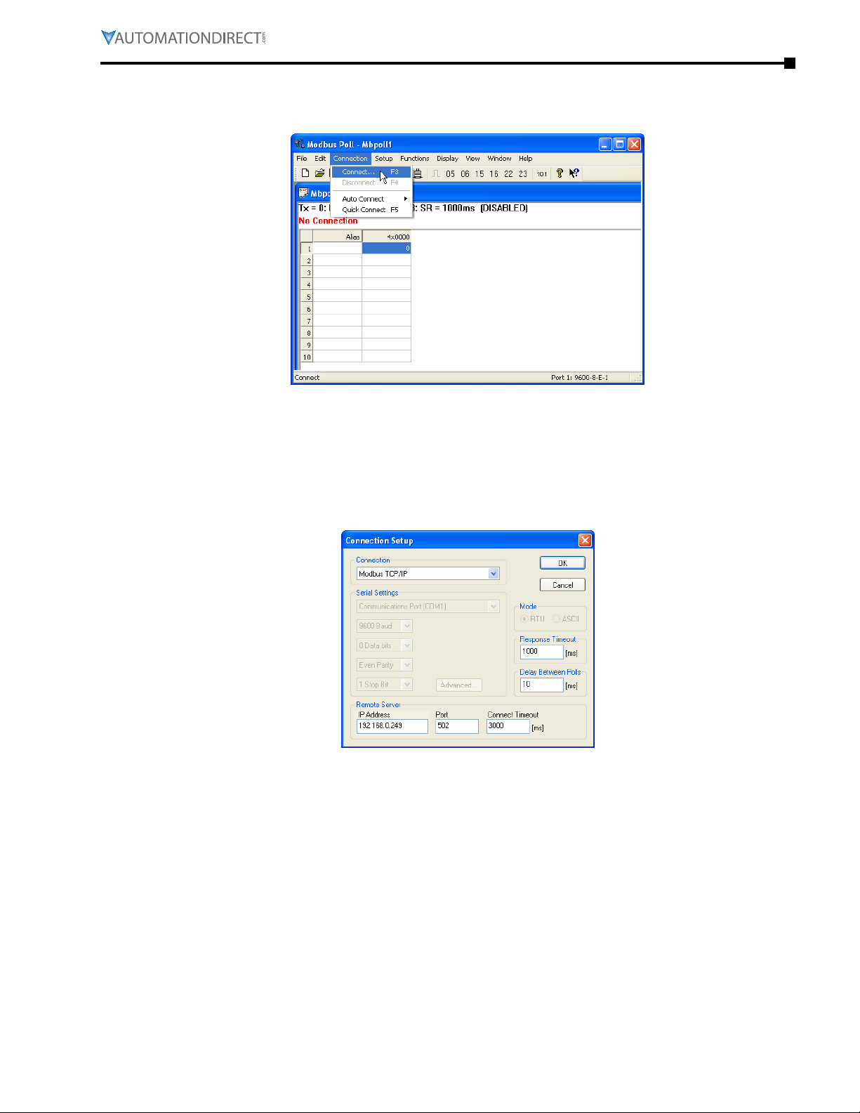
Appendix A: Application Examples
Now click on the Connection pulldown menu and select Connect:
In the Connection Setup window, choose the Modbus TCP/IP connection type. Enter the IP address
of your STRIDE Modbus Gateway module in the lower left hand corner. Match everything else as
shown:
Click on OK to connect to the STRIDE Modbus Gateway.
If everything has been configured correctly, the counter next to “TX =” will increment rapidly and
the counter next to “Err =” will not increment. If the Error counter is incrementing, go back and
verify that all the steps prior to this one have been followed. If you get an error that says, “Modbus
TCP connection failed”, verify that the IP address of the PC and the IP address of the STRIDE
Modbus Gateway are in compatible subnets and can communicate.
Page A–7Stride® MB Gateway User Manual – 1st Edition Rev. F – April 2021
Page 54
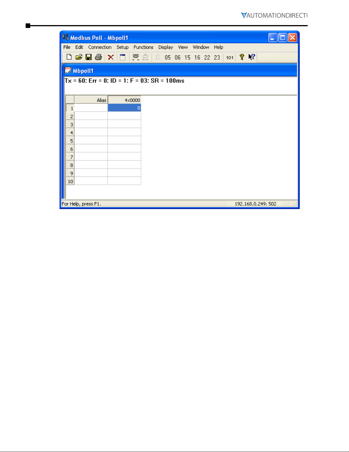
Appendix A: Application Examples
Once Modbus Poll is communicating to the PLC, go into Do-more! Designer, open a Data View
window and enter MHR1. Change the display type to “Decimal” to match the Modbus Poll
Change the value in data view for MHR1 to various values and watch the value change in Modbus
Poll to match.
Page A–8 Stride® MB Gateway User Manual – 1st Edition Rev. F – April 2021
Page 55
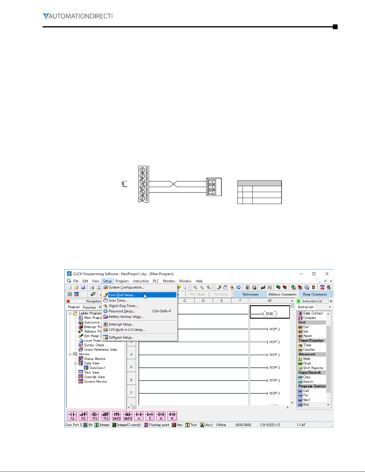
Appendix A: Application Examples
RS-485
Example 2: Using Modbus Poll to STRIDE MB Gateway with CLICK Slave
This example will illustrate how to use Modbus Poll, which is a PC based Modbus master simulator
tool, to connect through the STRIDE Modbus Gateway to a CLICK PLC via 2 wire RS-485.
Items needed for this example:
• STRIDE
•
CLICK PLC (any C0-01xx-x or C0-02xx-x PLC with 3 pin terminal RS-485 port)
•
PC with Modbus Poll installed (free demo is available at www�modbustools�com)
•
Small length of AutomationDirect L-19954 RS-485 cable or equivalent
•
Ethernet switch and cables to connect from the PC to
Step 1: Connect the STRIDE Modbus Gateway serial port to Port 3 of the CLICK PLC.
Using the short length of RS-485 cable, connect the STRIDE Modbus Gateway to CLICK’s Port 3 as shown:
Modbus Gateway
STRIDE
Modbus Gateway
Gateway
RX-
RX+
TXTX+
GND
6-9 NC
(The Gateway contains a DIP switch selectable
120Ω Termination Resistor between TX+ and TXfor each serial port on a RS485 2-wire network.)
Port 3
3 Pin
Terminal Block
+
LG
Port 3 Pin Descriptions
1
2
3
+
(plus)
-
(minus)
LG
Signal A (RS-485)
Signal B (RS-485)
Logic Ground (0V)
-
Step 2: Configure the CLICK serial port.
Connect to the CLICK PLC with CLICK programming software. Go to the Setup pulldown and select
Com Port Setup... as shown:
Page A–9Stride® MB Gateway User Manual – 1st Edition Rev. F – April 2021
Page 56
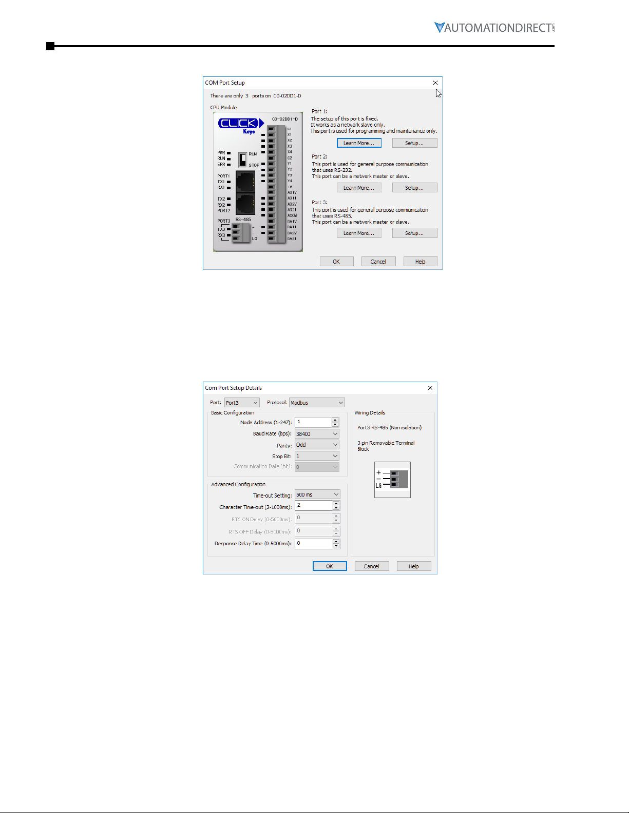
Appendix A: Application Examples
Click the Port 3: Setup... button to configure Port 3 of the PLC.
Configure the port for 38400 baud rate, Odd parity, 1 Stop Bit and Node Address 1. Leave the other
settings as shown below. Note the Node Address number configured here. Once the settings are
configured, Click on the Ok button.
Page A–10 Stride® MB Gateway User Manual – 1st Edition Rev. F – April 2021
Page 57
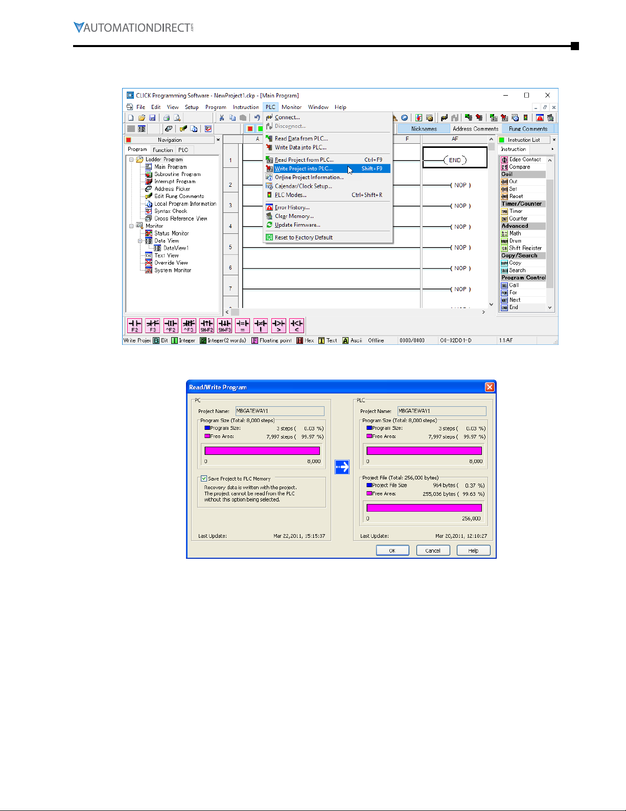
Appendix A: Application Examples
Next, transfer the project to the PLC for the Port 3 settings to take effect. Select the PLC pulldown
menu and choose Write Project into PLC...
Choose Ok and follow the steps when prompted to transfer the project to the PLC.
Page A–11Stride® MB Gateway User Manual – 1st Edition Rev. F – April 2021
Page 58

Appendix A: Application Examples
Step 3: Configure the STRIDE Modbus Gateway
Open up a web browser, such as Internet Explorer, enter in the IP address of the STRIDE Modbus
Gateway, and log into the STRIDE Modbus Gateway web console as described in the Initial
Connection section of Chapter 2 to access the Device Information as shown:
Set the gateway to Transparent Mode.
On the Operating Settings page, set Serial Port 1 to RTU Master mode as shown below and click
Save.
Page A–12 Stride® MB Gateway User Manual – 1st Edition Rev. F – April 2021
Page 59

Appendix A: Application Examples
Click "Serial Settings" from the navigation menu
Set the serial port parameters to match the configuration of the CLICK PLC, and set the hardware
interface to RS-485 2-wire.
Click "Save" to store and apply the settings.
Step 4: Connect to the STRIDE Modbus Gateway using the Modbus Poll simulator software.
Once the software has been obtained from www.modbustools.com and installed according to the
directions provided from their website, open up the Modbus Poll software.
Click on the Setup pulldown menu and select Read/Write Definition as shown:
Page A–13Stride® MB Gateway User Manual – 1st Edition Rev. F – April 2021
Page 60

Appendix A: Application Examples
Configure the Read/Write definition for a simple read of the register 400001, which equates to DS1
in the CLICK PLC as shown.
Enter 1 for the Slave ID. This matches the Unit ID in the protocol that will determine which
Modbus Serial slave will be targeted on the serial side of the Stride Modbus Gateway. Entering 1
here will match up to the Station Number configured above in the CLICK software.
Page A–14 Stride® MB Gateway User Manual – 1st Edition Rev. F – April 2021
Page 61

Appendix A: Application Examples
Choosing Function 3 sets up the read for 4xxxxx registers. Checking the “PLC Addresses (Base 1)”
in the lower right corner matches the addressing to the cross reference chart mentioned above.
Once this window has been configured as shown above, click on OK.
Now click on the Connection pulldown menu and select Connect:
In the Connection Setup window, choose the Modbus TCP/IP connection type. Enter the IP address of
your STRIDE Modbus Gateway module in the lower left hand corner. Match everything else as shown:
Click on OK to connect to the STRIDE MB Gateway.
If everything has been configured correctly, the counter next to “TX =” will increment rapidly and
the counter next to “Err =” will not increment. If the Error counter is incrementing, go back and
verify that all the steps prior to this one have been followed. If you get an error that says, “Modbus
TCP connection failed”, verify that the IP address of the PC and the IP address of the STRIDE
Modbus Gateway are in compatible subnets and can communicate.
Page A–15Stride® MB Gateway User Manual – 1st Edition Rev. F – April 2021
Page 62

Appendix A: Application Examples
Once Modbus Poll is communicating to the PLC, go into the CLICK programming software, open up
a Data View window and enter in DS1 as shown.
Change the value in data view for DS1 to various values and watch the value change in Modbus
Poll to match.
Page A–16 Stride® MB Gateway User Manual – 1st Edition Rev. F – April 2021
Page 63

Appendix A: Application Examples
Example 3: Using P3000 as Master (Client) to STRIDE Modbus Gateway with CLICK Slave.
Step 1: Connect CLICK to the STRIDE Modbus Gateway as shown in example 2.
Step 2: Connect P3000 CPU (P3-550) to STRIDE Modbus Gateway via Ethernet Switch and Two
Ethernet Cables.
Configure the IP address of the P3000 or P3-550 CPU and the STRIDE Modbus Gateway to be
compatible subnets. Steps to configure the IP address of the P3-550 CPU areas follows:
Click on Setup on the top menu bar and choose “Hardware Configuration”.
Double click on the image of the P3-550 in the center of the hardware configuration.
Page A–17Stride® MB Gateway User Manual – 1st Edition Rev. F – April 2021
Page 64
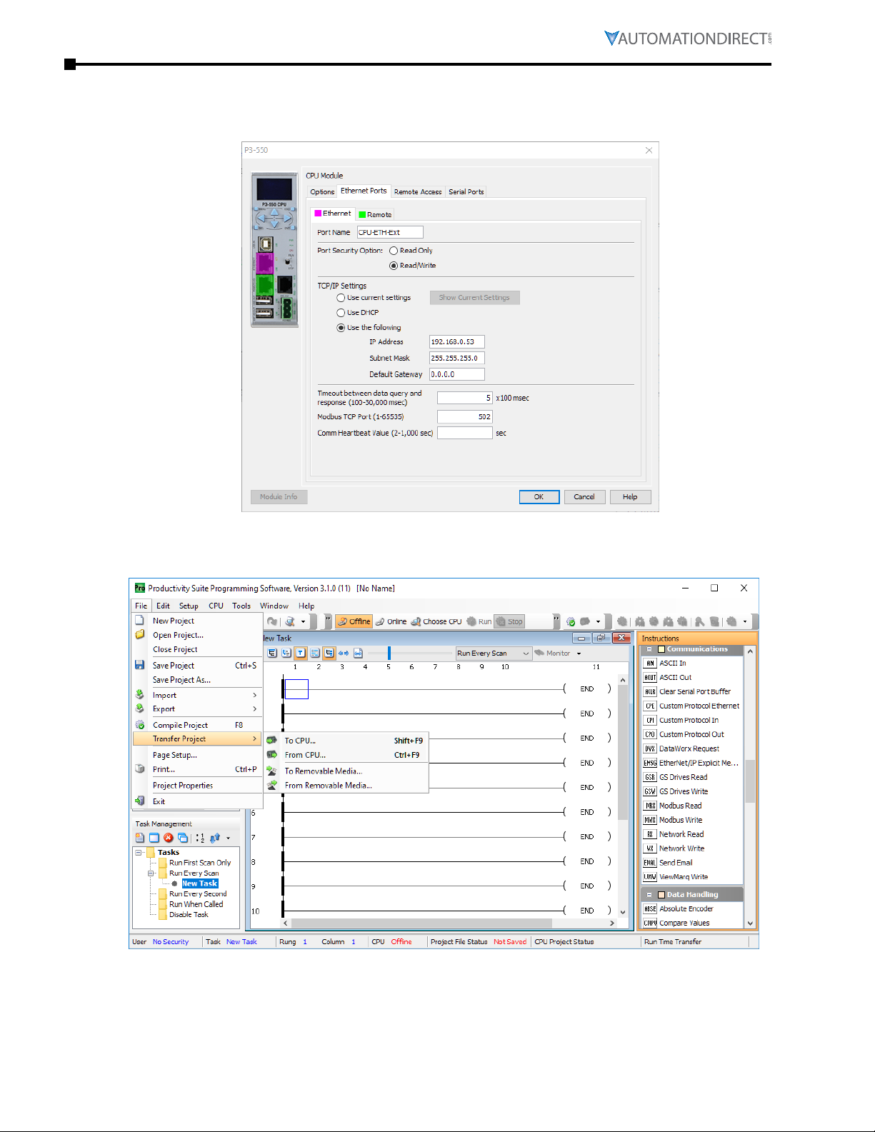
Appendix A: Application Examples
Click on the “Ethernet Ports” tab and configure the IP address in the “Use the Following:” IP
address field. Once the correct IP address and Subnet Mask is entered, click on the OK button and
close the hardware configuration window.
Transfer the project to the PLC in order to have the new settings take effect. To do this, select File
from the pulldown menu and then Transfer Project >To PLC…
Step 3: Configure the MRX instruction to read data from the STRIDE Modbus Gateway.
Double click on the instruction MRX Read to configure the MRX instruction as shown.
Page A–18 Stride® MB Gateway User Manual – 1st Edition Rev. F – April 2021
Page 65
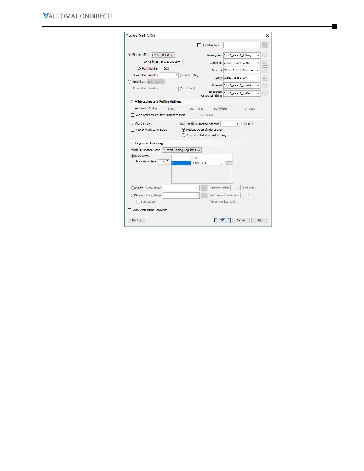
Appendix A: Application Examples
IP Address: address of the STRIDE Modbus Gateway.
TCP Port Number: Leave at default 502.
Slave Node Number: This should match the Node address of Port 3 of the CLICK PLC. Leave at 1
in this case.
Slave Modbus Starting Address: Set to 1 to read address DS1 in the CLICK PLC.
Tag Name Mapping: Create a Tag called CLICK_DS1 as an Signed Int 16 Tag to read in DS1 from
the CLICK PLC.
Use the status bits and Exception Response String to verify whether communications were
successful or not. If the Error bit comes on, look at the Exception Response String to see which
error occurred. If the Timeout Bit comes on, check the IP address settings of the P3-550 and the
STRIDE Modbus Gateway and make sure that they are in compatible subnets.
If the Successful Status bit comes on, add the CLICK_DS1 tag to the Data View at the bottom of the
Productivity Suite Programming Software and check the values. Change the values in the CLICK
data view for DS1 and verify that the CLICK_DS1 tag matches.
Page A–19Stride® MB Gateway User Manual – 1st Edition Rev. F – April 2021
Page 66

Appendix A: Application Examples
Page A–20 Stride® MB Gateway User Manual – 1st Edition Rev. F – April 2021
Page 67

appendix
appendix
appendix
Stride ModbuS Gateway operatinG
Mode exaMpleS
B
B
B
In T
hIs ChapTer
Example 1:
TRANSPARENT Mode, with Modbus TCP Master (Client) Devices to
Modbus RTU/ASCII Slave Devices � � � � � � � � � � � � � � � � � � � � � � � � � � � � � � � � � � �B–2
Example 2:
TRANSPARENT Mode, with Modbus RTU/ASCII Master Devices to
Modbus TCP Slave (Server) Devices � � � � � � � � � � � � � � � � � � � � � � � � � � � � � � � � � �B–6
Example 3:
AGENT Mode, with Modbus TCP Master (Client) Devices to
Modbus RTU/ASCII Slave Devices � � � � � � � � � � � � � � � � � � � � � � � � � � � � � � � � � � B–11
Example 4:
AGENT Mode, with Modbus RTU/ASCII Master Devices to
Modbus TCP Slave (Server) Devices � � � � � � � � � � � � � � � � � � � � � � � � � � � � � � � � � B–16
...
Page B–1Stride® MB Gateway User Manual – 1st Edition Rev. F – April 2021
Page 68
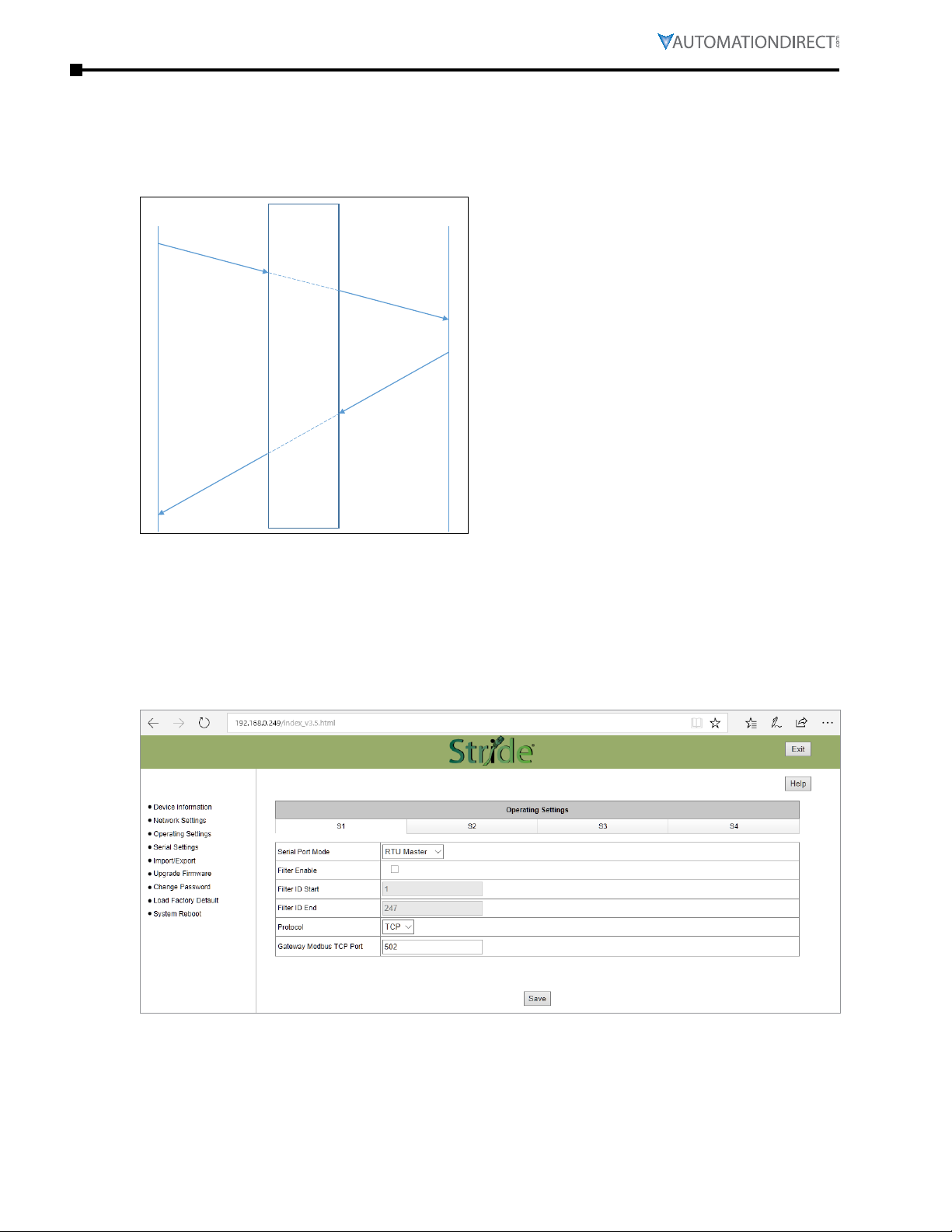
Appendix B: Stride® Modbus Gateway Operating Mode Examples
Client
Slave
Example 1: TRANSPARENT Mode, with Modbus TCP Master (Client) Devices to Modbus RTU/ASCII Slave Devices
TCP
Modbus query
Modbus response
Gateway
Server
RTU or ASCII
Modbus query
Master
Modbus response
Provide power to the STRIDE Modbus Gateway, connect to an Ethernet port and log on to the
gateway configuration interface.
Our example assumes default values in the gateway. Click Load Factory Default.
Set the operation mode to Transparent Mode.
Browse to “Operating Settings” to select S1 and set its parameters, as shown in Figure 1.
Figure 1. STRIDE Modbus Operating Settings.
Click Save.
Page B–2 Stride® MB Gateway User Manual – 1st Edition Rev. F – April 2021
Page 69
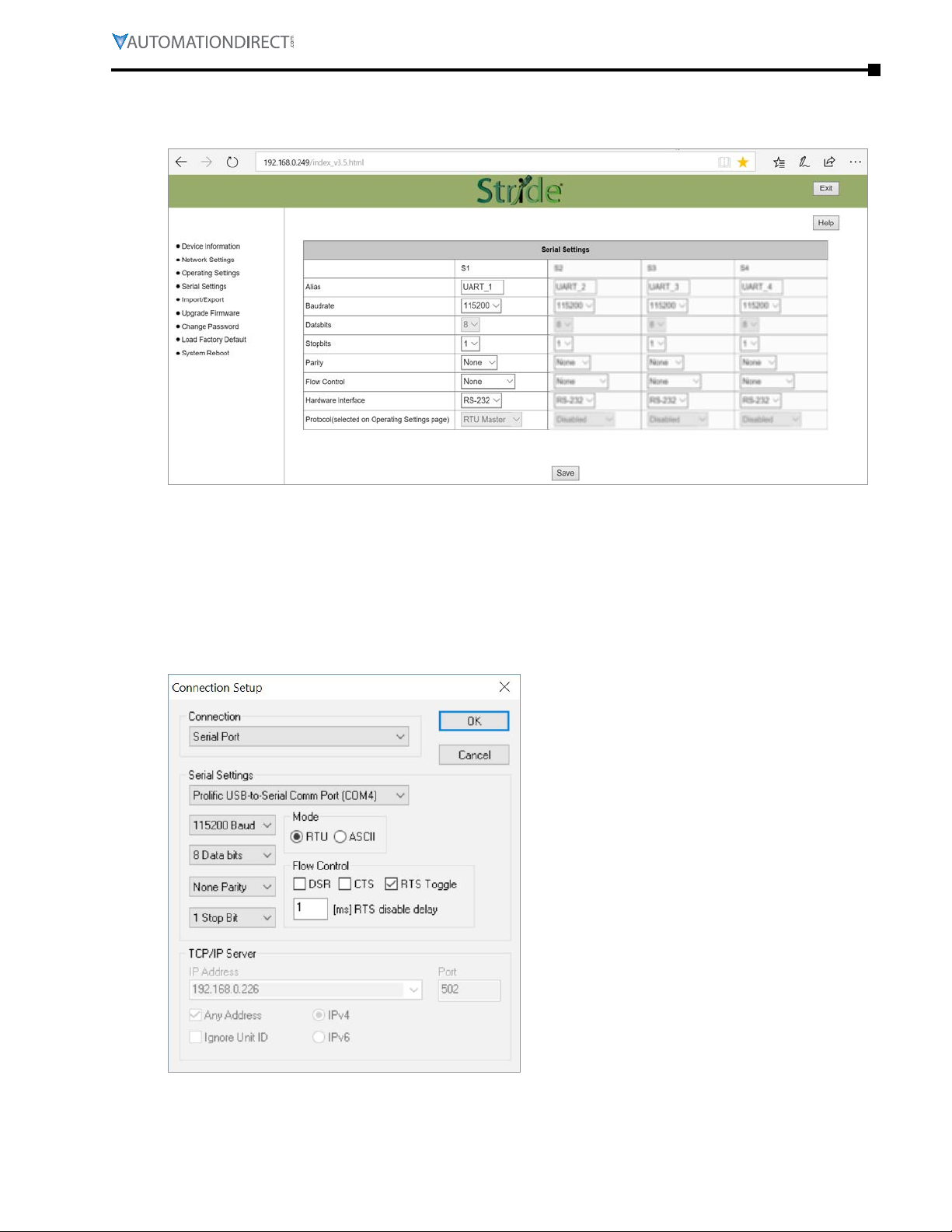
Appendix B: Stride® Modbus Gateway Operating Mode Examples
Then browse to “Serial Settings” to configure serial port S1 as shown in Figure 2.
Click the Save button to save and apply the changes.
Figure 2. STRIDE Modbus Serial Settings.
Connect the STRIDE Modbus Gateway serial port S1 to your PC’s serial port (possibly requiring a
USB to serial converter), and run Modbus Slave software on the PC. The Modbus Slave parameters
must be configured as shown in Figure 3.
Figure 3. Modbus Slave Configuration.
Page B–3Stride® MB Gateway User Manual – 1st Edition Rev. F – April 2021
Page 70
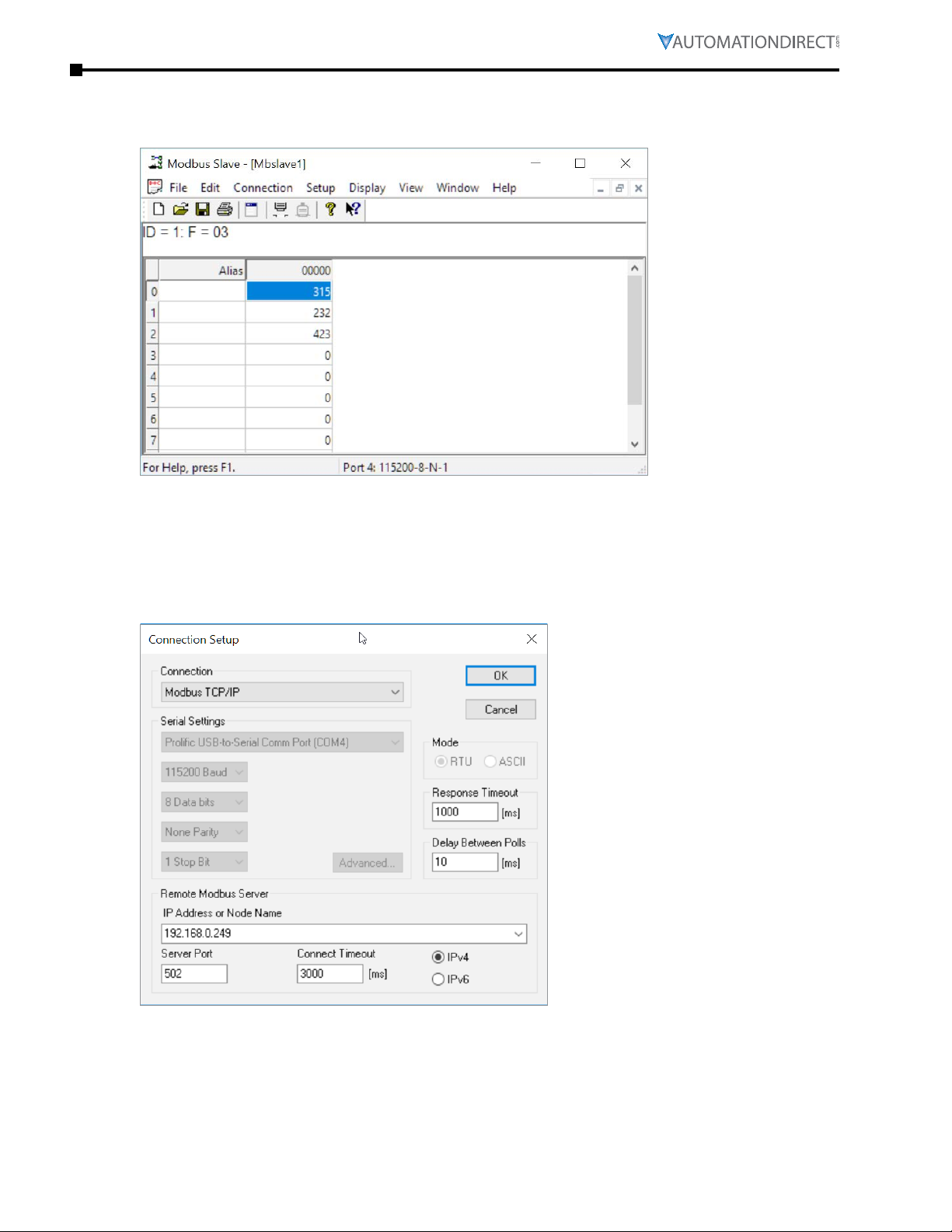
Appendix B: Stride® Modbus Gateway Operating Mode Examples
Click OK button (shown in Figure 3) to return to the data window shown in Figure 4.
Figure 4. Modbus Slave.
Open Modbus Poll on your PC and set the parameters as shown in Figure 5.
Figure 5. Modbus Poll Configuration.
Page B–4 Stride® MB Gateway User Manual – 1st Edition Rev. F – April 2021
Page 71
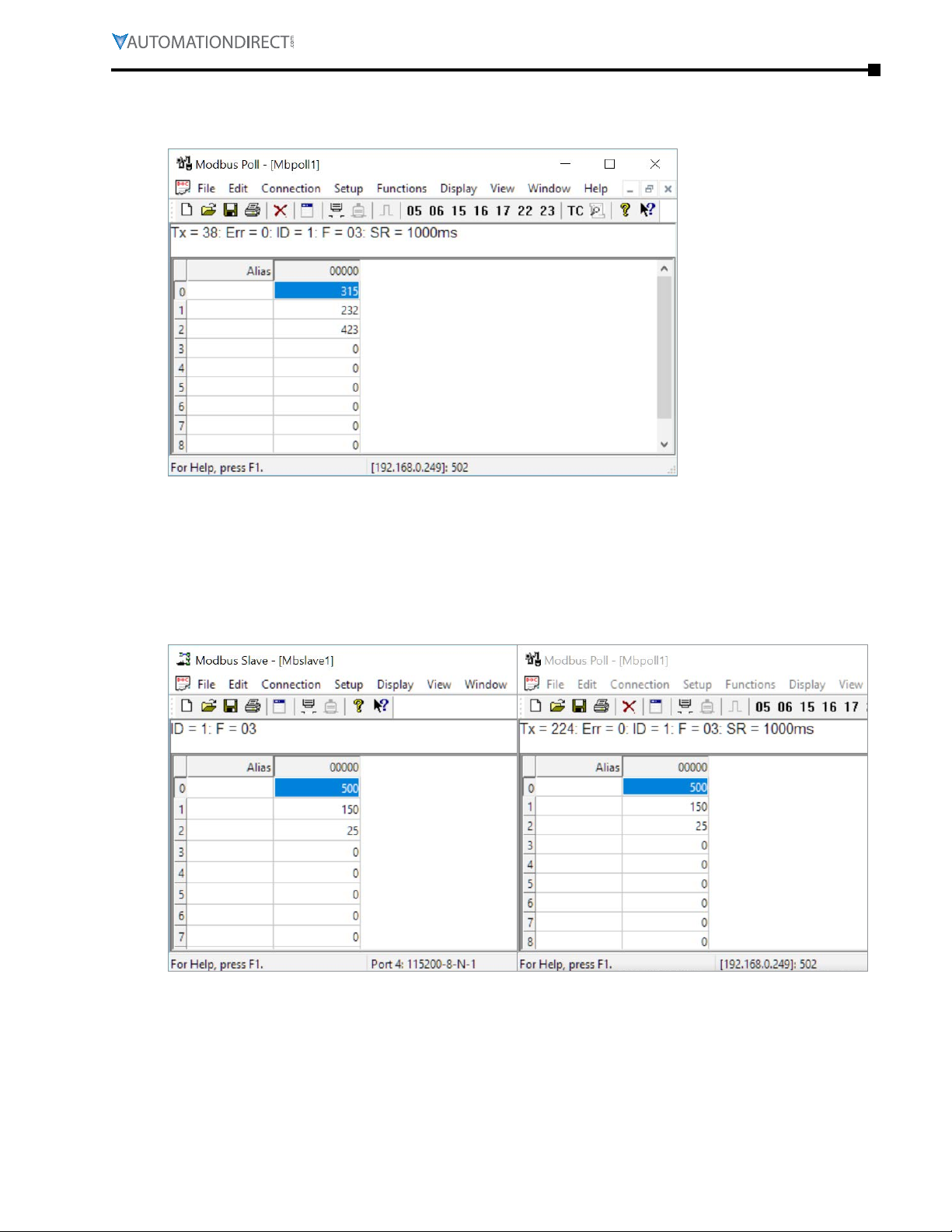
Appendix B: Stride® Modbus Gateway Operating Mode Examples
Click OK button (shown in Figure 5) to return to the data window shown in Figure 6.
Figure 6. Modbus Poll.
Now let’s experiment with our master reading data from our slave. Enter data in address 1 and
address 2 in Modbus Slave and watch as Modbus Poll reads that data, as shown in Figure 7.
Figure 7. Data Test Result.
Page B–5Stride® MB Gateway User Manual – 1st Edition Rev. F – April 2021
Page 72
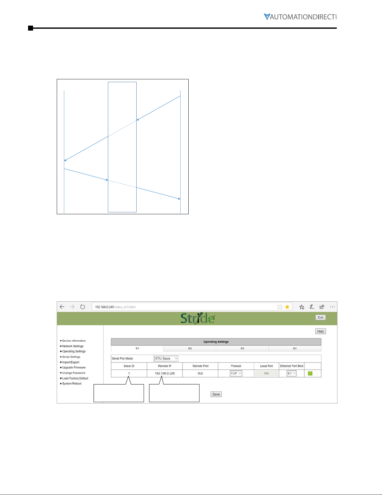
Appendix B: Stride® Modbus Gateway Operating Mode Examples
Server
Example 2: TRANSPARENT Mode, with Modbus RTU/ASCII Master Devices to Modbus TCP Slave (Server) Devices
TCP
Gateway
RTU or ASCII
Modbus query
Master
Modbus query
Client
Modbus response
Slave
Modbus response
Provide power to the STRIDE Modbus Gateway, connect to an Ethernet port and log on to the
gateway configuration interface.
Our example assumes default values in the gateway. Click Load Factory Default.
Set the operation mode to Transparent Mode. Browse to “Operating Settings” to configure serial
port S1 as shown in Figure 9. Note that the Remote IP Address is your PC’s IP address, since the PC
(Modbus Slave) is the slave device for this example.
Click Save.
Remember this
Slave ID number
This is your PC
IPaddress
Figure 9. STRIDE Modbus Gateway Serial Settings.
Browse to STRIDE Modbus “Serial Settings” to select S1 and set its parameters, as shown in Figure
10. Click Save to save and apply the changes.
Page B–6 Stride® MB Gateway User Manual – 1st Edition Rev. F – April 2021
Page 73
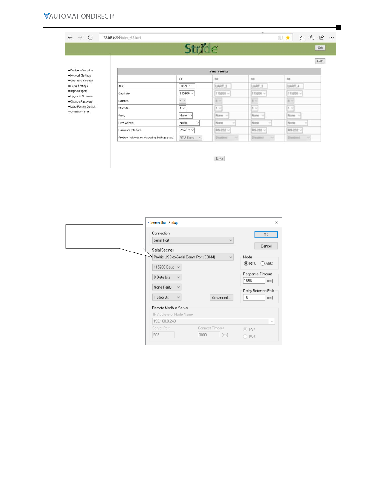
Appendix B: Stride® Modbus Gateway Operating Mode Examples
Figure 10. STRIDE Modbus Gateway Serial Settings.
Connect the STRIDE Modbus Gateway serial port S1 to your PC’s serial port (possibly requiring a
USB to serial converter), and run Modbus Poll software on the PC. The Modbus Poll parameters
must be configured as shown in Figure 11.
This value is the COM port
assigned by your PC. It can be
found in the Device Manager.
Figure 11. Modbus Poll Configuration.
Click OK in Figure 11 to return to the Modbus Poll main window.
Page B–7Stride® MB Gateway User Manual – 1st Edition Rev. F – April 2021
Page 74

Appendix B: Stride® Modbus Gateway Operating Mode Examples
Select Setup - Read/Write Definition.
Figure 12. Modbus Poll Read/Write Definition.
Enter the Slave ID of the Gateway as shown in Figure 12. This is the Slave ID you assigned to the
Gateway in its “Operating Settings” configuration.
Click OK shown in Figure 12 to return to the application interface shown in Figure 13.
Figure 13. Modbus Poll Initial Connection.
The Modbus Poll software will indicate a Timeout Error until the Modbus Slave software is
connected in the next step.
Page B–8 Stride® MB Gateway User Manual – 1st Edition Rev. F – April 2021
Page 75

Appendix B: Stride® Modbus Gateway Operating Mode Examples
Run the Modbus Slave software on your PC and set the parameters shown in Figure 14.
Figure 14. Modbus Slave Configuration.
Click OK shown in Figure 14 to return to the Modbus Slave main window.
Select Setup - Slave Definition.
Figure 15. Modbus Poll Read/Write Definition.
Enter the Slave ID as shown in Figure 15. This is the Slave ID you assigned to the Modbus TCP
Client in the “Operating Settings” configuration.
Page B–9Stride® MB Gateway User Manual – 1st Edition Rev. F – April 2021
Page 76

Appendix B: Stride® Modbus Gateway Operating Mode Examples
Click OK shown in Figure 15 to return to the application interface shown in Figure 16.
Figure 16. Modbus Slave.
Now let’s experiment with our master reading data from our slave. Enter data in address 2 and
address 3 in Modbus Slave and watch as Modbus Poll reads that data, as shown in Figure 17.
Figure 17. Data Test Result.
Page B–10 Stride® MB Gateway User Manual – 1st Edition Rev. F – April 2021
Page 77

Appendix B: Stride® Modbus Gateway Operating Mode Examples
Client
Slave
Example 3: AGENT Mode, with Modbus TCP Master (Client) Devices to Modbus RTU/ASCII Slave Devices
TCP
Modbus query
Gateway responds
with cached data
Gateway
Cached
Server
data
RTU or ASCII
Modbus query
Modbus response
Modbus query
Modbus response
Modbus query
Master
Modbus response
Provide power to the STRIDE Modbus Gateway, connect to an Ethernet port and log on to the
gateway configuration interface.
Our example assumes default values in the gateway. Click Load Factory Default.
Set the operation mode to Agent Mode. Browse to “Operating Settings” to configure serial port S1
as shown in Figure 18. Click Save.
Figure 18. STRIDE Modbus Operating Settings.
Page B–11Stride® MB Gateway User Manual – 1st Edition Rev. F – April 2021
Page 78

Appendix B: Stride® Modbus Gateway Operating Mode Examples
Browse to “Serial Settings” to select S1 and set its parameters, as shown in Figure 19.
Click Save to save the changes.
Figure 19. Serial Settings Configuration.
Browse to “Gateway Settings” and configure the parameters as shown in Figure 20.
Click Save to save and apply the changes.
Figure 20. STRIDE Modbus Gateway Operating Settings.
Page B–12 Stride® MB Gateway User Manual – 1st Edition Rev. F – April 2021
Page 79

Appendix B: Stride® Modbus Gateway Operating Mode Examples
Browse to Message List-Add Message to add a message, shown in Figure 21.
Figure 21. Add Message.
Connect the STRIDE Modbus Gateway’s serial port S1 to PC’s serial port (possibly requiring a USB
to serial converter), and run the Modbus Slave software on PC. The Modbus Slave parameters
must be configured as shown in Figure 22.
This value is the COM port
assigned by your PC. It can be
found in the Device Manager.
Figure 22. Modbus Slave Configuration.
Page B–13Stride® MB Gateway User Manual – 1st Edition Rev. F – April 2021
Page 80

Appendix B: Stride® Modbus Gateway Operating Mode Examples
Click OK as shown in Figure 22 to return to the application interface shown in Figure 23.
Figure 23. Modbus Slave.
Open Modbus Poll on your PC and set the parameters as shown in Figure 24.
Figure 24. Modbus Poll Configuration.
Click the OK button shown in Figure 24.
Page B–14 Stride® MB Gateway User Manual – 1st Edition Rev. F – April 2021
Page 81
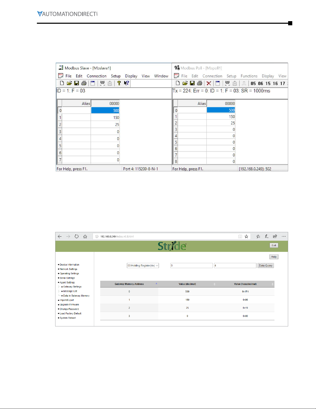
Appendix B: Stride® Modbus Gateway Operating Mode Examples
Now let’s experiment with watching data as it is read from Modbus Slave by the gateway then read
from the Gateway by Modbus Poll. Enter data in address 1 and address 2 in Modbus Slave and
watch the values change in Modbus Poll, as shown in Figure 25.
Figure 25. Data Test Result.
Now let’s take a look at the data as it’s stored in the gateway.
In the gateway User Interface, browse to the Data in Gateway Memory page.
Enter the Mapping Address (found on the “Message List” page) and the quantity of values you’d
like to view. For our example, these values are 0 and 4, respectively.
Figure 26. STRIDE Modbus Data in Gateway Memory.
Make changes in the Modbus slave user interface and watch the values change in the gateway’s
memory.
Page B–15Stride® MB Gateway User Manual – 1st Edition Rev. F – April 2021
Page 82
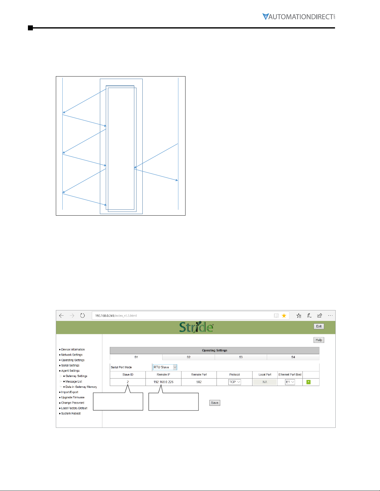
Appendix B: Stride® Modbus Gateway Operating Mode Examples
Server
Master
Example 4: AGENT Mode, with Modbus RTU/ASCII Master Devices to Modbus TCP Slave (Server) Devices
TCP
Modbus query
Modbus response
Modbus query
Modbus response
Modbus query
Modbus response
Gateway
Cached
Client
RTU or ASCII
data
Modbus query
Gateway responds
with cached data
Slave
Provide power to the STRIDE Modbus Gateway, connect to an Ethernet port and log on to the
gateway configuration interface.
Our example assumes default values in the gateway. Click Load Factory Default.
Set the operation mode to Agent Mode. Browse to “Operating Settings” and select S1. Setup
parameters for one Modbus TCP server as shown in Figure 27. Note that the Remote IP Address is
your PC’s IP address, since the PC (Modbus Slave) is the slave device for this example. Remember
the Slave ID you assign here.
Click Save.
Remember this
Slave ID number
This is your PC
IPaddress
Figure 27. STRIDE Modbus Operating Settings.
Page B–16 Stride® MB Gateway User Manual – 1st Edition Rev. F – April 2021
Page 83
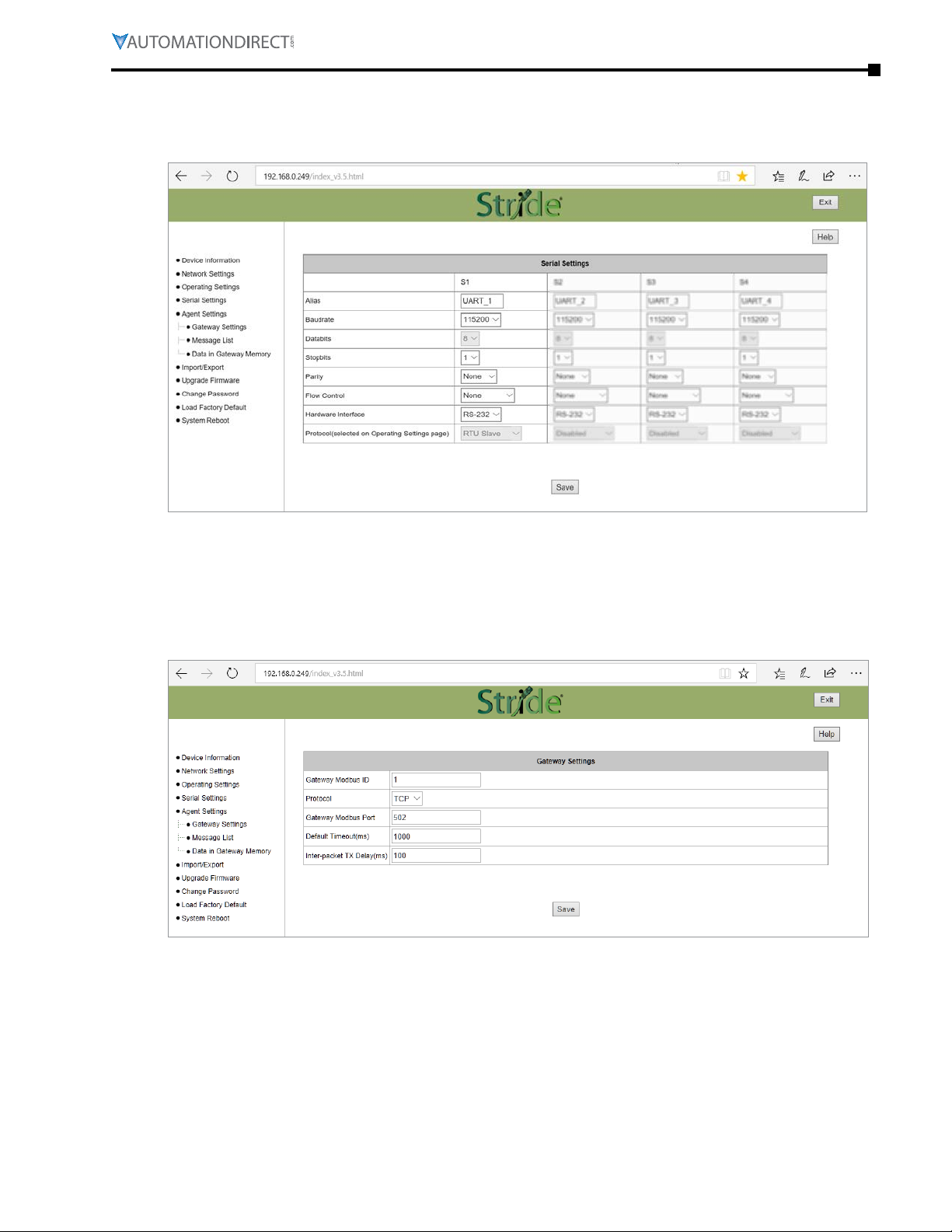
Appendix B: Stride® Modbus Gateway Operating Mode Examples
Browse to “Serial Settings” to configure the gateway shown in Figure 28.
Click Save to save the changes.
Figure 28. Serial Settings Configuration.
Browse to the “Gateway Settings” page to configure the gateway as shown in Figure 29. Click Save
to save and apply the changes.
Figure 29. Gateway Settings Configuration.
Page B–17Stride® MB Gateway User Manual – 1st Edition Rev. F – April 2021
Page 84
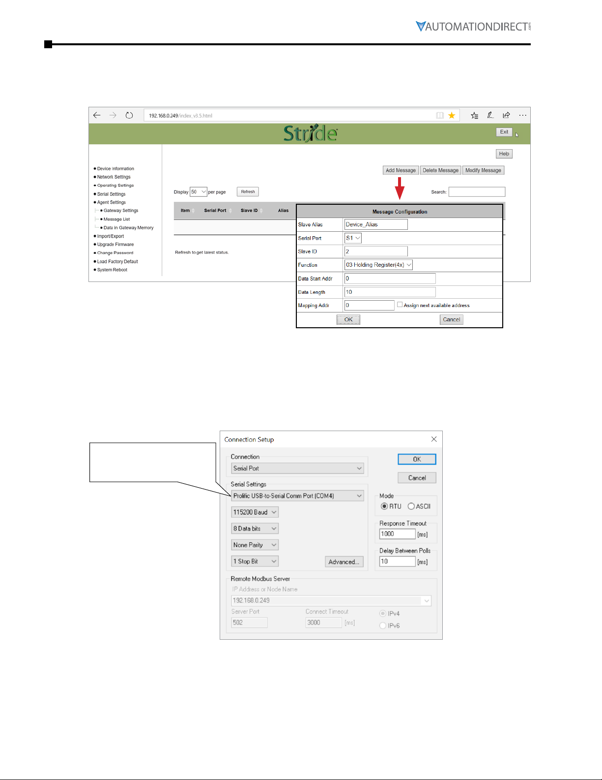
Appendix B: Stride® Modbus Gateway Operating Mode Examples
Browse to Message List-Add Message to add a message, shown in Figure 30. The Slave ID is the ID
you assigned to the slave device in the Operating Settings configuration in Figure 27.
Figure 30. Add Message.
Connect the STRIDE Modbus Gateway serial port S1 to your PC’s serial port (possibly requiring a
USB to serial converter), and run Modbus Poll software on the PC. The Modbus Poll parameters
must be configured as shown in Figure 31.
This value is the COM port
assigned by your PC. It can be
found in the Device Manager.
Figure 31. Modbus Poll Configuration.
Page B–18 Stride® MB Gateway User Manual – 1st Edition Rev. F – April 2021
Page 85
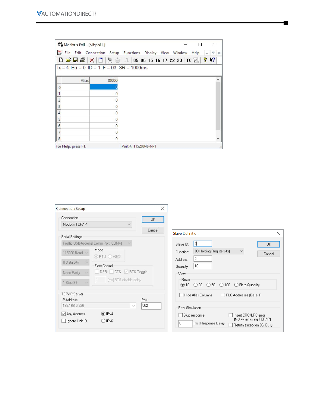
Appendix B: Stride® Modbus Gateway Operating Mode Examples
Click OK in Figure 29 to return to the application interface shown in Figure 32.
Figure 32. Modbus Poll Initial Connection.
The Modbus Poll software will return zero values for all data from the Modbus Gateway Agent until
the Modbus Slave software is connected to the gateway in the next step.
Run the Modbus Slave software on your PC and set the parameters shown in Figure 33.
Figure 33. Modbus Slave Port Configuration. Figure 34. Modbus Slave Definition.
Click OK shown in Figure 33 to return to the Modbus Slave main window.
Select Setup - Slave Definition.
Page B–19Stride® MB Gateway User Manual – 1st Edition Rev. F – April 2021
Page 86
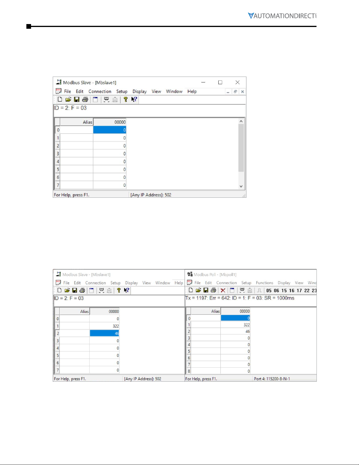
Appendix B: Stride® Modbus Gateway Operating Mode Examples
Enter the Slave ID of the Gateway as shown in Figure 34. This is the Slave ID you assigned to the
Gateway in its “Operating Settings” configuration.
Click OK shown in Figure 34 to return to the application interface shown in Figure 35.
Figure 35. Modbus Slave.
Now let’s experiment with watching data across our network. Enter data in address 2 and address
3 in Modbus Slave and watch as that data is stored in the Agent then read by Modbus Poll, shown
in Figure 36.
Figure 36. Agent Test Result.
Now let’s take a look at the data as it’s stored in the gateway.
In the gateway User Interface, browse to the Data in Gateway Memory page.
Page B–20 Stride® MB Gateway User Manual – 1st Edition Rev. F – April 2021
Page 87
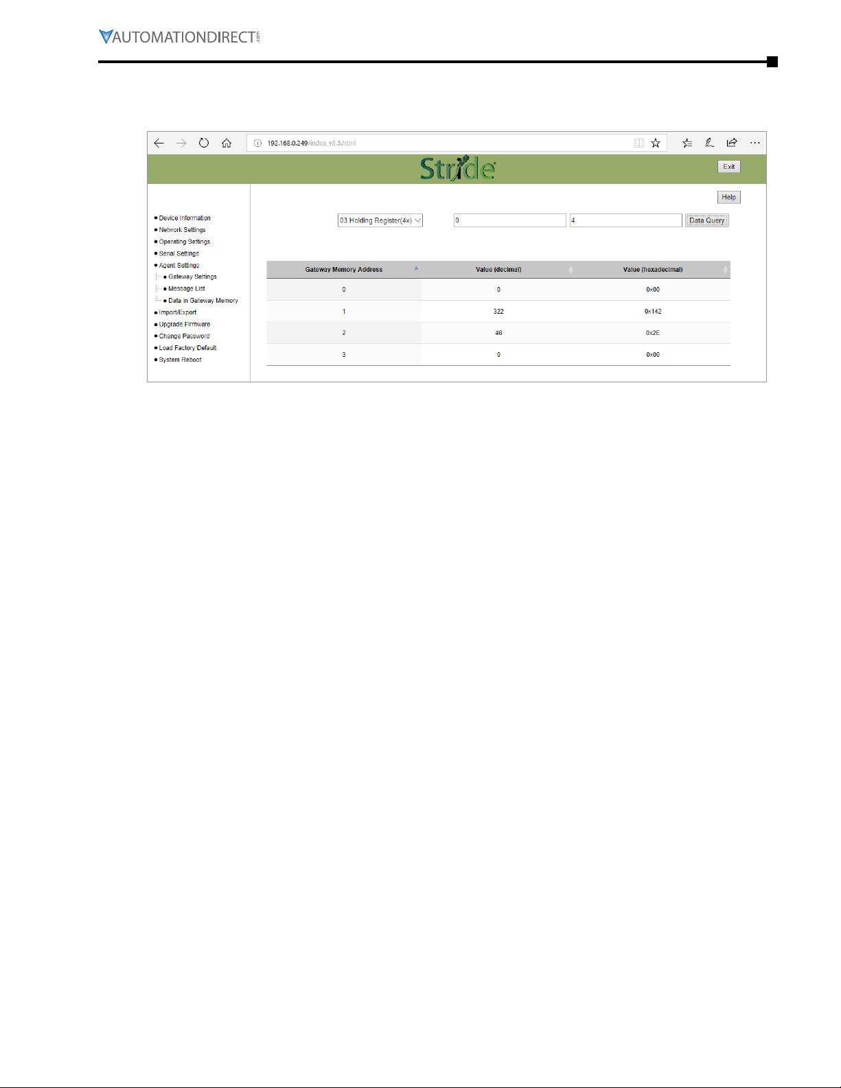
Appendix B: Stride® Modbus Gateway Operating Mode Examples
Enter the Mapping Address (found on the Gateway Settings page) and the quantity of values you’d
like to view. For our example, these values are 0 and 4, respectively.
Figure 37. Data Stored in Gateway Modbus Registers.
Make changes in the Modbus slave user interface and watch the values change in the gateway’s
memory.
Page B–21Stride® MB Gateway User Manual – 1st Edition Rev. F – April 2021
Page 88

Appendix B: Stride® Modbus Gateway Operating Mode Examples
Page B–22 Stride® MB Gateway User Manual – 1st Edition Rev. F – April 2021
Page 89

AppEndix
AppEndix
AppEndix
Modbus Error CodEs
C
C
C
In T
hIs ChapTer
Modbus Error Codes � � � � � � � � � � � � � � � � � � � � � � � � � � � � � � � � � � � � � � � � � C–2
...
Page C–1Stride® MB Gateway User Manual – 1st Edition Rev. F – April 2021
Page 90

Appendix C: Modbus Error Codes
Modbus Error Codes
Error Code Name Explanation
MB-GATEWAY Modbus Error Codes
01 ILLEGAL FUNCTION
02 ILLEGAL DATA ADDRESS The data address received in the query is not an allowable address for the slave.
03 ILLEGAL DATA VALUE A value contained in the query data field is not an allowable value for the slave.
04 SLAVE DEVICE FAILURE An unrecoverable error occurred while the slave was attempting to perform the requested action.
05 ACKNOWLEDGE
06 SLAVE DEVICE BUSY
07 NEGATIVE ACKNOWLEDGE
08 MEMORY PARITY ERROR
The function code received in the query is not an allowable action for the slave. If a Poll Program
Complete command was issued, this code indicates that no program function preceded it.
The slave has accepted the request and is processing it, but a long duration of time will be required
to do so. This response is returned to prevent a timeout error from occurring in the master. The
master can next issue a Poll Program Complete message to determine if processing is completed.
The slave is engaged in processing a long–duration program command. The master should
retransmit the message later when the slave is free.
The slave cannot perform the program function received in the query. This code is returned for
an unsuccessful programming request using function code 13 or 14 decimal. The master should
request diagnostic or error information from the slave.
The slave attempted to read extended memory, but detected a parity error in the memory. The
master can retry the request, but service may be required on the slave device.
Page C–2 Stride® MB Gateway User Manual – 1st Edition Rev. F – April 2021
Page 91

appendix
appendix
appendix
Security conSiderationS for control
SyStemS networkS
D
D
D
In T
hIs ChapTer
Security Considerations for Control Systems Networks � � � � � � � � � � � � � � � � � � � � � � �D-2
...
Page D-1Stride® MB Gateway User Manual – 1st Edition Rev. F – April 2021
Page 92

Appendix D: Security Considerations for Control Systems Networks
Security Considerations for Control Systems Networks
Manufacturers are realizing that to stay competitive, their Automation and Control Systems need
to be more integrated within their plant. The systems often need to be integrated with upstream
Enterprise Data Systems, and even further integrated to allow information to be accessible
across multiple plants, or even through the Internet. This convergence of the IT world with
the Automation World creates challenges in maintaining secure systems and protecting your
investments in processes, personnel, data and intellectual property.
While Automation Networks and Systems have built-in password protection schemes, this is
only one very small step in securing your systems. Automation Control System Networks need
to incorporate data protection and security measures that are at least as robust as a typical
business computer system. We recommend that users of PLCs, HMI products and SCADA systems
perform your own network security analysis to determine the proper level of security required for
you application. However, the Department of Homeland Security’s National Cybersecurity and
Communications Integration Center (NCCIC) and Industrial Control Systems Cyber Emergency
Response Team (ICS-CERT) has provided direction related to network security and safety under an
approach described as “Defense in Depth”, which is published at https://www.us-cert.gov/sites/
default/files/recommended_practices/NCCIC_ICS-CERT_Defense_in_Depth_2016_S508C.pdf.
This comprehensive security strategy involves physical protection methods, as well as process
and policy methods. This approach creates multiple layers and levels of security for industrial
automation systems. Such safeguards include the location of control system networks behind
firewalls, their isolation from business networks, the use of intrusion detection systems, and
the use of secure methods for remote access such as Virtual Private Networks (VPNs). Further,
users should minimize network exposure for all control system devices and such control systems
and these systems should not directly face the internet. Following these procedures should
significantly reduce your risks both from external sources as well as internal sources, and provide
a more secure system.
It is the user’s responsibility to protect such systems, just as you would protect your computer and
business systems. AutomationDirect recommends using one or more of these resources in putting
together a secure system:
•
ICS-CERT’s Control Systems recommended practices at the following web address:
https://ics-cert�us-cert�gov/Recommended-Practices
•
Special Publication 800-82 of the National Institute of Standards and Technology – Guide to
Industrial Control Systems (ICS) Security
https://csrc�nist�gov/publications/detail/sp/800-82/rev-2/final
•
ISA99, Industrial Automation and Control Systems Security
http://www�isa�org/MSTemplate�cfm?MicrositeID=988&CommitteeID=6821
(please note this is a summary and these standards have to be purchased from ISA )
The above set of resources provides a comprehensive approach to securing a control system
network and reducing risk and exposure from security breaches. Given the nature of any system
that accesses the internet, it is incumbent upon each user to assess the needs and requirements of
Security Considerations for Control Systems Networks their application, and take steps to mitigate
the particular security risks inherent in their control system.
Page D-2 Stride® MB Gateway User Manual – 1st Edition Rev. F – April 2021
 Loading...