

Page 1
1-800-633-0405
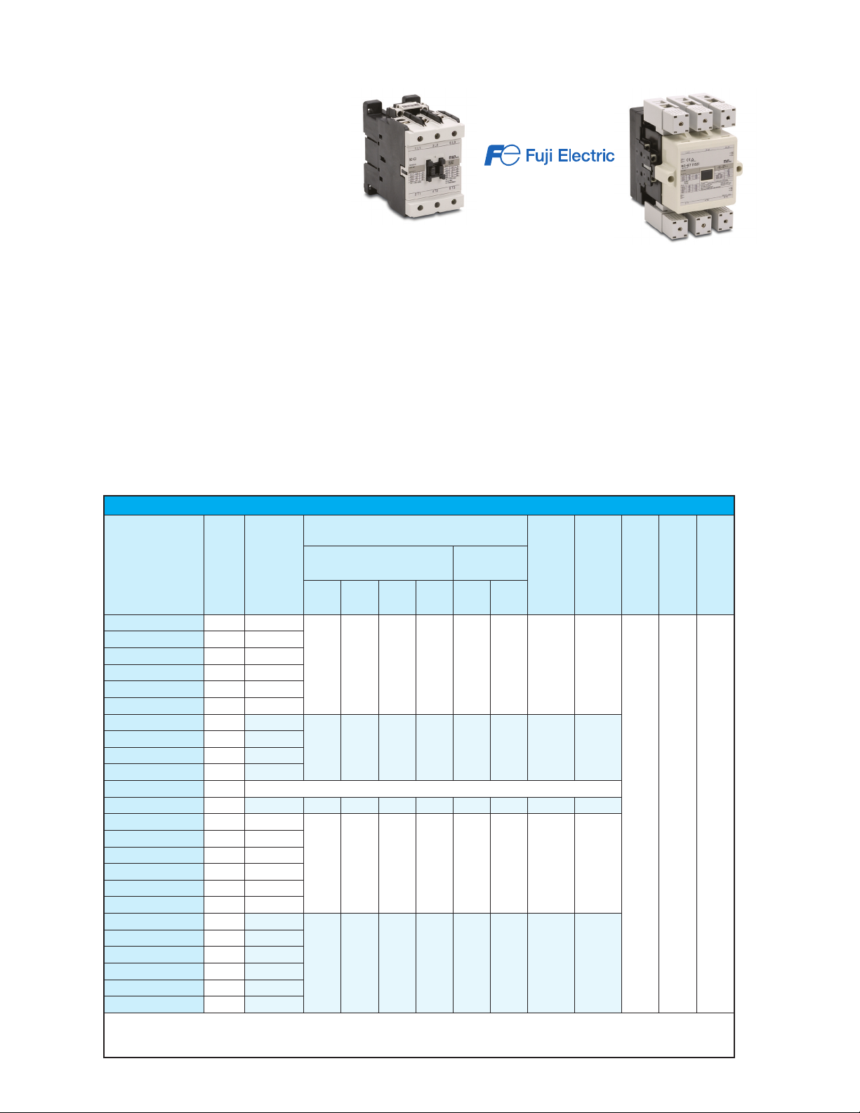
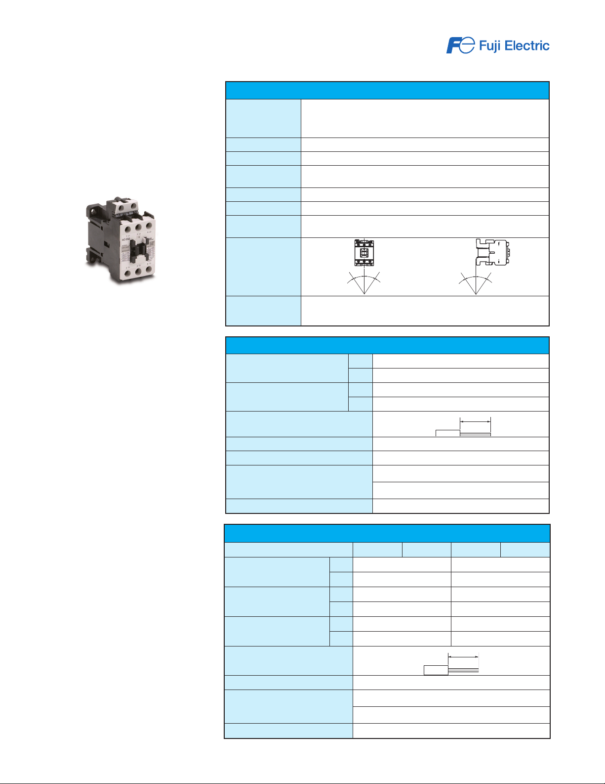
Fuji Duo Series SC-E Contactors
Features
• 5 to 100 hp at 480 VAC
• cULus and CSA approval, CE mark, meets
JIS and IEC standards.
• Models SC-E02-xxx to SC-E4-xxx have
3-pole main circuits and come in three sizes
with widths of 43 mm, 54 mm, and
67 mm.
• Models SC-E1-xxx to SC-E7-xxx employ a
box terminal structure; allowing wires to be
connected directly to the main circuit.
• Has a finger-protection terminal structure
that prevents the exposure of live parts.
• Models SC-E5-xxx to SC-E7-xxx use a
SUPERMAGNETTM (AC-input/DC-output
operation) for high operating reliability
and requires no surge suppressor.
Small Size
• SC-E02-xxx to E05-xxx: 43mm wide
• SC-E1-xxx to E2S-xxx: 54mm wide
• SC-E3-xxx, E4-xxx: 67mm wide
• SC-E5-xxx: 88mm wide
SC-E2S
Safety
• Terminals with finger-touch protection (DIN
57106/VDE 0106 Teil100)
Utility
• Box lug terminal construction
• Long electrical life
• Easy to wire
Environmental
• Low power consumption
• Recycled thermoplastic resin used for
plastic parts.
• The names of materials are indicated on
all major parts to facilitate recycling
For the latest prices, please check AutomationDirect.com.
SC-E7
Standards & Approvals
• UL listed , file E42419, Standard UL 508
• cUL listed, file E42419,
Standard CSA C 22.2 No.14
• VDE 0660
• JIS C 8201-4-1
• IEC 60947-4-1 / EN 60947-4-1
• CE compliant
Optional accessories
• Auxiliary contact blocks
• Coil surge suppression units
• Replacement coils for contactor sizes
SC-E5 and larger
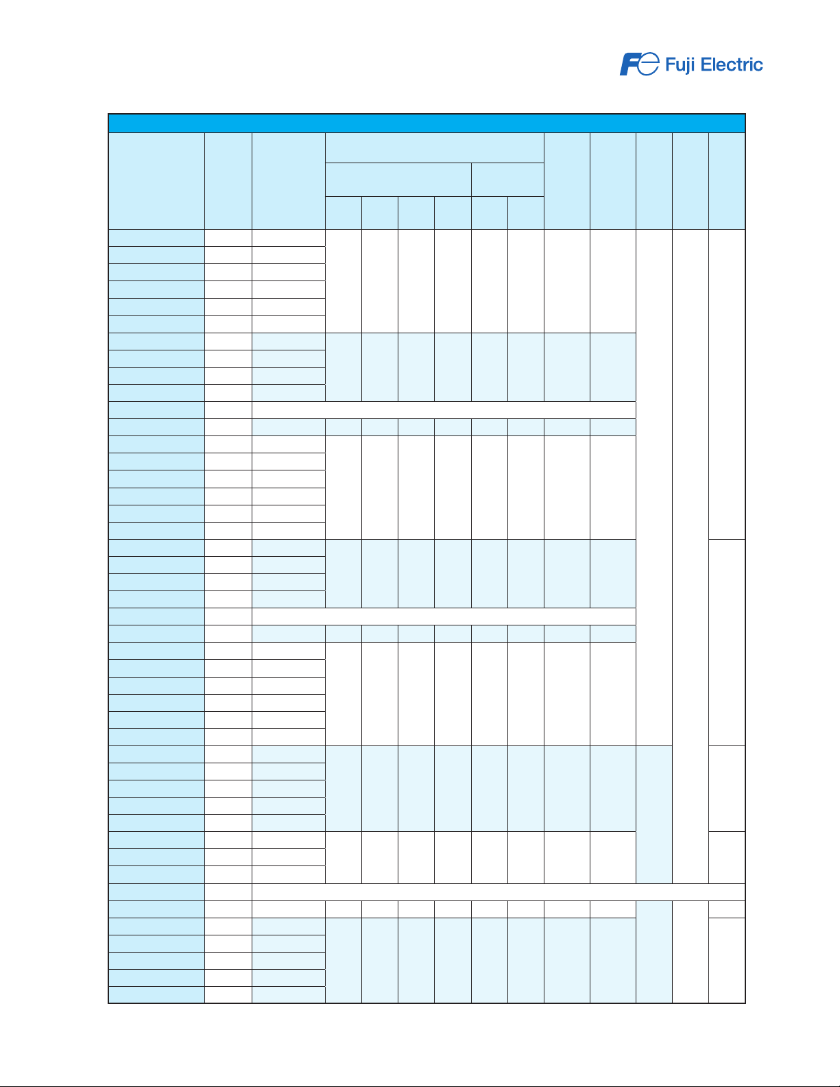
SC-E Series Contactors Specifications - UL and CSA
Nominal Coil
Voltage
Rated Capacity (HP)
550–
600V
1-Phase
Motor
100–
120V
220–
240V
Model Price
SC-E02-24VAC
SC-E02-110VAC
SC-E02-220VAC
SC-E02-440VAC
SC-E02-500VAC
SC-E02G-24VDC
SC-E03-24VAC
SC-E03-110VAC
SC-E03-220VAC
SC-E03-440VAC
SC-E03-500VAC
SC-E03G-24VDC
SC-E04-24VAC
SC-E04-110VAC
SC-E04-220VAC
SC-E04-440VAC
SC-E04-500VAC
SC-E04G-24VDC
SC-E05-24VAC
SC-E05-110VAC
SC-E05-220VAC
SC-E05-440VAC
SC-E05-500VAC
SC-E05G-24VDC
TABLE CONTINUED NEXT PAGE
Notes: 1. AC3 type loads consist of squirrel cage three-phase motors; occasional, limited jogging duty.
2. AC1 non-inductive or slightly inductive loads. Typically resistive loads (i.e. furnaces, ovens, etc.)
$17.00 24VAC
$17.00 110VAC
$17.00 220VAC
$17.00 440-480VAC
$17.00 500-550VAC
$19.00 24VDC
$21.50 24VAC
$21.50 110VAC
$21.50 220VAC
$21.50 440-480VAC
retired Please consider the Fuji Electric SC-E series as comparable replacement
$30.50 24VDC 3 3 7.5 7.5 1/2 2 12 20
$27.00 24VAC
$27.00 110VAC
$27.00 220VAC
$27.00 440-480VAC
$27.00 500-550VAC
$37.50 24VDC
$35.00 24VAC
$35.00 110VAC
$35.00 220VAC
$35.00 440-480VAC
$35.00 500-550VAC
$45.00 24VDC
3-Phase Motor
220–
240V
440–
480V
200V
2 2 5 5 1/3 1 9 20
3 3 7.5 7.5 1/2 2 12 20
5 5 10 10 1 3 18 25
5 7.5 15 15 2 3 25 32
Rated AC-3 Cur-
rent (A) [note 1]
mal Current (A)
[note 2]
Rated AC-1 Ther-
SCCR Ratings
(KA)
5 690 43
Rated Insulation
Voltage (V)
Frame Width (mm)
www.automationdirect.com
Motor Controls
28
Page 2
1-800-633-0405
Fuji Duo Series SC-E Contactors
SC-E Series Contactors Specifications - UL and CSA
Nominal Coil
Voltage
Rated Capacity (HP)
For the latest prices, please check AutomationDirect.com.
Rated AC-3 Cur-
rent (A) [note 1]
mal Current (A)
[note 2]
Rated AC-1 Ther-
SCCR Ratings
(KA)
Rated Insulation
Voltage (V)
(mm)
Frame Width
550–
600V
1-Phase
Motor
100–
120V
Model Price
SC-E1-24VAC
SC-E1-110VAC
SC-E1-220VAC
SC-E1-440VAC
SC-E1-500VAC
SC-E1G-24VDC
SC-E2-24VAC
SC-E2-110VAC
SC-E2-220VAC
SC-E2-440VAC
SC-E2-500VAC
SC-E2G-24VDC
SC-E2S-24VAC
SC-E2S-110VAC
SC-E2S-220VAC
SC-E2S-440VAC
SC-E2S-500VAC
SC-E2SG-24VDC
SC-E3-24VAC
SC-E3-110VAC
SC-E3-220VAC
SC-E3-440VAC
SC-E3-500VAC
SC-E3G-24VDC
SC-E4-24VAC
SC-E4-110VAC
SC-E4-220VAC
SC-E4-440VAC
SC-E4-500VAC
SC-E4G-24VDC
SC-E5-24V
SC-E5-100V
SC-E5-200V
SC-E5-400V
SC-E5-500V
SC-E6-24V
SC-E6-100V
SC-E6-200V
SC-E6-400V
SC-E6-500V
SC-E7-24V
SC-E7-100V
SC-E7-200V
SC-E7-400V
SC-E7-500V
Notes: 1. AC3 type loads consist of squirrel cage three-phase motors; occasional, limited jogging duty.
2. AC1 non-inductive or slightly inductive loads. Typically resistive loads (i.e. furnaces, ovens, etc.)
$42.00 24VAC
$42.00 110VAC
$42.00 220VAC
$42.00 440-480VAC
$42.00 500-550VAC
$49.50 24VDC
$59.00 24VAC
$59.00 110VAC
$59.00 220VAC
$59.00 440-480VAC
retired Please consider the Fuji Electric SC-E series as comparable replacement
$72.00 24VDC 10 15 30 30 3 5 40 60
$72.00 24VAC
$72.00 110VAC
$72.00 220VAC
$72.00 440-480VAC
$72.00 500-550VAC
$85.00 24VDC
$81.00 24VAC
$81.00 110VAC
$81.00 220VAC
$81.00 440-480VAC
retired Please consider the Fuji Electric SC-E series as comparable replacement
$99.00 24VDC 20 25 50 50 5 15 65 100
$83.00 24VAC
$83.00 110VAC
$83.00 220VAC
$83.00 440-480VAC
$83.00 500-550VAC
$102.00 24VDC
$206.00 24VAC/VDC
$206.00 110VAC/VDC
$206.00 220VAC/VDC
$206.00 380-450VAC
$206.00 460-575VAC
$262.00 24VAC/VDC
$262.00 110VAC/VDC
$262.00 220VAC/VDC
Retired Discontinued item. Please consider the Fuji Electric SC-E series as comparable replacements
$262.00 460-575VAC 40 40 75 100 10 20 125 150
$306.00 24VAC/VDC
$306.00 110VAC/VDC
$306.00 220VAC/VDC
$306.00 380-450VAC
$306.00 460-575VAC
3-Phase Motor
220–
240V
440–
480V
200V
7.5 10 25 25 2 3 32 50
10 15 30 30 3 5 40 60
15 20 30 30 3 10 50 65
20 25 50 50 5 15 65 100
25 30 50 50 5 15 80 105
30 30 60 75 7.5 15 105 150
40 40 75 100 10 20 125 150 100
50 50 100 125 15 25 150 200 115
220–
240V
54
5
690
67
88
10
100
10 690
www.automationdirect.com
Motor Controls
29
Page 3
1-800-633-0405
Fuji Duo Series SC-E Contactors
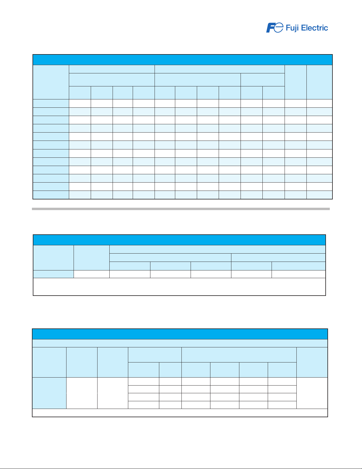
SC-E Series Contactors Specifications - IEC
Rated Capacity (kW) Rated Operating Current (A)
Contactor Type
SC-E02(G)-xxx
SC-E03(G)-xxx
SC-E04(G)-xxx
SC-E05(G)-xxx
SC-E1(G)-xxx
SC-E2(G)-xxx
SC-E2S(G)-xxx
SC-E3(G)-xxx
SC-E4(G)-xxx
SC-E5-xxx
SC-E6-xxx
SC-E7-xxx
3-Phase Motor AC-3 / AC-4 3-Phase Motor AC-3 / AC-4
200240V
2.2 / 2.2 4 / 4 4 / NA 4 / NA 9 / 9 9 / 9 7 / NA 5 / NA 20 20 20 -
7.5 / 7.5 15 / 15 15 / NA 11 / NA 32 / 32 32 / 32 24 / NA 15 / NA 50 50 50 -
18.5 / 18.5 30 / 30 37 / NA 30 / NA 68 / 68 65 / 65 60 / NA 38 / NA 100 100 100 -
22 / 18.5 40 / 30 37 / NA 37 / NA 80 / 68 80 / 65 60 / NA 44 / NA 105 105 105 -
380440V
3 / 3 5.5 / 5.5 5.5 / NA 5.5 / NA 12 / 12 12 / 12 9 / NA 7 / NA 20 20 20 -
4 / 4 7.5 / 7.5 7.5 / NA 7.5 / NA 18 / 18 18 / 18 13 / NA 9 / NA 25 25 25 -
5.5 / 4 11 / 7.5 11 / NA 7.5 / NA 25 / 18 25 / 18 17 / NA 9 / NA 32 32 32 -
11 / 11 18.5 / 18.5 18.5 / NA 15 / NA 40 / 40 40 / 40 29 / NA 19 / NA 60 60 60 -
15 / 11 22 / 18.5 25 / NA 22 / NA 50 / 40 50 / 40 38 / NA 26 / NA 65 65 65 -
30 / 30 55 / 55 5 5/ NA 55 / NA 105 / 105 105 / 105 85 / NA 64 / NA 150 150 150 2NO+2NC
37 / 37 60 / 60 6 0 / NA 60 / NA 125 / 125 125 / 125 90 / NA 72 / NA 150 150 150 2NO+2NC
45 / 45 75 / 75 75 / NA 90 / NA 150 / 150 150 / 150 120 / NA 103 / NA 200 200 200 2NO+2NC
500550V
600690V
200240V
380440V
500550V
600690V
For the latest prices, please check AutomationDirect.com.
Resistive Load
AC-1
200240V
380440V
Rated
Thermal
Current
(A)
Internal
Auxilliary
Contact
Arrangement
Internal Auxiliary Contact Ratings
Internal Auxiliary Contact Ratings - UL and CSA
Frame Size
( note 1 )
E5 to E7-xxx
Notes:
1. E02(G) to E4(G) do not have internal auxiliary contact.
2. NEMA ICS 5-2000. For more information, refer to Control Circuit Contact Electrical Ratings, see page MRC-111.
Rated
Insulation Voltage (V)
690 A600 7200 720 Q300 69
Based on IEC 60974-4-1, EN 60947-4-1, JIS C 8201-4-1
Frame Size
( note 1 )
E5 to E7-xxx
Note 1: E02(G) to E4(G) do not have internal auxiliary contact.
Rated
Insulation
Voltage (V)
690 10
NEMA ICS 5-2000 Ratings ( note 2 )
AC Ratings DC Ratings
Designation Making VA Breaking VA Designation Making/Breaking VA
Internal Auxiliary Contact Ratings - IEC, JIS
Rated
Thermal
Current (A)
Making and Breaking
Capacity (A)
AC Voltage Amps AC Voltage
120V 60 120V 6 24V 3
220V 30 220V 3 48V 1.5
440V 15 440V 1.5 110V 0.55
600V 12 600V 1.2 220V 0.27
Rated Operational Current (A)
AC-15
(Ind. load)
DC Voltage
DC-13
(Ind. load)
Minimum
Operating
Voltage and
Current
5VDC, 3mA
www.automationdirect.com
Motor Controls
30
Page 4
1-800-633-0405
Fuji Duo Series SC-E Contactors
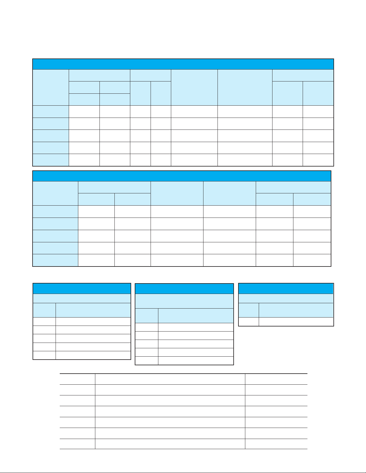
Coil Characteristics
AC Coil Characteristics
For the latest prices, please check AutomationDirect.com.
Frame Size
E02 to E05-xxx
E1 to E2S-xxx
E3, E4-xxx
E5-xxx
E6, E7-xxx
Frame Size
E02G to E05G-xxx
E1G to E2SG-xxx
E3G, E4G-xxx
E5-xxx
E6, E7-xxx
Power Consumption (VA) Power Loss (W)
Inrush Sealed
50Hz 60Hz
50/60Hz 50/60Hz
90/95 9/9 2.7 2.8
120/135 12.7/12.4 3.6 3.8
180/190 13.3/13.4 4.5 5
80/95 4/4.6 3.2 3.6
190/230 4.9/5.8 3.4 3.7
DC Coil Characteristics
Power Consumption (W)
Pick-Up Voltage (V) Drop-Out Voltage (V)
Inrush Sealed
7 7
9 9
12 12
90 2.8
225 3.2
Pick-Up Voltage (V) Drop-Out Voltage (V)
0.85 - 1.1 x U.S.
rated coil voltage
0.85 - 1.1 x U.S.
rated coil voltage
0.85 - 1.1 x U.S.
rated coil voltage
0.85 - 1.1 x U.S.
rated coil voltage
0.8 - 1.1 x U.S.
rated coil voltage
0.85 - 1.1 x U.S.
rated coil voltage
0.85 - 1.1 x U.S.
rated coil voltage
0.85 - 1.1 x U.S.
rated coil voltage
0.85 - 1.1 x U.S.
rated coil voltage
0.8 - 1.1 x U.S.
rated coil voltage
0.2 - 0.75 x U.S.
rated coil voltage
0.2 - 0.75 x U.S.
rated coil voltage
0.2 - 0.75 x U.S.
rated coil voltage
0.2 - 0.75 x U.S.
rated coil voltage
0.1 - 0.65 x U.S.
rated coil voltage
0.1 - 0.75 x U.S.
rated coil voltage
0.1 - 0.75 x U.S.
rated coil voltage
0.1 - 0.75 x U.S.
rated coil voltage
0.1 - 0.75 x U.S.
rated coil voltage
0.1 - 0.65 x U.S.
rated coil voltage
Operating Time (ms)
Coil ON to
Contact ON
9-20 5-16
10-17 6-13
10-18 8-18
39-45 27-33
31-37 30-36
Operating Time (ms)
Coil ON to
Contact ON
45-49 10-26
40-50 8-17
60-70 14-21
35-41 26-32
28-34 27-33
Coil OFF to
Contact OFF
Coil OFF to
Contact OFF
Operating Coil
AC Coil, SC-E02-xxx to SC-E4-xxx
Voltage
Code
24VAC 24VAC 50Hz / 24-26VAC 60Hz
110VAC 100-110VAC 50Hz / 110-120VAC 60Hz
220VAC 200-220VAC 50Hz / 220-240VAC 60Hz
440VAC 415-440VAC 50Hz / 440-480VAC 60Hz
500VAC 480-500VAC 50Hz / 500-550VAC 60Hz
Coil Operating Voltage / Frequency
Performance Data
Frame size Making current (A)Breaking current (A)Operating cyclesDurability (operations)
SC-E02 108108 90 90 1800 2 million 10 million
SC-E03 144144 120120 1800 1.5 million 10 million
SC-E04 216216 180180 1800 1.5 million 10 million
SC-E05 250250 200200 1200 1.5 million 10 million
SC-E1384 384320 320 1200 1.5 million 10 million
SC-E2480 480400 400 1200 1.5 million 10 million
SC-E2S 500500 400400 1200 1.5 million 10 million
SC-E3816 780680 650 1200 1.5 million 5 million
SC-E4816 800680 650 12001 million 5 million
SC-E5 1260 12601050105012001 million 5 million
SC-E6 1500 15001250125012001 million 5 million
SC-E7 1800 18001500150012001 million 5 million
www.automationdirect.com
220V440V 220V 440V per hour Electrical Mechanical
Operating Coil
AC/DC Coil (SUPERMAGNET),
SC-E5-xxx to SC-E7-xxx
Voltage
Code
24V 24-25VAC 50/60Hz; 24VDC
100V 100-127VAC 50/60Hz; 100-120VDC
200V 200-250VAC 50/60Hz; 200-240VDC
400V 380-450VAC 50/60Hz
500V 460-575VAC 50/60Hz
Coil Operating Voltage / Frequency
Operating Coil
DC Coil, SC-E02G-xxx to SC-E4G-xxx
Voltage
Code
24VDC 24VDC
Coil Operating Voltage
Motor Controls
31
Page 5
10 mm
11 mm
1-800-633-0405
Fuji Duo Series SC-E Contactors
For the latest prices, please check AutomationDirect.com.
Standard operating
conditions
The magnetic contactors are manufactured for use in the standard operating
conditions given in the table.
Wiring
Be sure to perform wiring correctly with
reference to the wiring diagrams. Main
terminals for models SC-E02 to SC-E7
are wired using solid wires or stranded
wires. Stranded wires or flexible stranded
wires can be connected by twisting them
together and crimping a sleeve (ferrule)
onto them before connecting.
Tightening torque
If wires are not tightened sufficiently, they
may become hot or loosen, resulting in a
fire, short-circuit, electric shock, or other
potentially dangerous situation. Tighten
wires to the torques specified in these
tables.
Standard Operating Conditions
Ambient
Temperature
Humidity
Altitude
Atmosphere
Vibration
Shock
Mounting
Mounting Angle
Standard
No sudden temperature changes resulting in condensation or icing
(The average temperature over a 24-hour period must not exceed 35°C)
No excessive dust, smoke, corrosive gases, flammable gases, steam, or salt
mounting (SC-E02 to SC-E4), screw mounting
30˚
Operating: -5 to 55°C
Storage: -40 to 65°C
45 to 85%RH
2000m or lower
10 to 55Hz 15m/s
50m/s
35mm IEC DIN rail
2
2
30˚
30˚
IEC 947-4-1, EN 60947-4-1, VDE 0660
JIS C 8201-4-1, JEM 1038
UL 508, file E42419; CSA C22.2, file 20479
30˚
Wire Sizes, Tightening Torques - Control Circuit
Solid or Stranded Wire (mm²)
AWG
Insulation Stripping Length
Fork Terminal
Terminal Screw Size
Tool
Tightening Torque (N.m)
One
Two
One
Two
0.75 to 2.5 (1 to 1.6 mm diameter)
0.75 to 2.5 (1 to 1.6 mm diameter)
18 to 14
18 to 14
0.39 in
Max. 7.7mm wide
M3.5
Phillips screwdriver, H-type, No. 2 (ISO 8764);
ADC part number DN-SP1 or DN-SP2
Flat-blade screwdriver, 1 x 5.5 x L-type, B (ISO 2830);
ADC part number DN-SS5
0.8 to 1
Wire Sizes, Tightening Torques - Main Circuit
Contactor Type SC-E02-xxx SC-E03-xxx SC-E04-xxx SC-E05-xxx
Solid Wire (mm²)
Stranded Wire (mm²)
AWG
One
Two
One
Two
One
Two
0.75 to 4 0.75 to 6
1 to 4 1.5 to 6
0.75 to 4 0.75 to 6
1 to 4 1.5 to 6
12 max. 10 max.
12 max. 10 max.
www.automationdirect.com
Insulation Stripping Length
Terminal Screw Size
Tool
Tightening Torque (N.m)
0.43 in
M4
Phillips screwdriver, H-type, No. 2 (ISO 8764);
ADC part number DN-SP1 or DN-SP2
Flat-blade screwdriver, 1 x 5.5 x L-type, B (ISO 2830);
ADC part number DN-SS5
1.2 to 1.5
Motor Controls
32
Page 6
1-800-633-0405
For the latest prices, please check AutomationDirect.com.
Fuji Duo Series SC-E Contactors
Wire Sizes, Tightening Torques - Main Circuit
Contactor Type SC-E1, E2, E2S-xxx SC-E3, E4-xxx SC-E5, E6-xxx SC-E7-xxx
Top-Only
Connection
Bottom-Only
Connection
Solid or stranded wire (mm 2)
Flexible stranded wire
with sleeve (mm 2)
1
Flexible stranded wire
without sleeve (mm 2)
AWG
Solid or stripping length (mm)
Single stranded wire (mm 2)
Flexible stranded wire
with sleeve (mm 2)
1
Flexible stranded wire
without sleeve (mm 2)
AWG
Sheath stripping length (mm)
Solid or stranded wire
1
(mm 2)
1
1
Top/
bottom
0.75 to 35 1.5 to 70 4 to 70 4 to 120
0.75 to 25 1.5 to 50 2.5 to 50 2.5 to 95
0.75 to 25 1.5 to 50 4 to 50 4 to 95
18 to 2 16 to 2/0 12 to 2/0 12 to 250MCM
15 19.5 26.5 28.5
0.75 to 25 1.5 to 50 4 to 70 4 to 120
0.75 to 16 1.5 to 35 2.5 to 50 2.5 to 95
0.75 to 16 1.5 to 35 4 to 50 4 to 95
18 to 3 16 to 1/0 12 to 2/0 12 to 250MCM
12.5 16 26.5 28.5
0.75 to 25 1.5 to 50 4 to 70 4 to 120
Top/Bottom
Connection
Flexible stranded wire with
sleeve (mm 2)
Flexible stranded wire
1
without sleeve (mm 2)
AWG
Tool
Tightening Torque (Nm)
Self-locking Torque (Nm)
Note 1: Stranded wire (0 to 25mm2) consists of 7 wires or less.
Stranded wire (35 to 120mm2) consists of 19 wires or less.
Flexible stranded wire consists of more number wires than
the above.
2
Top/
bottom
Top/
bottom
Top/
bottom
0.75 to 16 1.5 to 35 2.5 to 50 2.5 to 95
0.75 to 16 1.5 to 35 4 to 50 4 to 95
18 to 3 16 to 1/0 12 to 2/0 12 to 250MCM
Phillips screwdriver, H-type, No.2
(ISO 8764);
ADC part number DN-SP1 or
DN-SP2
Flat-blade screwdriver, 1 x 5, 5xL-
type, B (ISO 2830);
ADC part number DN-SS5
2.5 8 10
1 2
Note 2: T he tightening bolt must be loosened in order to insert the wire. However, stop
loosening the bolt when the anti-drop attachment on the bottom of the bolt reaches the
top edge of the terminal. If a torque exceeding that given in the table is applied in this
state, the retaining bracket may loosen.
Hex. wrench 4 (ISO 2936)
www.automationdirect.com
Motor Controls
33
Page 7
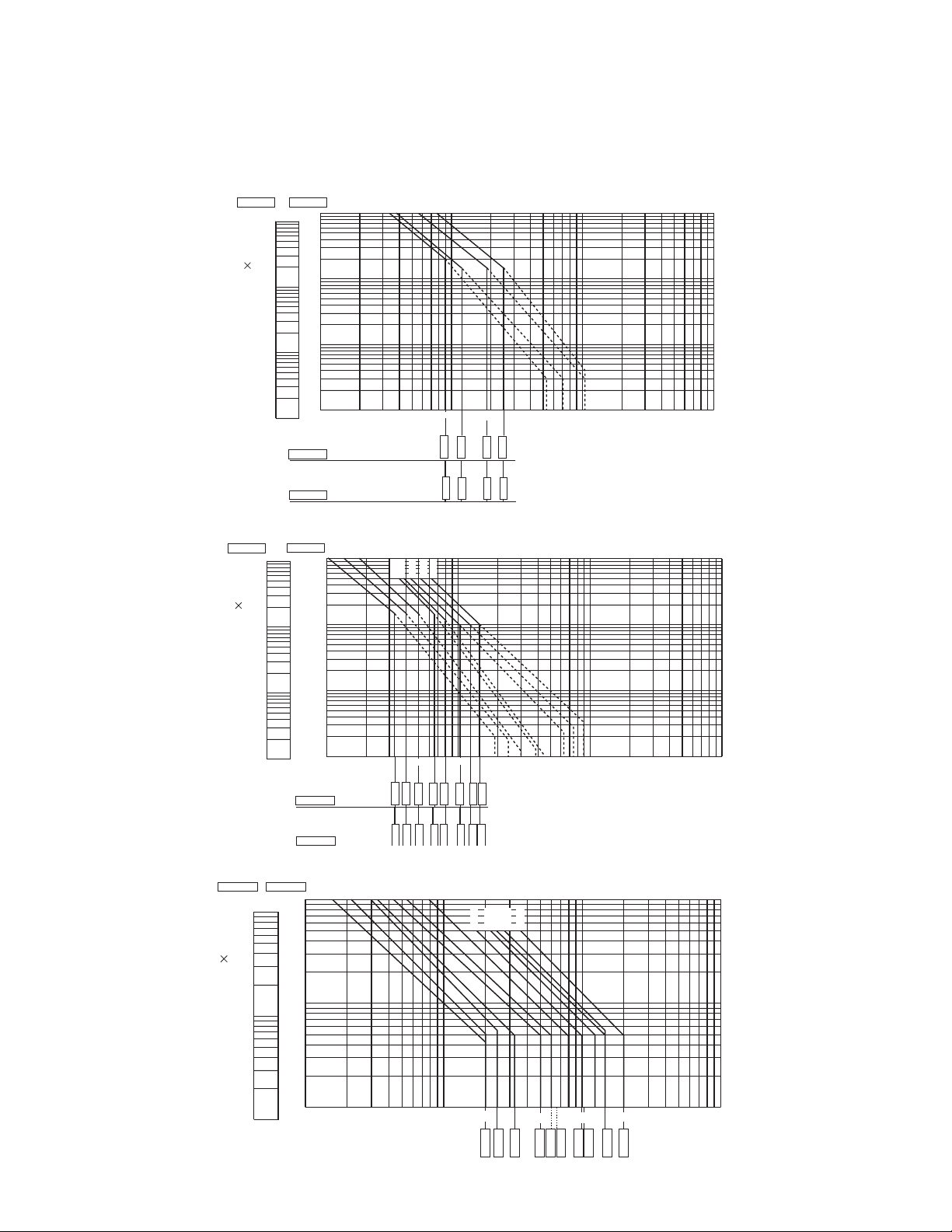
AC-3 duty / SC-E1 to SC-E7-xxx
A
Breaking current (A)
A
C-3 duty / SC-E02 to SC-E05-xxx
1-800-633-0405
Fuji Duo Series SC-E Contactors
Electrical durability
For the latest prices, please check AutomationDirect.com.
200 - 240V
200 - 240V
)
3
Make/break operations ( 10
380 - 440V
10000
10000
)
3
Make/break operations ( 10
10000
5000
3000
2000
1000
500
300
200
100
5000
5000
3000
3000
2000
2000
1000
50
30
20
10
1000
500
500
300
300
200
200
100
100
50
50
30
30
20
20
10
10
3-phase motor capacity (kW)
and full-load current (A)
1 2 3
3-phase motor capacity (kW)
and full-load current (A)
380 - 440V
200 - 240V
380 - 440V
10000
5000
3000
2000
1000
500
300
200
100
50
30
20
10
10 20 30
380 - 440V
SC-E1
SC-E2
SC-E2S
SC-E02
32A
SC-E03
SC-E3
15kW
SC-E4
40A
18.5kW
SC-E5
50A
SC-E04
SC-E6
22kW
SC-E7
65A
30kW
SC-E05
20 30 50 100 200300 500 1000
105
9A
12A
18A
4kW
2.2kW
80A
40kW
10050
105A
25A
5.5kW 7.5kW
11kW
3kW
4kW
5.5kW
200 300 500 1000 2000 3000 5000 10000
125A
150A
55kW
60kW
75kW
Breaking current (A)
Breaking current (A)
www.automationdirect.com
200 - 240V
7.5kW
C-1 duty / SC-E02 to SC-E7-xxx
200 - 240V
380 - 440V
10000
)
3
5000
3000
2000
1000
Make/break operations ( 10
10000
500
300
200
100
5000
3000
2000
1000
500
300
200
100
1 2 3
SC-E02
SC-E03
SC-E04
SC-E05
SC-E1
37kW
22kW
30kW
18.5kW
11kW
15kW
SC-E2
SC-E2S
SC-E3
20 30 50 100200 300 500 1000
105
45kW
SC-E4
20A
SC-E5
25A
SC-E6
32A
SC-E7
50A
65A
60A
100A
105A
150A
200A
Motor Controls
34
Page 8

1-800-633-0405
Fuji Duo Series SC-E Contactors
Accessories
Optional accessories
For the latest prices, please check AutomationDirect.com.
SZ-Z coil surge
SZ-AS1T auxiliary con-
tact block
SZ-A22T auxiliary con-
tact block
suppression unit
Auxiliary contact blocks
with terminal covers
Maximum auxiliary contact blocks: 2
side mounted (1 per side) OR 1 front
mounted. The front and side blocks
cannot be mounted together on the
same contactor.
Caution on use:
1. Front mounting auxiliary contact
block and side mounting block
cannot be attached to one contactor at the same time.
2. Only one front mounting block can
be attached to one contactor.
3. Where interlock unit is already attached, side mounting auxiliary
contact block can be attached on
one side only.
SC-E Contactor
SZ-AS1T auxiliary con-
tact block
SZ-A22T SZ-A11T SZ-AS1T SZ-AS2T
Auxiliary Contact Blocks with Terminal Covers
Part Number Price Applicable Contactor Mounting
SZ-A22T
SZ-A20T
SZ-A11T
SZ-AS1T
SZ-AS2T
$14.50
$9.00
$9.00 1NO + 1NC
$14.50 SC-E02(G)-xxx to E4(G)-xxx
$14.50
SC-E02(G)-xxx to E4(G)-xxx Front mounting
SC-E5, E6, E7-xxx, SC-N4, N5,
N6, N7, N8, N10, N11, N12, SC-
E5(G)-xxx to E7(G)-xxx
Side mounting
Number of
Contacts
Contact
Arrangement
4 2NO + 2NC
2
2 1NO + 1NC
2 1NO + 1NC
2NO
Accessory Auxiliary Contact Ratings - UL and CSA
NEMA ICS 5-2000 Ratings ( note 1 )
AC Ratings DC Ratings
Designation Making VA Breaking VA Designation Making/Breaking VA
A600 7200 720 Q300 69
For more information, refer to Control Circuit Contact Electrical Ratings, page MRC-111
Accessory Auxiliary Contact Ratings - IEC and JIS continued on next page.
www.automationdirect.com
Motor Controls
35
Page 9

IC-circuit
1-800-633-0405
Fuji Duo Series SC-E Contactors
Accessories
Accessory Auxiliary Contact Ratings - IEC and JIS
Rated
Thermal
Current (A)
10
Making and
Breaking Capacity
at AC (A)
120V 60 120V 6 24V 3
220V 30 220V 3 48V 1.5
440V 15 440V 1.5 110V 0.55
600V 12 600V 1.2 220V 0.27
Rated operational current (A)
AC DC
Voltage AC-15 (Ind. load) Voltage DC-13 (Ind. load)
For the latest prices, please check AutomationDirect.com.
Minimum
Operating Voltage
and Current
5VDC, 3mA
Coil surge suppression units
SZ-Z1 SZ-Z37
Suppress surge voltage due to contactor
ON-OFF operations; easily connect to
contactor coil terminals.
Important: When driving 24VDC Fuji contactors
with a PLC solid-state output, we recommend
using diode terminal block part number
DN-D10DR-A or ZL-TSD8-24. Please see
application note AN-MISC-032 for additional
information located on Automationdirect.com/
technotes.
Coil Surge Suppression Units
Part Number Price
SZ-Z1
SZ-Z2
SZ-Z31
SZ-Z32
SZ-Z4
SZ-Z5
SZ-Z34
SZ-Z35
SZ-Z36
SZ-Z37
Applicable Contactor
AC Operated DC Operated
$11.50
SC-E02-xxx to E05-xxx
$11.50 100-250V AC/DC
$15.50
$15.50 100-250V AC/DC
$12.50
$13.00 100-250V AC/DC
$15.50
$15.50 100-250V AC/DC
$15.50
$15.50 100-250V AC/DC
SC-E1-xxx to -E4xxx
SC-E02-xxx to E05-xxx
SC-E1-xxx to E4-xxx -
-
SC-E02G-xxx to
E05G-xxx
SC-E1G-xxx to
E4G-xxx
SC-E02G-xxx to
E05G-xxx
SC-E1G-xxx to
E4G-xxx
SC-E02 to E05
SC-E1 to E4
Note: Super Magnet Coils on SC-E5, SC-E6, and SC-E7 contactors have internal surge suppression.
See diagram below.
Power
supply
AC or DC
Surge
suppression
circuit
Rectifier
circuit
Voltage
detector
Closing
signal
circuit
Sealing
signal
circuit
Operating Coil
Voltage
24-48V AC/DC
24-48V AC/DC
24-48V AC/DC
24-48V AC/DC
24-48V AC/DC
380-440V AC/DC
380-440V AC/DC
Power
switching
circuit
Device
varistor
capacitor /
resistor
COILINPUT
Replacement contactor coils
SC-E Series Replacement Contactor Coils
Part Number Price Applicable Contactor Coil Voltage
SZ-GSN6-100
SZ-GSN5-200
SZ-GSN6-200
SZ-GSN5-24
SZ-GSN6-24
www.automationdirect.com
Retired
Retired
Retired
Retired
Retired
Discontinued item. No replacement available.
Motor Controls
36
Page 10

1-800-633-0405
Fuji Duo Series SC-E Accessories
Connection kits for reversing SC-E contactors
For the latest prices, please check AutomationDirect.com.
SZ-ERW1A
Line Side
Wiring
SZ-ERW2D SZ-ERW3A
Load Side
Wiring
SZ-ERW1B SZ-ERW1D
Load Side
Wiring
Line Side
Wiring
Load Side
Wiring
SZ-ERW3B
Load Side
Wiring
SZ-ERW2A
Line Side
Wiring
Load Side
Wiring
SZ-ERW2B
Load Side
Wiring
SZ-ERW3D
Connection Kits
Part Number Price Description Use with Contactors
SZ-ERW1A
SZ-ERW1B*
SZ-ERW1D
SZ-ERW2A
SZ-ERW2B*
SZ-ERW2D
SZ-ERW3A
SZ-ERW3B*
SZ-ERW3D
* When using the SZ-ERWxB, a TK-E thermal overload relay must be separately mounted and wired using an SZ-HxE base. To
assemble a TK-E overload directly to the contactor use a SZ-ERWxD load side connection kit.
$5.75 Line side reversing connection kit.
$5.75 Load side reversing connection kit. For wiring load side when using contactors only or with a MMS device.
$5.75 Load side reversing connection kit. For wiring load side when using two contactors with a thermal overload relay.
$11.50 Line side reversing connection kit.
$11.50 Load side reversing connection kit. For wiring load side when using contactors only or with a MMS device.
$11.50 Load side reversing connection kit. For wiring load side when using two contactors with a thermal overload relay.
$20.50 Line side reversing connection kit.
$20.50 Load side reversing connection kit. For wiring load side when using contactors only or with a MMS device.
$20.50 Load side reversing connection kit. For wiring load side when using two contactors with a thermal overload relay.
SC-E02-xxx to SC-E05-xxx
SC-E1-xxx to SC-E2S-xxx
SC-E3-xxx to SC-E4-xxx
Mechanical interlock unit
Part
Number
SZ-RM
SZ-RM
NOTE: Mechanical interlock unit cannot be used with SC-E5-xxx through E7-xxx contactors.
Parts for reversing Fuji SC-E contactors
• SC-E (Contactors - qty. 2)
• SZ-ERWxA (Line side connection kit - qty. 1)
• SZ-ERWxB* (Load side connection kit - qty. 1)
• SZ-RM (Mechanical interlock - qty. 1)
• SZ-AxxT (Auxiliary contact blocks - qty. 1)
www.automationdirect.com
Mechanical Interlock Unit
Price Description Use with Contactors
Used when building a reversing starter. Prevents both contactors
$14.50
from being pulled in at once.
SC-E02-xxx to SC-E4-xxx
Motor Controls
37
Page 11
SC-E02, E03, E04, E05-xxx
: 35 60 : 35 (48 to) 52
SC-E1, E2, E2S-xxx
: 45 75 : 45 (38 to 46) 80
SC-E3, E4-xxx
: (55 to) 60 90 : (54 to) 60 90
1-800-633-0405
Fuji Duo Series SC-E Contactors
For the latest prices, please check AutomationDirect.com.
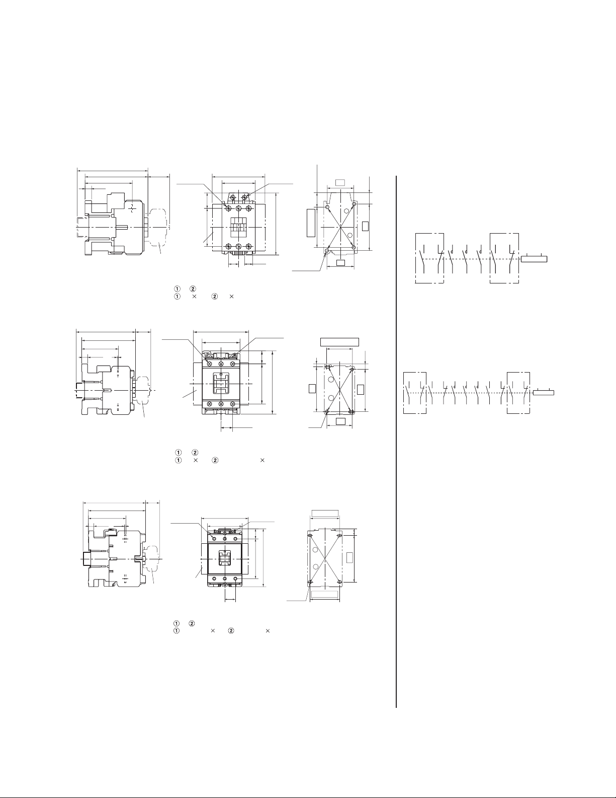
Dimensions (mm)
Contactors
(Rail height 15)
91
81
61
8.5
Weight: 0.33 kg
Mass: 0.33kg
106 (Rail height 15)
96
65.5
10.5
Weight: 0.58 kg
Mass : 0.58kg
2
(28)
(28)
2
*
2
*
Main
terminal
2
*
13
*
16.5
(68)
43
1
1
*
Coil terminal
M3.5
10.5
Coil terminal
M3.5
18.5
90
57
80
2
*
Main
terminal M4
49 20
1
*
Use the two mounting holes on a diagonal line
or to mount contactor
(79)
54
1
*
Use the two mounting holes on a diagonal line
or to mount contactor
18.5(to 20.5)
(48 to)52
Mounting hole
2-M4
Panel drilling
5
80
Mounting hole
2-M4
Panel drilling
34
1
2
35
45(38 to 46)
2
1
45
75
9.5
14.5
60
Wiring diagrams
Contactors
SC-E02 to E05-xxx
SC-E1 to E4-xxx
SC-E02G to E05G-xxx
SC-E1G to E4G-xxx
SC-E2S, E2SG-xxx
1
*
53 61 1/L1 3/L2 5/L3 83 71
*1 In case of aux. contact 2NO+2NC
SC-E5, E6, E7-xxx
1
*
53 61 13 21 1/L1 3/L2 5/L3 43 31 83 71
1
*
In case of aux. contact 4NO+4NC
1
*
6/T3 4/T2 2/T1
72846254
6/T3 4/T2 2/T1
1
*
A1 A2
A1 A2
7284324422146254
2
121 (Rail height 15)
72.5
10.5
Mass: 1.1kg
Weight: 1.1 kg
111
2.5
(28)
*
2
*
www.automationdirect.com
1
Coil terminal
Main
terminal
1
*
Use the two mounting holes on a diagonal line
or to mount contactor
(91)
67
20.5
*
M3.5
19.5
77
112
Mounting hole
2-M4
Panel drilling
(54 to)60
2
1
(55 to)60
90 13
Motor Controls
38
Page 12

SC-E6-xxx
SC-E02G,
35 60 : 35 (48 to) 52
SC-E5-xxx
*
*
Front mounting aux. contact block
1-800-633-0405
Fuji Duo Series SC-E Contactors
Dimensions (mm)
Contactors
For the latest prices, please check AutomationDirect.com.
132
77
32.7
4
Weight: 2.0 kg
Mass: 2.0kg
1
Side mounting aux. contact block
2
138
77
4
38.8
Mass: 2.6kg
Weight: 2.6 kg
Main
terminal
Auxiliary
terminal
M3.5
Main
terminal
Auxiliary
terminal
M3.5
(111)
88
32
(123)
100
*
32
Coil terminal
1
M3.5
13.5
Coil terminal
M3.5
1
*
129
155
143 13.5
169
Panel drilling
70
Mounting hole
2-M4
75
Panel drilling
(80 to)90
Mounting hole
2-M5
110
SC-E7-xxx
140
76.8
38.8
Weight: 2.9 kg
Mass: 2.9kg
118 (Rail height 15)
8.5
Weight: 0.59 kg
Mass: 0.59kg
Main
terminal
Auxiliary
terminal
M3.5
E03G, E04G, E05G-xxx
2
*
108
88
(28)
2
*
Coil terminal
M3.5
1
(138)
*
115
14.5
146
175
35
Main
terminal
M4
49 20
1
*
Use the two mounting holes on a diagonal line
or to mount contactor
13
(68)
43
1
*
10.5
Coil terminal
M3.5
80
18.5(to 20.5)
(48 to)52
Mounting hole
2-M4
Panel drilling
(80 to)90
Mounting hole
2-M5
Panel drilling
34
1
2
35
110
14.5
60
www.automationdirect.com
Motor Controls
39
Page 13

SC-E1G, E2G, E2SG-xxx
*
*
Front mounting aux. contact block
SC-E3G, E4G-xxx
SC-E3G, E4G-xxx
67
112
54 62 72 84
1-800-633-0405
Fuji Duo Series SC-E Contactors
Dimensions (mm)
Contactors
For the latest prices, please check AutomationDirect.com.
2
130 (Rail height 15)
121.5
91
10.5
Weight: 0.79 kg
Mass: 0.79kg
1
Side mounting aux. contact block
2
140 (Rail height 15)
10.5 2.5 67
Weight: 1.4 kg
Mass: 1.4kg
2
130
91.5
*
(28)
Main
terminal
1
*
2
*
(28)
2
*
Main
terminal
2
*
1
*
Side mounting aux. contact block
2
*
Front mounting aux. contact block
1
*
(79)
54
Use the two mounting holes on a diagonal line
or to mount contactor
16.5
Coil terminal
M3.5
18.5
90
57
Mounting hole
2-M4
Panel drilling
45(38 to 46)
5
2
80
1
45
9.5
75
Panel drilling
Coil terminal
1
(91)
*
M3.5
19.5
77
112
1
*
20.5
Use the two mounting holes on a diagonal line
or to mount contactor
Mounting hole
2-M4
(54 to)60
2
1
(55 to)60
13
90
Dimensions-mm
Auxiliary contact blocks - front mounting
SZ-A22T, A20T, A11T for SC-E02 (G)-xxx to E4 (G)-xxx
M3.5
11
Approx
3
525
SZ-A20T , A11T
Type
SC-E02, E03, E04, E05-xxx
SC-E1, E2, E2S-xxx
SC-E3, E4-xxx
SC-E02G, E03G, E04G, E05(G)-xxx
SC-E1G, E2G, E2SG-xxx
7.7
10
43
7.7
M3.5
28
49
10
24
A22T Mass: 36g
Weight: 36 g
Weight: 20 g
Mass: 20g
Wiring diagrams
SZ-A22T, A20T, A11T
53 63
Contactor with aux. contact block
AC
Approx
3
49
28
A
43
54
67
43
54
B
80
90
112
80
90
C
109
124
139
136
149.5
A
B
B
2NO
54 64
53 61
1NO+1NC
54 62
53 61 71 83
2NO+2NC
www.automationdirect.com
Motor Controls
40
Page 14
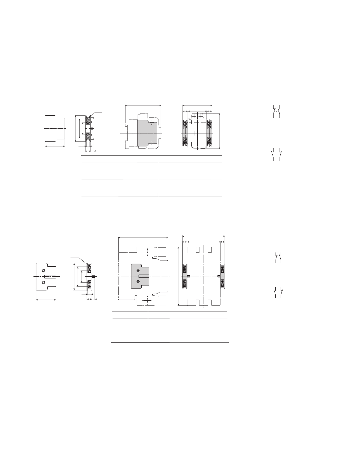
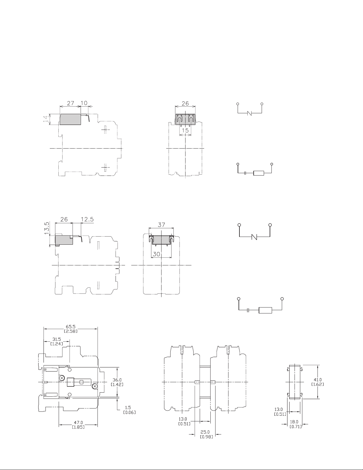
1 N.O. + 1 N.C.
SZ-AS1T for SC-E02(G)-xxx to E4(G)-xxx
SZ-AS2T for SC-E5 to E7-xxx
115
1-800-633-0405
Fuji Duo Series SC-E Contactors
For the latest prices, please check AutomationDirect.com.
Dimensions (mm)
Auxiliary contact blocks - side mounting
Contactor with aux. contact block
C
M3.5
43
28
59.5
45
Weight: 28 g
Mass: 28g
7.7
12 7.5
Type
SC-E02, E03, E04, E05-xxx
SC-E1, E2, E2S-xxx
SC-E3, E4-xxx
SC-E02G, E03G, E04G, E05(G)-xxx
SC-E1G, E2G, E2SG-xxx
SC-E3G, E4G-xxx
Contactor with aux. contact block
M3.5
C
67
78
91
67
78
91
Wiring diagrams
Mounted on right side
A
12 12D
B
A
B
C
81
54
67
108
121.5
130
A
D
D
43
54
67
43
54
67
12
80
90
112
80
90
112
12
71 83
72 84
Mounted on left side
53 61
54 62
1 N.O. + 1 N.C.
Mounted on right side
71 83
72 84
28
47
64.5
47.5
Weight: 40 g
Mass: 40g
7.7
12
7
Type
SC-E5-xxx
SC-E6-xxx
SC-E7-xxx
A
112
124
139
B
155
169
175
B
C
132
138
140
D
88
100
Mounted on left side
53 61
54 62
www.automationdirect.com
Motor Controls
41
Page 15
1-800-633-0405
Fuji Duo Series SC-E Contactors
For the latest prices, please check AutomationDirect.com.
Dimensions (mm)
Coil surge suppression units
SZ-Z1, Z2, Z4, Z5
Weight: 14 g
SZ-Z31, Z32, Z34, Z35, Z36, Z36, Z37
Wiring diagrams
SC-E02 to E05-xxx + SZ-Z1, Z2
(Built-in varistor)
SC-E02 to E05-xxx + SZ-Z4, Z5
(Built-in capacitor/resistor)
C
R
SC-E1 to E4-xxx + SZ-Z31, Z32
(Built-in varistor)
Weight: 15 g
SC-E1 to E4-xxx + SZ-Z34, Z35
(Built-in capacitor/resistor)
SC-E1G to E4G-xxx + SZ-Z36, Z37
(Built-in capacitor/resistor)
C
R
SZ-RM
www.automationdirect.com
Motor Controls
42
 Loading...