

Page 1

Barcode Scanners Communication
To AutomationDirect PLCs via RS232
To allow the Code barcode readers to communicate to the AutomationDirect PLCs, you must rst set
up the scanner. With the scanner powered up, scan the column of code that correlates with the reader’s part number.
User will need to select the baud rate, number of data bits, parity, and stop bits and set up RS232
connection through the selected PLC software.
USB Connections (CRA-500-C298, CRA-C508-C298)
RS232 Connections (CRA-501-C298, CRA-C502-C298)
5VDC
TX
RX
0VDC
DB9 to RJ12 (CRA-519-C298)
Code Handheld Scanner Supplemental Programming Manual - 1
Page 2
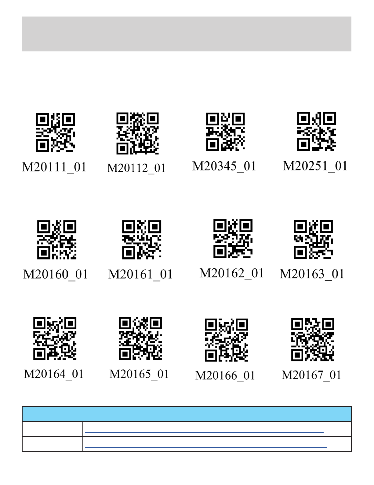
CR950/CR1100 Configuration Codes
Conguration changes will take effect immediately and be saved to memory
Reset and Reboot
Note: When a Factory Reset is performed, a Reboot will be necessary.
Factory Reset Reboot Reader
1A
Baud Rate
RS232 Interface
2A
1200 Baud Rate
Reset to RS232
1B
Factory Defaults
RS232 Interface
2B
2400 Baud Rate
1C 1D
2C 2D
RS232 Interface
4800 Baud Rate
Enable RS232
Serial Mode
(Default)
RS232 Interface
9600 Baud Rate
RS232 Interface
3A
19200 Baud Rate
Additional conguration codes can be found in the conguration guides as follows:
CR950 https://www.automationdirect.com/pn/doc/manual/CR950-K301-C298
CR1100 https://www.automationdirect.com/pn/doc/manual/CR1100-K201-C298
Code Handheld Scanner Supplemental Programming Manual - 2
RS232 Interface
3B
38400 Baud Rate
3C 3D
RS232 Interface
57600 Baud Rate
RS232 Interface
115200 Baud Rate
(Default)
Page 3
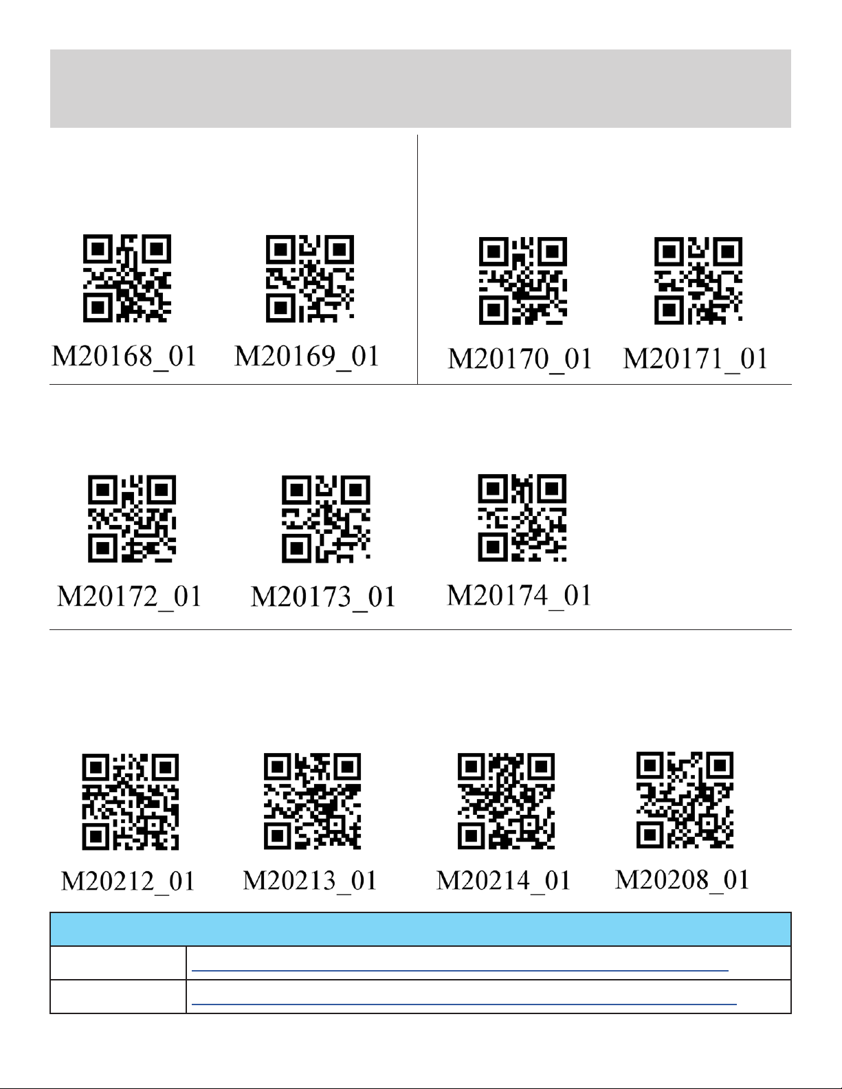
CR950/CR1100 Configuration Codes (continued)
Conguration changes will take effect immediately and be saved to memory
Data Bits
RS232 Interface
4A
7 Data Bits
Parity
RS232 Interface
5A
Even Parity
RS232 Interface
4B
8 Data Bits
(Default)
RS232 Interface
5B
No Parity
Stop Bit
RS232 Interface
4C
1 Stop Bit
(Default)
RS232 Interface
5C
Odd Parity
RS232 Interface
4D
2 Stop Bit
Sufx
Sufx Carriage
6A
Return
(RS232 Mode Only)
Additional conguration codes can be found in the conguration guides as follows:
CR950 https://www.automationdirect.com/pn/doc/manual/CR950-K301-C298
CR1100 https://www.automationdirect.com/pn/doc/manual/CR1100-K201-C298
Code Handheld Scanner Supplemental Programming Manual - 3
Sufx Carriage Return
6B
Line Feed
(RS232 Mode Only)
(Default)
Sufx Line Feed
6C
(RS232 Mode Only)
Erase Sufx Data
6C
Page 4

CR6022 Series Configuration Codes
Conguration changes will take effect immediately and be saved to memory
Reset and Reboot
Reset to RS232
7A
Factory Defaults
Baud Rate
RS232 Interface
8A
1200 Baud Rate
Reset to USB
7B
Factory Defaults
RS232 Interface
8B
2400 Baud Rate
Reboot Reader
7C
RS232 Interface
8C
4800 Baud Rate
Note: When a
Factory Reset is
performed, a Reboot
will be necessary.
RS232 Interface
8D
9600 Baud Rate
RS232 Interface
9A
19200 Baud Rate
Additional conguration codes can be found in the conguration guide as follows:
CR6022 https://www.automationdirect.com/pn/doc/manual/CR6022-C500-C298
Code Handheld Scanner Supplemental Programming Manual - 4
RS232 Interface
9B
38400 Baud Rate
RS232 Interface
9C
57600 Baud Rate
RS232 Interface
9D
115200 Baud Rate
(Default)
Page 5

CR6022 Series Configuration Codes (continued)
Conguration changes will take effect immediately and be saved to memory
Data Bits
RS232 Interface
10A
7 Data Bits
Parity
RS232 Interface
11A
Even Parity
RS232 Interface
10B
8 Data Bits
(Default)
11B
RS232 Interface
Odd Parity
Stop Bit
RS232 Interface
10C
11C
Stop Bit 1
(Default)
RS232 Interface
No Parity
(Default)
RS232 Interface
10D
Stop Bit 2
Sufx
Sufx Carriage Return
12A
(RS232 Mode Only)
Additional conguration codes can be found in the conguration guide as follows:
CR6022 https://www.automationdirect.com/pn/doc/manual/CR6022-C500-C298
12B
Code Handheld Scanner Supplemental Programming Manual - 5
Sufx Carriage Return
Line Feed
(RS232 Mode Only)
Sufx Line Feed
12C
(RS232 Mode Only)
Erase Sufx Data
12D
(Default)
Page 6
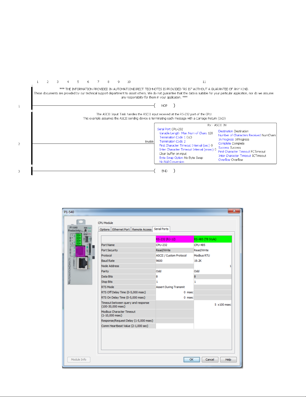
Productivity PLC Example
The Productivity PLC ASCII Input Task handles the ASCII input received at the RS-232 port of the
CPU. This example assumes the ASCII sending device is terminating each message with a carriage
return (0xD)
The Serial Port needs to be set up. This example assumes Baud Rate = 9600, Parity = Odd,
Data Bits = 8, and Stop Bits = 1, but any conguration can work.
Code Handheld Scanner Supplemental Programming Manual - 6
Page 7

CLICK Example
The CLICK programming example is a three-step process that (1) receives the data from the scanner
and (2) places that data in holding register before (3) moving it to the nal register.
Main Program
The EnableReceive bit is triggered automatically with the First Scan and during the
"CycleReceiveEnable" subroutine. Therefore, after each successful read of the incoming ASCII string,
the EnableReceive bit will be reset and set again, allowing the RECEIVE instruction to be re-enabled
for the next incoming string.
In order to keep shorter strings from inheriting residual characters from previous strings of a longer
length, TXT130 through TXT257 (128 bytes) are temporary holding registers for the incoming ASCII
string and will be cleared once the data has been moved from TXT130 (128 bytes) to TXT1 (128
bytes.)
Code Handheld Scanner Supplemental Programming Manual - 7
Page 8

CLICK Example (continued)
Subroutine Programs
"FirstScan" – This subroutine is called upon rst scan (SC2). It initializes (clears) registers and SETS
the “EnableReceive” bit that enables the RECEIVE instruction. The RECEIVE instruction is located in
the main program.
Code Handheld Scanner Supplemental Programming Manual - 8
Page 9

CLICK Example (continued)
"ASCII_RxSuccess" – This subroutine is called after success of the RECEIVE instruction below.
Move ASCII data from the 128 bytes of temporary registers (TXT130-257) to TXT1-128.
Fill the 128 bytes of temporary registers (TXT130-257) with the null from TXT129.
The RECEIVE instruction needs to see a transition from OFF to ON in order to be re-enabled. So
RESET the "Success" bit and the "EnableReceive" bit, and SET the "Cycle" bit that will trigger a
subroutine to SET the "EnableReceive" bit once again.
Move the "Port2 Data Length" from the system data register, SD50, to user register "CharReceived."
Code Handheld Scanner Supplemental Programming Manual - 9
Page 10

CLICK Example (continued)
"CycleReceiveEnable" – After the "ASCII_RxSuccess" subroutine, the "EnableReceive" bit is
RESET. The "CycleReceiveEnable" subroutine SETS the bit once again, allowing the OFF to ON
transition the RECEIVE instruction requires to execute again.
"ErrorHandling" – This subroutine is placed here for the user to write code to handle any errors
encountered from the RECEIVE instruction (First Character Timeout, Character Interval Timeout, and
Overow.)
Below are the bits that are used in the code shown above:
Code Handheld Scanner Supplemental Programming Manual - 10
Page 11
CLICK Example (continued)
The Com Port needs to be set up. This example assumes Baud Rate = 9600, Parity = Odd,
Data Bits = 8, and Stop Bits = 1, but any conguration can work.
Code Handheld Scanner Supplemental Programming Manual - 11
Page 12

BRX Example
Main Program
The ASCII Input program (Pgm_ASCII_Input) handles the internal serial input. On rst scan RUN this
program.
Pgm_ ASCII_Input
Upon initially running the program, CLEAR the internal serial port. This will delete any data in the Input
Queue data storage, as well as reset the .InQueue value.
IF the character count at the internal Serial buffer (IntSerial.InQueue) is greater than zero, THEN
execute the STREAMIN Instruction and populate SL0 (sInputString) element
This stage serves two purposes:
1) It allows the user to write any code required for parsing the input string and placing the parsed
content to other memory elements
2) Once the stage is complete, a jump is executed back to stage 1, allowing for a new evaluation of
the IntSerial.InQueue value.
Code Handheld Scanner Supplemental Programming Manual - 12
Continued...
Page 13

BRX Example (continued)
This stage is placed here for the user to write any required code for handling any errors encountered
during the execution of this program.
The Serial Port needs to be set up. This example assumes Baud Rate = 9600, Parity = Odd,
Data Bits = 8, and Stop Bits = 1, but any conguration can work.
Code Handheld Scanner Supplemental Programming Manual - 13
Page 14

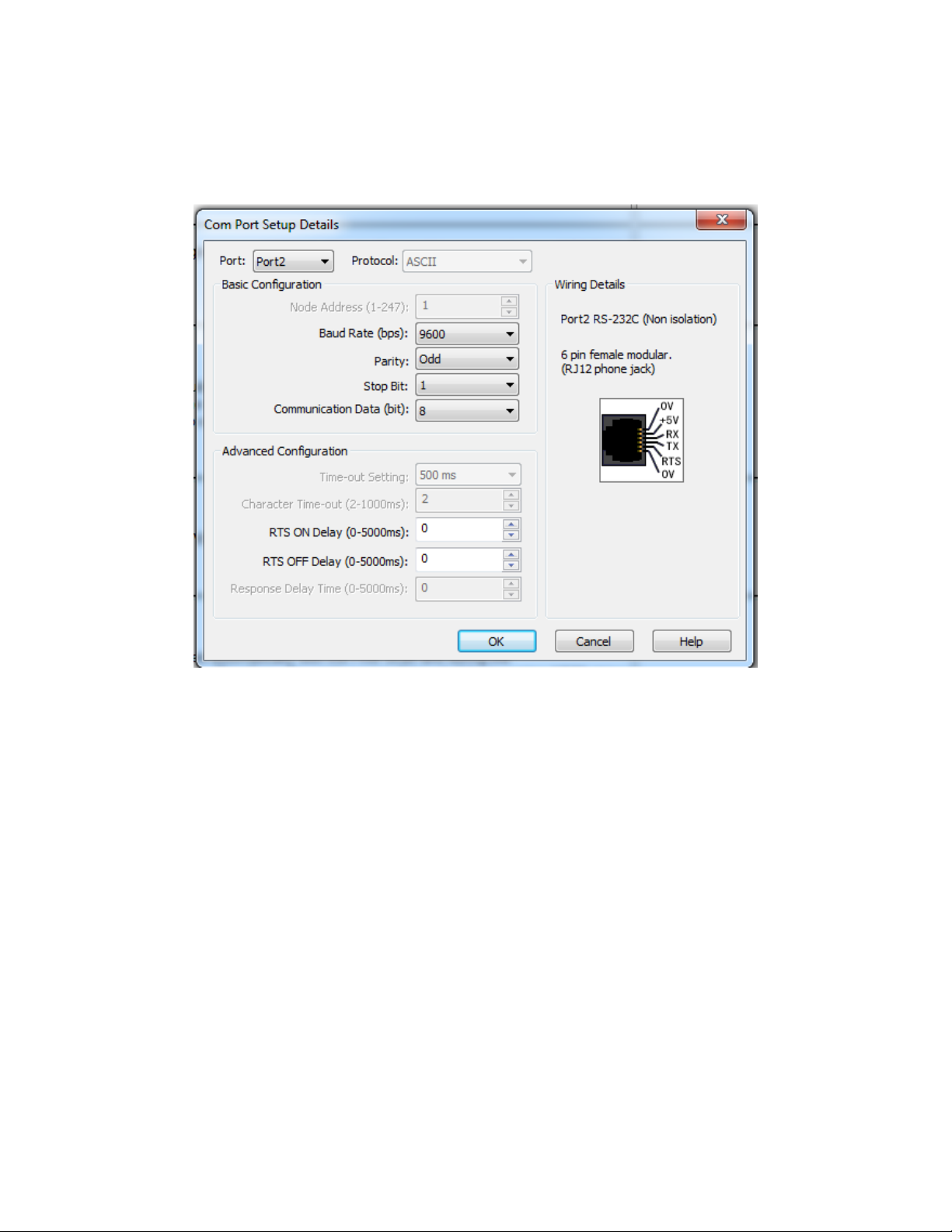
DirectLogic Example
The ASCII input (AIN) instruction is used to receive the ASCII data through port 2 of the DL06 PLC.
This example is using the termination code 0xD. Ensure that the barcode scanner is set up to send
the termination code.
AIN instruction setup
Secondary COM port setup
Code Handheld Scanner Supplemental Programming Manual - 14
Page 15

DirectLogic Example (continued)
Components used:
• PLC: D0-06AR (using serial port 2)
• ZL-CMA15L (connected to port 2 of the D0-06AR)
• ZL-RTB-RJ12 (the RJ12 cable from the barcode reader connects here and is then wired to the ZL-
CMA15L)
Code Handheld Scanner Supplemental Programming Manual - 15
Page 16

C-more HMI Examples for CR950/CR1100 Series
Compatibility
Scanner C-more EA7* C-more EA9
CR950-K301-C298
CR1100-K201-C298
* Please note that the C-more EA7 is no longer in active production.
Yes Yes
Yes Yes
There are two ways to get the CR950/CR1100 to communicate with the C-more HMI
1. Enable Alternate Operating System (EA9 only) 2. Declare Enumeration (EA7 or EA9)
Alternate Operating System ON. Alternate Operating system OFF.
Declare Enumeration when addressed.
In all of the above examples, depending on the application, it may become necessary to add
an Enter to the sufx by scanning the following:
Sufx Enter (USB keyboard only)
Erase Sufx Data
Additional conguration codes can be found in the conguration guides as follows:
CR950 https://www.automationdirect.com/pn/doc/manual/CR950-K301-C298
CR1100 https://www.automationdirect.com/pn/doc/manual/CR1100-K201-C298
Code Handheld Scanner Supplemental Programming Manual - 16
Page 17

C-more HMI Examples for CR6022 Series
Compatibility
Scanner C-more EA7* C-more EA9
CR6022-C500-C298
* Please note that the C-more EA7 is no longer in active production.
Yes No
There are three ways to get the CR6022 to communicate with the EA7 HMI
1. Alternate Operating System ON.
Alternate Operating System OFF.
2. Declare Enumeration after the Get
Report descriptor.
3. Declare Enumeration after Set
Conguration.
In all of the above examples, depending on the application, it may become necessary to add
an Enter to the sufx by scanning the following:
Sufx Enter (USB keyboard only)
Erase Sufx Data (Default)
Additional conguration codes can be found in the conguration guide as follows:
CR6022 https://www.automationdirect.com/pn/doc/manual/CR6022-C500-C298
Code Handheld Scanner Supplemental Programming Manual - 17
 Loading...