

Page 1
RHINO Installation Instructions for PSS0524-100 Power Supply
READ INSTRUCTIONS BEFORE INSTALLING OR OPERATING THIS DEVICE. KEEP FOR FUTURE REFERENCE.
1. Safety instructions
• To ensure sufficient convection cooling, always maintain a safety distance of M 20 mm (0.79 in) from all
ventilated surfaces while the device is in operation.
• The device is not recommended to be placed on low thermal conductive surface, for example, plastics.
• Note that the enclosure of the device can become very hot depending on the ambient temperature and load
of the power supply. Do not touch the device while it is in operation or immediately after power is turned OFF.
Risk of burning.
• Do not touch the terminals while power is being supplied. Risk of electric shock.
• Prevent any foreign metal, particles or conductors from entering the device through the openings during installation. It can cause electric shock, safety hazard, fire, and/or product failure.
• Warning: When connecting the device, secure GND connection before connecting L and N. When
disconnecting the device, remove the L and N connections before removing the GND connection.
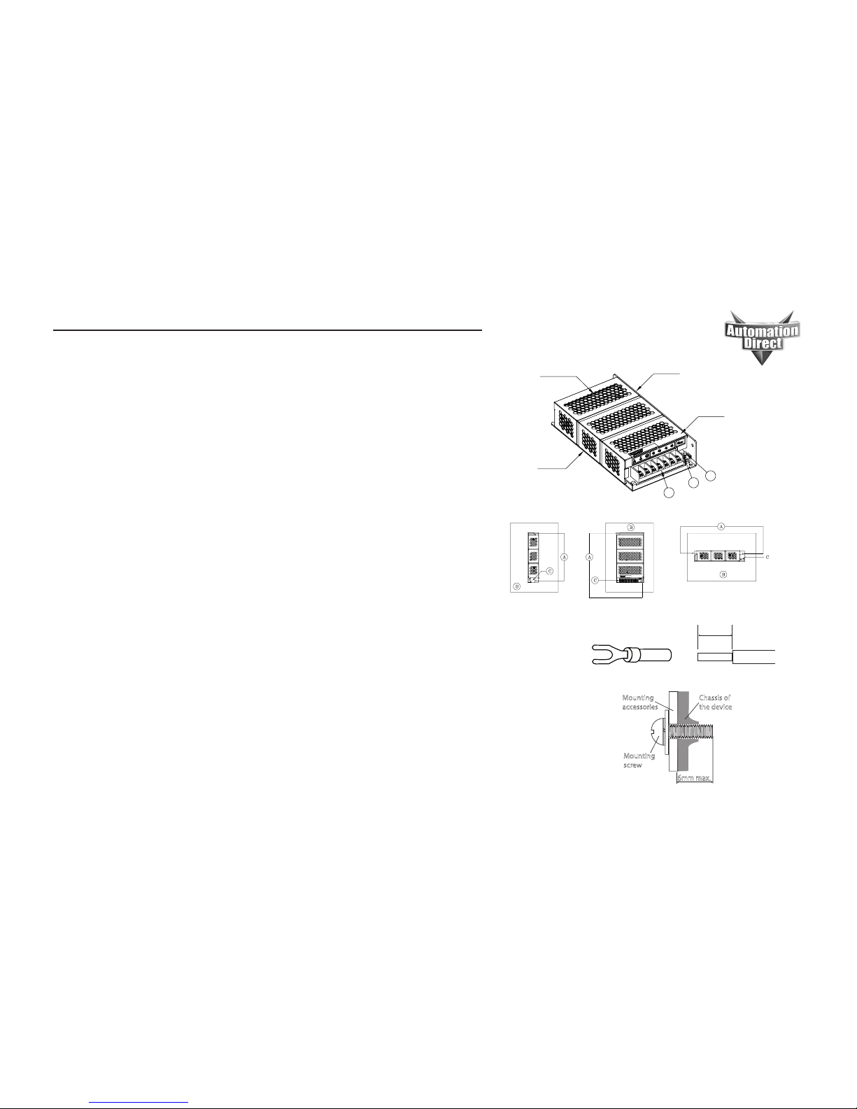
2. Device description (Fig. 1)
(1) Input & Output terminal block connector (V1: 24VDC, V2: 5VDC)
(2) DC voltage adjustment potentiometer for V1: 24VDC
(3) DC OK indicatorLED (green)
3. Connection (Fig. 1)
The terminal block connector allows easy and fast wiring.
4. Mounting (Fig. 2)
A. Mounting holes for power supply assembly onto the mounting surface. Power supply shall be mounted on
minimum 2 mounting holes using M3 x 0.5 screw minimum 5 mm (0.19 in) length.
B. This surface belongs to customer’s system or panel where the power supply is mounted.
C. Connector:
Use flexible (stranded wire) or solid wire 22–12 AWG. The torque at the connector shall not
exceed 1.3 Nm (11.3 in-lb). The insulation stripping length should not exceed 0.28 in or 7 mm.
Fork terminal recommended for stranded wire. Refer to figure 3.
5. Installation of Mounting Accessories (Fig. 4)
• Only use M3 screw m 6 mm through the base mounting holes. This is to keep a safety distance between the
screw and internal compontents.
• Refer to Figure 4: Recommended mounting tightening torque: 0.4 to 0.8 Nm (3.5 to 7 in-lb).
FOR TECHNICAL ASSISTANCE CALL 770-844-4200
1
2
3
Top surface
Side surface
Ventilated surface
Base surface
Figure 1 - Device Descriptions
Figure 2 - Mounting
7mm
[0.28in]
Figure 3 - Wire Type
AutomationDirect
P/N V70GK004003 (22-18AWG)
V70GK004008 (16-14AWG)
V70GK004003 (12AWG)
or equivalent
Mounting
accessories
Chassis of
the device
Mounting
screw
6mm max.
Figure 4 - Mounting Screw
Side Mounting (Vertical) Base Mounting (Vertical) Side Mounting (Horizontal)
Page 2
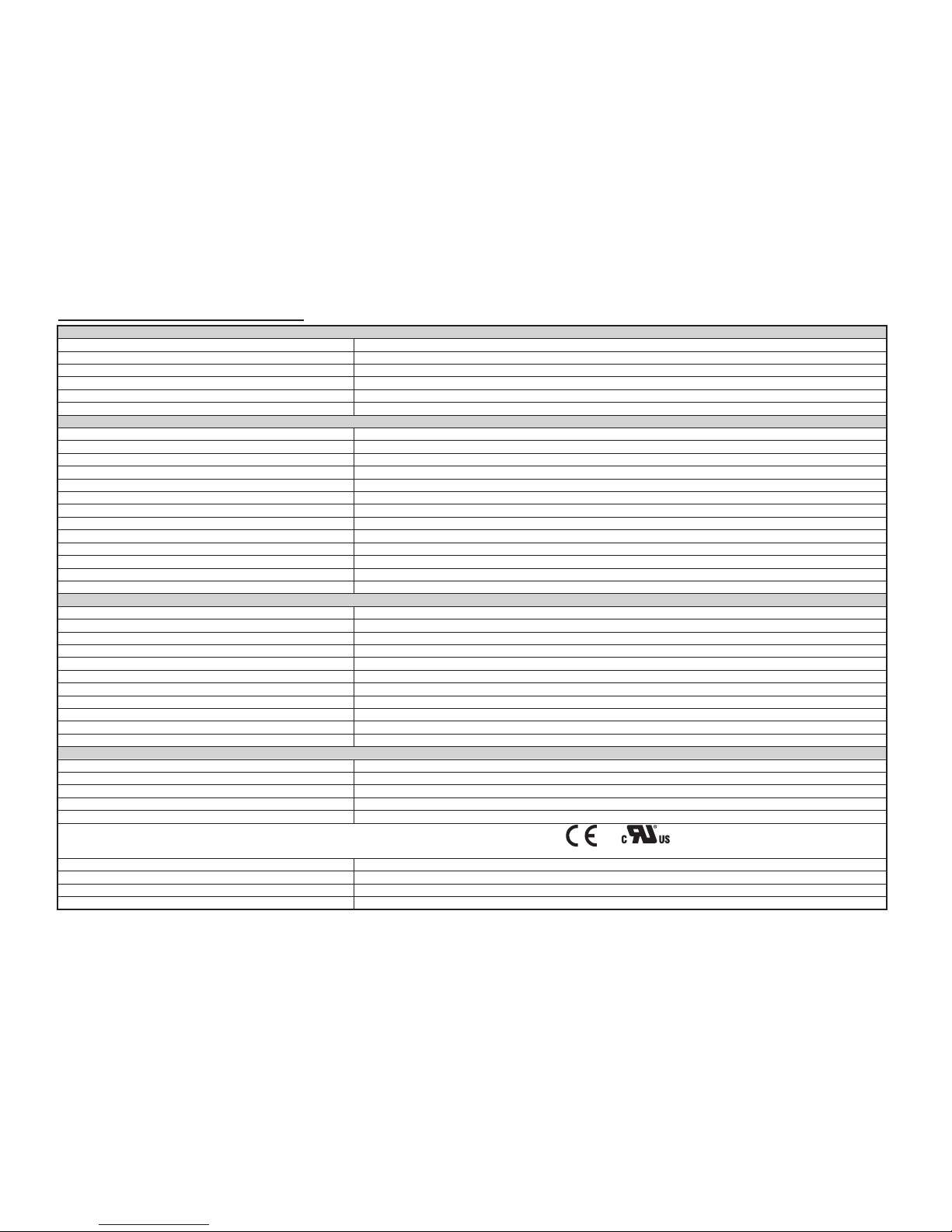
Technical Data For PSS0524-100
All parameters are specified at 25°C (77°F)
* Operating to 70 °C (158°F) possible with a linear derating to half power from 50°C to 70°C (122°F to 158°F)
Input (AC)
Nominal input voltage 100-240 VAC / 125-250 VDC
Voltage range 85-264 VAC (DC input range 125-375 VDC)
Frequency 47-63 Hz (0 Hz @ DC input)
Nominal current 2.0A max. @ 115 VAC, 1.1A max. @ 230 VAC
Inrush current limitation. I2t (+25 °C) typ. < 50A @ 115 VAC, < 100A @ 230 VAC
Leakage current < 1 mA @ 240 VAC
Output (DC)
Nominal output voltage / adjustment range V1: 24 VDC / 22.8-26.4 VDC; V2: 5 VDC / fixed
Output Voltage Tolerance V1: +/- 2% (initial setpoint tolerance from factory); V2: fixed
Output power* 100W
Output current V1: 0.3-4.0 Amp; V2: 0.8-7.0 Amp (each output can work within the current range, but ensure that the total output power does not exceed 100W)
PARD (ripple and noise) (20MHz) V1: <200mVpp; V2: <80mVpp (each measured with AC coupling mode, and in parallel with 0.1uF ceramic capacitor and 47uF electrolytic capacitor.)
Start-up time <1000ms@100% load and typical line input
Hold-up time > 15ms @ 115VAC, >80ms @ 230VAC with 100% load
Rise time V1: <30ms; V2: <20ms @100% load
Dynamic response (overshoot and undershoot O/P voltage) +/-5%@V1: 0-100% rated load and V2: 60%rated load and vice versa (Slew rate: 0.1A/uS)
Start-up with capacitive loads V1: 4000uF max
Efficiency > 84% @ 115 VAC & > 86% @ 230 VAC
Line regulation < 0.5% typical (@ 85-264VAC input)
Load regulation <1% typical (@85 to 264 VAC input, V1: 20-100% rated load and V2: 60% rated load and vice versa)
General Data
Type of housing Aluminum
Dimensions (L x W x H) 178 mm x 97 mm x 38 mm (7.0 in x 3.82 in x 1.50 in)
Weight 0.52 kg (1.15 lb)
MTBF > 700,000 hrs.
Connection method Screw connection
Noise Sound pressure level (SPL) < 40 dBA
Cooling Convection
Terminal input/output M3.5 x 7 Pins (Rated 300V/15A)
Wire size / torque 0.82-2.08 mm² (AWG 18-14) / 1.3 Nm (11.3 in-lb)
Shock test (non-operating) IEC60068-2-27, 30G (300m/S²) for a duration of 18ms 3 times per direction, 18 times in total
Vibration (non-operating) IEC60068-2-6, 10Hz to 150Hz @ 50m/S² (5G peak); 20 min per axis for all X, Y, Z direction
Safety / Environmental
EMC / Emissions FCC Title 47, Class B/EN55032;CISPR32, Class B
Immunity IEC61000-4-2; IEC61000-4-3; IEC61000-4-4; IEC61000-4-5; IEC61006-4-6; IEC61006-4-8; IEC61006-4-11; IEC61006-4-12
Voltage dips IEC61000-4-11 100% dip; 1 cycle (20ms); self recoverable
Galvanic isolation Input to Output : 3KVAC, Input to Ground : 1.5KVAC, Output to Ground : 0.5KVAC
Approvals UR/cUR recognized to UL60950-1 and CSA C22.2 No. 60950-1 (file no. E198298); CB test certificate and report to IEC60950-1, CE (EMC and Low Voltage directive)
E198298
RoHS Compliant Yes
Operating temperature -10 °C to +70 °C* (14°F to 158°F)
Storage temperature -25 °C to +85 °C (-13°F to 185°F)
Humidity < 95 % RH non-condensing
 Loading...