

Page 1

RHINO Installation Instructions for PSD24-240-L Power Supply
-25
-20
-15
-10-50510152025303540455055606570
Surrounding Air Temperature
-13-4514233241505968778695
104
113
122
131
140
149
158
READ INSTRUCTIONS BEFORE INSTALLING OR OPERATING THIS DEVICE. KEEP FOR FUTURE REFERENCE.
(2)
(3)
(11)
(1)
(4)
(5)
(6)
Figure 1
2
1
3
1
Figure 2 Figure 3
Normal mode OFF ON Closed
During Power Boost OFF ON Closed
Overload (V
Output short circuit Flashing OFF Open
Temperature shut down Flashing OFF Open
No input power OFF OFF Open
< 90%) Flashing OFF Open
out
Overload LED DC OK LED DC OK Contact
Figure 4
7mm
[0.28in]
1
Figure 5
TN-S
L N PE
TN-C
L
N
PE
L N PE
L
PEN
++
TT
L N PE
Figure 6
110
100
90
80
70
60
50
40
30
20
Percentage of Max Load (%)
10
0
Power Derating Curve for PSU
Surrounding Air Temperature
Vertical Mounting Horizontal Mounting
Figure 7
(8)
(10)
(9)
1. Safety instructions
• An easily accessible disconnecting device shall be provided to disconnect the unit from the mains supply for
servicing.
• Switch main power off before connecting or disconnecting the device. Risk of explosion!
(7)
• If the unit is used in a manner not specified by the manufacturer, the protection provided by the equipment may
be impaired.
• To guarantee sufficient convection cooling, please refer to the following instructions to ensure sufficient clearance
around the device.
Vertical Mounting: 40 mm [1.57 in] above and 20 mm [0.79 in] below the device as well as a lateral distance of
5 mm [0.20 in] to other units. In case the adjacent device is a heat source, the lateral distance will be 15 mm [0.59 in].
Horizontal Mounting: 40 mm [1.57 in] above and below the device as well as a lateral distance of 20 mm [0.79 in] to
other units.
• The external enclosure where the unit will be installed shall meet the requirements for mechanical, electrical and
fire enclosure.
• Note that the enclosure of the device can become very hot depending on the ambient temperature and load of the
power supply. Risk of burns!
• The main power must be turned off before connecting or disconnecting wires to the terminals!
• Do not introduce any objects into the unit!
• Dangerous voltage present for at least 5 minutes after disconnecting all sources of power.
• The power supplies are built in units and must be installed in a cabinet or room (condensation free environment
2
3
and indoor location) that is relatively free of conductive contaminants.
• CAUTION: “For use in a controlled environment”.
2. Device description (Fig. 1)
(1) Input terminal block connector
(2) Output terminal block connector
(3) Alarm signal terminal block connector
(4) DC voltage adjustment potentiometer
(5) DC OK LED (green)
(7) LCD display
(8) Back key
(9) Forward key
(10) Mode key
(11) 35mm DIN rail mounting (DIN rail sold separately)
(6) Overload LED (red)
3. Mounting and dismounting (Fig. 2, Fig. 3)
The power supply unit can be mounted on 35 mm DIN rails in accordance with EN60715. For Vertical Mounting, the
device should be installed with input terminal block on the bottom. For Horizontal Mounting, the device should be
installed with input terminal block on the left side.
Each device is delivered ready to install.
1. Tilt the unit slightly upwards and put it onto the DIN rail. Snap on the DIN rail as shown in Fig. 2.
2. Push downwards until stopped.
3. Press against the bottom front side for locking.
4. Shake the unit slightly to ensure that it is secured.
5. To uninstall, pull or slide down the latch as shown in Fig. 3. Then, slide the PSU in the opposite direction, release
the latch and pull out the PSU from the rail.
4. Connection
The terminal block connectors allow easy and fast wiring.
You can use flexible (stranded wire) or solid cables with the following cross sections:
Table 1
Refer to Fig. 1:
Standard / Solid Torque
(mm²) (AWG) (Nm) (lb in)
(1) 0.82-8.4 18-8 0.91 8.1
(2) 1.3-3.3 16-12 0.61 5.4
2
(3) 0.52-1.3 (solid cable) 20-16 (solid cable) - -
To secure reliable and shock proof connections, the stripping length should be 7 mm [0.28 in] (see Fig. 5 (1)). Please
ensure that wires are fully inserted into the connecting terminals as shown in Fig. 5 (2). All wire strands must be
fully inserted into the terminals with the screws securely fastened in order to ensure safety and maximum contact.
In accordance to EN 60950 / UL 60950, flexible wires require ferrules.
Use appropriate copper wire that is designed to sustain operating temperature of :
1. At least 60°C / 75°C (140°F / 167°F) for USA.
2. At least 90°C (194°F) for Canada and IEC/EN61010-1, IEC/EN61010-2-201.
4.1. Input connection (Fig. 1, Fig. 6)
L N PE
iT
L
N
+
L
N
+
For AC input connections, use L, N and PE connections on the input terminal connector (see Fig. 1 (1)) to establish
the 100-240 VAC connection. Fig. 6 shows the connection to the various network types.
For DC input connections, connect L pin to + from DC source and connect N pin to − from DC source.
The unit is protected with internal fuse (not replaceable) at L pin and it has been tested and approved on 20A (UL)
and 16A (IEC) branch circuits without additional protection device. An external protection device is only required
if the supplying branch has an ampacity greater than above. Thus, if an external protective device is necessary, or,
utilized, a minimum value of 6A B- or 4A C- characteristic breaker should be used.
The internal fuse must not be replaced by the user.
4.2. Output Connection (Fig. 1 (2))
Use the “+” and “-” screw connections to establish the 24 VDC connection. The output provides 24 VDC. The output
voltage can be adjusted from 24 to 28 VDC on the potentiometer. The green LED DC OK displays correct function of
the output (Fig. 1 (5)). The device has a short circuit and overload protection and an overvoltage protection limited
to 35 VDC.
4.3. Output characteristic curve
The device functions normal under operating line and load conditions. In the event of an over load (IO > 150%) the
output voltage will start to droop and bounce until over load has been removed.
4.4. Indicators and relay contacts (Fig. 4)
4.5. Thermal behavior (Fig. 7)
(oC)
(oF)
If the output capacity is beyond what is recommended in Fig. 7, the device will run into thermal protection by
switching off i.e. device will go in bouncing mode and will recover when ambient temperature is lowered or load is
reduced as far as necessary to keep device in working condition.
FOR TECHNICAL ASSISTANCE CALL 770-844-4200
Page 2
Technical Data For PSD24-240-L
■
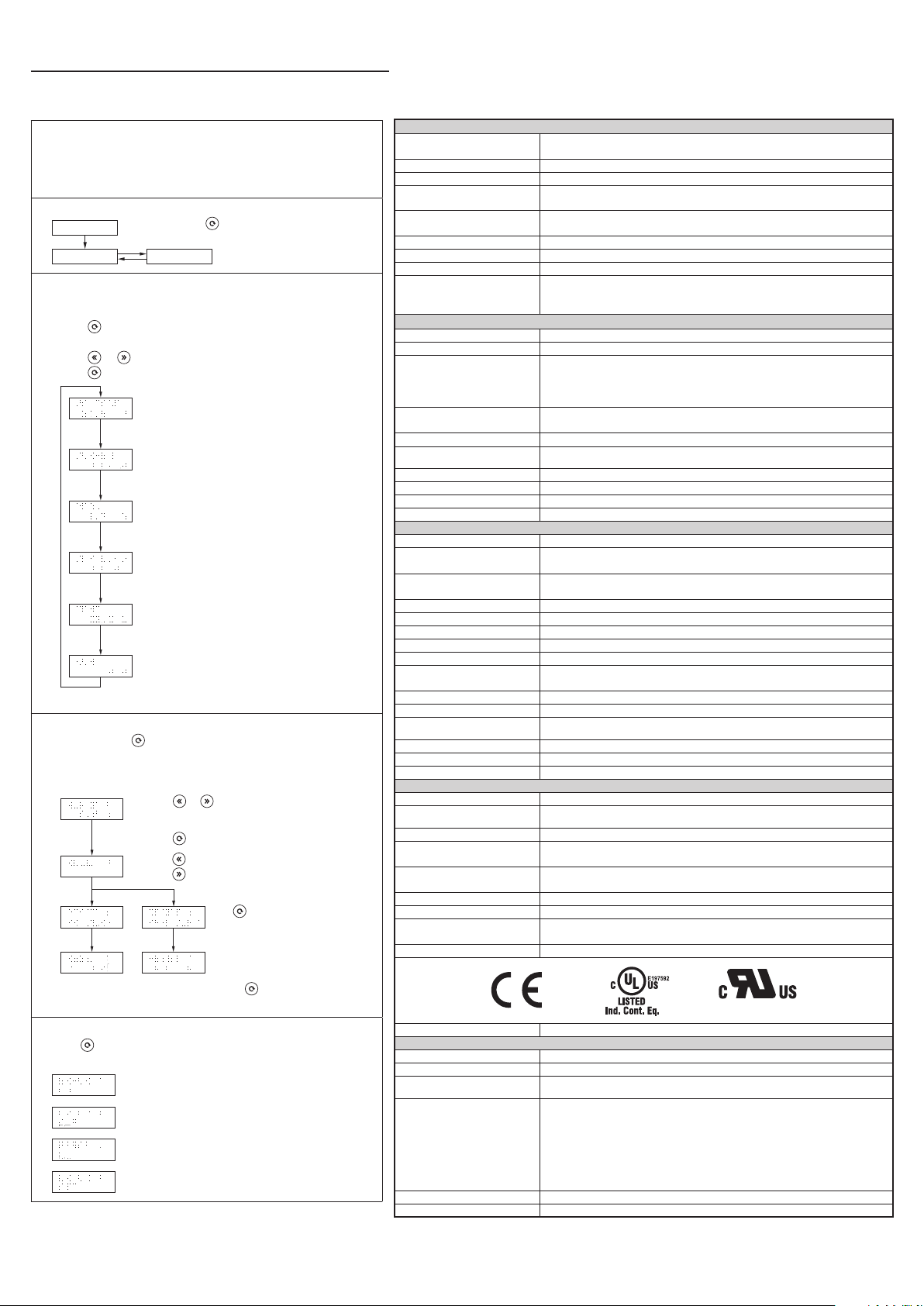
What is the “Lifetime Expectancy Function”?
The lifetime expectancy function indicates an approximate period
of life left for the power supply unit, based on deterioration of the
electrolytic capacitor. It does not predict failures caused by other
reasons.
■
Mode Change
Power ON
Display Mode Setting Mode
■
Display Mode
Press and hold (mode key) for 5 seconds or more to
change the mode.
By default, the power supply unit is set to auto display mode and will
show the status in the following sequence below.
• Press (mode key) to freeze the current indicated status on the
LCD display.
• Press or (back or forward key) to move between each status.
• Press (mode key) to return to auto display mode.
Output voltage
Values will show up to 2 decimal places (accuracy of output
voltage indication is ±2%).
Output current
Values will show up to 2 decimal places (accuracy of output
current indication is ±5%).*
Peak hold current
Values will show up to 2 decimal places (accuracy of peak
hold current indication is ±5%).* The minimum signal width
required for hold current is 20 ms.
Lifetime expectancy
Values will show up to 1 decimal place. The lifetime
expectancy is calculated by the amount of deterioration of
the electrolytic capacitor according to the running hours and
inside ambient temperature.
Ambient temperature
This is ambient temperature inside the power supply unit.
Monitored readings will be displayed about 30 seconds after it
is turned on. Values will show up to 1 decimal place.
KWH
Values will show up to 1 decimal place. The KWH is calculated
based on the running hours and output power.
*If Io < 5%, accuracy is ±10%.
■
Setting Mode
• Press and hold (mode key) for 5 seconds or more to change from
“Display Mode” to “Setting Mode”.
• The power supply unit will show the items in the following sequence
below.
• Press or (back or forward key) to increase or
decrease the alarm setting.
Factory setting is 10.0 years and minimum setting is 0.5 years.
• Press (mode key) to go to “Reset”.
• Press (back key) to reset peak hold current.
• Press (forward key) to reset KWH.
Press (mode key) to confirm and clear
peak hold current or KWH value.
Input (AC)
Nominal input voltage / frequency
Voltage range 85-276 VAC (DC input range 88-375 VDC)
Frequency 47-63Hz
Nominal current
Inrush current limitation
(+25°C, cold start)
Mains buffering at nominal load (typ.) 27 ms typ. @ 120 VAC, 28 ms typ. @ 230 VAC
Turn-on time < 650 ms @ 120 VAC, > 340 ms @ 230 VAC
Internal fuse T 6.3 A / 500 VAC or 400 VDC min.
Leakage current
TN/TT-system / IT-system: < 0.29 mA / 0.82 mA @ 110 VAC, 50Hz
TN/TT-system / IT-system: < 0.38 mA / 1.02 mA @ 132 VAC, 50Hz
TN/TT-system / IT-system: < 0.74 mA / 2.25 mA @ 264 VAC, 50Hz
100-240 VAC / 50-60Hz; or
110-300 VDC (for ITE only)
< 2.65 A @ 100 VAC, < 1.22 A @ 230 VAC
< 2.37 A @ 110 VDC, < 0.85 A @ 300 VDC
6 A typ. @ 120 VAC, 7 A typ. @ 230 VAC
Output (DC)
Nominal output voltage U
Adjustment range of the voltage 24-28 VDC
Nominal current
Derating
Startup with capacitive loads 10,000 µF typ.
Max. power dissipation idling / nominal
load approx.
Efficiency 92.6% typ. @ 120 VAC, 93.5% typ. @ 230 VAC
PARD (20MHz) at 100% load < 50 mVpp
Max. relay contact rating 30V (SELV) / 1 A resistive load
Parallel operation PSB60-REM20S / PSB60-REM40S
N
> 60°C [140°F] (2.5% / °C) in Vertical
> 50°C [122°F] (2.5% / °C) in Horizontal
General Data
Type of housing Aluminum
Signals
MTBF
Dimensions (L x W x H) 124 mm x 60 mm x 139 mm [4.88 in x 2.36 in x 5.47 in]
Weight 1.02 kg [2.25 lb]
Connection method Screw connection
Wire size / torque See Table 1
Stripping length 7 mm [0.28 in]
Operating temperature
(surrounding air temperature)
Storage temperature -40°C to +85°C [-40°F to 185°F]
Humidity at +25°C, no condensation 5 to 95% RH
Vibration (non-operating)
Shock (non-operating, in all directions) 30G (300m/S²) in all directions according to IEC60068-2-27
Pollution degree 2
Altitude (operating) 5000m
10 to 500Hz @ 30m/S² (3G peak); displacement of 0.35mm; 60 min. per axis for all X, Y, Z directions
> 1,268,000 hrs. as per Telcordia SR-332
(I/P: 100 VAC; O/P: 24V, 10 A; Ta: 25°C)
-25°C to +70°C [-13°F to 158°F] (Refer to Fig. 7)
Certification and Standards
Electrical equipment of machines IEC60204-1 (over voltage category III)
Electronic equipment for use in electrical
power installations
Safety entry low voltage PELV (EN 60204-1), SELV (EN 60950-1)
Electrical safety (of information
technology equipment)
Industrial control equipment
CE In conformance with EMC directive 2014/30/EU and low voltage directive 2014/35/EU
Component power supply for general use EN61204-3
Immunity
Emission EN55032, EN55011, EN61000-3-2 Class A, EN61000-3-3, EN61000-6-3
UL/C-UL recognized to UL60950-1 and CSA C22.2 No. 60950-1 (File No. E198298),
CB scheme to IEC 60950-1, IEC 61010-1, IEC 61010-2-201
UL/C-UL listed to UL508 and CSA C22.2 No. 107.1-01 (File No. E197592),
CSA to CSA C22.2 No. 107.1-01 (File No. 249074)
(EN61000-4-2, 3, 4, 5, 6, 8, 11, 12)
24 VDC
10 A (Vout = 24 VDC)
8.57 A (Vout = 28 VDC)
15 A (for 5 s, Vout = 24 VDC)
13.5 A (for 5 s, Vout = 28 VDC)
6.1W / 16.7W
Green LED DC OK
Red LED Overload
in acc. with IEC60068-2-6
IEC/EN 62477-1 / IEC62103
EN 55024, EN 61000-6-2
Note: To return to auto display mode, press and hold (mode key) for 5 seconds or
more.
■
Failure Mode Display
Press (mode key) to clear error messages and return to auto display
mode.
When overvoltage protection occurs (Auto-recovery)
When overload/overcurrent protection occurs (Auto-recovery)
When short circuit protection occurs (Auto-recovery)
When over temperature protection occurs (Auto-recovery)
Rev. 00, 07/2020
E198298
RoHS Compliant Yes
Safety and Protection
Transient surge voltage protection VARISTOR
Current limitation at short-circuits approx. Isurge = 150 % of Pomax typically (continuous current)
Surge voltage protection against internal
surge voltages
Isolation voltage:
Input / Output
Input / PE
Input / DC OK*
Output / PE
Output / DC OK
DC OK / PE
Protection degree IP20
Safety class Class I with GND connection
*Recommend connecting DC OK pins to output pins.
Yes
3.00 kVAC
2.00 kVAC
3.00 kVAC
1.50 kVAC
0.50 kVAC
1.50 kVAC
 Loading...