

Automation Direct ProSense VFS50-5-1001, ProSense VFS75-26-1001, ProSense VFS50-10-1001 Operating Instructions Manual
Page 1

Operating instructions
Vortex flow meter
VFS50-5-1001
VFS50-10-1001
VFS75-26-1001
80286262 / 00 06 / 2019
by Automationdirect.com
Page 2

Contents
1 Preliminary note ...................................................................................................2
1.1 Symbols used ................................................................................................2
1.2 Warning signs used .......................................................................................3
2 Safety instructions ...............................................................................................3
3 Functions and features ........................................................................................4
4 Function ...............................................................................................................4
4.1 Switching output ............................................................................................5
4.2 Frequency output ...........................................................................................6
5 Installation............................................................................................................6
6 Electrical connection ............................................................................................8
7 Operating and display elements ..........................................................................9
8 Menu ..................................................................................................................10
8.1 Main menu ...................................................................................................10
8.1.1 Explanation main menu ...................................................................... 11
8.2 Extended functions – basic settings ............................................................12
8.2.1 Explanation basic settings (CFG) .......................................................13
8.3 Extended functions – min / max memory – display .....................................14
8.3.1 Explanation min/max memory (MEM) ................................................15
8.3.2 Explanation display function (DIS) ....................................................15
9 Parameter setting ..............................................................................................16
9.1 Parameter setting in general .......................................................................16
10 Troubleshooting ...............................................................................................16
11 Factory setting .................................................................................................17
1 Preliminary note
1.1 Symbols used
► Instructions
> Reaction, result
[…] Designation of pushbuttons, buttons or indications
→ Cross-reference
2
Page 3

Important note
Non-compliance can result in malfunction or interference.
Information
Supplementary note.
1.2 Warning signs used
CAUTION
Warning of personal injury.
Slight reversible injuries may result.
2 Safety instructions
• The device described is a subcomponent for integration into a system.
- The manufacturer is responsible for the safety of the system.
- The system manufacturer undertakes to perform a risk assessment and to
create a documentation in accordance with legal and normative requirements
to be provided to the operator and user of the system. This documentation
must contain all necessary information and safety instructions for the operator,
the user and, if applicable, for any service personnel authorised by the manufacturer of the system.
• Read this document before setting up the product and keep it during the entire
service life.
• The product must be suitable for the corresponding applications and environmental conditions without any restrictions.
• Only use the product for its intended purpose (→ Functions and features).
• Only use the product for permissible media (→ Technical data).
• If the operating instructions or the technical data are not adhered to, personal
injury and/or damage to property may occur.
• The manufacturer assumes no liability or warranty for any consequences
caused by tampering with the product or incorrect use by the operator.
• Installation, electrical connection, set-up, operation and maintenance of the unit
must be carried out by qualified personnel authorised by the machine operator.
• Protect units and cables against damage.
3
Page 4

CAUTION
For medium temperatures above 50 °C (122 °F) some parts of the housing can
heat up to over 65 °C (149 °F). Risk of burns.
► In this case do not touch the unit.
► Protect the housing against contact with flammable substances and uninten-
tional contact.
► Do not press the pushbuttons manually; instead use another object (e.g.
ballpoint pen).
3 Functions and features
The unit monitors water-based fluids (water, deionized water, cooling water).
It detects the two process categories volumetric flow rate and medium tempera-
ture.
Pressure Equipment Directive (PED):
The units comply with the Pressure Equipment Directive and are designed
and manufactured for group 2 fluids in accordance with the sound engineering practice.
4 Function
• The unit detects the volumetric flow rate based on the Vortex measuring
principle.
• The unit displays the current flow and temperature. It generates 2 output
signals according to the parameter setting:
OUT1: 2 selection options
- switching signal for volumetric flow rate limit value
- frequency signal for volumetric flow rate
OUT2: 4 selection options
- switching signal for volumetric flow rate limit value
- switching signal for temperature limit value
- frequency signal for volumetric flow rate
- frequency signal for temperature
4
Page 5
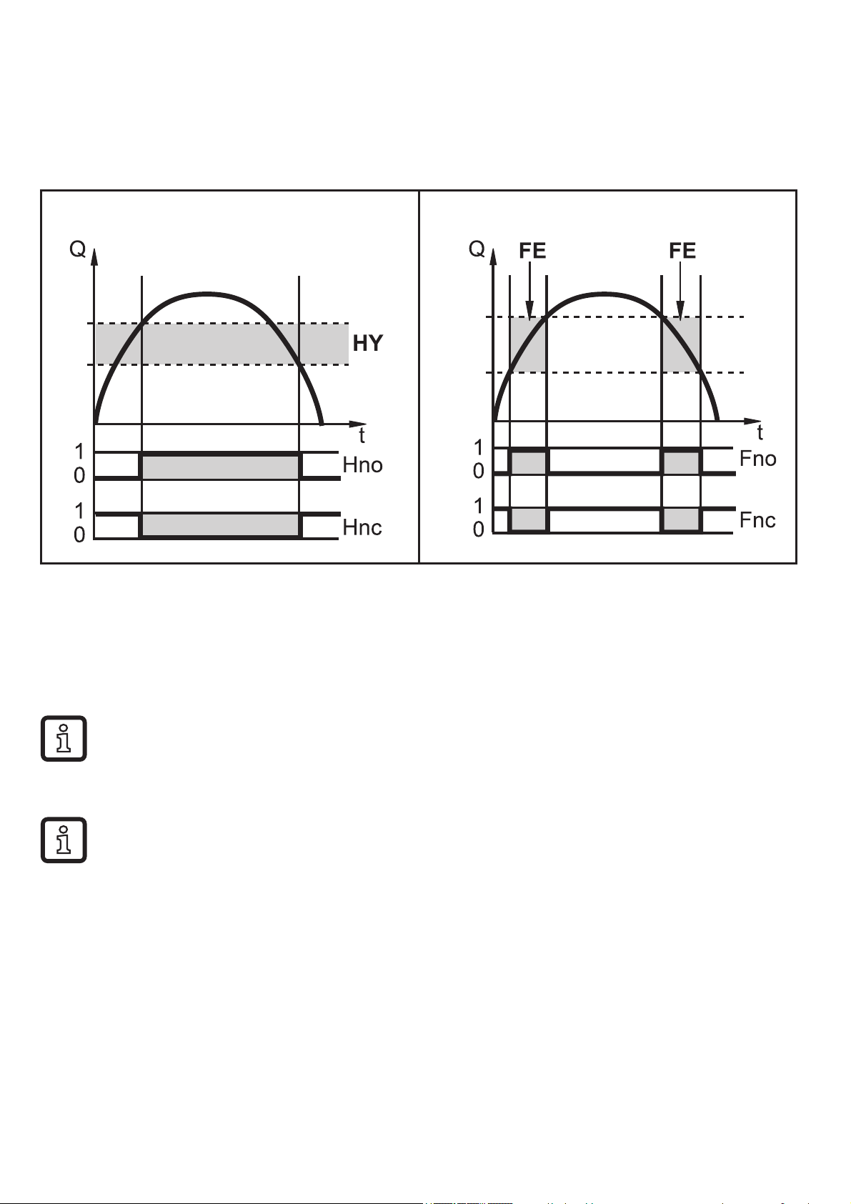
4.1 Switching output
OUTx changes its switching status if it is above or below the set switching limits
(flow or temperature). Hysteresis or window function can be selected. Example of
volumetric flow monitoring:
Hysteresis function Window function
SP
rP
SP = set point
rP = reset point
HY = hysteresis
Hno = hysteresis NO (normally open)
Hnc = hysteresis NC (normally closed)
When the hysteresis function is set, the set point [SPx] is defined first and
FH
FL
SP = upper limit
rP = lower limit
FE = window
Fno = window NO (normally open)
Fnc = window NC (normally closed)
then the reset point [rPx] which must have a lower value. If only the set
point is changed, the reset point remains constant.
When set to the window function, the upper limit [SPx] and the lower limit
[rPx] have a fixed hysteresis of 0.25 % of the final value of the measuring
range. This keeps the switching status of the output stable if the flow rate
varies slightly.
5
Page 6
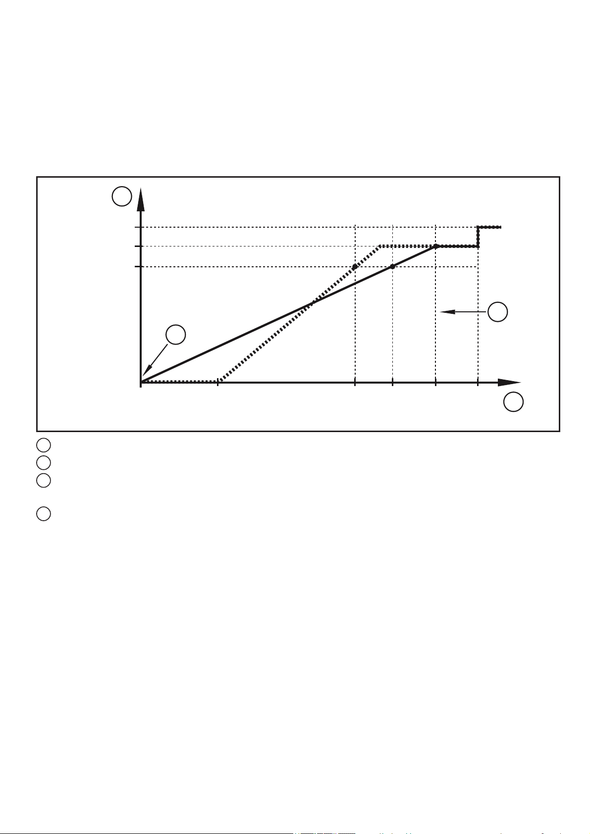
4.2 Frequency output
The unit provides a frequency signal that is proportional to the volumetric flow
quantity and the medium temperature.
Up to the limit value set under [FEPx] (for OUT2 = TEMP: between the limit values
set under [FSP2] and [FEP2]) the frequency signal is between 0 Hz and the fre-
x
quency value set under [FrP
1
130
%
120 %
100 %FrPx
].
OUT1
4
3
OUT2
0
%
OL
cr.OL
100
0
1
Frequency signal in Hz
2
Volumetric flow quantity or temperature
3
The device is in the error state (FOU = OFF) or the process value transmitted in an
FSP2
%
100
FEP2
FEP1
analogue way is below the display range or the current flow is 0.
4
The unit is in the error state (FOU = ON)
5 Installation
► Flow in the direction of the arrow. Observe the installation direction.
2
► Make sure that pipe and sensor have the same internal diameter.
► Avoid deposits, accumulated gas and air in the pipe system. Install the unit so
that the measuring pipe is always completely filled with medium.
► Install in front of or in a rising pipe.
► Recommended tightening torque: 30 Nm
► Avoid disturbances on the inlet and outlet side. To do so, provide for the
following inlet and outlet pipe lengths:
6
Page 7

1
2
F
DN = nominal width of the pipe
R = radius
Disturbance Inlet pipe length
(1)
Outlet pipe length
(2)
Non-ideal bend ≥ 5 x DN ≥ 1 x DN
Ideal bend
R1.8
x
DN
≥ 0.5 x DN
Multiple bends (2 x 90°) ≥ 15 x DN
Reduction of internal pipe diameter ≥ 15 x DN ≥ 15 x DN
Valve or pump ≥ 25 x DN
► Mount the unit in a way that no mechanical forces are exerted on the pipe. To
do so, use angle brackets if required.
- For direct installation fix the unit on the surface utilizing the four corner holes
on the underside of the unit. Mounting holes are 3.6 mm in diameter with a
57 mm x 16.5 mm on center pattern. Maximum insertion depth in the housing
is 5.5 mm. Use self-tapping M4 DIN 7500 screws. Center holes are not usable
due to risk of damaging sensor.
► Avoid the following installation positions:
- Directly in front of a falling pipe.
- In a falling pipe.
- At the highest point of the pipe system, when the pipe is open.
- Directly before the outlet of the pipe.
- On the suction side of a pump.
7
Page 8

6 Electrical connection
The unit must be connected by a qualified electrician.
The national and international regulations for the installation of electrical
equipment must be adhered to.
Voltage supply according to EN 50178, SELV, PELV.
► Disconnect power.
► Connect the unit as follows:
21
43
BK: black
BN: brown
BU: blue
WH: white
BN
1
WH
2
BK
4
BU
3
+
L
OUT2
OUT1
L
Colors to DIN EN 60947-5-2
Pin 1 L+
Pin 3 L-
Pin 4
(OUT1)
• Switching signal: limit values for volumetric flow
• Frequency signal for volumetric flow rate
• Switching signal: limit values for volumetric flow
Pin 2
(OUT2)
• Switching signal: limit values for temperature
• Frequency signal for volumetric flow rate
• Frequency signal for temperature
8
Page 9

7 Operating and display elements
1 2
5
1 and 2: switching status LEDs
3
4
• LED 1 = switching status OUT1 (lights when output 1 is switched)
• LED 2 = switching status OUT2 (lights when output 2 is switched)
3: TFT display
• Display of current process values (volumetric flow rate, temperature)
• Display of the parameters and parameter values
4: Buttons [▲] and [▼]
• Select parameters
• Change parameter values (hold button pressed)
• Change of the process value display in the normal operating mode (Run mode)
• Locking / unlocking (press buttons simultaneously > 10 seconds)
5: Button [●] = Enter
• Change from RUN mode to the main menu
• Change to setting mode
• Acknowledgement of the set parameter value
9
Page 10

8 Menu
8.1 Main menu
Process value display (RUN)
SP1
rP1
SP2
rP2
EF
FH1
FL1
FH2
FL2
FEP1
FrP1
FSP2
FEP2
FrP2
1
2
&)*0(0'ආ6
1: Output functions ou1 (→ 8.2.1)
2: Output functions ou2 (→ 8.2.1)
The parameters are only displayed when selected at ou1 / ou2.
10
Page 11

8.1.1 Explanation main menu
Switching output with hysteresis function
SP1 Set point 1 = upper limit value at which OUT1 switches.
rP1 Reset point 1 = lower limit value at which OUT1 switches off.
SP2 Set point 2 = upper limit value at which OUT2 switches.
rP2 Reset point 2 = lower limit value at which OUT2 switches off.
Switching output with window function
FH1 Set point 1 = upper limit value at which OUT1 switches.
FL1 Reset point 1 = lower limit value at which OUT1 switches.
FH2 Set point 2 = upper limit value at which OUT2 switches.
FL2 Reset point 2 = lower limit value at which OUT2 switches.
Frequency output
FEP1 Process value end point on OUT1.
FrP1 Frequency at process value end point (FEP1) on OUT1.
FSP2 Process value start point on OUT2 (only if SEL2 = TEMP).
FEP2 Process value end point on OUT2.
FrP2 Frequency at process value end point (FEP2) on OUT2.
Extended functions
EF Opening of the lower menu level.
11
Page 12

8.2 Extended functions – basic settings
Main menu
RUN
EF CFG
rES
ආQIR
CFG
MEM
'ආ6
- - - -
ou1 Hno Hnc Fno Fnc FRQ
ou2
dS1
dr1
dS2
dr2
uni
P-n
Hno Hnc Fno Fnc FRQ
0.0...60 s
0.0...60 s
0.0...60 s
0.0...60 s
gphgpm
PnP nPn
dAP
FOU1
FOU2
SEL2 FLOW TEMP
The parameters are only displayed when oux = Hno, Hnc, Fno, Fnc.
0.0...5.0 s
OFFOn OU
OFFOn OU
12
Page 13

rES Restoring the factory settings
Info Device information
CFG Submenu basic settings
MEM Submenu min/max memory
DIS Submenu display settings
8.2.1 Explanation basic settings (CFG)
ou1 Output function OUT1
• Flow: Hno, Hnc, Fno, Fnc, FRQ
ou2 Output function OUT2
• Flow: Hno, Hnc, Fno, Fnc, FRQ
• Temperature: Hno, Hnc, Fno, Fnc, FRQ
Hno Hysteresis function normally open
Hnc Hysteresis function normally closed
Fno Window function normally open
Fnc Window function normally closed
FRQ Frequency output
dS1 Switching delay on OUT1 in seconds
dr1 Switch-off delay on OUT1 in seconds
dS2 Switching delay on OUT2 in seconds
dr2 Switch-off delay on OUT2 in seconds
uni Standard unit of measurement for volumetric flow rate
P-n Output logic: pnp / npn
dAP Measured value damping in seconds (only for volumetric flow rate)
FOU1 Behavior of output OUT1 in case of an error
FOU2 Behavior of output OUT2 in case of an error
SEL2 Standard measured variable for evaluation by OUT2:
Volumetric flow rate or medium temperature
Only in case of ou
Hno, Hnc, Fno, Fnc
x
=
13
Page 14

8.3 Extended functions – min / max memory – display
Main Menu
rES
ආQIR
CFG
MEM
'ආ6
EF
/R)
+L)
/R7
+L7
GL6/
GL68
MEM
JSP
JSP
)
)
L1 L2
d1 d2 d3
'ආ6
GL65
GL6%
FR/) OFF rEd r-cF G-cF*U(Q URX *RX
F)+)
F)/)
FR/7
F)+7
F)/7
090180270
25 50 75 100 OFF
JSP
JSP
OFF rEd r-cF G-cF*U(Q URX *RX
)
)
14
The parameters are only displayed when selected r-cF or G-cF.
Page 15

8.3.1 Explanation min/max memory (MEM)
Lo.F Minimum value of the flow measured in the process
Hi.F Maximum value of the flow measured in the process
Lo.T Minimum value of the temperature measured in the process
Hi.T Maximum value of the temperature measured in the process
8.3.2 Explanation display function (DIS)
diS.L Standard layout of the display(L1: flow or L2: flow and temperature)
diS.U Update rate of display
diS.R Display rotation
diS.B Display brightness
coL.F Color configuration volumetric flow rate
coL.T Color configuration temperature
OFF No color change
rEd Process value always red, irrespective of the output function
GrEn Process value always green, irrespective of the output function
r1ou / r2ou Process value red in case of switched output OUT1 / OUT2
G1ou / G2ou Process value green in case of switched output OUT1 / OUT2
r-cF Display red if measured value between limit values cFL...cFH,
irrespective of the output function
G-cF Display green if measured value between limit values cFL...cFH,
irrespective of the output function
cFH.F Upper limit value for color change flow
cFL.F Lower limit value for color change flow
cFH.T Upper limit value for color change temperature
cFL.T Lower limit value for color change temperature
Only if r-cF or
G-cF is selected.
15
Page 16

9 Parameter setting
Parameters can be set before installation and set-up of the unit or during operation.
If you change parameters during operation, this will influence the function
of the plant.
► Ensure that there will be no malfunctions in your plant.
During parameter setting the unit remains in the operating mode. It continues
to monitor with the existing parameter until the parameter setting has been
completed.
9.1 Parameter setting in general
1. Change from RUN mode to the main menu [●]
2. Selection of the requested parameter [▲] or [▼]
3. Change to setting mode [●]
4. Modification of the parameter value [▲] or [▼] > 1 s
5. Acknowledgement of the set parameter value [●]
6. Return to the RUN mode > 30 seconds (timeout) or
press [▲] + [▼] simultaneously
until the RUN mode is reached.
10 Troubleshooting
Display Type Description
[Err] Error Unit faulty / malfunction
Off Error Supply voltage too low
or setting diS.B = OFF
[PArA] Error Parameter setting outside the valid range
[cr.UL] Error Measured value smaller than -30 %, critically low
temperature
[cr.OL] Error Measured value greater than 130 %, critical excess flow /
temperature
[🔒 Locked via key] Warning Setting pushbuttons on the unit locked, parameter change
rejected.
16
Page 17

Display Type Description
[UL] Warning Below the detection zone: Measured value lower than
-20 % of the final value of the measuring range.
[OL] Warning Detection zone exceeded: Measured value greater than
120 % of the final value of the measuring range.
[SC1] Warning Switching status LED for OUT1 flashing:
OUT1 short circuit.
[SC2] Warning Switching status LED for OUT2 flashing:
short circuit OUT2.
[SC] Warning Switching status LEDs for OUT1 and OUT2 flashing:
Short circuit in both outputs.
11 Factory setting
Parameter Factory setting User setting
SP1
rP1
FH1
FL1
FEP1
FrP1
SP2
rP2
FH2
FL2
FSP2
(FLOW)
(FLOW)
(FLOW)
(FLOW)
(FLOW)
(FLOW)
(FLOW, TEMP)
(FLOW, TEMP)
(FLOW, TEMP)
(FLOW, TEMP)
(TEMP)
20 % *
18.5 % *
20 % *
18.5 % *
100 % *
100 Hz
40 % *
38.5 % *
40 % *
38.5 % *
0 % *
FEP2
FrP2
ou1
ou2
FOU1
FOU2
(FLOW, TEMP)
(FLOW, TEMP)
(FLOW)
(FLOW, TEMP)
(FLOW)
(FLOW, TEMP)
100 % *
100 Hz
Hno
Hno
OFF
OFF
17
Page 18

Parameter Factory setting User setting
SEL2
col.F
col.T
(FLOW, TEMP)
(FLOW)
(TEMP)
FLOW
OFF
OFF
dS1 0 s
dR1 0 s
dS2 0 s
dR2 0 s
uni gpm
P-n PnP
dAP 0.6 s
diS.L L2
diS.U d2
diS.R 0
diS.B 75 %
cFH.F MEW
cFL.F MAW
cFH.T MEW
cFL.T MAW
MEW = final value of the measuring range
MAW = initial value of the measuring range
* The percentage values refer to the final value of the measuring range.
18
 Loading...