

Page 1
1
Sales 800-633-0405 www.productivity2000.com
1 OVER
2J 0526
3E 1000
4 UNDER
5 OVER
6 21.35
7 1.245
8 SPARE
°
C
°
F
M
V
M
V
2000
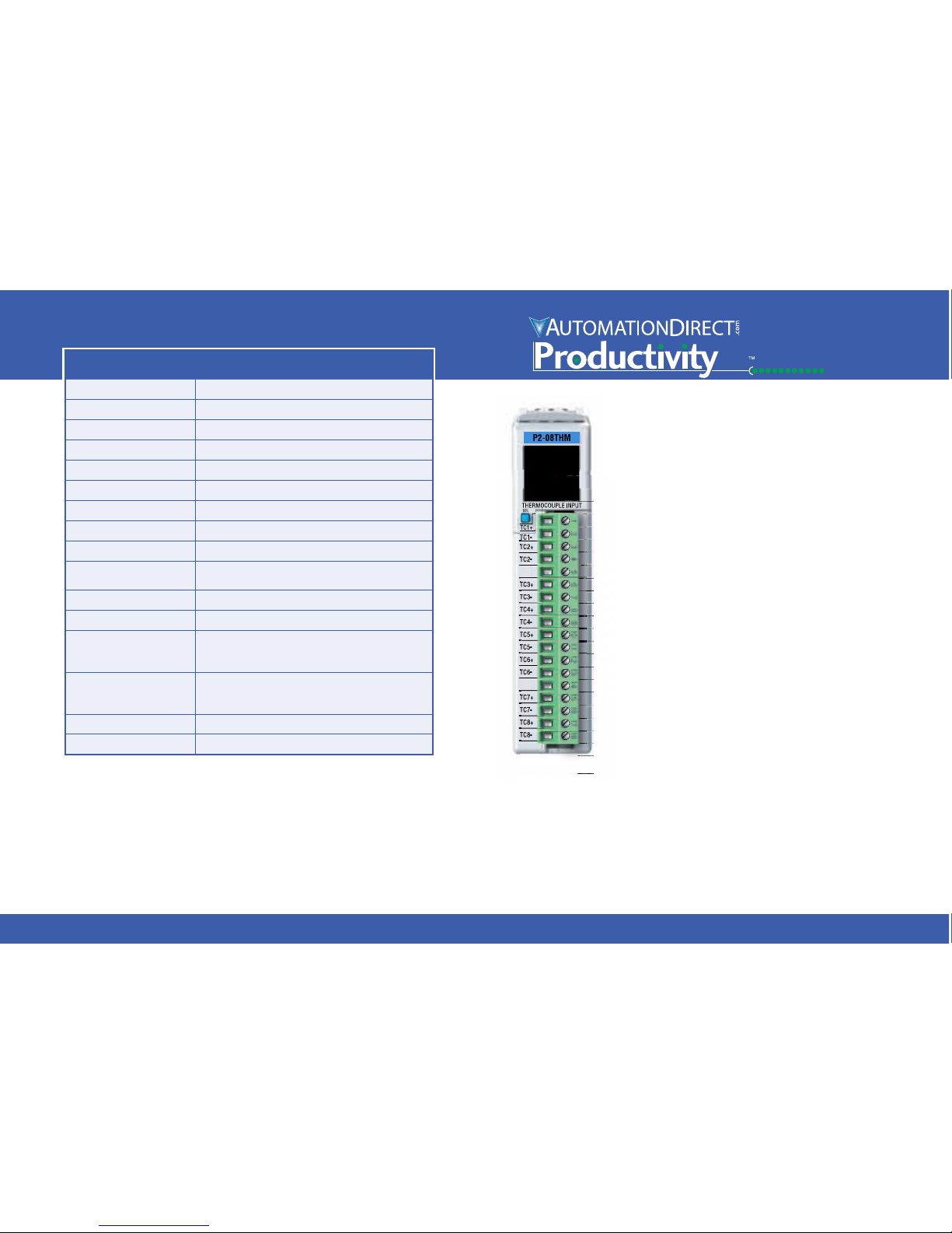
P2-08THM Analog Input
The P2-08THM Thermocouple Input Module
provides eight differential channels for receiving
thermocouple and voltage input signals for use
with the Productivity2000 System.
General Specifications ...................... 1
T/C Input Specifications ..................... 2
Voltage Input Specifications .................. 2
Configuration/Diagnostics .................... 2
Wiring Diagram and Schematic ................ 3
Module Installation Procedure ................. 4
QR Code ................................. 4
Hot Swap Information ....................... 4
Wiring Options ............................. 5
Module Configuration ....................... 5
Typical Application Example .................. 6
OLED Panel Display Menus .................. 7
Warning .................................. 8
Removable Terminal Block Specifications. . . . . . . . 8
General Specifications
Operating Temperature 0º to 60ºC (32º to 140ºF)
Storage Temperature -20º to 70ºC (-4º to 158ºF)
Humidity 5 to 95% (non-condensing)
Environmental Air No corrosive gases permitted
Vibration IEC60068-2-6 (Test Fc)
Shock IEC60068-2-27 (Test Ea)
Field to Logic Side Isolation 1800VAC applied for 1 second
Heat Dissipation 500mW
Enclosure Type Open Equipment
Agency Approvals
UL508 File E139594, Canada & USA
CE (EN61131-2*)
Module Keying to Backplane Electronic
Module Location Any I/O slot in a Productivity2000 System
Field Wiring
Removable terminal block (included).
The P2-08THM module is not compatible with the
ZIPLink wiring system.
EU Directive
See the “EU Directive” topic in the Productivity2000
Help File. Information can also be obtained at:
www.productivity2000.com
Connector Type (included) 18-position removable terminal block
Weight 90g (3.2 oz)
*Meets EMC and Safety requirements. See the D.O.C. for details.
Terminal Block Included. Not Compatible with ZIPLink.
Warranty: Thirty-day money-back guarantee. Two-year limited
replacement. (See www.productivity2000.com for details).
Page 2

2
Tech Support 770-844-4200www.productivity2000.com
T/C Input Specifications
Input Channels 8 Differential
Data Format Floating Point
Common Mode Range ±1.25 V
Common Mode Rejection 100dB @ DC and 130dB @ 60Hz
Input Impedance >5MΩ
Maximum Ratings Fault protected inputs to ±50V
Resolution 16-bit, ±0.1°C or °F
Thermocouple Input Ranges
Type J -190° to 760°C (-310° to 1400°F);
Type E -210° to 1000°C (-346° to 1832°F);
Type K -150° to 1372°C (-238° to 2502°F);
Type R 65° to 1768°C (149° to 3214°F);
Type S 65° to 1768°C (149° to 3214°F);
Type T -230° to 400°C (-382° to 752°F);
Type B 529° to 1820°C (984° to 3308°F);
Type N -70° to 1300°C (-94° to 2372°F);
Type C 65° to 2320°C (149° to 4208°F);
Cold Junction Compensation Automatic
Thermocouple Linearization Automatic
Accuracy vs. Temperature ±50ppm per °C (maximum)
Linearity Error
±1°C maximum (±0.5°C typical)
Monotonic with no missing codes
Maximum Inaccuracy
±3°C maximum (excluding thermocouple error)
(including temperature drift)
Warm-up Time
30 minutes for ±1% repeatability
2 minutes to reach voltage specifications
Sample Duration Time 270ms
All Channel Update Rate 2.16 s
Open Circuit Detection Time Within 2s
Conversion Method Sigma-Delta
External DC Power Required None
Voltage Input Specifications
Linear mV Device Input Ranges
0-39.0625 mVDC,
+/-39.0625 mVDC,
+/-78.125 mVDC,
0-156.25 mVDC,
+/-156.25 mVDC,
0-1250 mVDC
Max Voltage Input Offset Error 0.05% @ 0°- 60°C, typical 0.04% @ 25°C
Max Voltage Input Gain Error 0.06% @ 25°C
Max Voltage Input Linearity Error 0.05% @ 0°- 60°C, typical 0.03% @ 25°C
Max Voltage Input Impedance 0.2% @ 0° - 60°C, typical 0.06% @ 25°C
Configuration/Diagnostics
Burn-out Detection: High Side/Disable 1 bit per module
°C/°F (T/C Only) 1 bit per module
Module Diagnostics Failure 1 bit per module
Burn-out (on if T/C input is open – no connection
between TCn+ and TCn-)
1 bit per channel
Channel Under-range (T/C only) 1 bit per channel
Channel Over-range (T/C only) 1 bit per channel
Page 3
3
Sales 800-633-0405 www.productivity2000.com
AC or DC
AC or DC
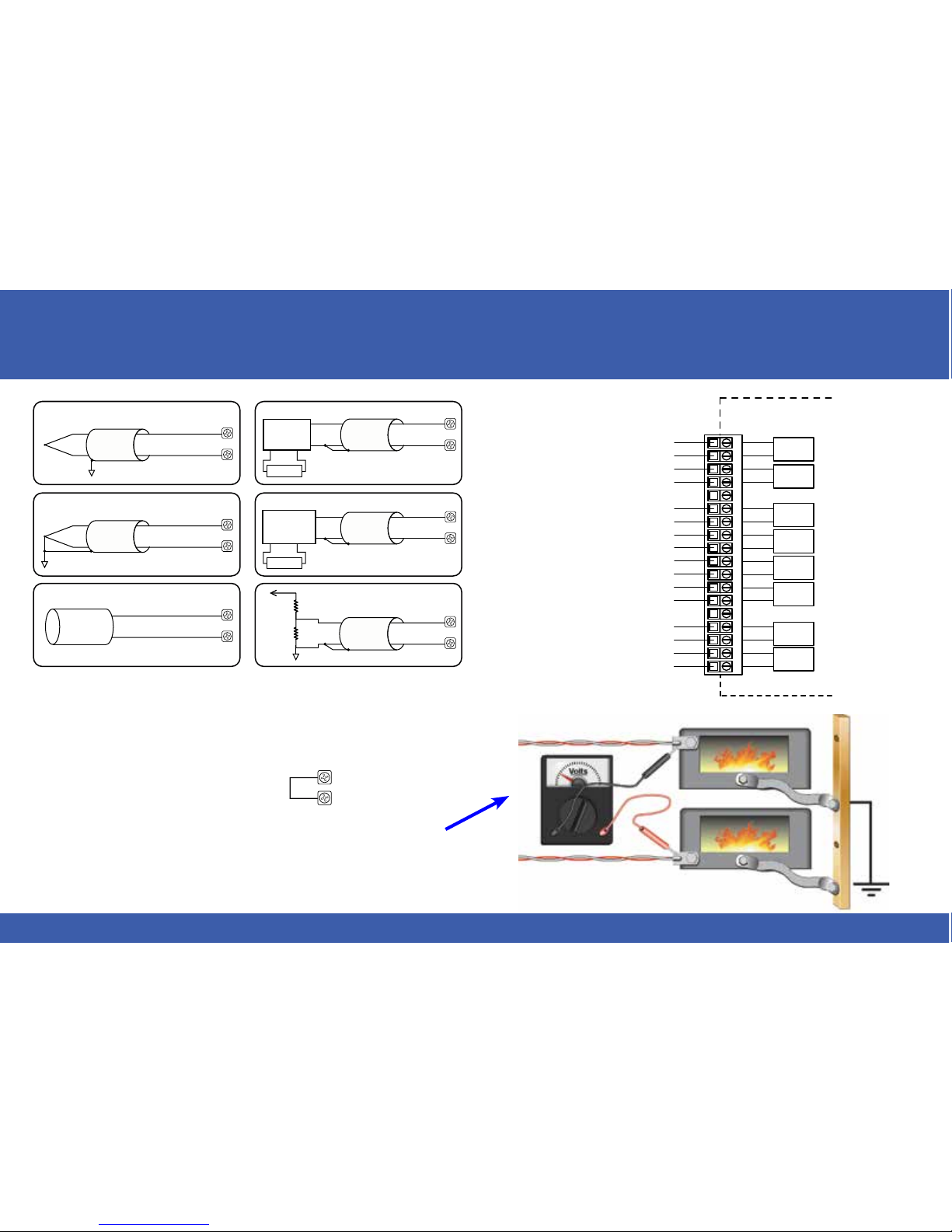
Thermocouple Input CircuitsVoltage Input Circuits
Excitation
Power Supply
Transmitter
Power Supply
Ungrounded/Shielded
Thermocouple
TC+
TC-
TC+
TC-
TC+
TC-
Grounded/Shielded
Thermocouple
Infrared
Thermocouple
4-wire
Voltage
Transmitter
Load Cell
or
Strain Gauge
Voltage Divider
TC+
TC-
TC+
TC-
TC+
TC-
TC1+
TC1TC2+
TC2-
TC3+
TC4+
TC3-
TC4TC5+
TC8+
TC8-
CH1 T/C
INPUT
INTERNAL
MODULE CIRCUITRY
TC5TC6+
TC6-
TC7+
TC7-
CH2 T/C
INPUT
CH3 T/C
INPUT
CH4 T/C
INPUT
CH5 T/C
INPUT
CH6 T/C
INPUT
CH7 T/C
INPUT
CH8 T/C
INPUT
12345678910 11 12 1813 14 15 16 17
Wiring Diagram Schematic
NOTES:
1. Connect shield to thermocouple signal/ground only. Do not connect to
both ends.
2. Install jumper wire on each unused input,
TC+ to TC-.
3. With grounded thermocouples, take precautions to prevent having a
voltage potential between thermocouple tips. A voltage of 1.25V or
greater between tips will skew measurements.
4. Use shielded, twisted thermocouple extension wire that matches the
thermocouple type. Use thermocouple-compatible junction blocks.
TC+
TC-
Page 4

4
Tech Support 770-844-4200www.productivity2000.com
Module Installation QR Code
Use any QR Code reader application to
display the module’s product insert.
Important Hot-Swap Information
The Productivity2000 System supports hot-swap!
Individual modules can be taken offline, removed, and
replaced while the rest of the system continues controlling your process. Before attempting to use the hotswap feature, be sure to read the hot-swap topic in the
programming software’s help file or our online documentation at AutomationDirect.com for details on how to plan
your installation for use of this powerful feature.
1 Align
with slot
2 rotate
to seated
position
WARNING: Do not apply field power until
the following steps are completed. See
hot-swapping procedure for
exceptions.
WIRE STRIP
LENGTH
WIRE STRIP
LENGTH
Step One: Align module
catch with base slot and
rotate module into
connector.
Locked
Unlocked
Step Two: Pull top locking tab
toward module face. Click indicates lock is
engaged.
Step Three: Attach field wiring to terminal block.
Caution: If possible, remove field power prior to
proceeding. If not, then EXTREME care MUST be taken
to prevent damage to the module, or even personal injury
due to a short circuit from the live terminal block.
Page 5

5
Sales 800-633-0405 www.productivity2000.com
Using the Hardware Configuration tool in the Productivity Suite
programming software, drag and drop the P2-08THM module
into the base configuratio
n.
Select Automatic Module Verification or No Verification and
Enable Hot Swap. Specify Temperature Scale and Burnout
Detection, and use the drop down menu to select module range
and resolution. If desired, assign a User Tagname to each input
point (channel) selected and to each Status Bit Item.
Wiring Options
1
Screw Terminal Block (Included)
P2-RTB
(Quantity 1)
2
Spring Clamp Terminal Block
P2-RTB-1
(Quantity 1)
Module Configuration
Page 6

6
Tech Support 770-844-4200www.productivity2000.com
Typical Application Example
Process
Variable
(feedback)
Heat
Controller
Heater
PID
Output
Oven
Temperature
User’s Desired
Setpoint
Thermocouple
to P2-08THM
P2-08THM
Module
Page 7

7
Sales 800-633-0405 www.productivity2000.com
Power On
Appears
initially
These screens will
then auto cycle
This screen will
auto cycle with
status information
PASSED
SELF
TEST
DISPLAY
SETUP
INFO
DISPLAY
UNITS
DECIMAL
COUNTS
DISPLAY
STATUS
INFO
P2-08THM
Fw. Rev.
1.00
16-BIT
7 CH
ENABLED
End of
Status
Menu
List
MISSING
CONFIG
DATA
End of
Status
Menu
List
SELFTEST
FAIL
REPLACE
MODULE
Hold SEL button down to cycle through primary screens. Release
button to
select
screen.
Error Messages:
An existing error
will be inserted
into the cycling
Status Info screen.
Momentarily
Press SEL
button to
toggle
through
secondary
displays
Note: Volts, Celsius, or
Fahrenheit values are
specified with the P2-08THM
Module Options configuration
dialog box in Productivity Suite
software.
Note: SPARE denotes
deselected channel.
1J 000°F
2E 000°F
3 00.0mV
4 0.000V
5 00.0mV
6 00.0mV
7 00.0mV
8 SPARE
1J 000°F
2E 000°F
3 00.0mV
4 0.000V
5 00.0mV
6 00.0mV
7 00.0mV
8 SPARE
Fault Messages
–
Appear in place
of data during a
fault condition.
Measured temperature > max. temperature of selected range.
Measured temperature < min. temperature of selected range.
Input signal is OPEN circuit. (Thermocouple only)
1 OVER
2 UNDER
3 OPEN
4
OLED Panel Display
Page 8

8
Tech Support 770-844-4200www.productivity2000.com
Document Name Edition/Revision Date
P2-08THM-DS 1st Ed. 8/15/2014
Copyright 2014, AutomationDirect.com Incorporated/All Rights Reserved Worldwide
WARNING: To minimize the risk of potential safety problems, you should
follow all applicable local and national codes that regulate the installation
and operation of your equipment. These codes vary from area to area and
it is your responsibility to determine which codes should be followed, and
to verify that the equipment, installation, and operation are in compliance
with the latest revision of these codes.
Equipment damage or serious injury to personnel can result from the
failure to follow all applicable codes and standards. We do not guarantee the products described in this publication are suitable for your
particular application, nor do we assume any responsibility for your
product design, installation, or operation.
If you have any questions concerning the installation or operation of this
equipment, or if you need additional information, please call Technical
Support at 770-844-4200.
This publication is based on information that was available at the time it
was printed. At AutomationDirect.com® we constantly strive to improve
our products and services, so we reserve the right to make changes to
the products and/or publications at any time without notice and without
any obligation. This publication may also discuss features that may not be
available in certain revisions of the product.
Removable Terminal Block Specifications
Part Number P2-RTB (included) P2-RTB-1
Number of
positions
18 Screw Terminals 18 Spring Clamp Terminals
Wire Range
30 - 16 AWG (0.051 - 1.31 mm²)
Solid / Stranded Conductor
3/64 in. (1.2 mm) Insulation Maximum
1/4 in (6 - 7 mm) Strip Length
28-16 AWG (0.081 - 1.31 mm²)
Solid / Stranded Conductor
3/64 in (1.2 mm) Insulation Maximum
19/64 in (7 - 8 mm) Strip Length
Conductors
Use Thermocouple Extension wire for thermocouples.
Use copper conductors, 75°C or equivalent for millivolt inputs.
Screw Driver
Width
1/8 in (3.8 mm) Maximum
Screw Size M2 N/A
Screw Torque 2.5 lb·in (0.28 N·m) N/A
 Loading...