

Page 1
Manual Number: P1AM-USER-M
Page 2

~ WARNING ~
Thank you for purchasing automation equipment from Automationdirect.com®, doing business as,
AutomationDirect. We want your new automation equipment to operate safely. Anyone who installs or
uses this equipment should read this publication (and any other relevant publications) before installing or
operating the equipment.
To minimize the risk of potential safety problems, you should follow all applicable local and national
codes that regulate the installation and operation of your equipment. These codes vary from area to area
and usually change with time. It is your responsibility to determine which codes should be followed, and
to verify that the equipment, installation, and operation is in compliance with the latest revision of these
codes.
At a minimum, you should follow all applicable sections of the National Fire Code, National Electrical
Code, and the codes of the National Electrical Manufacturer’s Association (NEMA). There may be local
regulatory or government offices that can also help determine which codes and standards are necessary for
safe installation and operation.
Equipment damage or serious injury to personnel can result from the failure to follow all applicable
codes and standards. We do not guarantee the products described in this publication are suitable for
your particular application, nor do we assume any responsibility for your product design, installation, or
operation.
Our products are not fault-tolerant and are not designed, manufactured or intended for use or resale as
on-line control equipment in hazardous environments requiring fail-safe performance, such as in the
operation of nuclear facilities, aircraft navigation or communication systems, air traffic control, direct life
support machines, or weapons systems, in which the failure of the product could lead directly to death,
personal injury, or severe physical or environmental damage (“High Risk Activities”). AutomationDirect
specifically disclaims any expressed or implied warranty of fitness for High Risk Activities.
For additional warranty and safety information, see the Terms and Conditions section of our catalog.
If you have any questions concerning the installation or operation of this equipment, or if you need
additional information, please call us at 770-844-4200.
This publication is based on information that was available at the time it was printed. At
AutomationDirect we constantly strive to improve our products and services, so we reserve the right to
make changes to the products and/or publications at any time without notice and without any obligation.
This publication may also discuss features that may not be available in certain revisions of the product.
Trademarks
This publication may contain references to products produced and/or offered by other companies. The
product and company names may be trademarked and are the sole property of their respective owners.
AutomationDirect disclaims any proprietary interest in the marks and names of others.
Copyright© 2020, Automationdirect.com® Incorporated
No part of this manual shall be copied, reproduced, or transmitted in any way without the prior, written
consent of Automationdirect.com® Incorporated. AutomationDirect retains the exclusive rights to all
information included in this document.
All Rights Reserved
Page 3

~ ADVERTENCIA ~
Gracias por comprar equipo de automatización de Automationdirect.com®. Deseamos que su nuevo equipo
de automatización opere de manera segura. Cualquier persona que instale o use este equipo debe leer esta
publicación (y cualquier otra publicación pertinente) antes de instalar u operar el equipo.
Para reducir al mínimo el riesgo debido a problemas de seguridad, debe seguir todos los códigos de seguridad
locales o nacionales aplicables que regulan la instalación y operación de su equipo. Estos códigos varian de
área en área y usualmente cambian con el tiempo. Es su responsabilidad determinar cuales códigos deben ser
seguidos y verificar que el equipo, instalación y operación estén en cumplimiento con la revisión mas reciente
de estos códigos.
Como mínimo, debe seguir las secciones aplicables del Código Nacional de Incendio, Código Nacional Eléctrico,
y los códigos de (NEMA) la Asociación Nacional de Fabricantes Eléctricos de USA. Puede haber oficinas de
normas locales o del gobierno que pueden ayudar a determinar cuales códigos y normas son necesarios para una
instalación y operación segura.
Si no se siguen todos los códigos y normas aplicables, puede resultar en daños al equipo o lesiones serias a
personas. No garantizamos los productos descritos en esta publicación para ser adecuados para su aplicación
en particular, ni asumimos ninguna responsabilidad por el diseño de su producto, la instalación u operación.
Nuestros productos no son tolerantes a fallas y no han sido diseñados, fabricados o intencionados para uso
o reventa como equipo de control en línea en ambientes peligrosos que requieren una ejecución sin fallas,
tales como operación en instalaciones nucleares, sistemas de navegación aérea, o de comunicación, control de
tráfico aéreo, máquinas de soporte de vida o sistemas de armamentos en las cuales la falla del producto puede
resultar directamente en muerte, heridas personales, o daños físicos o ambientales severos (“Actividades de Alto
Riesgo”). Automationdirect.com específicamente rechaza cualquier garantía ya sea expresada o implicada
para actividades de alto riesgo.
Para información adicional acerca de garantía e información de seguridad, vea la sección de Términos
y Condiciones de nuestro catálogo. Si tiene alguna pregunta sobre instalación u operación de este equipo, o
si necesita información adicional, por favor llámenos al número 770-844-4200 en Estados Unidos.
Esta publicación está basada en la información disponible al momento de impresión. En Automationdirect.
com nos esforzamos constantemente para mejorar nuestros productos y servicios, así que nos reservamos el
derecho de hacer cambios al producto y/o a las publicaciones en cualquier momento sin notificación y sin
ninguna obligación. Esta publicación también puede discutir características que no estén disponibles en ciertas
revisiones del producto.
Marcas Registradas
Esta publicación puede contener referencias a productos producidos y/u ofrecidos por otras compañías. Los nombres de las
compañías y productos pueden tener marcas registradas y son propiedad única de sus respectivos dueños. Automationdirect.com,
renuncia cualquier interés propietario en las marcas y nombres de otros.
PROPIEDAD LITERARIA
No se permite copiar, reproducir, o transmitir de ninguna forma ninguna parte de este manual sin previo consentimiento por escrito
de Automationdirect.com
este documento. Los usuarios de este equipo pueden copiar este documento solamente para instalar, configurar y mantener el equipo
correspondiente. También las instituciones de enseñanza pueden usar este manual para propósitos educativos.
®
Incorprated. Automationdirect.com retiene los derechos exclusivos a toda la información incluida en
©
2020, AUTOMATIONDIRECT.COM® INCORPORATED
Todos los derechos reservados
Page 4

~ AVERTISSEMENT ~
Nous vous remercions d’avoir acheté l’équipement d’automatisation de Automationdirect.com®, en faisant des
affaires comme, AutomationDirect. Nous tenons à ce que votre nouvel équipement d’automatisation fonctionne en
toute sécurité. Toute personne qui installe ou utilise cet équipement doit lire la présente publication (et toutes les
autres publications pertinentes) avant de l’installer ou de l’utiliser.
Afin de réduire au minimum le risque d’éventuels problèmes de sécurité, vous devez respecter tous les codes locaux
et nationaux applicables régissant l’installation et le fonctionnement de votre équipement. Ces codes diffèrent d’une
région à l’autre et, habituellement, évoluent au fil du temps. Il vous incombe de déterminer les codes à respecter et
de vous assurer que l’équipement, l’installation et le fonctionnement sont conformes aux exigences de la version la
plus récente de ces codes.
Vous devez, à tout le moins, respecter toutes les sections applicables du Code national de prévention des incendies,
du Code national de l’électricité et des codes de la National Electrical Manufacturer’s Association (NEMA). Des
organismes de réglementation ou des services gouvernementaux locaux peuvent également vous aider à déterminer
les codes ainsi que les normes à respecter pour assurer une installation et un fonctionnement sûrs.
L’omission de respecter la totalité des codes et des normes applicables peut entraîner des dommages à l’équipement
ou causer de graves blessures au personnel. Nous ne garantissons pas que les produits décrits dans cette publication
conviennent à votre application particulière et nous n’assumons aucune responsabilité à l’égard de la conception, de
l’installation ou du fonctionnement de votre produit.
Nos produits ne sont pas insensibles aux défaillances et ne sont ni conçus ni fabriqués pour l’utilisation ou la revente
en tant qu’équipement de commande en ligne dans des environnements dangereux nécessitant une sécurité absolue,
par exemple, l’exploitation d’installations nucléaires, les systèmes de navigation aérienne ou de communication, le
contrôle de la circulation aérienne, les équipements de survie ou les systèmes d’armes, pour lesquels la défaillance du
produit peut provoquer la mort, des blessures corporelles ou de graves dommages matériels ou environnementaux
(«activités à risque élevé»). La société AutomationDirect nie toute garantie expresse ou implicite d’aptitude à
l’emploi en ce qui a trait aux activités à risque élevé.
Pour des renseignements additionnels touchant la garantie et la sécurité, veuillez consulter la section Modalités et
conditions de notre documentation. Si vous avez des questions au sujet de l’installation ou du fonctionnement de cet
équipement, ou encore si vous avez besoin de renseignements supplémentaires, n’hésitez pas à nous téléphoner au
770-844-4200.
Cette publication s’appuie sur l’information qui était disponible au moment de l’impression. À la société
AutomationDirect, nous nous efforçons constamment d’améliorer nos produits et services. C’est pourquoi nous
nous réservons le droit d’apporter des modifications aux produits ou aux publications en tout temps, sans préavis ni
quelque obligation que ce soit. La présente publication peut aussi porter sur des caractéristiques susceptibles de ne
pas être offertes dans certaines versions révisées du produit.
Marques de commerce
La présente publication peut contenir des références à des produits fabriqués ou offerts par d’autres entreprises. Les
désignations des produits et des entreprises peuvent être des marques de commerce et appartiennent exclusivement à
leurs propriétaires respectifs. AutomationDirect nie tout intérêt dans les autres marques et désignations.
Copyright© 2019, Automationdirect.com® Incorporated
Nulle partie de ce manuel ne doit être copiée, reproduite ou transmise de quelque façon que ce soit sans le
consentement préalable écrit de la société Automationdirect.com® Incorporated. AutomationDirect conserve les
droits exclusifs à l’égard de tous les renseignements contenus dans le présent document.
Tous droits réservés
Page 5

ProductivityOpen User Manual
Please include the Manual Number and the Manual Issue, both shown below,
when communicating with Technical Support regarding this publication.
Manual Number: P1AM-USER-M
Issue: 1st Edition, Rev. A
Issue Date: 02/2020
Publication History
Issue Date Description of Changes
1st Edition 01/2020 Original
1st Ed. Rev. A 02/2020 Added Appendix A - Networks Security material.
Page 6

Table of ConTenTs
Chapter 1 - Getting Started
Introduction .............................................................................................................. 1–2
Intended Use of This Product ..................................................................................1–2
Purpose of this Manual ..........................................................................................1–3
Important Online Resources .....................................................................................1–3
Conventions Used ...................................................................................................... 1–4
Key Topics for Each Chapter ..................................................................................... 1–4
Install Programming Software .................................................................................. 1–5
Mounting Hardware .................................................................................................. 1–8
Power the System ...................................................................................................... 1–9
Chapter 2 - Specifications
Overview ................................................................................................................... 2–2
Right Side Expansion - Productivity1000 Input/output Modules ............................... 2–2
Left Side Expansion - Arduino MKR-compatible Shields ........................................... 2–2
P1AM-100 Arduino Compatible CPU ........................................................................ 2–3
P1AM-100 Module Faceplate Layout ........................................................................ 2–4
P1AM-100 MicroB USB Programming Port ............................................................... 2–5
microSD Slot ............................................................................................................ 2–6
P1AM-100 CPU Headers ...........................................................................................2–7
Powering Your ProductivityOpen System ..................................................................2–8
AutomationDirect Shields .........................................................................................2–9
Ethernet Communications Shield .............................................................................2–9
Header Pin Breakout Module .................................................................................. 2–11
I/O Modules Overview ............................................................................................2–13
Page 7

Table of Contents
Chapter 3 - Installation and Wiring
Safety Guidelines ....................................................................................................... 3–3
Plan for Safety .......................................................................................................... 3–3
Three Levels of Protection ........................................................................................3–4
Orderly System Shutdown ........................................................................................3–4
System Power Disconnect ........................................................................................3–4
Emergency Stop Circuits ..........................................................................................3–5
Introduction to the ProductivityOpen Mechanical Design ...................................... 3–6
Typical P1AM-100 ....................................................................................................3–6
Dimensions and Installation ...................................................................................... 3–7
Basic Dimensions .......................................................................................................3–9
Mounting Guidelines ............................................................................................... 3–12
Enclosures ..............................................................................................................3–12
Mounting Position ..................................................................................................3–12
Using Mounting Rails .............................................................................................3–12
Mounting Clearances .............................................................................................3–13
Temperature Considerations ................................................................................... 3–13
Power Considerations ............................................................................................. 3–13
Grounding .............................................................................................................3–14
Agency Approvals ...................................................................................................3–14
DIN Rail Mounting P1AM-100 System ....................................................................3–15
Surface Mounting P1AM-100 System ..................................................................... 3–15
Installing the I/O Modules ...................................................................................... 3–16
Wiring Guidelines ....................................................................................................3–17
Power Supply Wiring .............................................................................................. 3–17
Grounding .............................................................................................................3–17
Fuse Protection .......................................................................................................3–18
I/O Module Wiring Options ....................................................................................3–19
Hand Wiring System ............................................................................................... 3–19
ZIPLink Wiring System ...........................................................................................3–20
Terminal Block With Pigtail Cable ........................................................................... 3–20
Input and Output Modules ZIPLink Selections .......................................................3–21
Analog Modules ZIPLink Selections ........................................................................ 3–22
ii
Hardware User Manual, 1st Ed. Rev. A
Page 8

Table of Contents
Removable Terminal Blocks (Optional) ................................................................... 3–23
P1-10RTB and P1-10RTB-1 .....................................................................................3–23
P2-RTB and P2-RTB-1 .............................................................................................3–23
Terminal Block Installation ...................................................................................... 3–24
Terminal Block Removal .......................................................................................... 3–25
Planning the I/O Wiring Routes .............................................................................. 3–25
System Wiring Strategies ........................................................................................3–26
CPU Isolation Boundaries .......................................................................................3–26
Sinking/Sourcing Concepts ....................................................................................3–27
I/O “Common Terminal” Concepts ........................................................................ 3–28
DC Input Wiring Methods ...................................................................................... 3–29
DC Output Wiring Methods ................................................................................... 3–29
Relay Outputs - Wiring Methods ............................................................................3–31
Relay Outputs – Transient Suppression for Inductive Loads in a Control System ..... 3–32
Appendix A - Security Considerations for Controls Networks
Security Considerations for Controls Networks .......................................................A–2
Hardware User Manual, 1st Ed. Rev. A
iii
Page 9

Chapter
Chapter
Chapter
GettinG Started
1
1
1
In This Chapter...
Introduction .............................................................................................................. 1–2
Intended Use of This Product ..................................................................................1–2
Purpose of this Manual ..........................................................................................1–3
Important Online Resources .....................................................................................1–3
Conventions Used ...................................................................................................... 1–4
Key Topics for Each Chapter ..................................................................................... 1–4
Install Programming Software .................................................................................. 1–5
Mounting Hardware .................................................................................................. 1–8
Power the System ...................................................................................................... 1–9
Page 10

Chapter 1: Getting Started
Introduction
Intended Use of This Product
The PIAM-100 is a small computer with on-board I/O based on the “Open-Source Arduino
platform”. This product can be used to solve various control and automation tasks using
customized programs.
The user community website of PIAM-100 (http://go2adc.com/p1am) is where you will find
various demo programs and libraries that will allow you to jump right into programming and
design.
Follow all applicable safety parameters when connecting to external I/O sensors and devices.
Any use other than described in this manual is not permitted, as this may expose the user to
possible harm and/or damage to the device or connected equipment.
The P1AM-100 must not be altered or modified. The safety instructions as well as the
maximum permissible ambient conditions and operating parameters are given in Chapter 2
“Technical Specifications”.
The instruction manual is meant to be read thoroughly while being mindful of safe and
proper operation. It contains important information on mounting, operating and handling
the P1AM-100.
CAUTION: The P1AM CPU Base Controller uses pins A3 and A4 so any shield that uses these same pins
will have a conflict. The MKR RGB shield is one that has this conflict.
1–2
Hardware User Manual, 1st Ed. Rev. A
Page 11

Chapter 1: Getting Started
Purpose of this Manual
Thank you for purchasing the AutomationDirect ProductivityOpen Arduino compatible
Controller. This user manual provides information that will help you install, set up, program,
troubleshoot, and maintain your ProductivityOpen project.
The manual includes information that is critical to the safety of the personnel who will install
and use the controller and to the machinery, processes, and equipment controlled by the
P1AM-100.
The manual also includes important information about power and signal wiring, mounting the
CPU and modules, and configuring the system.
Important Online Resources
Access to ADC Community based help for your ProductivityOpen projects is available from
our website: http://go2adc.com/p1am.
You will need libraries and other files available from our GitHub page at
https://github.com/facts-engineering/P1AM
The P1AM libraries and Board Support Package and other support files are located on Github.
A variety of other useful information about the Productivity1000 I/O modules, as well as code
for example tasks and more is available at https://facts-engineering.github.io.
The P1AM-100 may be programmed by Arduino IDE which may be downloaded from
https://www.arduino.cc/en/Main/Software. A graphical programming tool customized for
P1AM-100 based on ArduBlock (ProductivityBlocks® )is accessible from the Tools menu in the
Arduino IDE.
In addition, the Productivity1000 series power supplies and I/O modules, which work with the
P1AM-100, include an installation insert.
Use a QR symbol reader or click on graphic icon to see an overview video.
Hardware User Manual, 1st Ed. Rev. A
1–3
Page 12

Chapter 1: Getting Started
Conventions Used
NOTE: When you see the “note pad” icon in the left-hand margin, the paragraph to its immediate right will be
a special note. Notes represent information that may make your work quicker or more efficient. The word
NOTE in boldface will mark the beginning of the text.
When you see the “exclamation point” icon in the left-hand margin, the paragraph to its immediate right
will be a warning. This information could prevent injury, loss of property, or even death in extreme
cases. Any warning in this manual should be regarded as critical information that should be read in its
entirety. The word WARNING in boldface will mark the beginning of the text.
Key Topics for Each Chapter
The beginning of each chapter will list the key
topics that can be found in that chapter.
1–4
Hardware User Manual, 1st Ed. Rev. A
Page 13

Install Programming Software
NOTE: An active Internet connection is required to download the Arduino IDE and access the libraries and
board driver.
The P1AM-100 CPU may be programmed with the Arduino IDE. ProductivityBlocks® is
an optional graphical environment used with the IDE that AutomationDirect has adapted to
make Productivity1000 I/O modules conveniently accessible as blocks.
1. Download the latest version of the Arduino IDE software
from https://www.arduino.cc/en/Main/Software.
2. Library Install:
a. In the Arduino IDE go to “Sketch -> Include Library -> Manage Libraries…”
b. Leave the Type and Topic filters as “All” and type “P1AM” in the “Filter your search…” box
c. Click on the P1AM by FACTS Engineering that appears
d. Click the Install button
e. Close the Library Manager window
f. Confirm the installation by checking for “File -> Examples -> P1AM-100”. Several categories
of examples should be present.
Productivity
Blocks
CC
Chapter 1: Getting Started
Hardware User Manual, 1st Ed. Rev. A
1–5
Page 14

Chapter 1: Getting Started
3. Arduino Board Support Package Install:
a. Go to “File->Preferences” and paste the following link into the “Additional Boards Manager
URLs” field.
NOTE: Make sure you right click on the link and choose “Copy Link”.
i. https://raw.githubusercontent.com/facts-engineering/facts-engineering.github.io/master/
package_productivity-P1AM-boardmanagermodule_index.json
b. Go to “Tools -> Boards -> Board Manager”. Type P1AM into the search box at the top.
Mouse over the result and click install. The install may take several minutes to complete.
c. If you are on a version of Windows before Windows 10 this is mandatory. For Windows
10 users, this may be run if you want the board to appear as P1AM-100 in device
manager.
i. Download the “driver install” file from this link:
https://github.com/facts-engineering/P1AMCore/raw/master/drivers.zip.
ii. Extract the file
iii. Run the “P1AM-100_install.bat” file to complete the driver installation.
d. If you are having trouble installing the BSP due to network issues such as firewall
restrictions, you can use the “Arduino SAMD Boards” (specifically the MKRZERO) as
an alternative. These are present in the board manager automatically.
4. Testing installation
a. Attach the modules and/or shields you wish to use. REMEMBER modules/shields must not
be connected or disconnected while power is applied - either 24V or USB.
b. Plug the micro USB cable into the P1AM-100 and computer
i. If using P1000 I/O modules power the system with 24V
c. Go to “Tools -> Board:” and select “P1AM-100” from the dropdown that appears.
d. Go to “Tools -> Port” and select the “P1AM-100” device that you have plugged in.
e. Go to File -> Examples -> P1AM-100->Basic->PrintModules to open the Print Modules
example. Note that the PrintModules example is intended for a system with Productivity1000
modules connected and powered.
f. Click the right facing arrow button under “Edit” to upload the code to the board.
g. Go to “Tools -> Serial Monitor” and check to see that the name of module(s) you have in the
base is printing to the terminal.
1–6
Hardware User Manual, 1st Ed. Rev. A
Page 15

Productivity
Blocks
Chapter 1: Getting Started
5. Next Steps
a. Start with the “Basic” category of the P1AM-100 Library examples to become familiar with
the API.
b. Once you are comfortable with the basic examples you can move on to more complex
routines included in the P1AM-100 examples.
6. Install ProductivityBlocks
a. Run the ProductivityBlocks Installer.
b. ProductivityBlocks will be installed in the Documents -> ProductivityBlocks folder. The
ProductivityBlocks programming environment is accessible from the Tools menu in the
Arduino IDE.
c. Example ProductivityBlocks programs are also included in this folder.
®
Hardware User Manual, 1st Ed. Rev. A
1–7
Page 16
Chapter 1: Getting Started
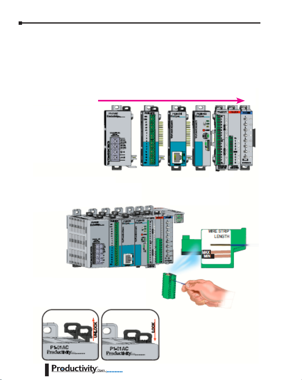
Mounting Hardware
Install Shields on the left side of the P1AM CPU and P1 I/O Modules on the right side of the
P1AM CPU.
The ProductivityOpen Shields and Productivity1000 Input/Output modules are DIN rail
mountable and designed to snap together to simplify connection. A system may include
communications, inputs and outputs. See Chapter 3 of this manual and Chapters 4 and 5 of
the Productivity1000 manual for more detailed hardware installation information.
!WARNING! Do not add or remove modules with field power applied!
Step One:
With latch in “locked” position,
align connectors on the side of
each module and stack by pressing
together. An audible click indicates
lock is engaged.
Step Two:
Attach field wiring using the removable
terminal block or ZIPLink wiring system.
Step Three:
To unstack modules, pull locking latch up
into the unlocked position and then pull
modules apart.
CAUTION: Ensure all latches
are secured after modules
are connected.
1–8
Hardware User Manual, 1st Ed. Rev. A
Page 17

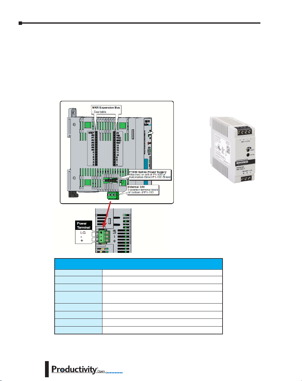
Power the System
NOTE: Ensure all modules are connected to the system before power is applied. Do not assemble or
disassemble the system while power is applied.
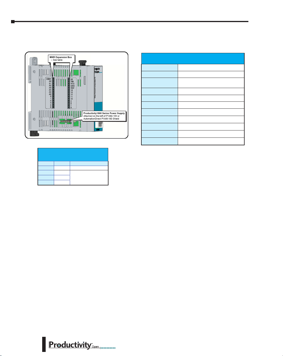
Productivity1000 Power Supplies:
1. Connect one of the Productivity1000 power supplies to P1AM-100. Should you choose
Arduino MKR compatible shields instead of or in addition to the ProductivityOpen shields,
the Productivity1000 power supplies cannot be used. In this case an alternative power supply
is required (See below for information on connecting an external power supply).
P1000 24VDC input power supplies:
• P1-01AC: AC Input 85–132 / 170–264 VAC, 16W
(power for P1AM-100 and up to 8 modules)
• P1-02AC: AC Input 85–132 / 170–264 VAC, 26W
(power for P1AM-100 and up to 15 modules)
• P1-01DC: DC Input 12–24 VDC, 16W
(power for P1AM-100 and up to 8 modules)
Chapter 1: Getting Started
P1-01AC
100-240V 48VA
125VDC, 20W
®
50-60Hz
P1-01AC
AC (L)
DC (+V)
AC (N)
DC (-V)
LG
P1-02AC
™
100-240V 74VA
50-60Hz
125VDC, 33W
AC (L)
DC (+V)
AC (N)
DC (-V)
G
G
LG
P1-02AC
P1-01DC
12-24V 21W
P1-01DC
™
+V
-V
G
LG
CAUTION: Ensure that only one power supply source is connected to the Arduino system. When a
Productivity1000 power supply is connected immediately to the left of the CPU module, the bottom Power
Connector must be removed before connecting P1-01AC Power Supply. This precludes connection of two
separate power supplies. If an AutomationDirect shield is connected between a Productivity1000 power
supply and the CPU module care must be taken to ensure an external power supply is not connected to the
bottom terminals.
Hardware User Manual, 1st Ed. Rev. A
1–9
Page 18
Chapter 1: Getting Started
2. OR using an alternative 24VDC external power source connect directly to P1AM-100 Optional
Power Connector terminals. This option allows for the use of Input/Output modules from the
Productivity1000 family as well as all Arduino MKR compatible shields.
• The LG and minus terminals on the external power supply connection are internally
shorted.
• Use separate 24VDC supplies, one for the P1AM-100 and another for inductive loads to
keep the P1AM-100 supply power clean and free of voltage spikes caused by switching
inductive loads.
RHINO Power Supply
P/N PSV24-50s
Example of Alternative
24VDC Power Supply
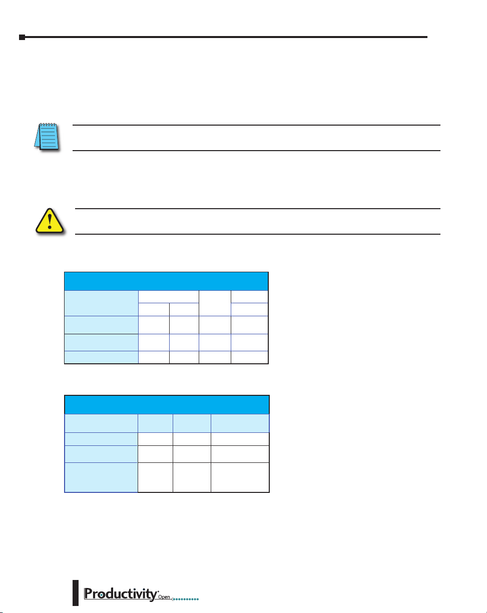
1–10
Terminal Block Specications
Part Number
Number of positions
Pitch
Wire Range
Conductors
Screw Driver Width
Screw Size
Screw Torque
*Recommended screw driver P/N: TW-SD-MSL-2
PCON-KIT
3 screw terminals
3.5 mm
28–16 AWG (0.324 to 3.31 mm²) Solid / Stranded conductor
1/4 in (6–7 mm) Strip Length
Use copper conductors, 75°C or equivalent
1/8 in (3.175 mm) Maximum
M2
1.7 lb·in (0.4 N·m)
Hardware User Manual, 1st Ed. Rev. A
Page 19
Chapter 1: Getting Started
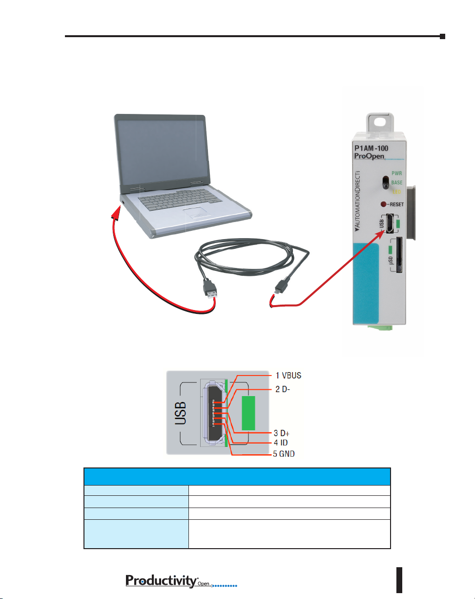
3. OR using USB input power, connect to the microB USB port on the face of the P1AM-100.
USB power is intended for programming and will not power Productivity1000 Input /output
modules.
Micro USB Type B Input Specications
Port Name
Description
Port Status LED
Cables
Micro USB
Standard Micro USB input for programming and monitoring
Green LED is illuminated when a power cable is plugged in.
USB Type A to Micro USB Type B:
6ft cable part # USB-CBL-AMICB6
15ft cable part # USB-CBL-AMICB15
Hardware User Manual, 1st Ed. Rev. A
1–11
Page 20

Chapter
Chapter
Chapter
SpecificationS
2
2
2
In This Chapter...
Overview ................................................................................................................... 2–2
Right Side Expansion - Productivity1000 Input/output Modules ............................... 2–2
Left Side Expansion - Arduino MKR-compatible Shields ........................................... 2–2
P1AM-100 Arduino Compatible CPU ........................................................................ 2–3
P1AM-100 Module Faceplate Layout ........................................................................ 2–4
P1AM-100 MicroB USB Programming Port ............................................................... 2–5
microSD Slot ............................................................................................................ 2–6
P1AM-100 CPU Headers ...........................................................................................2–7
Powering Your ProductivityOpen System ..................................................................2–8
AutomationDirect Shields .........................................................................................2–9
Ethernet Communications Shield .............................................................................2–9
Header Pin Breakout Module .................................................................................. 2–11
I/O Modules Overview ............................................................................................2–13
Page 21
Chapter 2: Specifications
Overview
The ProductivityOpen system is intended to provide a robust selection of components for a
compact and expandable design with a simple-to-use philosophy.
Right Side Expansion - Productivity1000 Input/output Modules
The P1AM-100 can be expanded with the addition of easily connected I/O modules and does
not require a mounting base. I/O modules are connected via an expansion port on the right
side of the P1AM-100 case. A variety of I/O modules are available from the Productivity1000
series for flexible and optimal system configuration. Refer to the Productivity1000 user manual
for detailed descriptions (https://cdn.automationdirect.com/static/manuals/p1userm/
p1userm.html).
Left Side Expansion - Arduino MKR-compatible Shields
The left side of the case allows expansion with most* Arduino MKR compatible shields.
A selection of shields to support P1AM-100 in housings to conveniently connect to the
P1AM-100 specifically are available from AutomationDirect. See detailed descriptions
following.
* NOTE: The P1AM CPU Base Controller uses pins A3 and A4 so any shield that uses these same pins will
have a conflict. The MKR RGB shield is one that has this conflict.
2–2
Hardware User Manual, 1st Ed. Rev. A
Page 22
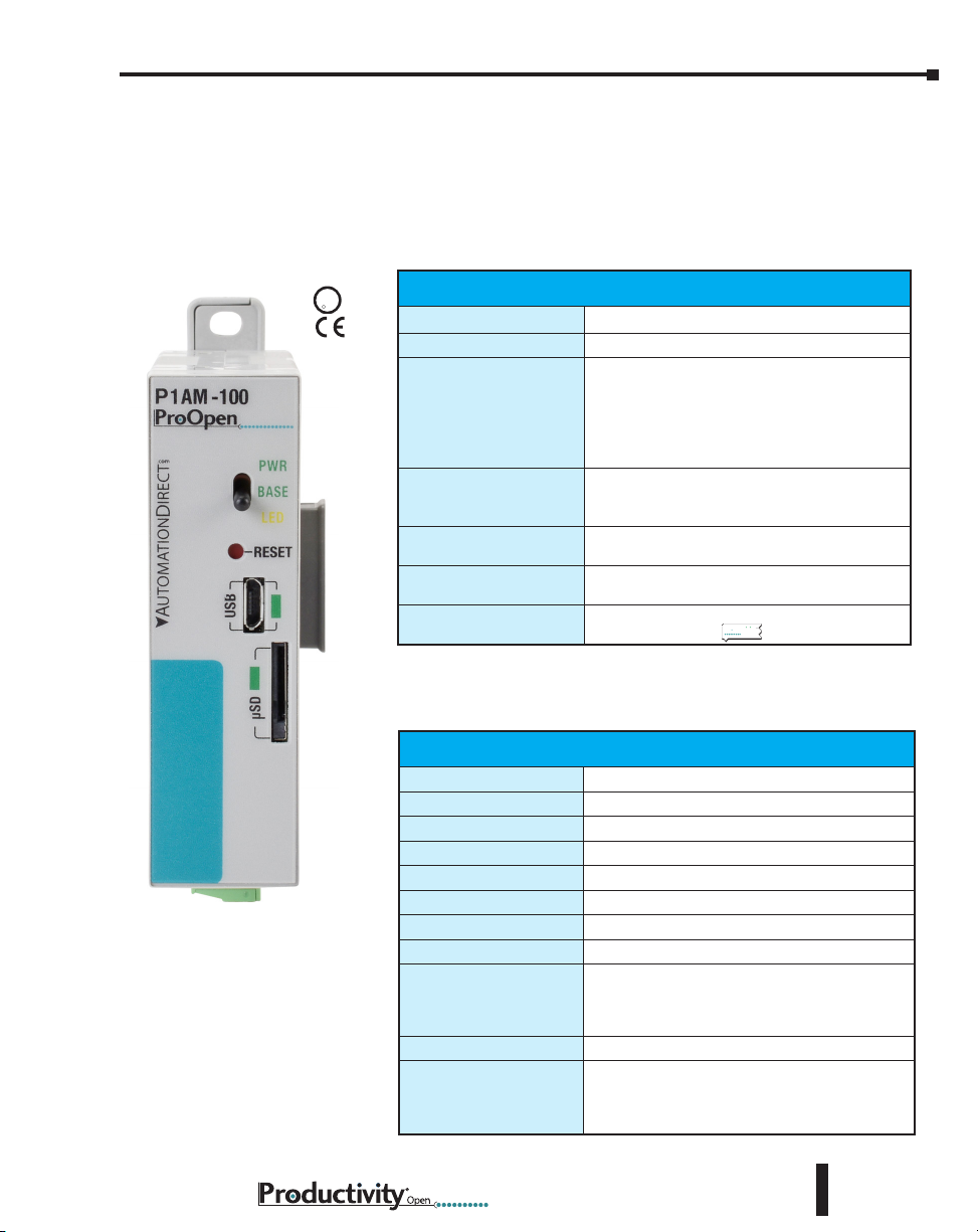
P1AM-100 Arduino Compatible CPU
U
L
C
US
The P1AM-100 is an Arduino-compatible CPU. It uses the Atmel SAMD21G18 microcontroller and can be programmed using Arduino IDE or ProductivityBlocks®. It interfaces
with all Productivity1000 Series I/O modules connected to the right side of the P1AM-100
and most Arduino MKR form factor shields connected to the left side. The specifications are
listed in the tables below.
Chapter 2: Specifications
P1AM-100
R
User Specications
User Memory
Memory Type
Base Controller and I/O
Power Requirement
Recommended Fuse
(External)
Peripherals
Hardware Limits of System
Programming
¹ If you do not use a Productivity1000 power supply, like the P1-01AC, then use a power supply that has
transformer isolation. Use different 24VDC supplies for the CPU and inductive loads to keep the CPU power
clean and free of voltage spikes caused by switching solenoids, motors and relay coils.
² See MKR Expansion Bus table and notes for shield power budget restrictions.
1
256kB Flash with 10kB used for bootloader
Flash: 256kB, SRAM: 32kB
24VDC ±2%
Plan 0.5 W for the SAMD chip and base controller
Plan 1.25 W per P1000 I/O module
Plan 9W for max. header power draw (which
provides max. 4.25 W power to left side connected
shields).
Edison S5061-R, Time Delay, 1A Fuse
For 9–15 modules: Edison S5062-R, Time Delay,
2A Fuse
MicroB USB, Arduino MKR-compatible, microSD
card slot, User controlled LED
15 Productivity1000 I/O Modules; Arduino MKR
2
shields
Programmed in C/C++ with the Arduino IDE or
ProductivityBlocks
®
Productivity
Blocks
General Specications
Operating Temperature
Storage Temperature
Humidity
Environmental Air
Vibration
Shock
Heat Dissipation
Enclosure Type
Module Location
Weight
Agency Approvals
0° to 60°C (32° to 140°F)
-20° to 70°C (-4° to 158°F)
5 to 95% (non-condensing)
No corrosive gases permitted
IEC60068-2-6 (Test Fc)
IEC60068-2-27 (Test Ea)
4000mW
Open Equipment
Productivity1000 I/O modules connect on the right
side of module. Productivity1000 power supply,
P1AM Shields and MKR Shields connect on the left
side on the module.
76g (2.8 oz)
UL 61010-1 and UL 61010-2-201 File E139594,
Canada & USA
CE (EN 61131-2 EMC, EN 61010-1 and EN 610102-201 Safety)
Hardware User Manual, 1st Ed. Rev. A
2–3
Page 23
Chapter 2: Specifications
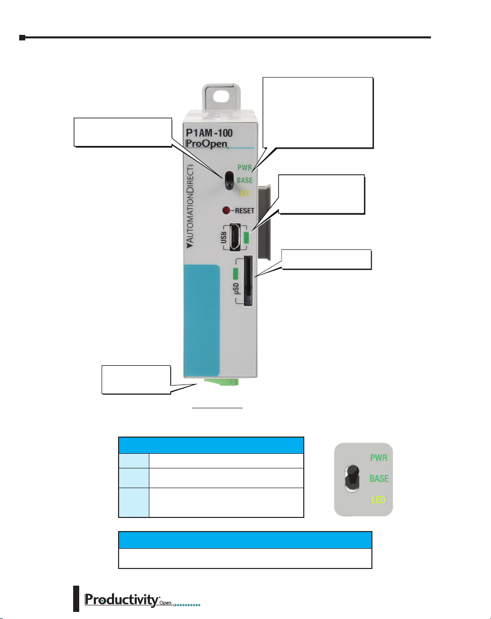
P1AM-100 Module Faceplate Layout
Toggle Switch
- Tied to SWITCH_BUILTIN
or Digital Pin 31
CPU Status Indicators
- PWR LED indicates
power applied
- BASE LED indicates when
base controller is powered
and initialized
- LED controlled by writing to
LED_BUILTIN or Digital Pin 32
Power Option for the
Power Option for the
Power Option for the
Arduino and shields
Arduino and shields
Arduino and shields
- Programming
- Programming
- Programming
- Online monitoring
- Online monitoring
- Online monitoring
microSD Port
- removable flash memory
2–4
External Power
- 24VDC on bottom
connector
P1AM-100
CPU Status Indicators
PWR
BASE
LED
Green LED is illuminated when power is ON
Green LED is illuminated when P1AM I/O
controller is powered and has been initialized
Yellow LED is illuminated when commanded
by user program. LED can be referred to as
LED_BUILTIN or Pin 32.
Toggle Switch Specications
Switch can be read using the “digitalRead” function. Switch can be referred to as
“SWITCH_BUILTIN” or Pin 31.
Hardware User Manual, 1st Ed. Rev. A
Page 24
Chapter 2: Specifications
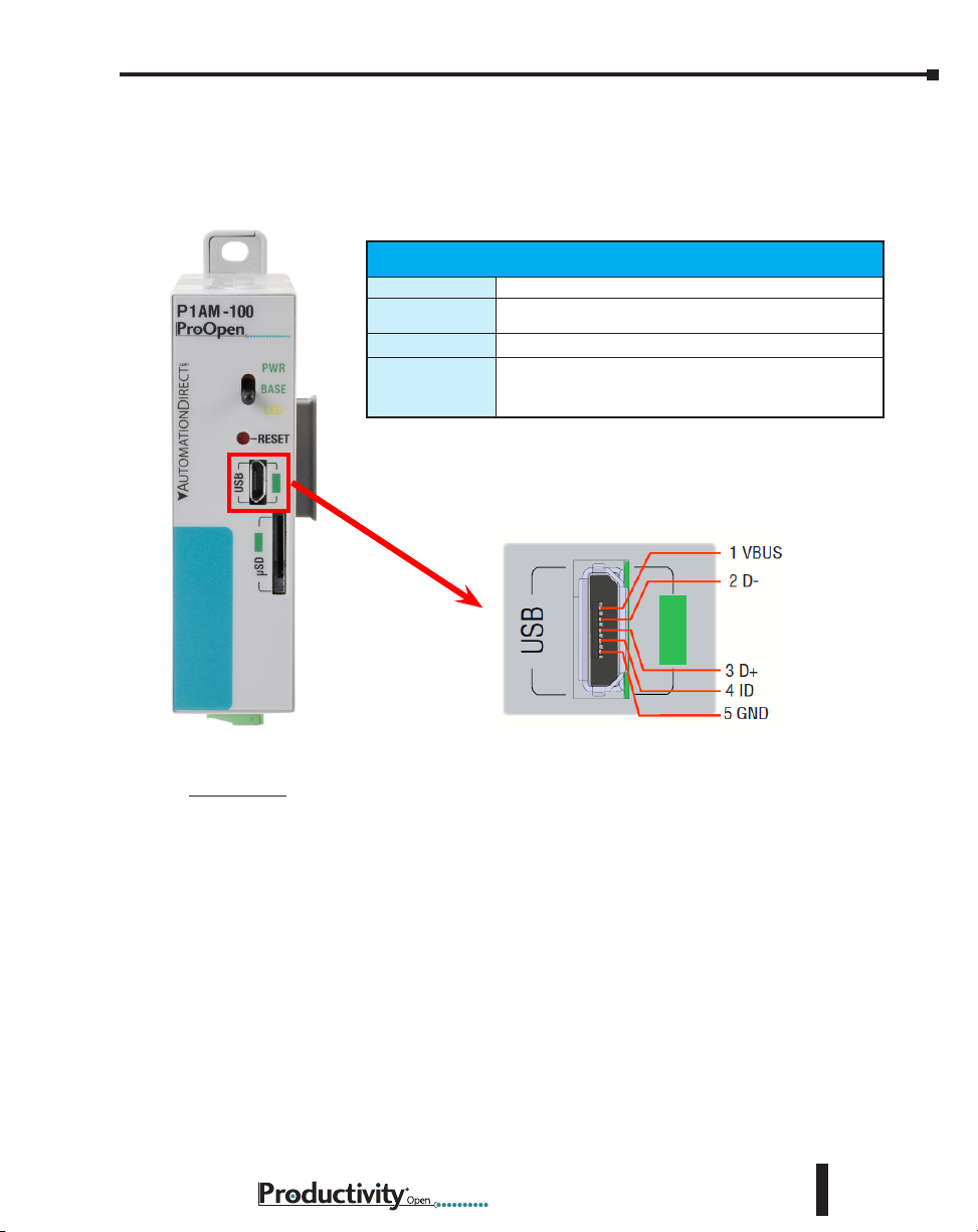
P1AM-100 MicroB USB Programming Port
The P1AM-100 controller has one built-in communication port; used exclusively for connecting
to a PC running the Arduino IDE programming software. Following are the specifications and
pin-out diagram.
Micro USB Type B Specications
Port Name
Description
Port Status LED
Cables
MicroB USB
Standard MicroB USB input for programming, monitoring,
and a power option
Green LED is illuminated when a power cable is plugged in.
USB Type A to Micro USB Type B:
6ft cable part # USB-CBL-AMICB6
15ft cable part # USB-CBL-AMICB15
P1AM-100
Hardware User Manual, 1st Ed. Rev. A
2–5
Page 25

Chapter 2: Specifications
PinSD
1
2
3
4
5
6
7
8
DAT2
CD/DAT3
CMD
VDD
CLK
VSS
DAT0
DAT1
microSD Slot
Retentive memory for data logging, parameter storage, etc. (Card not included with unit).
microSD Specications
Port Name
Description
Maximum Card
Capacity
Transfer Rate
(ADATA microSDHC
Class 4 memory card)
Port Status LED
microSD
Standard microSD socket for data logging
32GB
Mbps Minimum Typical Maximum
Read 14.3 14.4 14.6
Write 4.8 4.9 5.1
Green LED is illuminated when card is inserted and detected
1
8
Pin SD
1
DAT2
2
CD/DAT3
3
CMD
4
VDD
5
CLK
6
VSS
7
DAT0
8
DAT1
2–6
Hardware User Manual, 1st Ed. Rev. A
Page 26

Chapter 2: Specifications
P1AM-100 CPU Headers
Following are the specifications and pin-out diagram for the Arduino MKR-compatible
expansion bus available for Left Side Expansion Arduino MKR-compatible shields.
MKR Expansion Bus Pins
GPIO A0–A6, 0–14
Analog Input Pins A0–A6
P1AM-100
Analog Output
Pins
PWM Pins 0–8, 10, A3, A4
Interrupt Pins 0, 1, 4–8, A1, A2
5V 5V supply output
Vin 5V regulated supply
VCC 3.3 V supply output
GND Ground
RST Reset
AREF
Critical Notes:
Pins A3, A4, and 8–10 are used for the base
controller.
Do not exceed 46mA combined from pins 0, 1,
and 4–10.
Do not exceed 3.3 V on any I/O pin.
Do not exceed 7mA on any I/O pin.
Do not apply power to 5V or VCC
A0
Analog Input Reference
Hardware User Manual, 1st Ed. Rev. A
2–7
Page 27
Chapter 2: Specifications
Powering Your ProductivityOpen System
It is important to understand that the Productivity1000 I/O modules on the right side will be
powered either by the Productivity1000 power supply connected to the left of the CPU OR
by an external 24VDC power supply connected to the terminals at the bottom of the CPU
module. The ProductivityOpen shields sold by AutomationDirect will also be powered by
either of these sources.
NOTE: Only one of these 24VDC sources shall be connected.
Third party shields on the left side shall be powered in the field according to the manufacturer
specs.
The USB programming cable will power the CPU and shields connected on the left side of
the CPU.
CAUTION! Shields and I/O modules must not be connected or disconnected when power is applied.
Power Supply Options
LSX Shields
USB Power Cable
(5VDC)
ADC P1-01AC or
P1-02AC
AUX 24Vin
Open ADC ADC I/O
ø ø ø
ø ø ø
ø ø ø ø
CPU
RSX
2–8
MKR Header Power Limitations
Power Source 5V 3.3 V
USB 330mA 500mA 1.65 W
VIN (Pin Header) 600mA 1A 3.3 W
P1000 Series Supply
OR External 24V
850mA 1.28 A 4.25 W
Max. Combined
Power
Hardware User Manual, 1st Ed. Rev. A
Page 28

AutomationDirect Shields
Ethernet Communications Shield
The P1AM-ETH is a housed Arduino Compatible Ethernet Shield based on the Wiznet W5500
Ethernet Controller. It interfaces to the left side of the P1AM-100 CPU and most Arduino MKR
form factor shields.
Ethernet Features
• Supports Hardwired TCP Protocols:
TCP, UDP, ICMP, IPV4, ARP, IGMP, PPPOE
• Supports 8 independent sockets simultaneously
• Supports Power Down Mode
• Supports Wake on LAN over UDP
• Supports High Speed Serial Peripheral Interface (SPI MODE 0, 3)
• Internal 32K bytes of Memory for TX/RX Buffers
• 10BaseT / 100BaseTX Ethernet PHY embedded
• Supports Auto Negotiation (Full and Half Duplex,
10 and 100-based)
• Does Not Support IP Fragmentation
• 3.3 V operation with 5V I/O signal tolerance
• LED outputs (Full / Half duplex, Link, Speed, Active)
Chapter 2: Specifications
!WARNING!
Do not add or remove
modules with field power
applied!
General Specications
Operating Temperature
Storage Temperature
Humidity
Environmental Air
Vibration
Shock
Heat Dissipation
Enclosure Type
Power Budget
Recommended Library
Module Location
Weight
Agency Approvals
0° to 60°C (32° to 140°F)
-20° to 70°C (-4° to 158°F)
5 to 95% (non-condensing)
No corrosive gases permitted
IEC60068-2-6 (Test Fc)
IEC60068-2-27 (Test Ea)
750mW
Open Equipment
150mA/5V
Arduino Ethernet
Connects to the left side of the P1AM-100 CPU.
20g (0.8 oz.)
UL 61010-1 and
UL 61010-2-201 File E139594, Canada & USA
CE
Hardware User Manual, 1st Ed. Rev. A
2–9
Page 29
Chapter 2: Specifications
AutomationDirect Shields, cont’d
Header Pins Used for
Ethernet Shield
Pins Used Function
5
ETH SS
8
MOSI
SCK
MISO
SPI pins are shared
with other devices on
SPI bus
9
10
P1AM-ETH
MKR Expansion Bus Pins
GPIO A0–A6, 0–14
Analog Input Pins A0–A6
Analog Output
Pins
PWM Pins 0–8, 10, A3, A4
Interrupt Pins 0, 1, 4–8, A1, A2
5V 5V supply output
Vin 5V regulated supply
VCC 3.3 V supply output
GND Ground
RST Reset
AREF
Critical Notes:
Pins A3, A4, and 8–10 are used for the base controller.
Do not exceed 46mA combined from pins 0, 1, and 4–10.
Do not exceed 3.3 V on any I/O pin.
Do not exceed 7mA on any I/O pin.
Do not apply power to 5V or VCC
A0
Analog Input Reference
2–10
Hardware User Manual, 1st Ed. Rev. A
Page 30

AutomationDirect Shields, cont’d
Header Pin Breakout Module
The P1AM-GPIO is a housed Arduino MKR form factor shield that brings a subset of the MKR
header pins out to the front 18 position terminal block. These pins include basic overvoltage,
undervoltage, and overcurrent protection. It connects to the left side of the P1AM-100 CPU
and most Arduino MKR form factor shields.
General Specications
Operating Temperature
Storage Temperature
Humidity
Environmental Air
Vibration
Shock
Heat Dissipation
Enclosure Type
Module Location
Weight
Agency Approvals
Chapter 2: Specifications
0° to 60°C (32° to 140°F)
-20° to 70°C (-4° to 158°F)
5 to 95% (non-condensing)
No corrosive gases permitted
IEC60068-2-6 (Test Fc)
IEC60068-2-27 (Test Ea)
475mW
Open Equipment
Connects to the left side of the P1AM-100 CPU.
56g (2.0 oz.)
UL 61010-1 and
UL 61010-2-201 File E139594, Canada & USA
CE
!WARNING!
Do not add or remove
modules with field power
applied!
Terminal block connector sold separately.
Recommended connector options P2-RTB or
P2-RTB-1.
Hardware User Manual, 1st Ed. Rev. A
2–11
Page 31

Chapter 2: Specifications
AutomationDirect Shields, cont’d
P1AM-GPIO
MKR Expansion Bus Pins
GPIO A0–A6, 0–14
Analog Input Pins A0–A6
Analog Output
Pins
PWM Pins 0–8, 10, A3, A4
Interrupt Pins 0, 1, 4–8, A1, A2
5V 5V supply output
Vin 5V regulated supply
VCC 3.3 V supply output
GND Ground
RST Reset
AREF
Critical Notes:
Pins A3, A4, and 8–10 are used for the base
controller.
Do not exceed 46mA combined from pins 0,
1, and 4–10.
Do not exceed 3.3 V on any I/O pin.
Do not exceed 7mA on any I/O pin.
Do not apply power to 5V or VCC
A0
Analog Input Reference
Terminal Block Pins
Pin Functions
VCC 3.3 V supply output
DAC0*
A1 GPIO, Analog input, Interrupt
A2 GPIO, Analog input, Interrupt
A5 GPIO, Analog input
A6 GPIO, Analog input
0 GPIO, PWM, Interrupt
1 GPIO, PWM, Interrupt
2 GPIO, PWM
3 GPIO, PWM
4 GPIO, PWM, Interrupt
6 GPIO, PWM, Interrupt
7 GPIO, PWM, Interrupt
11 GPIO, SDA
12 GPIO, SCL
13 GPIO, RX
14 GPIO, TX
GND Ground
*There is no ESD, overvoltage, or overcurrent protection on the DAC0 pin.
GPIO, Analog input,
Analog output
2–12
Hardware User Manual, 1st Ed. Rev. A
Page 32
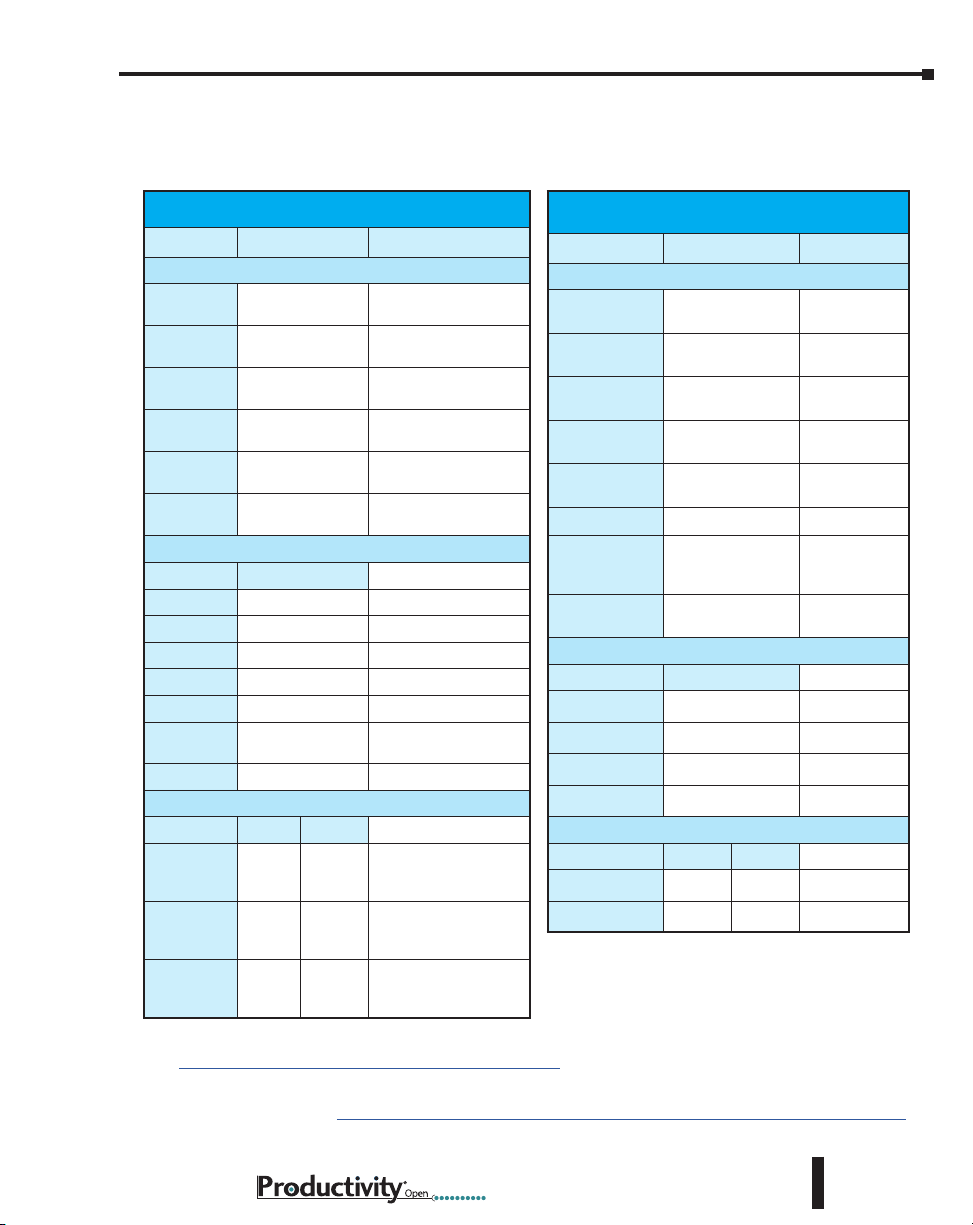
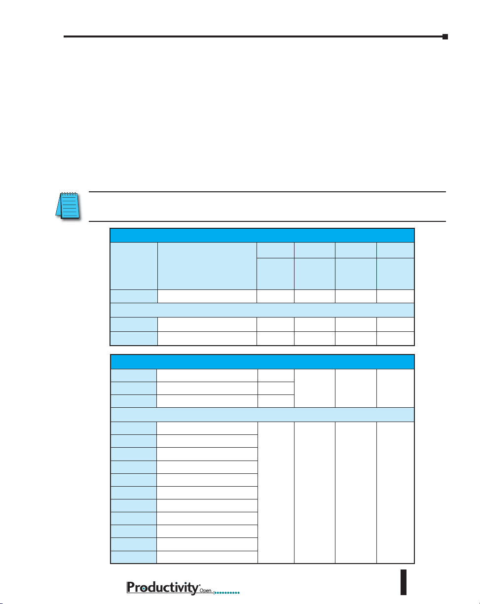
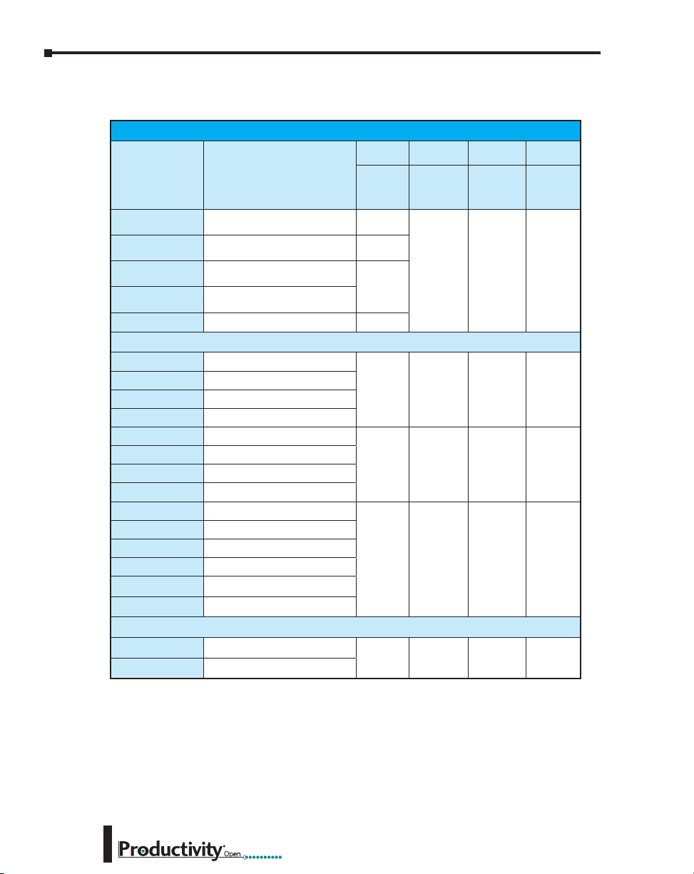
I/O Modules Overview
A variety of discrete and analog I/O modules from our Productivity1000 line are available
for use with the P1AM-100.
Chapter 2: Specifications
Productivity1000 Modules
Part Number Number of Inputs Description
Input Modules
P1-08SIM
P1-08ND3
P1-16ND3
P1-08NE3
P1-16NE3
P1-08NA
Output Modules
Number of Outputs
P1-08TD1
P1-08TD2
P1-15TD1
P1-15TD2
P1-08TA
P1-08TRS
P1-16TR
Input/Output Modules
Inputs Outputs
P1-15CDD1
P1-15CDD2
P1-16CDR
8 7
8 7
8 8
8
8
16
8
16
8
8 Sinking DC Output
8
15 Sinking DC Output
15
8
8
16
Input Simulator
Module
Sinking/Sourcing
12–24 VDC Input
Sinking/Sourcing
12–24 VDC Input
Sinking/Sourcing
24V AC/DC
Sinking/Sourcing
24V AC/DC
AC Isolated
100–240 VAC
Sourcing DC Output
Sourcing DC Output
AC Output
Isolated Relay
Output
Relay Output
Input: Sinking/
Sourcing; Output:
Sinking
Input: Sinking/
Sourcing; Output:
Sourcing
Input: Sinking/
Sourcing; Output:
Relay
Productivity1000 Modules
Part Number Number of Inputs Description
Input Modules
P1-04AD
P1-04ADL-1
P1-04ADL-2
P1-08ADL-1
P1-08ADL-2
P1-04RTD
P1-04THM
P1-04NTC
Output Modules
Number of Outputs
P1-04DAL-1
P1-04DAL-2
P1-08DAL-1
P1-08DAL-2
Input/Output Modules
P1-4ADL2DAL-1
P1-4ADL2DAL-2
4
4
4
8
8
4 RTD Input
4
4
4
4
8
8
Inputs Outputs
4 2
4 2
Analog Input
(Current)
Analog Input
(Current)
Analog Input
(Voltage)
Analog Input
(Current)
Analog Input
(Voltage)
Analog
Thermocouple
Input
Analog Thermistor
Input
Analog Output
(Current)
Analog Output
(Voltage)
Analog Output
(Current)
Analog Output
(Voltage)
Analog Input/Analog
Output (Current)
Analog Input/Analog
Output (Voltage)
Details on connecting to the Productivity1000 modules can be found at
https://github.com/facts-engineering/P1AM/wiki.
The Productivity1000 User Manual contains electrical and installation details. It is available for
FREE download at: https://cdn.automationdirect.com/static/manuals/p1userm/p1userm.html
Hardware User Manual, 1st Ed. Rev. A
2–13
Page 33

Chapter
Chapter
Chapter
InstallatIon and
IrIng
W
3
3
3
In This Chapter...
Safety Guidelines ....................................................................................................... 3–3
Plan for Safety .......................................................................................................... 3–3
Three Levels of Protection ........................................................................................3–4
Orderly System Shutdown ........................................................................................3–4
System Power Disconnect ........................................................................................3–4
Emergency Stop Circuits ..........................................................................................3–5
Introduction to the ProductivityOpen Mechanical Design ...................................... 3–6
Typical P1AM-100 ....................................................................................................3–6
Dimensions and Installation ...................................................................................... 3–7
Basic Dimensions .......................................................................................................3–9
Mounting Guidelines ............................................................................................... 3–12
Enclosures ..............................................................................................................3–12
Mounting Position ..................................................................................................3–12
Using Mounting Rails .............................................................................................3–12
Mounting Clearances .............................................................................................3–13
Temperature Considerations ................................................................................... 3–13
Power Considerations ............................................................................................. 3–13
Grounding .............................................................................................................3–14
Agency Approvals ...................................................................................................3–14
DIN Rail Mounting P1AM-100 System ....................................................................3–15
Surface Mounting P1AM-100 System ..................................................................... 3–15
Installing the I/O Modules ...................................................................................... 3–16
Wiring Guidelines ....................................................................................................3–17
Power Supply Wiring .............................................................................................. 3–17
Grounding .............................................................................................................3–17
Fuse Protection .......................................................................................................3–18
Page 34

Table of Contents
I/O Module Wiring Options ....................................................................................3–19
Hand Wiring System ............................................................................................... 3–19
ZIPLink Wiring System ...........................................................................................3–20
Terminal Block With Pigtail Cable ........................................................................... 3–20
Input and Output Modules ZIPLink Selections .......................................................3–21
Analog Modules ZIPLink Selections ........................................................................ 3–22
Removable Terminal Blocks (Optional) ................................................................... 3–23
P1-10RTB and P1-10RTB-1 .....................................................................................3–23
P2-RTB and P2-RTB-1 .............................................................................................3–23
Terminal Block Installation ...................................................................................... 3–24
Terminal Block Removal .......................................................................................... 3–25
Planning the I/O Wiring Routes .............................................................................. 3–25
System Wiring Strategies ........................................................................................3–26
CPU Isolation Boundaries .......................................................................................3–26
Sinking/Sourcing Concepts ....................................................................................3–27
I/O “Common Terminal” Concepts ........................................................................ 3–28
DC Input Wiring Methods ...................................................................................... 3–29
DC Output Wiring Methods ................................................................................... 3–29
Relay Outputs - Wiring Methods ............................................................................3–31
Relay Outputs – Transient Suppression for Inductive Loads in a Control System ..... 3–32
3–2
Hardware User Manual, 1st Ed. Rev. A
Page 35
Safety Guidelines
NOTE: Products with CE marks perform their required functions safely and adhere to relevant standards
as specified by CE directives provided they are used according to their intended purpose and that the
instructions in this manual are adhered to. The protection provided by the equipment may be impaired if
this equipment is used in a manner not specified in this manual. A listing of our international affiliates is
available on our Web site at http://www.automationdirect.com.
WARNING: Providing a safe operating environment for personnel and equipment is your responsibility
and should be your primary goal during system planning and installation. Automation systems can
fail and may result in situations that can cause serious injury to personnel or damage to equipment.
Do not rely on the automation system alone to provide a safe operating environment. You should
use external electromechanical devices, such as relays or limit switches, that are independent of the
P1AM-100 application to provide protection for any part of the system that may cause personal injury
or damage. Every automation application is different, so there may be special requirements for your
particular application. Make sure you follow all national, state, and local government requirements for
the proper installation and use of your equipment.
Plan for Safety
The best way to provide a safe operating environment is to make personnel and equipment
safety part of the planning process. You should examine every aspect of the system to determine
which areas are critical to operator or machine safety. If you are not familiar with controller
type system installation practices, or your company does not have established installation
guidelines, you should obtain additional information from the following sources.
• NEMA — The National Electrical Manufacturers Association, located in Washington,
D.C., publishes many different documents that discuss standards for industrial control
systems. You can order these publications directly from NEMA. Some of these include:
ICS 1, General Standards for Industrial Control and Systems
ICS 3, Industrial Systems
ICS 6, Enclosures for Industrial Control Systems
• NEC — The National Electrical Code provides regulations concerning the installation
and use of various types of electrical equipment. Copies of the NEC Handbook can
often be obtained from your local electrical equipment distributor or your local library.
• Local and State Agencies — many local governments and state governments have
additional requirements above and beyond those described in the NEC Handbook.
Check with your local Electrical Inspector or Fire Marshall office for information.
Chapter 3: Installation and Wiring
Hardware User Manual, 1st Ed. Rev. A
3–3
Page 36
Chapter 3: Installation and Wiring
Arm
Three Levels of Protection
WARNING: The control program must not be the only form of
protection for any problems that may result in a risk of personal
injury or equipment damage.
The publications mentioned provide many ideas and
requirements for system safety. At a minimum, you should
follow these regulations. Also, you should use the following
techniques, which provide three levels of system control.
1. Orderly system shutdown sequence in
the P1AM-100 control program.
2. Mechanical disconnect for output module power.
3. Emergency stop switch for
disconnecting system power.
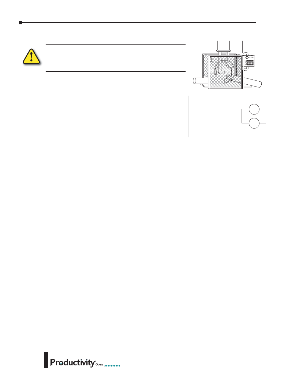
Orderly System Shutdown
The first level of fault detection is ideally the P1AM-100 control program, which can identify
machine problems. Certain shutdown sequences should be performed. These types of
problems are usually things such as jammed parts, etc., that do not pose a risk of personal
injury or equipment damage.
System Power Disconnect
You should also use electromechanical devices, such as master control relays and/or limit
switches, to prevent accidental equipment startup at an unexpected time. These devices should
be installed in a manner that will prevent any machine operations from occurring.
For example, if the machine in the illustration has a jammed part, the P1AM-100 control
program can turn off the saw blade and retract the arbor. If the operator must open the guard
to remove the part, you should also include a bypass switch that disconnects all system power
any time the guard is opened.
Jam
Detect
Turn off
Saw
RST
RST
Retract
3–4
Hardware User Manual, 1st Ed. Rev. A
Page 37
Chapter 3: Installation and Wiring
1
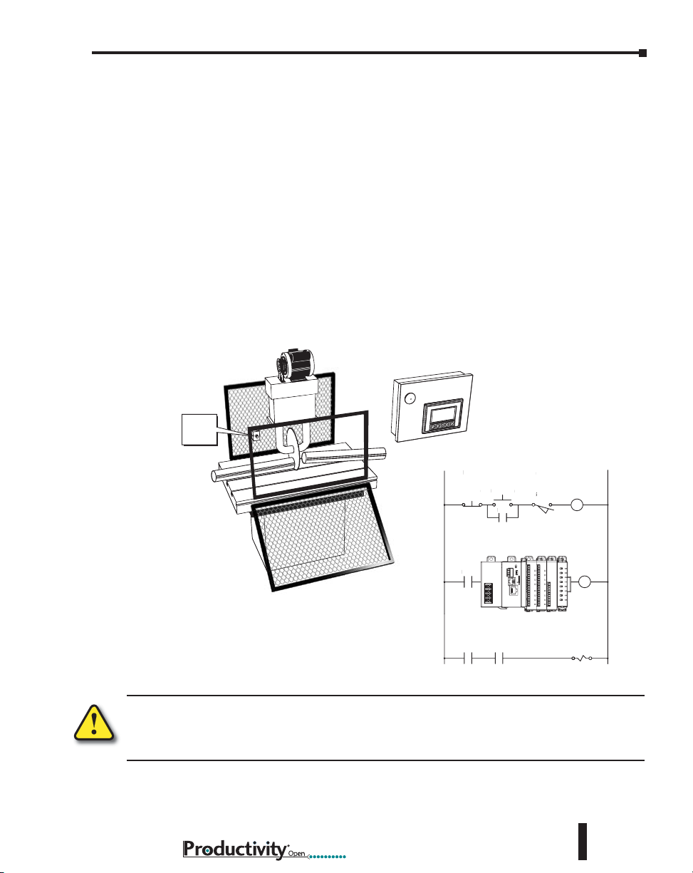
Emergency Stop Circuits
Emergency stop (E-Stop) circuits are a critical part of automation safety. For each machine
controlled by a P1AM-100, provide an emergency stop device that is wired outside the P1AM100 and easily accessed by the machine operator.
E-Stop devices are commonly wired through a master control relay (MCR) or a safety control
relay (SCR) that will remove power from the P1AM-100 I/O system in an emergency.
MCRs and SCRs provide a convenient means for removing power from the I/O system
during an emergency situation. By de-energizing an MCR (or SCR) coil, power to the input
(optional) and output devices is removed. This event occurs when any emergency stop switch
opens. However, the P1AM-100 continues to receive power and operate even though all its
inputs and outputs are disabled.
The MCR circuit could be extended by placing a P1AM-100 fault relay (closed during normal
P1AM-100 operation) in series with any other emergency stop conditions. This would cause
the MCR circuit to drop the P1AM-100 I/O power in case of a P1AM-100 failure (memory
error, I/O communications error, etc.).
EMERGENCY
STOP
Guard
Limit
Switch
L1 N
L
Use E-Stop and Master Control Relay
se E-Stop and Maste
E-Stop Power On
E-Stopower On
MCR
MCR
MCR
CR1
Limit
Switch
Master
Control
Relay (MCR)
CR1
Saw Arbor
WARNING: For some applications, field device power may still be present on the terminal block even
though the P1AM-100 is turned off. To minimize the risk of electrical shock, remove all field device
power before you expose or remove P1AM-100 wiring.
Hardware User Manual, 1st Ed. Rev. A
3–5
Page 38

Chapter 3: Installation and Wiring
Introduction to the ProductivityOpen Mechanical Design
The ProductivityOpen is a modular system built by adding Productivity1000 Input/output
modules and Arduino MKR-compatible shields to a P1AM-100 Arduino-compatible CPU.
The I/O modules are connected directly to the right side of the P1AM-100 and to each other
in a continuous stack up to 15 modules.
Power budget does need to be considered - 8 or fewer modules can use the P1-01AC,
exceeding 8 modules uses P1-02AC. No backplane or base is required. Each module
connection extends the backbone communication bus.
Connect Arduino-MKR shields to the left side of the P1AM-100 CPU. The combinations on
the left side are limited only by the general purpose IO pins that must be dedicated to each
shield.
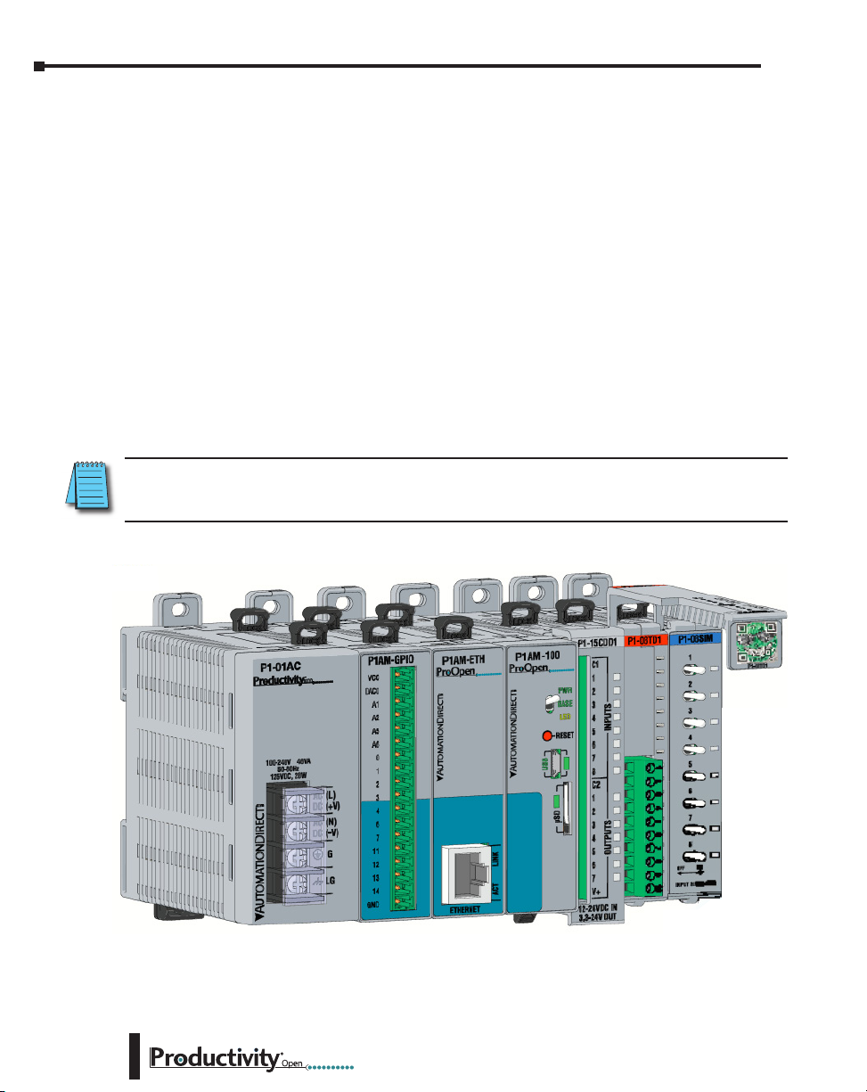
Typical P1AM-100
P1-08SIM
P1-08TD1
P1-15CDD1
C1
1
2
3
4
5
6
7
8
C2
1
2
3
4
5
6
7
V+
12-24VDC IN
3.3-24V OUT
INPUTSOUTPUTS
3.3-24VDC
SINK OUTPUT
COM
V+
1
2
3
4
5
6
7
8
1
2
3
4
5
6
7
8
OFF ON
INPUT SIMULATOR
P1-01AC
Power Supply
or Alternate
3–6
P1AM-PROTO
(Customizable
Shield Kit)
P1AM-GPIO
P1-15CDD1
Combo Module
P1AM-ETH
P1AM-100
Hardware User Manual, 1st Ed. Rev. A
P1-08TD1 Output
Module
P1-08SIM
Input Module
Page 39
Dimensions and Installation
Before installing the P1AM-100 you will need to know the dimensions of the components
considered. The tables and diagrams on the following pages provide basic dimensions to use
in defining your enclosure specifications. Remember to leave room for expansion module
insertion and/or replacement and for potential expansion. If you are using other components
in your system, refer to the appropriate manual to determine how those units can affect
mounting dimensions.
The basic dimensions for the modules are listed in the tables. The width varies depending on
the type of module. P1AM-100 is designed to be mounted on standard 35mm DIN rail, or it
may be surface mounted. Make sure you have followed the installation guidelines for proper
spacing.
NOTE: Dimensional drawings for the P1AM-100, power supplies, and all modules are available on the
AutomationDirect.com site.
Productivity Open Component Dimensions
Module
P1AM-100
P1AM-GPIO
P1AM-ETH
Description
Controller 23.1 [0.91] 77.0 [3.03] 92.8 [3.65] 91.3 [3.59]
Left Side Communication Shields (LSX)
General Purpose I/O
Ethernet Communication
Chapter 3: Installation and Wiring
A B C D
Height
w/Tabs
mm [in]
Depth
mm [in]
Width
mm [in]
23.1 [0.91] 77.0 [3.03] 92.8 [3.65] 86.7 [3.41]
23.1 [0.91] 77.0 [3.03] 92.8 [3.65] 89.7 [3.53]
Height
Faceplate
mm [in]
P1-01AC
P1-02AC
P1-01DC
P1-08SIM
P1-08ND3
P1-16ND3
P1-08NE3
P1-16NE3
P1-08NA
P1-08TD1
P1-08TD2
P1-15TD1
P1-15TD2
P1-08TA
Productivity1000 Component Dimensions
AC/DC Power Supply 35.0 [1.38]
AC Power Supply 52.2 [2.06]
DC Power Supply 35.0 [1.38]
Discrete Expansion Modules (Right Side)
Simulator Input
Sinking/Sourcing 12–24 VDC Input
Sinking/Sourcing 12–24 VDC Input
Sinking/Sourcing 12–24 VDC Input
Sinking/Sourcing 12–24 VDC Input
AC Isolated 100–240 VAC
Sinking Output
Sourcing Output
Sinking Output
Sourcing Output
AC Output
17.2 [0.68] 77.0 [3.03] 93.6 [3.69] 86.6 [3.41]
Hardware User Manual, 1st Ed. Rev. A
77.0 [3.03] 92.8 [3.65] 98.3 [3.87]
3–7
Page 40
Chapter 3: Installation and Wiring
Dimensions and Installation (continued)
ProductivityOpen Component Dimensions
A B C D
Module Description
P1-08TRS
Isolated Relay Output 17.2 [0.68]
Width
mm [in]
Height
Faceplate
mm [in]
mm [in]
Height
w/Tabs
Depth
mm [in]
P1-16TR
P1-15CDD1
P1-15CDD2
P1-16CDR
P1-04RTD
P1-04THM
P1-04NTC
P1-04AD
P1-04ADL-1
P1-04ADL-2
P1-04DAL-1
P1-04DAL-2
P1-08ADL-1
P1-08ADL-2
P1-08DAL-1
P1-08DAL-2
P1-4ADL2DAL-1
P1-4ADL2DAL-2
P1-02HSC
P1-04PWM
Relay Output 26.3 [1.03]
Input: Sinking/Sourcing;
Output: Sinking
Input: Sinking/Sourcing;
Output: Sourcing
Discrete Relay Combo Module 26.3 [1.03]
Analog Expansion Modules
Dierential RTD
Analog Thermocouple Input
Analog Thermistor Input
Analog Input (Current)
Analog Input (Current)
Analog Input (Voltage)
Analog Output (Current)
Analog Output (Voltage)
Analog Input (Current)
Analog Input (Voltage)
Analog Output (Current)
Analog Output (Voltage)
Analog Input/Analog Output (Current)
Analog Input/Analog Output (Voltage)
Specialty Expansion Modules
High-Speed Input (Current)
Pulse Width Modulation Input (Voltage)
77.0 [3.03] 93.6 [3.69] 86.6 [3.41]
17.2 [0.68]
17.2 [0.68] 77.0 [3.03] 93.6 [3.69] 81.6 [3.21]
17.2 [0.68] 77.0 [3.03] 93.6 [3.69] 81.9 [3.22]
17.2 [0.68] 77.0 [3.03] 93.6 [3.69] 81.6 [3.21]
17.2 [0.68] 77.0 [3.03] 93.6 [3.69] 81.6 [3.21]
3–8
Hardware User Manual, 1st Ed. Rev. A
Page 41
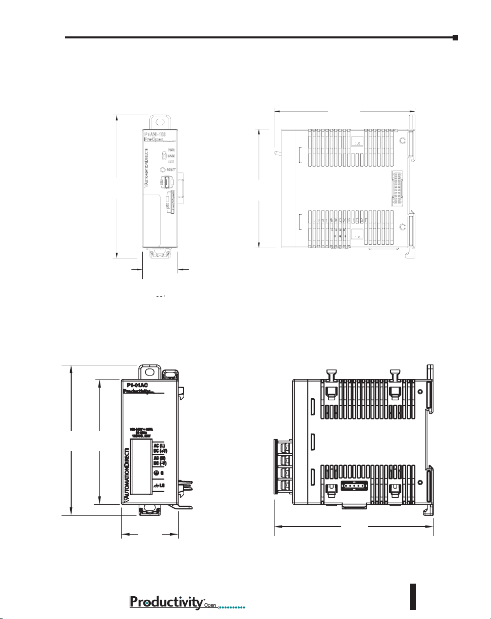
Basic Dimensions
P1AM-100
Chapter 3: Installation and Wiring
Units: mm [inches]
D
C
A
P1-01AC, P1-02AC and P1-01DC
C
B
B
A
Hardware User Manual, 1st Ed. Rev. A
D
3–9
Page 42

Chapter 3: Installation and Wiring
Basic Dimensions (continued)
Productivity1000 I/O Modules
P1AM-ETH
C
C
A
B
D
B
3–10
A
Hardware User Manual, 1st Ed. Rev. A
D
Units: mm [inches]
Page 43
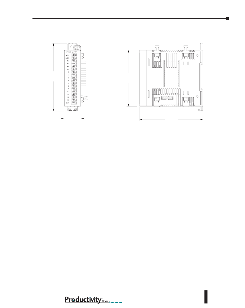
P1AM-GPIO Module
Chapter 3: Installation and Wiring
C
A
B
D
Units: mm [inches]
Hardware User Manual, 1st Ed. Rev. A
3–11
Page 44

Chapter 3: Installation and Wiring
Airflow
2ʺ
g
Mounting Guidelines
Enclosures
Your selection of a proper enclosure is important to ensure safe and proper operation of your
P1AM-100. Applications for the P1AM-100 vary and may require additional hardware
considerations. The minimum considerations for enclosures include:
• Conformance to electrical standards
• Protection from the elements in an industrial environment
• Common ground reference
• Maintenance of specified ambient temperature
• Access to the equipment
• Security or restricted access
• Sufficient space for proper installation and
maintenance of the equipment
Mounting Position
Mount the P1AM-100 and expansion modules horizontally, as shown in the illustration on the
following page, to provide proper ventilation. Do not mount vertically, upside down, or on a
flat horizontal surface.
NOTE: Add 2ʺ to mountin
depth when using ZIPLink
cable.
Using Mounting Rails
The ProductivityOpen modules can be secured within an enclosure or cabinet using mounting
rails. Use rails that conform to DIN EN standard 50022. We offer a complete line of DIN rail,
DINnectors and DIN rail mounted apparatus. The rails are approximately 35mm high, with a
depth of 7.5 mm. If you mount the module(s) on a DIN rail, consider using end brackets on
each side of the base. The end brackets keep the module(s) from sliding horizontally along the
rail, thus minimizing the possibility of accidentally pulling the wiring loose.
3–12
End Bracket (Part No. DN-EB35)
DIN Rail (Part No. DN-R35S1)
Hardware User Manual, 1st Ed. Rev. A
DIN Rail
Dimensions
7.5 mm
35 mm
Page 45

Chapter 3: Installation and Wiring
Mounting Clearances
Provide a minimum clearance of 2 inches (50mm) on all sides of the assembled system. Allow
extra clearance for door mounted operator panels, push buttons, lights and other items. There
should be a minimum of 3 inches (76mm) vertical clearance between the module(s) and any
wire duct, and a minimum of 7.2 inches (183mm) vertical distance from chassis to chassis in a
multiple unit installation.
The clearances required for P1AM-100 are represented in the graphic below of a similar PLC
system when mounted in an enclosure.
2”
50mm
min
7.2”
3”
min
3”
76mm
min
183mm
min
76mm
2”
50mm
min
Temperature Considerations
The P1AM-100 enclosure should be installed in an environment which is within the specified
equipment operating temperature. If the environment temperature deviates above or below the
specification, measures such as cooling or heating the enclosure should be taken to maintain
the specification.
Power Considerations
When the P1AM-100 is powered by a Productivity power supply (P1-01AC, P1-02AC or
P1-01DC), EMF/RFI line filters are not required to meet the requirements of the CE EMC
Directive.
Hardware User Manual, 1st Ed. Rev. A
3–13
Page 46

Chapter 3: Installation and Wiring
In addition to the panel layout guidelines, other specifications can affect the installation of a
CPU system. Always consider the following:
• Environmental Specifications
• Power Requirements
• Agency Approvals
• Enclosure Selection and Component Dimensions
Grounding
A sound common ground reference (earth ground) is essential for proper operation of the
P1AM-100. One side of all control circuits and power circuits along with the ground lead
must be properly connected to earth ground (earthing) either by connecting to the incoming
power system ground or by installing a ground rod in close proximity to the enclosure. There
must be a single-point ground (i.e. copper bus bar) for all devices in the enclosure that require
an earth ground.
Panel
Ground Braid
Copper Lugs
Panel or
Single Point
Ground
WARNING: Do not disconnect equipment unless power has been switched off.
Agency Approvals
Some applications require agency approvals for particular components. The ProductivityOpen
agency approvals are listed below:
3–14
Star Washers
Star Washers
• UL (Underwriters’ Laboratories, Inc.)
• CUL (Canadian Underwriters’ Laboratories, Inc.)
• CE (European Economic Union)
Hardware User Manual, 1st Ed. Rev. A
Page 47

Chapter 3: Installation and Wiring
DIN Rail Mounting P1AM-100 System
If you examine the module(s), you’ll notice retaining clips. To secure the module(s) to a
DIN rail, place the module(s) onto the rail and gently push up on the retaining clips. The
spring loaded clips lock the module onto the rail. To remove the module(s), pull down on the
retaining clips, slightly lift up the base, and pull it away from the rail.
This installation procedure applies to the P1AM-100, the P1AM-ETH and P1AM-GPIO
shields, and the Productivity1000 power supplies.
Step 1: Rotate unit upwards as you engage rear DIN
rail slot (image at right). Once engaged, rotate unit
downwards, firmly pressing into DIN rail. A noticeable
click affirms the unit is secure to DIN rail.
Step 2: Ensure all retaining clips are pushed up into
DIN rail.
Install end brackets on either side of unit to ensure unit
will not slide along the DIN rail.
Push up retaining
clips
Surface Mounting P1AM-100 System
The P1AM-100 system may be surface mounted as well. Extend the lower tabs for ease of
access. Use mounting holes in upper and lower tabs to secure the unit to panel surface.
Use Upper
Tab Slot
Use Extended
Lower Tab Slot
Hardware User Manual, 1st Ed. Rev. A
3–15
Page 48

Chapter 3: Installation and Wiring
Installing the I/O Modules
With latch in “locked” position, align
Step One:
connectors on the side of each module
and stack by pressing together. An
audible click indicates lock is engaged.
Step Two:
To unstack modules, pull locking latch up
into the unlocked position and then pull
modules apart.
WARNING: Do not connect, disconnect modules or
operate switches while circuit is live. P1AM-100 does
not support Hot Swapping!
3–16
Hardware User Manual, 1st Ed. Rev. A
Page 49
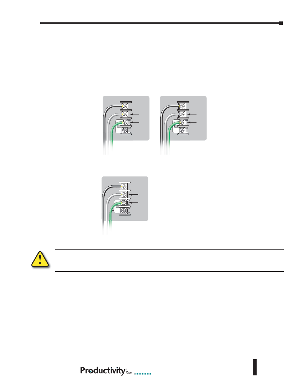
Wiring Guidelines
Power Hookup
P1-01AC
AC (L)
AC (N)
G
LG
100-240V 48VA
50-60Hz
125VDC, 20W
DC (+V)
DC (-V)
®
Power Hookup
P1-01AC
AC (L)
AC (N)
G
LG
100-240V 48VA
50-60Hz
125VDC, 20W
DC (+V)
DC (-V)
®
AC (L)
AC (N)
GND
LOGIC
GND
100–240 VAC
Power Supply Wiring
Connect the AC power source input wiring to the power supply as shown. The power supply
terminals can accept up to 14AWG solid or stranded wire. Do not over tighten the terminal
screws; the recommended torque is 7 to 9 inch-pounds (0.882 to 1.02 N·m).
P1-01AC and P1-02AC
Chapter 3: Installation and Wiring
125VDC 100–240 VAC
Grounding
+V
-V
GND
LOGIC
GND
AC (L)
AC (N)
GND
LOGIC
GND
P1-01DC
12–24 VDC
125VDC
+V
-V
GND
LOGIC
GND
WARNING: Once the power wiring is connected, secure the terminal block cover in the closed position.
When the cover is open there is a risk of electrical shock if you accidentally touch the connection
terminals or power wiring.
A good common ground reference (earth ground) is essential for proper operation of the
P1AM-100. One side of all control circuits and power circuits along with the ground lead
must be properly connected to earth ground by either installing a ground rod in close proximity
to the enclosure or by connecting to the incoming power system ground. There must be
a single-point ground (i.e. copper bus bar) for all devices in the enclosure that require an
earth ground.
Hardware User Manual, 1st Ed. Rev. A
3–17
Page 50
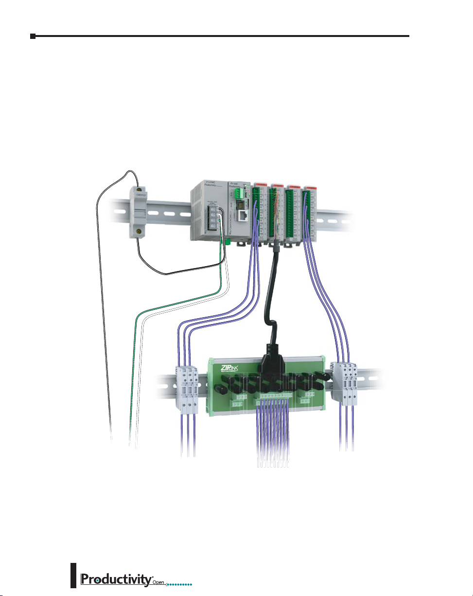
Chapter 3: Installation and Wiring
Fuse Protection
Some of the Input and Output I/O module circuits do not have internal fuses. In order to
protect your modules, we suggest you add external fuses to your I/O wiring. A fast-blow fuse
with a lower current rating than the I/O bank’s common current rating can be wired to each
common; or a fuse with a rating of slightly less than the maximum current per output point
can be added to each output. Refer to the I/O module specifications in Chapter 2 to find the
maximum current per output point or per output common. Adding the external fuse does not
guarantee the prevention of CPU damage, but it will provide added protection.
Fuse Block
Power Supply
Fused Common
3–18
Fuse
Blocks
ZIPLink Fuse
Module
Fuse
Blocks
Hardware User Manual, 1st Ed. Rev. A
Page 51
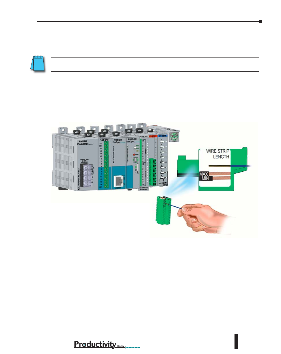
I/O Module Wiring Options
There are two available methods for wiring most I/O modules: hand wiring to the optional
removable I/O module terminal blocks or using the ZIPLink wiring system.
NOTE: Thermocouple, Thermistor, RTD, and HSC modules are not compatible with the ZIPLink system
and are shipped with fixed terminal blocks included.
Hand Wiring System
Field wiring may be attached using the removable terminal block connector. Use Wire Strip
Length reference on the terminal block as a guide when preparing wire for termination.
For easier assembly, wire may be connected to terminal block prior to installing block into
expansion module.
Chapter 3: Installation and Wiring
Hardware User Manual, 1st Ed. Rev. A
3–19
Page 52

Chapter 3: Installation and Wiring
I/O Module Wiring Options (continued)
ZIPLink Wiring System
The ZIPLink wiring system is the recommended method, which allows quick and easy
connection using cables that are prewired to the I/O module terminals at one end and plug into
a ZIPLink connector module terminal block at the other end. Use the tables on the following
pages to specify your ZIPLink wiring system.
ZIPLink Wiring
System
ZIPLink Pre-Wired Cables
Terminal Block With Pigtail Cable
For most I/O modules you can also purchase ZIPLink pigtail cables.
3–20
ZIPLink Module
ZIPLink Pigtail Cable
Hardware User Manual, 1st Ed. Rev. A
Page 53

Input and Output Modules ZIPLink Selections
Productivity1000 Input Module ZIPLink Selector
Input
Module
P1-08ND3
P1-16ND3
P1-08NE3
P1-16NE3
P1-08NA
Output
Module
P1-08TD1
P1-08TD2
P1-15TD1
P1-15TD2
P1-08TA
P1-08TRS
P1-16TR
I/O Module
# of Terms Component Module Part No. Cable Part No.
10
18 ZL-P1-CBL18*
10 ZL-P1-CBL10*
18 ZL-P1-CBL18*
10 ZL-P1-CBL10*
Feedthrough
Productivity1000 Output Module ZIPLink Selector
I/O Module
# of Terms Component Module Part No. Cable Part No.
10
18 ZL-P1-CBL18*
18 ZL-P1-CBL18*
10 ZL-P1-CBL10*
10 ZL-P1-CBL10*
18 ZL-P1-CBL18*
Feedthrough
ZIPLink
ZL-RTB20 or
ZL-RTB20-1
ZIPLink
ZL-RTB20 or
ZL-RTB20-1
Chapter 3: Installation and Wiring
ZL-P1-CBL10*
ZL-P1-CBL10*
Productivity1000 Combo Modules ZIPLink Selector
I/O Module
Output
Module
P1-15CDD1
P1-15CDD2
P1-16CDR
* Select the cable length by replacing the * with: Blank = 0.5 m, -1 = 1.0 m,
or -2 = 2.0 m.
# of Terms Component Module Part No. Cable Part No.
18 Feedthrough
ZIPLink
ZL-RTB20 or
ZL-RTB20-1
ZL-P1-CBL18*
Hardware User Manual, 1st Ed. Rev. A
3–21
Page 54
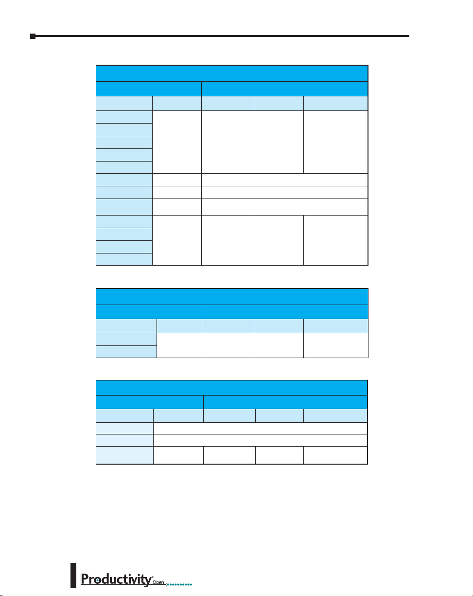
Chapter 3: Installation and Wiring
Analog Modules ZIPLink Selections
Productivity1000 Analog Module ZIPLink Selector
Module
Analog Module # of Terms Component Module Cable
P1-04AD
P1-04ADL-1
P1-04ADL-2
P1-08ADL-1
P1-08ADL-2
P1-04RTD
P1-04THM
P1-04NTC
P1-04DAL-1
P1-04DAL-2
P1-08DAL-1
P1-08DAL-2
10 Feedthrough
Matched Only See Note 1
T/C Wire Only See Note 1
Copper
Conductors
10 Feedthrough
See Note 1
ZIPLink
ZL-RTB20 or
ZL-RTB20-1
ZL-RTB20 or
ZL-RTB20-1
ZL-P1-CBL10*
ZL-P1-CBL10*
Productivity1000 Analog Combo Module ZIPLink Selector
Module
Analog Module # of Terms Component Module Cable
P1-4DAL2ADL-1
P1-4DAL2ADL-2
10 Feedthrough
ZIPLink
ZL-RTB20 or
ZL-RTB20-1
ZL-P1-CBL10*
3–22
Productivity1000 Specialty Modules ZIPLink Selector
See Note 1
See Note 1
ZL-RTB20 or
ZL-RTB20-1
ZIPLink
ZL-P1-CBL10*
Module
Input Module # of Terms Component Module Cable
P1-08SIM
P1-02HSC
P1-04PWM
* Select the cable length by replacing the * with: Blank = 0.5 m, -1 = 1.0 m, or -2 = 2.0 m.
1. These modules are not supported by the ZIPLink wiring system.
10
Feedthrough
Hardware User Manual, 1st Ed. Rev. A
Page 55
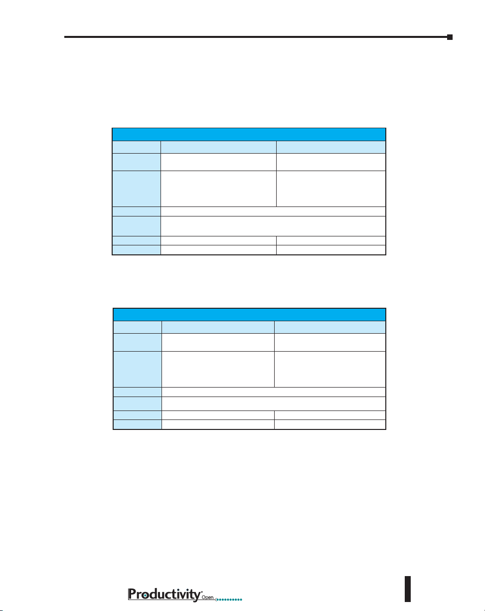
Chapter 3: Installation and Wiring
Removable Terminal Blocks (Optional)
The hand wiring method consists of purchasing the associated removable I/O module terminal
block (table below) and hand wiring from the I/O terminal block to a DIN rail mounted
terminal block.
P1-10RTB and P1-10RTB-1
Removable Terminal Block Specifications
Part Number P1-10RTB P1-10RTB-1
Number of
Positions
Wire Range
Conductors
Screw Driver
Screw Size
Screw Torque
* Recommended screw driver: P/N TW-SD-MSL-1.
10 Screw Terminals 10 Spring Clamp Terminals
30–16 AWG (0.051–1.31 mm²)
Solid / Stranded Conductor
3/64 in. (1.2 mm) Insulation Max.
1/4 in. (6–7 mm) Strip Length
“USE COPPER CONDUCTORS, 75°C” or Equivalent.
0.1 inch (2.5 mm) Maximum*
M2 N/A
2.5 lb·in (0.28 N·m) N/A
28–16 AWG (0.081–1.31 mm²)
Solid / Stranded Conductor
3/64 in. (1.2 mm) Insulation Max.
19/64 in. (7–8 mm) Strip Length
P2-RTB and P2-RTB-1
Removable Terminal Block Specifications
Part Number P2-RTB P2-RTB-1
Number of
Positions
Wire Range
Conductors
Screw Driver
Screw Size
Screw Torque
* Recommended screw driver: P/N TW-SD-MSL-1.
18 Screw Terminals 18 Spring Clamp Terminals
30–16 AWG (0.051–1.31 mm²)
Solid / Stranded Conductor
3/64 in. (1.2 mm) Insulation Max.
1/4 in. (6–7 mm) Strip Length
“USE COPPER CONDUCTORS, 75°C” or Equivalent.
0.1 inch (2.5 mm) Maximum*
M2 N/A
2.5 lb·in (0.28 N·m) N/A
28–16 AWG (0.081–1.31 mm²)
Solid / Stranded Conductor
3/64 in. (1.2 mm) Insulation Max.
19/64 in. (7–8 mm) Strip Length
Hardware User Manual, 1st Ed. Rev. A
3–23
Page 56
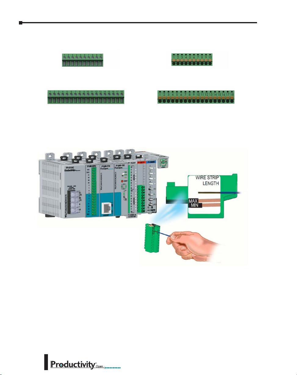
Chapter 3: Installation and Wiring
Removable Terminal Blocks, continued
P1-10RTB (screw terminals)
Removable Terminal Block
P2-RTB (screw terminals)
Removable Terminal Block
Terminal Block Installation
P1-10RTB-1 (spring-clip terminals)
Removable Terminal Block
P2-RTB-1 (spring-clip terminals)
Removable Terminal Block
3–24
Use the Wire Strip Length gauge printed on the end of the terminal strip as a guide to properly
strip wire insulation prior to inserting into terminal block. For ease of assembly, block maybe
wired prior to installation, if desired.
Insert terminal block as follows:
Step 1: Raise finger-safe terminal guard.
Step 2: Align terminal block with module terminal pins, ensuring correct orientation of
block.
Step 3: Firmly and evenly press terminal block onto terminal pins until seated. Lower finger-
safe guard into place.
Hardware User Manual, 1st Ed. Rev. A
Page 57

Chapter 3: Installation and Wiring
Terminal Block Removal
WARNING: Ensure local and remote power supplies have been disconnected prior to removing terminal
block.
Remove terminal block as follows:
Step 1: Raise terminal cover.
Step 2: Pull terminal block release lever forward.
This will lift terminal block away from
pins.
Step 2: Grasp block firmly and pull away from
module.
Terminal Release Lever
Planning the I/O Wiring Routes
The following guidelines provide general information on how to wire the I/O connections to
Productivity1000 modules. For specific information on wiring a particular I/O module refer
to the module specifications in Chapter 2.
1. If using removable terminal blocks, follow the wire size guidelines
in the I/O modules specifications in Chapter 2.
2. Always use a continuous length of wire. Do not splice wires to create a needed length.
3. Use the shortest possible wire length.
4. Use wire trays for routing where possible.
5. Avoid running low voltage control wires near high voltage wiring.
6. Avoid confusion by laying input wiring separate from output wiring where possible.
7. To minimize voltage drops when wires must run a long distance,
consider using multiple wires for the return line.
8. Avoid running DC wiring in close proximity to AC wiring where possible.
9. Avoid creating sharp bends in the wires; follow accepted Electrical Code standards.
Terminal Cover
Hardware User Manual, 1st Ed. Rev. A
3–25
Page 58

Chapter 3: Installation and Wiring
System Wiring Strategies
The P1AM-100 is very flexible and will work in many different wiring configurations. By
studying this section before actual installation, you may find the best wiring strategy for your
application. This will help to lower system cost and wiring errors, and avoid safety problems.
CPU Isolation Boundaries
CPU circuitry is divided into three main regions separated by isolation boundaries, shown
in the drawing below. Electrical isolation provides safety, so that a fault in one area does not
damage another. The transformer in the power supply provides magnetic isolation between
the primary and secondary sides. Optical isolators provide isolation in Input and Output
circuits. This isolates logic circuitry from the field side, where factory machinery connects.
The discrete inputs are isolated from the discrete outputs because each is isolated from the
logic side. Isolation boundaries protect the devices which are connected to the communication
ports, such as PCs and HMIs, from power input faults or field wiring faults. When wiring a
controller, it is extremely important to avoid making external connections that connect logic
side circuits to any other.
Power
Input
Power Supply
communication devices
24VDC
Input/
Output
Circuit
Isolation Boundary
HMI or other
Com
Ports
ControllerShieldShield
Logic Circuit
PC
Com
Ports
Maximum 15 I/O Modules
Output ModuleInput Module
Logic
Circuit
Input
Circuit
Logic
Circuit
Output
Circuit
3–26
Hardware User Manual, 1st Ed. Rev. A
Page 59
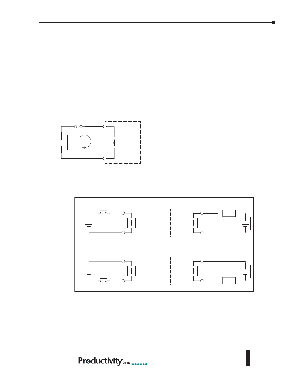
Chapter 3: Installation and Wiring
Sinking/Sourcing Concepts
Before wiring field devices to the CPU I/O, it’s necessary to have a basic understanding of
“sinking” and “sourcing” concepts. Use of these terms occurs frequently in input or output
circuit discussions. These terms only apply to DC circuits, not AC circuits. The purpose of
this section is to explain the terms. The short definitions are as follows:
• Sinking = Path to supply ground (–) or switching ground.
• Sourcing = Path to supply source (+) or switching +V.
Input and output points that are either sinking or sourcing can conduct current in only one
direction. This means it is possible to wire the external supply and field device to the I/O
point with current trying to flow in the wrong direction, in which case the circuit will not
operate.
Input
(sinking)
+
–
Common
CPU
Input
Sensing
of the arrow when the switch is closed. By applying the circuit principle above to the four
possible combinations of input/output sinking/sourcing types, we have the four circuits as
shown below.
The diagram on the left shows a “sinking” CPU input.
To properly connect the external supply, connect it so
that the input provides a path to ground (–). Start
at the CPU input terminal, follow through the input
sensing circuit, exit at the common terminal, and
connect the supply (–) to the common terminal.
The switch between the supply (+) and the input
completes the circuit. Current flows in the direction
Sinking Input Sinking Output
Input
+
–
Sourcing Input Sourcing Output
+
–
Common
Common
Input
CPU
Input
Sensing
CPU
Input
Sensing
Output
Switch
Output
Switch
CPU
CPU
Hardware User Manual, 1st Ed. Rev. A
Output
Common
Common
Output
Load
Load
+
–
+
–
3–27
Page 60

Chapter 3: Installation and Wiring
I/O “Common Terminal” Concepts
In order for a CPU I/O circuit to operate, current must enter at one terminal and exit at
another. This means at least two terminals are associated with every I/O point. In the figure
below, the input or output terminal is the main path for the current. One additional terminal
must provide the return path to the power supply.
If there was unlimited module space then every I/O point could have two dedicated terminals
as the figure above shows. Providing this level of flexibility is not practical or necessary for
most applications. Most I/O point groups share the return path (common) among two or
more I/O points. The figure below shows a group (or bank) of four input points which share a
common return path. In this way, the four inputs require only five terminals instead of eight.
Field
Device
+
–
Main Path
(I/O point)
Return Path
Input 1
CPU
Input Sensing
CPU
I/O
Circuit
3–28
Input 2
Input 3
Input 4
+
–
Electrical Common
To All Input Points
Common
NOTE: In the circuit above, the current in the common path is equal to the sum of the energized channels.
This is especially important in output circuits, where larger gauge wire is sometimes needed for the
commons.
Hardware User Manual, 1st Ed. Rev. A
Page 61

Chapter 3: Installation and Wiring
CPU DC Input
Field Device
CPU DC Input
DC Input Wiring Methods
I/O modules with DC inputs can be wired as either sinking or
Input
Common
Sinking Input Sensor (NPN Type) to CPU Sourcing Input
In the following example, a field device has an open-collector NPN transistor output. When
energized, it sinks current to ground from the DC input point. The CPU input current is
sourced from the common terminal connected to power supply (+).
sourcing inputs. The dual diodes (shown in this diagram) allow
current to flow in either direction. Inputs grouped by a common
point must be either all sinking or all sourcing. DC inputs typically
operate in the range of +12–24 VDC.
DC NPN Sensor
(Sinking)
Sourcing Input Sensor (PNP Type) to CPU Sinking Input
In the following example, a field device has an open-emitter PNP transistor output. When
energized, it sources current to the CPU input point, which sinks the current to ground. Since
the field device loop is sourcing current, no additional power supply is required for the module.
DC PNP Sensor
(Sourcing)
DC Output Wiring Methods
I/O modules with DC output circuits are wired as all current sinking only or current sourcing
only depending on which output module part number is used. DC outputs typically operate
in the range of +5–24 VDC.
CPU Sinking Output to Sourcing Load Device
Many applications require connecting a CPU output point to a DC input on a field device load.
This type of connection is made to carry a low-level DC signals.
In the following example, the CPU output point sinks current to ground (common) when
energized. The output is connected to a field device load with a sourcing input.
CPU Output
(Sinking)
Field Device
+DC Power
+
–
+
20-28 VDC
Input
(sourcing)
Input
(sinking)
Output
(sinking)
Supply
Ground Common
Output (sourcing)
Ground Common
Power
Output
(sinking)
Common
–
Input
(sourcing)
Ground
CPU Input
(Sourcing)
CPU Input
(Sinking)
Field DeviceCPU DC Output
DC Load
(Sourcing)
Hardware User Manual, 1st Ed. Rev. A
3–29
Page 62
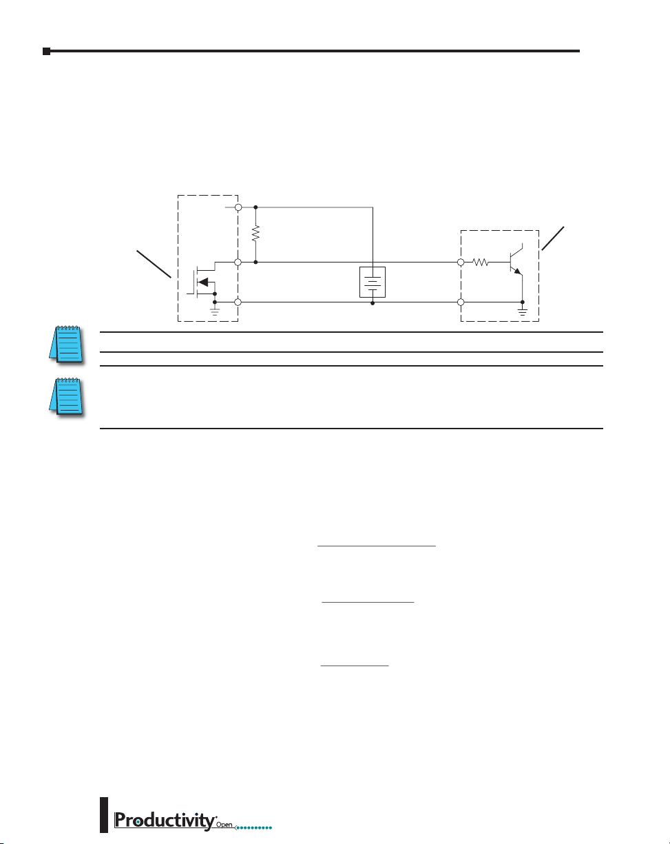
Chapter 3: Installation and Wiring
CPU DC Output
V
pull-up
CPU DC Sinking Output to Sinking Load Device
In the example below, a sinking output point is connected to the sinking input of a field device
load. In this case, both the CPU output and field device input are sinking type. Since the
circuit must have one sourcing and one sinking device, we add sourcing capability to the CPU
output by using a pull-up resistor. In the circuit below, we connect R pull-up from the output
to the DC output circuit power input.
Common
pull-up
I
input
R
pull-up
Power
R
pull-up
(sourcing)
Output
properly.
=
=
Supply
V
input
R
supply
DC NPN Load
Field Device
R
Input
+
–
pull-up
(sinking)
Ground
. In order to do so, we need to know the
input
(Sinking)
) when the input is energized. If this value
. Then calculate the power P
pull-up
input (turn–on)
input
– 0.7
I
input
R
–
input
input
pull-up
and
(in
CPU Output
(Sinking with
Pull-up Resistor)
NOTE: DO NOT attempt to drive a heavy load (>25mA) with this pull-up method.
NOTE: Using the pull-up resistor to implement a sourcing output has the effect of inverting the output
point logic. In other words, the field device input is energized when the CPU output is OFF, from a ladder
logic point-of-view. Your ladder program must comprehend this and generate an inverted output. Or, you
may choose to cancel the effect of the inversion elsewhere, such as in the field device.
+DC pwr
(sinking)
It is important to choose the correct value of R
nominal input current to the field device (I
is not known, it can be calculated as shown (a typical value is 15mA). Then use I
the voltage of the external supply to compute R
watts), in order to size R
3–30
P
pull-up
V
=
R
supply
2
Hardware User Manual, 1st Ed. Rev. A
Page 63

Chapter 3: Installation and Wiring
Relay with Form A contacts
Relay Outputs - Wiring Methods
Relay outputs are available for the ProductivityOpen. Relays are best for the following
applications:
• Loads that require higher currents than the solid-state outputs can deliver
• Cost-sensitive applications
• Some output channels need isolation from other outputs (such as when some loads
require different voltages than other loads)
Some applications in which NOT to use relays:
• Loads that require currents under 10mA
• Loads which must be switched at high speed or heavy duty cycle.
Relay outputs are available in two contact arrangements. Form
A type, or SPST (single pole, single throw) type. They are
normally open and are the simplest to use. The Form C, or
SPDT (single pole, double throw) type has a center contact
which moves and a stationary contact on either side. This
provides a normally closed contact and a normally open contact.
Relay with Form C contacts
The relays in some relay output modules share common
terminals, which connect to the wiper contact in each relay of
the bank. Other relay modules have relays which are completely
isolated from each other. In all cases, the module drives the
relay coil when the corresponding output point is on.
Hardware User Manual, 1st Ed. Rev. A
3–31
Page 64
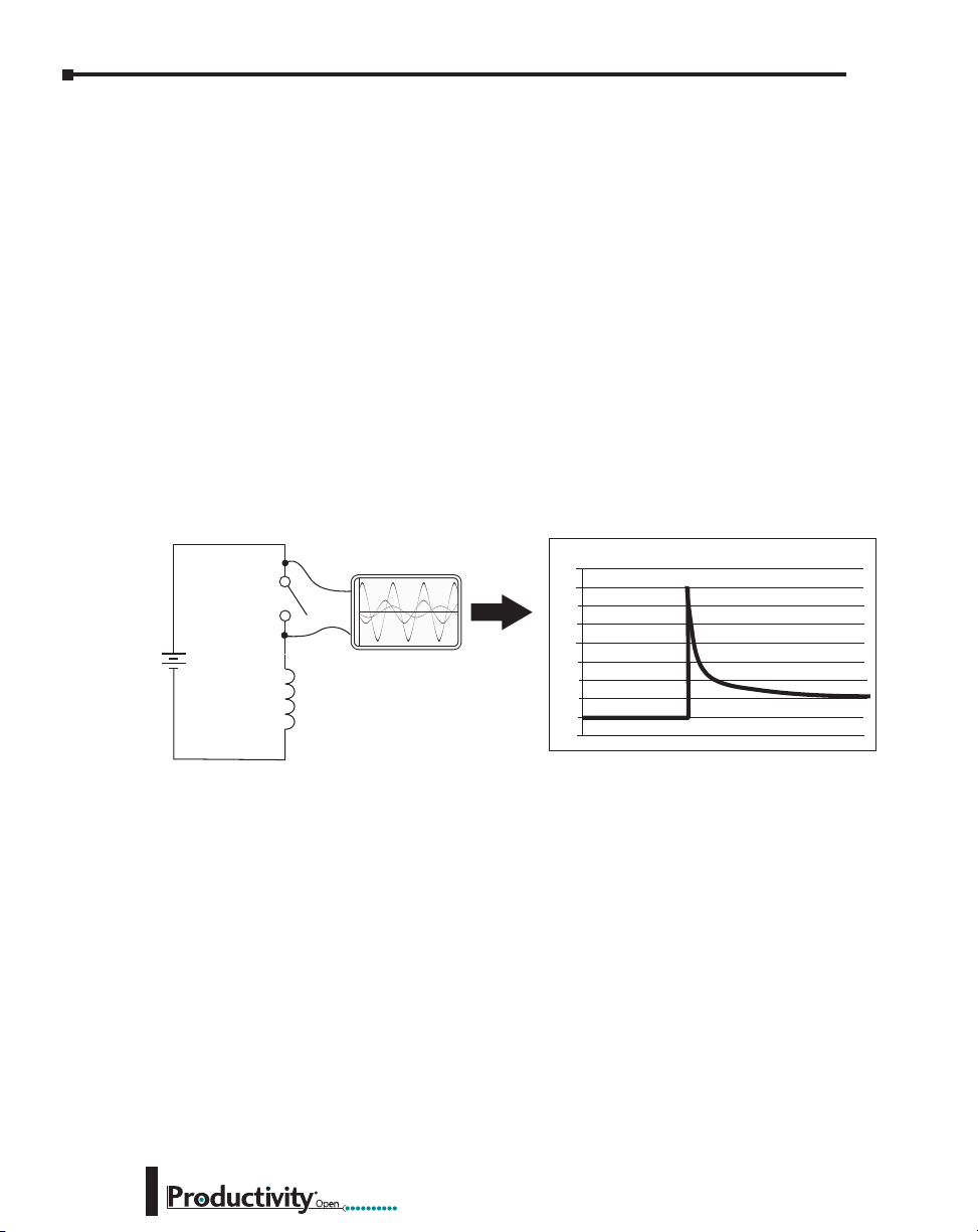
Chapter 3: Installation and Wiring
Relay Outputs – Transient Suppression for Inductive Loads in a Control System
The following pages are intended to give a quick overview of the negative effects of transient
voltages on a control system and provide some simple advice on how to effectively minimize
them. The need for transient suppression is often not apparent to the newcomers in the
automation world. Many mysterious errors that can afflict an installation can be traced back
to a lack of transient suppression.
What is a Transient Voltage and Why is it Bad?
Inductive loads (devices with a coil) generate transient voltages as they transition from being
energized to being de-energized. If not suppressed, the transient can be many times greater
than the voltage applied to the coil. These transient voltages can damage CPU outputs or other
electronic devices connected to the circuit, and cause unreliable operation of other electronics
in the general area. Transients must be managed with suppressors for long component life and
reliable operation of the control system.
This example shows a simple circuit with a small 24V/125mA/3W relay. As you can see, when
the switch is opened, thereby de-energizing the coil, the transient voltage generated across the
switch contacts peaks at 140V.
Example: Circuit with no Suppression
Volts
160
140
120
100
80
60
40
20
0
-20
24 VDC
Oscilloscope
+
-
Relay Coil
(24V/125mA/3W,
AutomationDirect part no.
750R-2C-24D)
3–32
In the same circuit, replacing the relay with a larger 24V/290mA/7W relay will generate a
transient voltage exceeding 800V (not shown). Transient voltages like this can cause many
problems, including:
• Relay contacts driving the coil may experience arcing, which can pit the contacts and
reduce the relay’s lifespan.
• Solid state (transistor) outputs driving the coil can be damaged if the transient voltage
exceeds the transistor’s ratings. In extreme cases, complete failure of the output can
occur the very first time a coil is de-energized.
• Input circuits, which might be connected to monitor the coil or the output driver, can
also be damaged by the transient voltage.
A very destructive side-effect of the arcing across relay contacts is the electromagnetic
interference (EMI) it can cause. This occurs because the arcing causes a current surge, which
releases RF energy. The entire length of wire between the relay contacts, the coil, and the
power source carries the current surge and becomes an antenna that radiates the RF energy. It
will readily couple into parallel wiring and may disrupt the CPU and other electronics in the
area. This EMI can make an otherwise stable control system behave unpredictably at times.
Hardware User Manual, 1st Ed. Rev. A
Page 65

Chapter 3: Installation and Wiring
Oscilloscope
Oscilloscope
CPU’s Integrated Transient Suppressors
Although the CPU outputs typically have integrated suppressors to protect against transients,
they are not capable of handling them all. It is usually necessary to have some additional
transient suppression for an inductive load.
Here is another example using the same 24V/125mA/3W relay used earlier. This example
measures the PNP transistor output of a typical CPU, which incorporates an integrated Zener
diode for transient suppression. Instead of the 140V peak in the first example, the transient
voltage here is limited to about 40V by the Zener diode. While the CPU will probably tolerate
repeated transients in this range for some time, the 40V is still beyond the module’s peak
output voltage rating of 30V.
Example: Small Inductive Load with Only Integrated Suppression
Volts
45
40
35
30
25
20
15
10
5
0
-5
VDC
* For this example, a 24V/125mA/3W
relay is used (AutomationDirect
part no. 750R-2C-24D)
24
Relay
Coil*
The next example uses the same circuit as above, but with a larger 24V/290mA/7W relay,
thereby creating a larger inductive load. As you can see, the transient voltage generated is much
worse, peaking at over 50V. Driving an inductive load of this size without additional transient
suppression is very likely to permanently damage the CPU output.
Example: Larger Inductive Load with Only Integrated Suppression
Volts
60
50
40
30
20
10
0
-10
��
9' &
Relay
Coil*
* For this example, a 24/290mA/7W
relay is used (AutomationDirect
part no. SC-E03G-24VDC)
Additional transient suppression should be used in both of these examples. If you are unable
to measure the transients generated by the connected loads of your control system, using
additional transient suppression on all inductive loads would be the safest practice.
Hardware User Manual, 1st Ed. Rev. A
3–33
Page 66
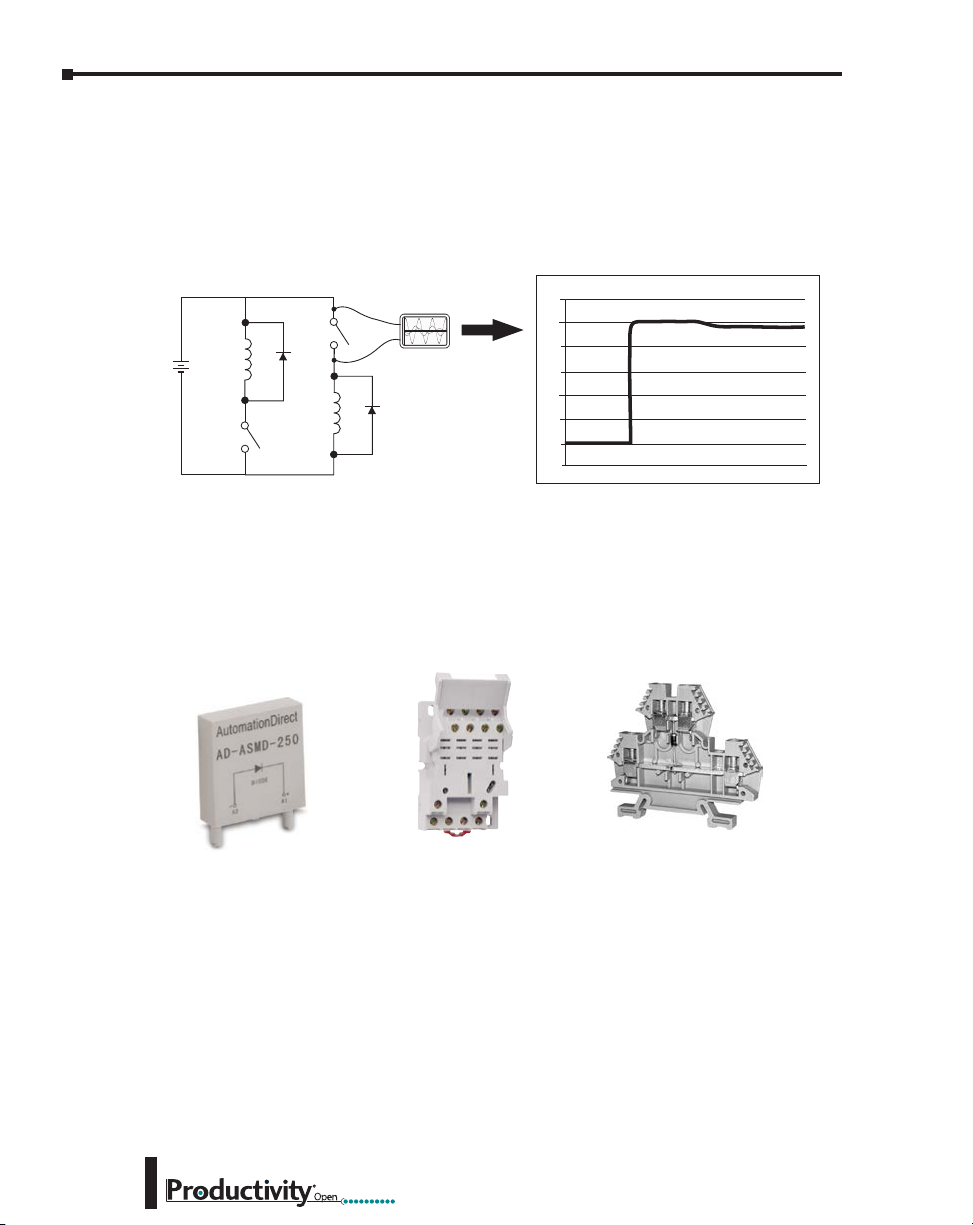
Chapter 3: Installation and Wiring
Sinking
Types of Additional Transient Protection
DC Coils:
The most effective protection against transients from a DC coil is a flyback diode. A flyback
diode can reduce the transient to roughly 1V over the supply voltage, as shown in this example.
24 VDC
DC Flyback Circuit
Oscilloscope
+
_
Sourcing
Volts
30
25
20
15
10
5
0
-5
Many AutomationDirect socketed relays and motor starters have add-on flyback diodes
that plug or screw into the base, such as the AD-ASMD-250 protection diode module and
784-4C-SKT-1 socket module shown below. If an add-on flyback diode is not available for
your inductive load, an easy way to add one is to use AutomationDirect’s DN-D10DR-A
diode terminal block, a 600VDC power diode mounted in a slim DIN rail housing.
3–34
AD-ASMD-250
Protection Diode Module
784-4C-SKT-1
Relay Socket
DN-D10DR-A
Diode Terminal Block
Hardware User Manual, 1st Ed. Rev. A
Page 67
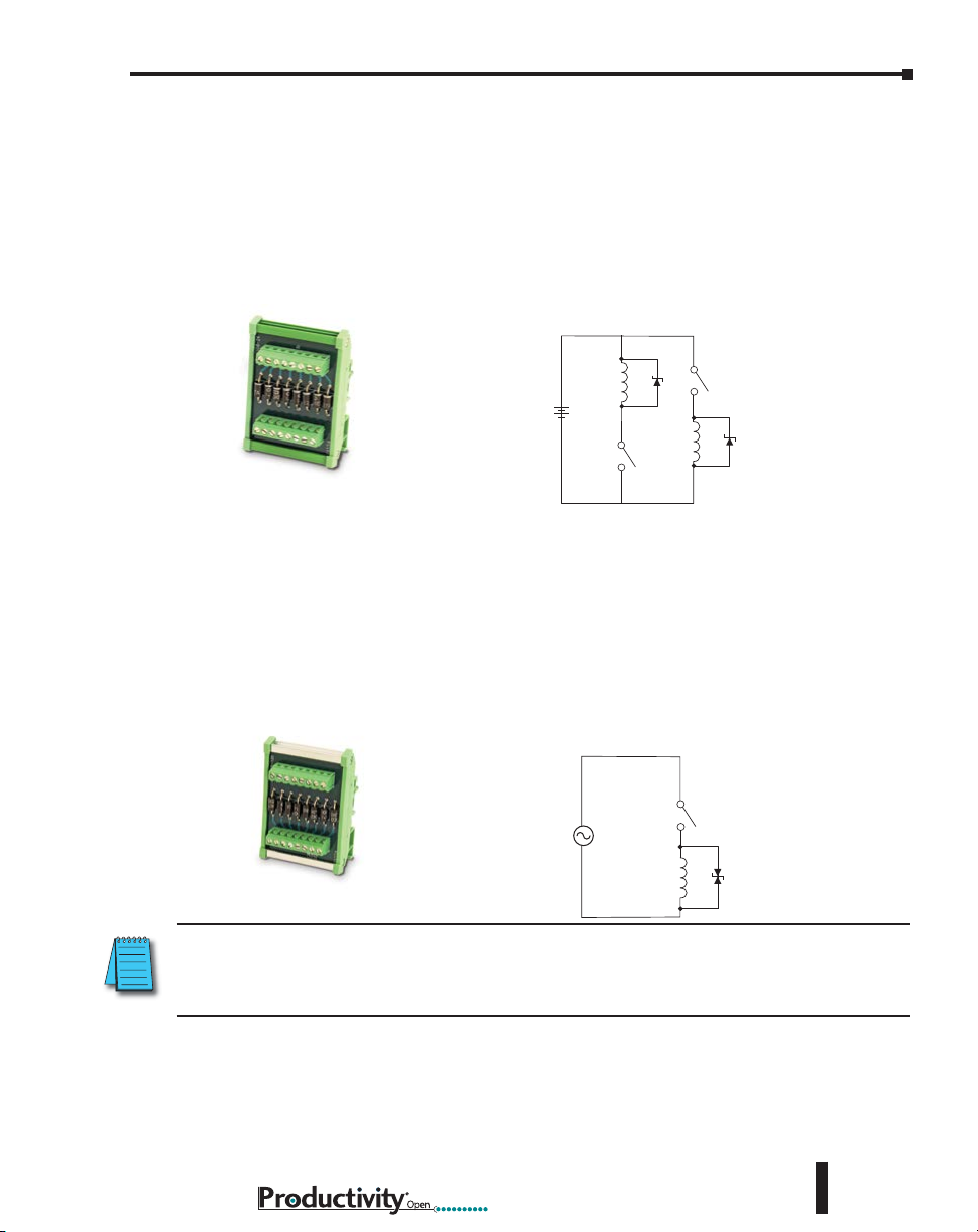
Chapter 3: Installation and Wiring
DC MOV or TVS Diode Circuit
Sinking
Sourcing
A
Two more common options for DC coils are Metal Oxide Varistors (MOV) or TVS diodes.
These devices should be connected across the driver (CPU output) for best protection as shown
below. The optimum voltage rating for the suppressor is the lowest rated voltage available that
will NOT conduct at the supply voltage, while allowing a safe margin.
AutomationDirect’s ZL-TSD8-24 transorb module is a good choice for 24VDC circuits. It
has a bank of 8 uni-directional 30V TVS diodes. Since they are uni-directional, be sure to
observe the polarity during installation. MOVs or bi-directional TVS diodes would install at
the same location, but have no polarity concerns.
+
24 VDC
_
ZL-TSD8-24
Transorb Module
AC Coils:
Two options for AC coils are MOVs or bi-directional TVS diodes. These devices are most
effective at protecting the driver from a transient voltage when connected across the driver
(CPU output) but are also commonly connected across the coil. The optimum voltage rating
for the suppressor is the lowest rated voltage available that will NOT conduct at the supply
voltage, while allowing a safe margin.
AutomationDirect’s ZL-TSD8-120 transorb module is a good choice for 120VAC circuits. It
is a bank of eight bi-directional 180V TVS diodes.
C MOV or Bi-Directional Diode Circuit
VAC
ZL-TSD8-120
Transorb Module
NOTE: Manufacturers of devices with coils frequently offer MOV or TVS diode suppressors as an addon option which mount conveniently across the coil. Before using them, carefully check the suppressor
ratings. Just because the suppressor is made specifically for that part does not mean it will reduce the
transient voltages to an acceptable level.
For example, a MOV or TVS diode rated for use on 24-48 VDC coils would need to have a
high enough voltage rating to NOT conduct at 48V. That suppressor might typically start
conducting at roughly 60VDC. If it were mounted across a 24V coil, transients of roughly
84V (if sinking output) or -60V (if sourcing output) could reach the CPU output. Many
semiconductor CPU outputs cannot tolerate such levels.
Hardware User Manual, 1st Ed. Rev. A
3–35
Page 68

Security
conSiderationS for
control SyStemS
Appendix
Appendix
Appendix
networkS
In This Appendix...
Security Considerations for Controls Networks .......................................................1–2
A
A
A
Page 69

Appendix A: Security Considerations for Control Systems Networks
Security Considerations for Control Systems Networks
Manufacturers are realizing that to stay competitive, their Automation and Control Systems
need to be more integrated within their plant. The systems often need to be integrated with
upstream Enterprise Data Systems, and even further integrated to allow information to be
accessible across multiple plants, or even through the Internet. This convergence of the IT
world with the Automation World creates challenges in maintaining secure systems and
protecting your investments in processes, personnel, data and intellectual property.
While Automation Networks and Systems have built-in password protection schemes, this
is only one very small step in securing your systems. Automation Control System Networks
need to incorporate data protection and security measures that are at least as robust as a typical
business computer system. We recommend that users of PLCs, HMI products and SCADA
systems perform your own network security analysis to determine the proper level of security
required for you application. However, the Department of Homeland Security’s National
Cybersecurity and Communications Integration Center (NCCIC) and Industrial Control
Systems Cyber Emergency Response Team (ICS-CERT) has provided direction related to
network security and safety under an approach described as “Defense in Depth”, which is
published at https://ics-cert.uscert.gov/sites/default/files/recommended_practices/NCCIC_
ICSCERT_Defense_in_Depth_2016_S508C.pdf.
This comprehensive security strategy involves physical protection methods, as well as process
and policy methods. This approach creates multiple layers and levels of security for industrial
automation systems. Such safeguards include the location of control system networks behind
firewalls, their isolation from business networks, the use of intrusion detection systems, and
the use of secure methods for remote access such as Virtual Private Networks (VPNs). Further,
users should minimize network exposure for all control system devices and such control
systems and these systems should not directly face the internet. Following these procedures
should significantly reduce your risks both from external sources as well as internal sources,
and provide a more secure system.
It is the user’s responsibility to protect such systems, just as you would protect your computer
and business systems. AutomationDirect recommends using one or more of these resources in
putting together a secure system:
• US-CERT’s Control Systems Security Program at the following web address:
www.us-cert.gov/control_systems/
• Special Publication 800-82 of the National Institute of Standards and Technology – Guide to
Industrial Control Systems (ICS) Security
https://csrc.nist.gov/publications/detail/sp/800-82/rev-2/final
• ISA99, Industrial Automation and Control Systems Security
http://www.isa.org/MSTemplate.cfm?MicrositeID=988&CommitteeID=6821
(please note this is a summary and these standards have to be purchased from ISA)
The above set of resources provides a comprehensive approach to securing a control system
network and reducing risk and exposure from security breaches. Given the nature of any
system that accesses the internet, it is incumbent upon each user to assess the needs and
requirements of their application, and take steps to mitigate the particular security risks
inherent in their control system.
A–2
Hardware User Manual, 1st Ed. Rev. A
 Loading...