

Page 1

Manual Number: P1-USER-M
Page 2

~ WARNING ~
Thank you for purchasing automation equipment from Automationdirect.com®, doing business as,
AutomationDirect. We want your new automation equipment to operate safely. Anyone who installs or
uses this equipment should read this publication (and any other relevant publications) before installing or
operating the equipment.
To minimize the risk of potential safety problems, you should follow all applicable local and national
codes that regulate the installation and operation of your equipment. These codes vary from area to area
and usually change with time. It is your responsibility to determine which codes should be followed, and
to verify that the equipment, installation, and operation is in compliance with the latest revision of these
codes.
At a minimum, you should follow all applicable sections of the National Fire Code, National Electrical
Code, and the codes of the National Electrical Manufacturer’s Association (NEMA). There may be local
regulatory or government offices that can also help determine which codes and standards are necessary for
safe installation and operation.
Equipment damage or serious injury to personnel can result from the failure to follow all applicable
codes and standards. We do not guarantee the products described in this publication are suitable for
your particular application, nor do we assume any responsibility for your product design, installation, or
operation.
Our products are not fault-tolerant and are not designed, manufactured or intended for use or resale as
on-line control equipment in hazardous environments requiring fail-safe performance, such as in the
operation of nuclear facilities, aircraft navigation or communication systems, air traffic control, direct life
support machines, or weapons systems, in which the failure of the product could lead directly to death,
personal injury, or severe physical or environmental damage (“High Risk Activities”). AutomationDirect
specifically disclaims any expressed or implied warranty of fitness for High Risk Activities.
For additional warranty and safety information, see the Terms and Conditions section of our catalog.
If you have any questions concerning the installation or operation of this equipment, or if you need
additional information, please call us at 770-844-4200.
This publication is based on information that was available at the time it was printed. At
AutomationDirect we constantly strive to improve our products and services, so we reserve the right to
make changes to the products and/or publications at any time without notice and without any obligation.
This publication may also discuss features that may not be available in certain revisions of the product.
Trademarks
This publication may contain references to products produced and/or offered by other companies. The
product and company names may be trademarked and are the sole property of their respective owners.
AutomationDirect disclaims any proprietary interest in the marks and names of others.
Copyright 2020, Automationdirect.com® Incorporated
No part of this manual shall be copied, reproduced, or transmitted in any way without the prior, written
consent of Automationdirect.com® Incorporated. AutomationDirect retains the exclusive rights to all
information included in this document.
All Rights Reserved
Page 3

~ ADVERTENCIA ~
Gracias por comprar equipo de automatización de Automationdirect.com®. Deseamos que su nuevo equipo
de automatización opere de manera segura. Cualquier persona que instale o use este equipo debe leer esta
publicación (y cualquier otra publicación pertinente) antes de instalar u operar el equipo.
Para reducir al mínimo el riesgo debido a problemas de seguridad, debe seguir todos los códigos de seguridad
locales o nacionales aplicables que regulan la instalación y operación de su equipo. Estos códigos varian de
área en área y usualmente cambian con el tiempo. Es su responsabilidad determinar cuales códigos deben ser
seguidos y verificar que el equipo, instalación y operación estén en cumplimiento con la revisión mas reciente
de estos códigos.
Como mínimo, debe seguir las secciones aplicables del Código Nacional de Incendio, Código Nacional Eléctrico,
y los códigos de (NEMA) la Asociación Nacional de Fabricantes Eléctricos de USA. Puede haber oficinas de
normas locales o del gobierno que pueden ayudar a determinar cuales códigos y normas son necesarios para una
instalación y operación segura.
Si no se siguen todos los códigos y normas aplicables, puede resultar en daños al equipo o lesiones serias a
personas. No garantizamos los productos descritos en esta publicación para ser adecuados para su aplicación
en particular, ni asumimos ninguna responsabilidad por el diseño de su producto, la instalación u operación.
Nuestros productos no son tolerantes a fallas y no han sido diseñados, fabricados o intencionados para uso
o reventa como equipo de control en línea en ambientes peligrosos que requieren una ejecución sin fallas,
tales como operación en instalaciones nucleares, sistemas de navegación aérea, o de comunicación, control de
tráfico aéreo, máquinas de soporte de vida o sistemas de armamentos en las cuales la falla del producto puede
resultar directamente en muerte, heridas personales, o daños físicos o ambientales severos (“Actividades de Alto
Riesgo”). Automationdirect.com específicamente rechaza cualquier garantía ya sea expresada o implicada
para actividades de alto riesgo.
Para información adicional acerca de garantía e información de seguridad, vea la sección de Términos
y Condiciones de nuestro catálogo. Si tiene alguna pregunta sobre instalación u operación de este equipo, o
si necesita información adicional, por favor llámenos al número 770-844-4200 en Estados Unidos.
Esta publicación está basada en la información disponible al momento de impresión. En Automationdirect.
com nos esforzamos constantemente para mejorar nuestros productos y servicios, así que nos reservamos el
derecho de hacer cambios al producto y/o a las publicaciones en cualquier momento sin notificación y sin
ninguna obligación. Esta publicación también puede discutir características que no estén disponibles en ciertas
revisiones del producto.
Marcas Registradas
Esta publicación puede contener referencias a productos producidos y/u ofrecidos por otras compañías. Los nombres de las
compañías y productos pueden tener marcas registradas y son propiedad única de sus respectivos dueños. Automationdirect.com,
renuncia cualquier interés propietario en las marcas y nombres de otros.
PROPIEDAD LITERARIA 2020, AUTOMATIONDIRECT.COM® INCORPORATED
No se permite copiar, reproducir, o transmitir de ninguna forma ninguna parte de este manual sin previo consentimiento por escrito
de Automationdirect.com® Incorprated. Automationdirect.com retiene los derechos exclusivos a toda la información incluida en
este documento. Los usuarios de este equipo pueden copiar este documento solamente para instalar, configurar y mantener el equipo
correspondiente. También las instituciones de enseñanza pueden usar este manual para propósitos educativos.
Todos los derechos reservados
Page 4

~ AVERTISSEMENT ~
Nous vous remercions d’avoir acheté l’équipement d’automatisation de Automationdirect.com®, en faisant des
affaires comme, AutomationDirect. Nous tenons à ce que votre nouvel équipement d’automatisation fonctionne en
toute sécurité. Toute personne qui installe ou utilise cet équipement doit lire la présente publication (et toutes les
autres publications pertinentes) avant de l’installer ou de l’utiliser.
Afin de réduire au minimum le risque d’éventuels problèmes de sécurité, vous devez respecter tous les codes locaux
et nationaux applicables régissant l’installation et le fonctionnement de votre équipement. Ces codes diffèrent d’une
région à l’autre et, habituellement, évoluent au fil du temps. Il vous incombe de déterminer les codes à respecter et
de vous assurer que l’équipement, l’installation et le fonctionnement sont conformes aux exigences de la version la
plus récente de ces codes.
Vous devez, à tout le moins, respecter toutes les sections applicables du Code national de prévention des incendies,
du Code national de l’électricité et des codes de la National Electrical Manufacturer’s Association (NEMA). Des
organismes de réglementation ou des services gouvernementaux locaux peuvent également vous aider à déterminer
les codes ainsi que les normes à respecter pour assurer une installation et un fonctionnement sûrs.
L’omission de respecter la totalité des codes et des normes applicables peut entraîner des dommages à l’équipement
ou causer de graves blessures au personnel. Nous ne garantissons pas que les produits décrits dans cette publication
conviennent à votre application particulière et nous n’assumons aucune responsabilité à l’égard de la conception, de
l’installation ou du fonctionnement de votre produit.
Nos produits ne sont pas insensibles aux défaillances et ne sont ni conçus ni fabriqués pour l’utilisation ou la revente
en tant qu’équipement de commande en ligne dans des environnements dangereux nécessitant une sécurité absolue,
par exemple, l’exploitation d’installations nucléaires, les systèmes de navigation aérienne ou de communication, le
contrôle de la circulation aérienne, les équipements de survie ou les systèmes d’armes, pour lesquels la défaillance du
produit peut provoquer la mort, des blessures corporelles ou de graves dommages matériels ou environnementaux
(«activités à risque élevé»). La société AutomationDirect nie toute garantie expresse ou implicite d’aptitude à
l’emploi en ce qui a trait aux activités à risque élevé.
Pour des renseignements additionnels touchant la garantie et la sécurité, veuillez consulter la section Modalités et
conditions de notre documentation. Si vous avez des questions au sujet de l’installation ou du fonctionnement de cet
équipement, ou encore si vous avez besoin de renseignements supplémentaires, n’hésitez pas à nous téléphoner au
770-844-4200.
Cette publication s’appuie sur l’information qui était disponible au moment de l’impression. À la société
AutomationDirect, nous nous efforçons constamment d’améliorer nos produits et services. C’est pourquoi nous
nous réservons le droit d’apporter des modifications aux produits ou aux publications en tout temps, sans préavis ni
quelque obligation que ce soit. La présente publication peut aussi porter sur des caractéristiques susceptibles de ne
pas être offertes dans certaines versions révisées du produit.
Marques de commerce
La présente publication peut contenir des références à des produits fabriqués ou offerts par d’autres entreprises. Les
désignations des produits et des entreprises peuvent être des marques de commerce et appartiennent exclusivement à
leurs propriétaires respectifs. AutomationDirect nie tout intérêt dans les autres marques et désignations.
Copyright 2020, Automationdirect.com® Incorporated
Nulle partie de ce manuel ne doit être copiée, reproduite ou transmise de quelque façon que ce soit sans le
consentement préalable écrit de la société Automationdirect.com® Incorporated. AutomationDirect conserve les
droits exclusifs à l’égard de tous les renseignements contenus dans le présent document.
Tous droits réservés
Page 5
Productivity1000 User Manual
Please include the Manual Number and the Manual Issue, both shown below,
when communicating with Technical Support regarding this publication.
Manual Number: P1-USER-M
Issue: 1st Edition, Rev. L
Issue Date: 07/20
Publication History
Issue Date Description of Changes
1st Edition 11/17 Original
1st Edition, Rev. A 3/18 Updated Specification tables and formatting.
1st Edition, Rev. B 9/18 Added 10 new expansion modules.
1st Edition, Rev. C 6/19 Added P1-550, Power supplies P1-01DC & P1-02AC, 7 new expansion modules.
1st Edition, Rev. D 8/19 Updated Logo and registered trademark symbol for Productivity®1000
1st Edition, Rev. E 01/20 Updated Battery installation procedure for P1-540, P1-550 page 2-14, 2-22 & 7-3.
1st Edition, Rev. F 02/20 Added Appendix C for network security considerations.
1st Edition, Rev. G 03/20 Revised wiring schematic page 3-59 for P1-4ADL2DAL
1st Edition, Rev. H 03/10/20 Revised Table page 2-66 for P1-16TR module
1st Edition, Rev. I 03/18/20 Added note on page 1-12 and revised from 8 to 15 modules page 5-6
1st Edition, Rev. J 04/20 Updated formatting.
1st Edition, Rev. K 05/20 Revised Chapter 4 P1-02HSC description
1st Edition, Rev. L 07/20 RevisedP1-4ADL2DAL-2 Specification Input Stability to +/- 0.03% of range
Page 6

Table of ConTenTs
Chapter 1 - Getting Started
Introduction .............................................................................................................. 1–2
Purpose of this Manual .............................................................................................1–2
About Getting Started .............................................................................................. 1–2
Online Help Files and Other Documentation ............................................................ 1–2
Technical Support..................................................................................................... 1–2
Conventions Used ...................................................................................................... 1–3
Key Topics for Each Chapter ..................................................................................... 1–3
Before you begin... ....................................................................................................1–4
Productivity Suite System Requirements .................................................................. 1–5
Step 1: Install Programming Software......................................................................1–6
Step 2: Launch Programming Software ..................................................................1–10
Step 3: Install Hardware .......................................................................................... 1–12
Step 4: Apply Power to CPU ...................................................................................1–16
Step 5: Establish PC to CPU Communications ........................................................ 1–16
Step 6: Open/Read Hardware Configuration ......................................................... 1–17
Step 7: Create a Project ...........................................................................................1–19
Step 8: Save Project ................................................................................................. 1–25
Step 9: Write Project to CPU ................................................................................... 1–26
Step 10: Place CPU in RUN Mode ........................................................................... 1–27
Step 11: Test the Project Using Monitor Mode ...................................................... 1–28
Page 7

Table of Contents
Chapter 2 - Specifications
Overview ................................................................................................................... 2–4
P1000 Power Supplies ...............................................................................................2–5
P1-01AC and P1-02AC Power Supplies .....................................................................2–5
Power Connections ..................................................................................................2–8
Grounding ...............................................................................................................2–8
P1-01DC Power Supply ........................................................................................... 2–9
Power Connections ................................................................................................2–10
Grounding .............................................................................................................2–10
Productivity1000 Alternate Power Supply Connection ............................................2–11
Productivity®1000 P1-540 CPU Module ..................................................................2–12
P1-540 CPU Specifications......................................................................................2–12
P1-540 Module Faceplate Layout ...........................................................................2–13
P1-540 Battery .......................................................................................................2–14
P1-540 Communication Ports ................................................................................2–15
MicroUSB Programming Port .................................................................................2–15
P1-540 Ethernet Port .............................................................................................. 2–16
microSD Slot .......................................................................................................... 2–17
RS-232 Port ............................................................................................................ 2–18
RS-485 Port ............................................................................................................ 2–19
Productivity®1000 P1-550 CPU Module ..................................................................2–20
P1-550 CPU Specifications......................................................................................2–20
P1-550 Module Faceplate Layout ...........................................................................2–21
P1-550 Battery .......................................................................................................2–22
P1-550 Communication Ports ................................................................................2–23
MicroUSB Programming Port .................................................................................2–23
P1-550 Ethernet Port .............................................................................................. 2–24
microSD Slot .......................................................................................................... 2–25
RS-232 Port ............................................................................................................ 2–26
RS-485 Port ............................................................................................................ 2–27
I/O Modules Overview ............................................................................................2–28
Discrete I/O Modules ..............................................................................................2–29
Discrete Input Modules ..........................................................................................2–29
Discrete Output Modules .......................................................................................2–29
ii
Hardware User Manual, 1st Ed. Rev. K
Page 8

Table of Contents
Discrete Combo I/O Modules .................................................................................2–30
Discrete Combo Input/Output Modules ................................................................. 2–30
I/O Modules Installation..........................................................................................2–30
P1-08SIM Input Simulator Module .........................................................................2–31
P1-08ND3 Sinking/Sourcing DC Input .................................................................... 2–32
Wiring Diagrams ....................................................................................................2–34
P1-16ND3 Sinking/Sourcing DC Input .................................................................... 2–35
Wiring Diagrams ....................................................................................................2–37
P1-08NE3 AC/DC Sinking/Sourcing Input ..............................................................2–38
Wiring Diagrams ....................................................................................................2–40
P1-16NE3 AC/DC Sinking/Sourcing Input ..............................................................2–41
Wiring Diagrams ....................................................................................................2–43
P1-08NA AC Input ...................................................................................................2–44
Wiring Diagrams ....................................................................................................2–46
P1-08TD1 Sinking DC Output .................................................................................2–47
Wiring Diagrams ....................................................................................................2–49
P1-08TD2 Sourcing DC Output ...............................................................................2–50
Wiring Diagrams ....................................................................................................2–52
P1-15TD1 Sinking DC Output .................................................................................2–53
Wiring Diagrams ....................................................................................................2–55
P1-15TD2 Sourcing DC Output ...............................................................................2–56
Wiring Diagrams ....................................................................................................2–58
P1-08TA AC Output .................................................................................................2–59
Wiring Diagrams ....................................................................................................2–61
P1-08TRS Isolated Relay ..........................................................................................2–62
Wiring Diagrams ....................................................................................................2–64
P1-16TR Relay Output .............................................................................................2–65
Wiring Diagrams ....................................................................................................2–67
P1-15CDD1 Input/Output .......................................................................................2–68
Wiring Diagrams ....................................................................................................2–70
P1-15CDD2 Input/Output .......................................................................................2–71
Wiring Diagrams ....................................................................................................2–73
Hardware User Manual, 1st Ed. Rev. K
iii
Page 9

Table of Contents
P1-16CDR Discrete Input/ Relay Output .................................................................2–74
Wiring Diagrams ....................................................................................................2–76
Chapter 3 - Analog I/O Specifications
Analog I/O Modules Overview ..................................................................................3–3
Analog I/O Modules ..................................................................................................3–4
Analog Input Modules .............................................................................................. 3–4
Analog Output Modules ........................................................................................... 3–4
Analog Input/Output Modules .................................................................................3–5
P1-04AD Analog Input ...............................................................................................3–6
Wiring Diagrams ......................................................................................................3–8
Module Configuration .............................................................................................. 3–9
P1-04ADL-1 Analog Input ........................................................................................3–10
Wiring Diagrams ....................................................................................................3–12
Module Configuration ............................................................................................ 3–13
P1-04ADL-2 Analog Input ........................................................................................3–14
Wiring Diagrams ....................................................................................................3–16
Module Configuration ............................................................................................ 3–17
P1-08ADL-1 Analog Input ........................................................................................3–18
Wiring Diagrams ....................................................................................................3–20
Module Configuration ............................................................................................ 3–21
P1-08ADL-2 Analog Input ........................................................................................3–22
Wiring Diagrams ....................................................................................................3–24
Module Configuration ............................................................................................ 3–25
P1-04RTD Analog Input ........................................................................................... 3–26
Wiring Diagrams ....................................................................................................3–29
Module Configuration ............................................................................................ 3–30
P1-04THM Analog Input ..........................................................................................3–31
Wiring Diagrams ....................................................................................................3–33
Module Configuration ............................................................................................ 3–35
P1-04NTC Thermistor .............................................................................................. 3–36
Wiring Diagrams ....................................................................................................3–38
Module Configuration ............................................................................................ 3–39
iv
Hardware User Manual, 1st Ed. Rev. K
Page 10

Table of Contents
P1-04DAL-1 Analog Output ..................................................................................... 3–40
Wiring Diagrams ....................................................................................................3–42
Module Configuration ............................................................................................ 3–43
P1-04DAL-2 Analog Output ..................................................................................... 3–44
Wiring Diagrams ....................................................................................................3–46
Module Configuration ............................................................................................ 3–47
P1-08DAL-1 Analog Output ..................................................................................... 3–48
Wiring Diagrams ....................................................................................................3–50
Module Configuration ............................................................................................ 3–51
P1-08DAL-2 Analog Output ..................................................................................... 3–52
Wiring Diagrams ....................................................................................................3–54
Module Configuration ............................................................................................ 3–55
P1-4ADL2DAL-1 Current Analog Input/Output ...................................................... 3–56
Wiring Diagrams ....................................................................................................3–59
Module Configuration ............................................................................................ 3–60
P1-4ADL2DAL-2 Voltage Analog Input/Output ......................................................3–61
Wiring Diagrams ....................................................................................................3–64
Module Configuration ............................................................................................ 3–65
Chapter 4 - Specialty Modules Specifications
Specialty Modules Overview .....................................................................................4–2
P1-02HSC High-Speed Isolated Sinking/Sourcing Input .......................................... 4–3
Wiring Diagrams ......................................................................................................4–5
Wiring Example for Koyo Totem Pole Output Encoder ............................................. 4–7
Module Configuration .............................................................................................. 4–8
P1-04PWM Module ....................................................................................................4–9
Wiring Diagrams ....................................................................................................4–11
Module Configuration ............................................................................................ 4–12
Chapter 5 - Installation and Wiring
Safety Guidelines ....................................................................................................... 5–3
Plan for Safety .......................................................................................................... 5–3
Three Levels of Protection ........................................................................................5–4
Orderly System Shutdown ........................................................................................5–4
Hardware User Manual, 1st Ed. Rev. K
v
Page 11

Table of Contents
System Power Disconnect ........................................................................................5–4
Emergency Stop Circuits ..........................................................................................5–5
Introduction to the Productivity1000 Mechanical Design ....................................... 5–6
Typical Productivity®1000 System ............................................................................. 5–6
Dimensions and Installation ...................................................................................... 5–7
Basic Dimensions .......................................................................................................5–9
Mounting Guidelines ............................................................................................... 5–11
Enclosures ..............................................................................................................5–11
Mounting Position ..................................................................................................5–11
Using Mounting Rails .............................................................................................5–11
Mounting Clearances .............................................................................................5–12
Temperature Considerations ................................................................................... 5–12
Power Considerations ............................................................................................. 5–12
Grounding .............................................................................................................5–13
Agency Approvals ...................................................................................................5–13
Installing the Power Supply .................................................................................... 5–14
DIN Rail Mounting P1000 System .......................................................................... 5–15
Surface Mounting P1000 System ...........................................................................5–15
Installing the I/O Modules ...................................................................................... 5–16
Wiring Guidelines ....................................................................................................5–17
Power Supply Wiring .............................................................................................. 5–17
Grounding .............................................................................................................5–17
Fuse Protection .......................................................................................................5–18
I/O Module Wiring Options ....................................................................................5–19
Hand Wiring System ............................................................................................... 5–19
I/O Module Wiring Options ....................................................................................5–20
ZIPLink Wiring System ...........................................................................................5–20
Terminal Block With Pigtail Cable ........................................................................... 5–20
Input and Output Modules ZIPLink Selections .......................................................5–21
Analog Modules ZIPLink Selections ........................................................................ 5–22
Removable Terminal Blocks (Optional) ................................................................... 5–23
P1-10RTB and P1-10RTB-1 .....................................................................................5–23
P2-RTB and P2-RTB-1 .............................................................................................5–23
Terminal Block Installation ...................................................................................... 5–24
vi
Hardware User Manual, 1st Ed. Rev. K
Page 12

Table of Contents
Terminal Block Removal .......................................................................................... 5–25
Planning the I/O Wiring Routes .............................................................................. 5–25
System Wiring Strategies ........................................................................................5–26
CPU Isolation Boundaries .......................................................................................5–26
Sinking/Sourcing Concepts ....................................................................................5–27
I/O “Common Terminal” Concepts ........................................................................ 5–28
DC Input Wiring Methods ...................................................................................... 5–29
DC Output Wiring Methods ................................................................................... 5–29
Relay Outputs - Wiring Methods ............................................................................5–31
Relay Outputs – Transient Suppression for Inductive Loads in a Control System ..... 5–32
Chapter 6 - Communications
Communications ........................................................................................................ 6-1
Communication Ports ............................................................................................... 6-1
Communications: Connectivity ................................................................................. 6-8
CPU Port Connections .............................................................................................. 6-8
ASCII and Custom Protocol Functionality ............................................................... 6-13
ASCII Instructions ................................................................................................... 6-13
Custom Protocol Instructions ................................................................................. 6-14
Communications: Ethernet ...................................................................................... 6-16
TCP and UDP Port Numbers .................................................................................. 6-16
IP Addressing and Subnetting ................................................................................ 6-16
PC Setup ................................................................................................................ 6-17
CPU Setup .............................................................................................................. 6-18
TCP Connection Behavior with Modbus TCP and Network Instructions ................. 6-19
Communications Modbus Functionality ................................................................. 6-20
Master/Client Function Code and Data Type Support ............................................ 6-20
Slave/Server Function Code and Data Type Support .............................................. 6-22
Assigning Modbus Addresses to Tags ..................................................................... 6-23
Modbus Options .................................................................................................... 6-26
Modbus Instructions ............................................................................................... 6-29
Network Instructions .............................................................................................. 6-31
Automatic Poll versus Manual Polling and Interlocking ........................................... 6-32
Message Queue ...................................................................................................... 6-34
Hardware User Manual, 1st Ed. Rev. K
vii
Page 13

Table of Contents
EtherNet/IP for the Productivity Series ................................................................. 6-35
Terminology Definitions ......................................................................................... 6-35
Network Layer Chart .............................................................................................. 6-36
EtherNet/IP Data .................................................................................................... 6-36
Class 1 and Class 3 Connections ............................................................................ 6-37
Setup Example 1: Productivity®1000 as EtherNet/IP Adapter .................................. 6-37
Example 2: Productivity®1000 as EtherNet/IP Scanner ............................................ 6-40
Troubleshooting Tips: ............................................................................................. 6-43
EtherNet/IP I/O Message Troubleshooting: ............................................................. 6-45
EtherNet/IP Explicit Message Troubleshooting: ....................................................... 6-45
ProNET ................................................................................................................... 6-46
Custom Protocol over Ethernet Functionality .......................................................... 6-47
Hardware Configuration ......................................................................................... 6-48
Custom Protocol Ethernet Instruction ..................................................................... 6-49
Communications: GS-Drives .................................................................................... 6-50
Things To Consider for the design of Remote I/O and GS-Drives ............................ 6-50
Things To Consider for the design of Remote I/O and GS4-Drives .......................... 6-51
Communications: Port Configuration ..................................................................... 6-56
External Ethernet Port Settings ............................................................................... 6-57
Local Ethernet Port Settings.................................................................................... 6-58
Remote Access Configuration ................................................................................. 6-58
Serial Configuration ................................................................................................ 6-59
RS-232 and RS-485 Port Settings ............................................................................ 6-59
Communications: Error Codes ................................................................................ 6-62
P1000 EtherNet/IP Error Codes ............................................................................. 6-63
Chapter 7 - Maintenance and Troubleshooting
Hardware Maintenance ............................................................................................. 7–3
Standard Maintenance .............................................................................................7–3
Air Quality Maintenance ........................................................................................... 7–3
CPU Battery Replacement .........................................................................................7–3
Diagnostics .................................................................................................................7–4
Diagnostics . ............................................................................................................ 7–4
Critical Errors ............................................................................................................ 7–4
viii
Hardware User Manual, 1st Ed. Rev. K
Page 14

Table of Contents
Non-Critical Errors .................................................................................................... 7–4
Finding Diagnostic Information ................................................................................ 7–4
Error Codes ..............................................................................................................7–4
CPU Functions Indicators .........................................................................................7–5
PWR Indicator ........................................................................................................... 7–6
Faulty or Incorrect Power Supply .............................................................................. 7–6
Faulty CPU ...............................................................................................................7–6
Device or Module Causes the Power Supply to Shutdown .......................................7–7
Run Indicator .............................................................................................................7–8
CPU Indicator .............................................................................................................7–8
Communications Problems .......................................................................................7–8
I/O Module Troubleshooting ....................................................................................7–9
Things to Check ....................................................................................................... 7–9
Error Codes ..............................................................................................................7–9
Some Quick Steps ....................................................................................................7–9
Testing Output Points ............................................................................................. 7–10
Noise Troubleshooting ............................................................................................7–11
Electrical Noise Problems ........................................................................................ 7–11
Reducing Electrical Noise........................................................................................7–11
Run Time vs. Stop Mode Transfer Instruction ........................................................ 7–12
Run Time Transfers ................................................................................................. 7–13
Stop Mode Transfers............................................................................................... 7–13
Forcing I/O Points....................................................................................................7–15
Advantages of Forces ..............................................................................................7–15
Enabling Forces ......................................................................................................7–15
Forcing Tags in Your System ................................................................................... 7–16
Identifying Forced Values ........................................................................................ 7–18
Force Value Timing Chart ....................................................................................... 7–19
Hardware User Manual, 1st Ed. Rev. K
ix
Page 15

Table of Contents
Appendix A - European Union Directives (CE)
European Union (EU) Directives ...............................................................................A–2
Member Countries ...................................................................................................A–2
Applicable Directives ................................................................................................A–2
Compliance .............................................................................................................. A–2
General Safety .......................................................................................................... A–4
Special Installation Manual .......................................................................................A–4
Basic EMC Installation Guidelines .............................................................................A–5
Enclosures ................................................................................................................A–5
Mains Filters .............................................................................................................A–5
Suppression and Fusing ............................................................................................ A–5
Internal Enclosure Grounding ................................................................................... A–5
Equipotential Grounding ..........................................................................................A–5
Communications and Shielded Cables .....................................................................A–6
Analog and RS232 Cables ........................................................................................A–7
Multidrop Cables ...................................................................................................... A–7
Shielded Cables Within Enclosures ............................................................................A–7
Analog Modules and RF Interference ........................................................................A–7
Network Isolation ..................................................................................................... A–8
Items Specific to the Productivity®1000 .................................................................... A–9
Appendix B - Productivity®1000 Error Codes
Communications Error Codes ...................................................................................B–2
Module Error Codes ..................................................................................................B–3
CPU Error Codes ........................................................................................................B–4
Project Error Codes ....................................................................................................B–5
Project Error Messages ..............................................................................................B–7
Appendix C - Security Considerations for Control Systems
Networks
Security Considerations for Control Systems Networks...........................................C–2
x
Hardware User Manual, 1st Ed. Rev. K
Page 16

Chapter
Chapter
Chapter
GettinG Started
1
1
1
In This Chapter...
Introduction ............................................................................................................... 1–2
Purpose of this Manual .............................................................................................1–2
About Getting Started .............................................................................................. 1–2
Online Help Files and Other Documentation ............................................................ 1–2
Technical Support..................................................................................................... 1–2
Conventions Used ...................................................................................................... 1–3
Key Topics for Each Chapter ..................................................................................... 1–3
Before you begin... ....................................................................................................1–4
Productivity Suite System Requirements .................................................................. 1–5
Step 1: Install Programming Software......................................................................1–6
Step 2: Launch Programming Software ..................................................................1–10
Step 3: Install Hardware .......................................................................................... 1–12
Step 4: Apply Power to CPU ...................................................................................1–16
Step 5: Establish PC to CPU Communications ........................................................ 1–16
Step 6: Open/Read Hardware Configuration ......................................................... 1–17
Step 7: Create a Project ...........................................................................................1–19
Step 8: Save Project ................................................................................................. 1–25
Step 9: Write Project to CPU ................................................................................... 1–26
Step 10: Place CPU in RUN Mode ........................................................................... 1–27
Step 11: Test the Project Using Monitor Mode ...................................................... 1–28
Page 17

Chapter 1: Getting Started
Introduction
Purpose of this Manual
Thank you for purchasing the AutomationDirect Productivity®1000 Programmable
Controller (CPU) family of products. This hardware user manual provides information that
will help you install, set up, program, troubleshoot, and maintain your Productivity1000 CPU
system. The manual includes information that is critical to the safety of the personnel who
will install and use the controller and to the machinery, processes, and equipment controlled
by the CPU.
The manual also includes important information about power and signal wiring, mounting of
the CPU, and configuring the CPU system.
About Getting Started
If you are familiar with Programmable Controllers in general, then following the simple steps
in this first chapter may be all you require to start being productive using a Productivity1000
CPU system. After you have completed the steps, your Productivity1000 controller will be
running the ladder logic project that you programmed.
Online Help Files and Other Documentation
The Productivity1000 programming software, Productivity Suite, is available as a download
from our website.
See http://www.automationdirect.com/products/pseries.html.
The Productivity Suite software includes searchable online help topics covering all aspects of
the software, instruction set, module setup, and communications.
In addition, each power supply, CPU, and I/O module includes an installation insert.
Technical Support
We strive to make our manuals the best in the industry. We rely on your feedback to let
us know if we are reaching our goal. If you cannot find the solution to your particular
application, or if for any reason you need technical assistance, please call us at:
1–770–844–4200
Our technical support group will work with you to answer your questions. They are available
Monday through Friday from 9:00 A.M. to 6:00 P.M. Eastern Time. We also encourage you
to visit our web site where you can find information about our company and specific technical
information about a wide array of our products.
http://www.automationdirect.com
1–2
Hardware User Manual, 1st Ed. Rev. L
Page 18
Conventions Used
NOTE: When you see the “note pad” icon in the left-hand margin, the paragraph to its immediate right will be
a special note. Notes represent information that may make your work quicker or more efficient. The word
NOTE in boldface will mark the beginning of the text.
When you see the “exclamation point” icon in the left-hand margin, the paragraph to its immediate right
will be a warning. This information could prevent injury, loss of property, or even death in extreme
cases. Any warning in this manual should be regarded as critical information that should be read in its
entirety. The word WARNING in boldface will mark the beginning of the text.
Chapter 1: Getting Started
Key Topics for Each Chapter
The beginning of each chapter will list the key
topics that can be found in that chapter.
Hardware User Manual, 1st Ed. Rev. L
1–3
Page 19
Chapter 1: Getting Started
Before you begin...
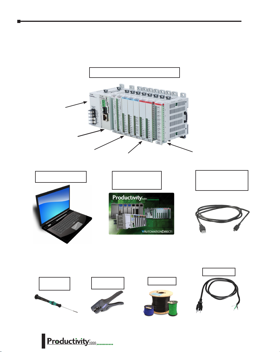
It is recommended that the following items be available to make this short step-by-step
introduction to the Productivity1000 System go smoothly.
P1-01AC Power Supply
P1-540 CPU Module
Productivity®1000 System Example
Analog Input Modules
PC Running
Windows OS
Not available from
Automationdirect.com
Screwdriver
TW-SD-MSL-1
Output Modules
Productivity Suite
Programming Software
PS-PGMSW
Download software from our website
at: www.automationdirect.com under
“Programmable Controllers”.
Wire Strippers
DN-WS
P1-08TRS Output Module
USB-A to Micro USB-B
Programming Cable
AC Power Cord
Hookup Wire
1–4
Not available from
Automationdirect.com.
Hardware User Manual, 1st Ed. Rev. L
Page 20

Productivity Suite System Requirements
Productivity Suite, a Windows-based programming software, is available as a FREE download
at https://support.automationdirect.com/downloads.html. Please check our website for this
product’s current operating systems requirements.
NOTE: USB or Ethernet cable is also required for communications between PC and CPU.
Chapter 1: Getting Started
Hardware User Manual, 1st Ed. Rev. L
1–5
Page 21

Chapter 1: Getting Started
Step 1: Install Programming Software
1. Download the latest version of the Productivity Suite Programming
Software from the Automationdirect website. Or, if the Productivity
Suite Programming Software CD is available, insert it into your PC CD
drive. The install dialog box should appear after a short time.
2. Click on the Start menu icon (bottom left corner of screen), and select Run or
for Windows 7 users, type “run” in the search field to locate this application.
• Type the following in the Open text field: D: install.exe, where D: is the drive letter of the
CD drive being used, or browse to the location of the “install.exe” file that was downloaded
and selected this file.
• Select OK and follow the dialog boxes shown throughout the next pages.
1–6
NOTE: See the Productivity Suite Installation and Productivity Suite Startup topics for additional details if
needed.
3. The “InstallAnywhere” pop-up (shown below) will appear
briefly while the software is preparing to install.
• The progress pop-up (shown below) will appear while the software is setting up the
directory.
Hardware User Manual, 1st Ed. Rev. L
Page 22
Chapter 1: Getting Started
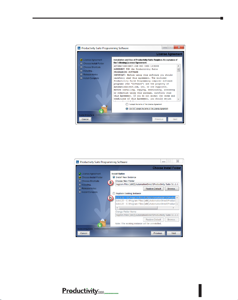
4. Carefully read the software license agreement. If you agree to the
terms and conditions of this agreement, select the “I accept the terms
of the License Agreement” and then the “Next” button.
5. The “Choose Install Folder” window will open next. If this is the first
installation of the Productivity Suite Software on your PC, choose
(a) Install New Instance: This option will install a new instance of the Productivity Suite
software in the default location, C:\Program Files\AutomationDirect\Productivity Suite
<Software Version>; or choose a different location using the Browse button.
If the installer detects a previous version of Productivity Suite on your PC, there is another
option available with this window:
(b) Replace Existing Instance: This option allows you to uninstall the previous version of the
software and install the new version in its place. If this option is chosen the following window
appears. Click “Uninstall” to continue.
Hardware User Manual, 1st Ed. Rev. L
1–7
Page 23
Chapter 1: Getting Started
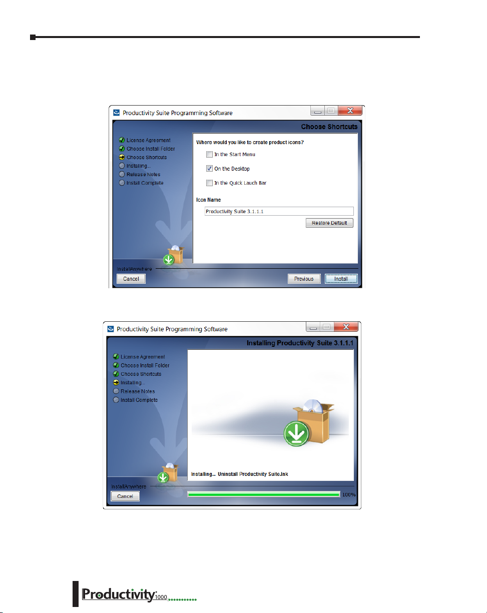
6. Once you have selected the install folder and whether or not to delete any previous
instances, the “Choose Shortcuts” window will appear. If a Shortcut Icon is desired for
the software select the location where the icon will be created. The default location is
“On the Desktop”. Once all selections have been made, click “Install” to begin the installation.
A status window will appear displaying the status of the installation.
1–8
Hardware User Manual, 1st Ed. Rev. L
Page 24
Chapter 1: Getting Started
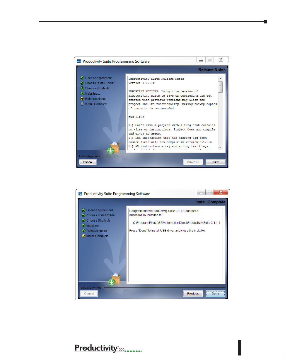
7. The next screen to appear contains the Release Notes for this version of the Productivity Suite
software. This is an opportunity to review the software version release notes. You may read
these before selecting the “Next” button.
8. The Installation is now complete. Select “Done”.
Hardware User Manual, 1st Ed. Rev. L
1–9
Page 25
Chapter 1: Getting Started
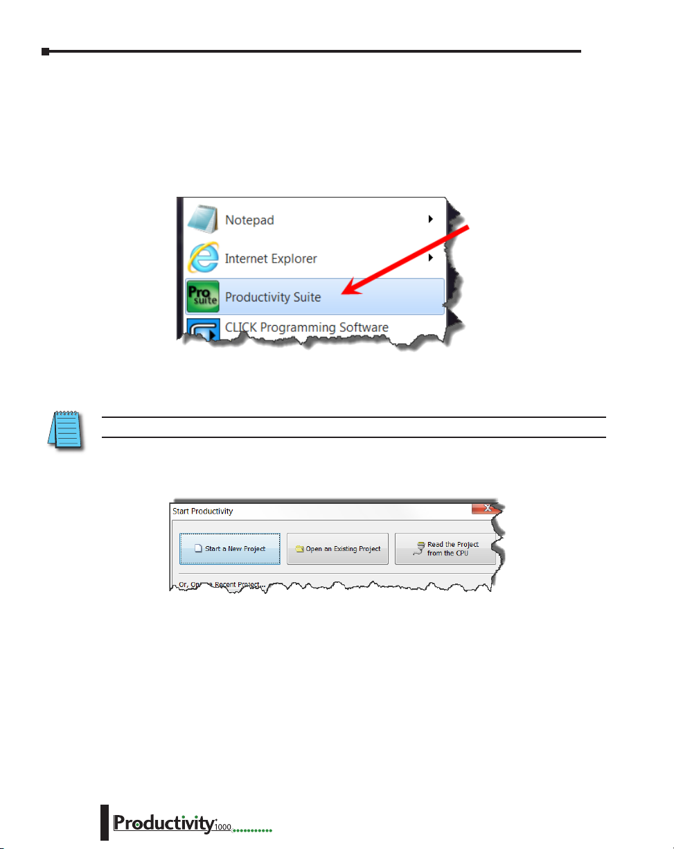
Step 2: Launch Programming Software
After installing the Productivity Suite Programming Software, PS-PGMSW, launch the software
by double clicking the desktop Productivity Suite Icon. Or from the PC’s ‘Start’ menu, slide
the mouse pointer through the menus (start>All Programs>AutomationDirect>Productivity
Suite x.x.x.x>Productivity Suite) to the Productivity Suite Programming Software selection,
and use the left mouse button to click on it.
The Productivity Suite Programming Software will start up and display the Main Window as
shown here.
NOTE: The recommended minimum screen size for the Productivity Suite Software is 1024 X 786 pixels.
1–10
Click on the ‘Start a New Project’ in the Start Productivity dialog box to open a programming
window.
Hardware User Manual, 1st Ed. Rev. L
Page 26
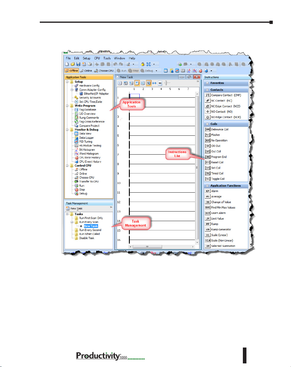
Chapter 1: Getting Started
The Programming Window is divided into menus and toolbars that work together to make
project development as simple as possible.
Online Help
It is essential that you use the Productivity Suite online Help to familiarize yourself with the
software. Keep it open on your desktop and refer to it frequently as you build your system.
Click on the toolbar Help button to open the Help file.
Hardware User Manual, 1st Ed. Rev. L
1–11
Page 27
Chapter 1: Getting Started
24VDC
Step 3: Install Hardware
The Productivity®1000 CPU system components snap together to form a configured CPU
in minutes. See Chapter 5, Installation and Wiring, for more detailed hardware installation
information. What follows are the basic steps:
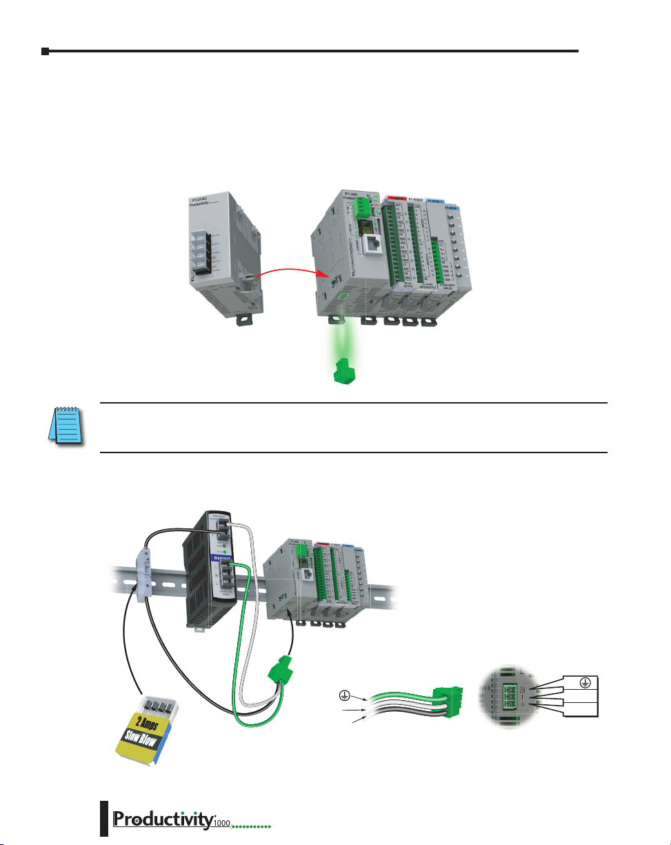
1. Connect power supply to CPU.
Align Power Supply
Connector and pilot
pins slide onto
P1 CPU module.
NOTE: Optional Power Connector must be removed before connecting a Productivity1000 Power Supply.
This precludes connection of two separate power supplies.
Remove Optional
Power Connector
1–12
2. OR using an alternate power source connect directly to CPU Optional Power Connector
terminals.
G
0V
24VDC
Use ADC
Part # S5062-R
G
0V
Hardware User Manual, 1st Ed. Rev. L
Page 28
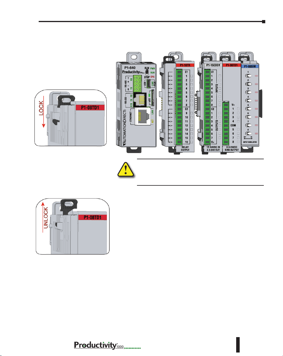
3. Install I/O Modules and engage locking tabs.
Step One:
With latch in “locked” position, align
connectors on the side of each module
and stack by pressing together. An
audible click indicates lock is engaged.
Chapter 1: Getting Started
Step Two:
To unstack modules, pull locking latch up
into the unlocked position and then pull
modules apart.
WARNING: Explosion hazard – Do not connect, disconnect
modules or operate switches while circuit is live.
Productivity®1000 System does not support Hot Swapping!
Hardware User Manual, 1st Ed. Rev. L
1–13
Page 29
Chapter 1: Getting Started
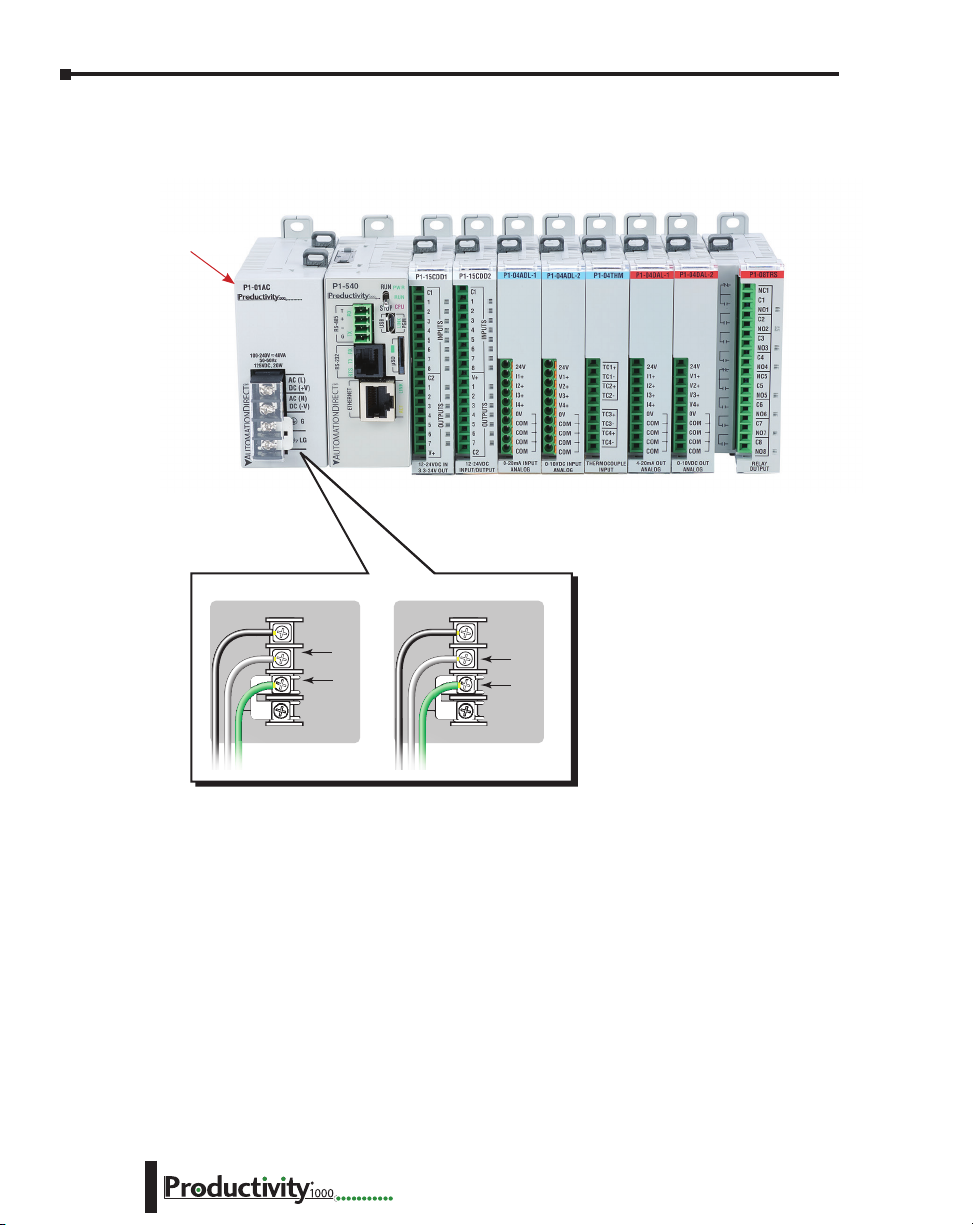
P1-01A C
AC (L)
AC (N)
G
LG
100-240V 48VA
50-60Hz
125VDC, 20W
DC (+V)
DC (-V)
®
125VDC 100–240 VAC
4. Connect appropriate wiring to the power supply (P1-01AC) and I/O (P1-08TRS module) in
this example.
P1-01AC
The power supply and load
are connected through a DC
1–14
DC (+V)
DC (-V)
GND
LOGIC
GND
or AC current source.
Hardware User Manual, 1st Ed. Rev. L
AC (L)
AC (N)
GND
LOGIC
GND
Page 30
Chapter 1: Getting Started
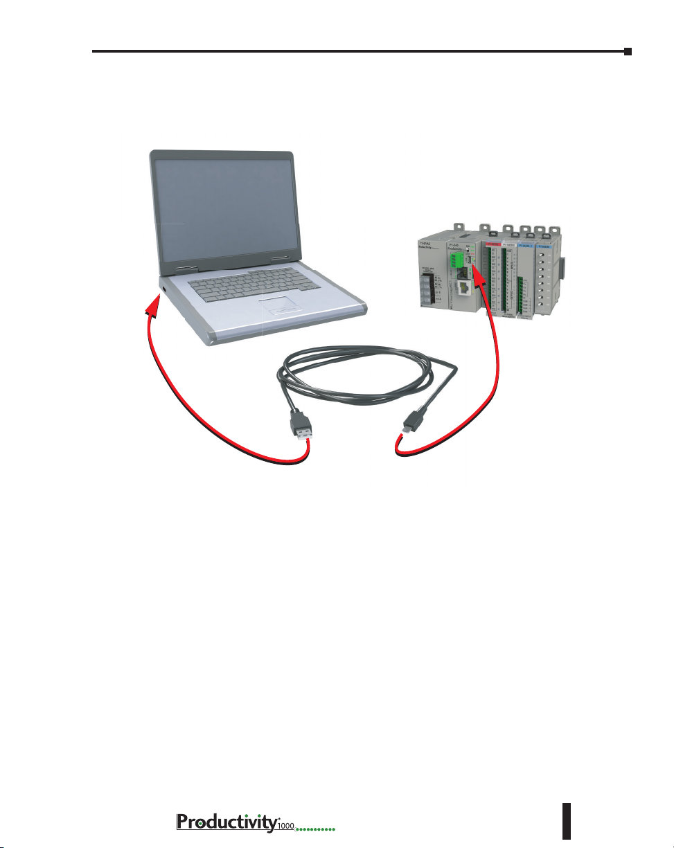
5. Connect USB cable. Use a Micro USB cable with a Type A and Micro Type B connectors as
shown below.
Hardware User Manual, 1st Ed. Rev. L
1–15
Page 31

Chapter 1: Getting Started
Step 4: Apply Power to CPU
Ensure proper wiring and the correct voltage is available before connecting wiring to the power
supply. Once this is verified, connect power to the power supply. Once power is applied, the
CPU will perform a self evaluation and verification. See Chapters 2 and 5 of this manual for
more power supply and I/O wiring information.
Step 5: Establish PC to CPU Communications
Select “Choose CPU” icon on the CPU Toolbar and the dialog box shown below will appear.
Highlight the installed CPU listed in the dialog box and select “Connect”.
1–16
When initially going Online with the CPU, a pop-up window will notify you of a project
difference between the CPU and the PC. Select “No, Use PC Project” command button.
Hardware User Manual, 1st Ed. Rev. L
Page 32

Chapter 1: Getting Started
Step 6: Open/Read Hardware Configuration
Before we create a project we must configure the hardware so we’ll have default input and output
tags for use in our project. With the CPU in “STOP” Mode, select Hardware Configuration
under Application Tools and the following screen opens.
Hardware User Manual, 1st Ed. Rev. L
1–17
Page 33

Chapter 1: Getting Started
The Module Configuration screen shows the user tag names for all eight I/O points.
Select “OK”.
1–18
Hardware User Manual, 1st Ed. Rev. L
Page 34

Step 7: Create a Project
We will start a new project by entering a simple ladder logic program in the order that follows.
Rung #1
Select the “END” position on Rung #1 with your cursor. From the Instruction List on the
right, scroll down to Counters/Timers section and double click on the Simple Timer (STMR)
instruction. The “Simple Timer” instruction is automatically placed on the selected rung and
the Simple Timer (STMR) dialog box pops up.
1. Enter ‘T1_SP’ into the Preset Value field.
2. Enter ‘T1_CURVAL’ into the Current Value field.
3. Enter ‘T1_DN’ into the Done field.
Chapter 1: Getting Started
4. Select “OK”.
The Define Tags dialog box opens.
5. Enter preset time value of 300 (ms) into “Initial Value” field for Tag T1_SP. Select OK.
Hardware User Manual, 1st Ed. Rev. L
1–19
Page 35

Chapter 1: Getting Started
Place the cursor on the first position on Rung #1 as shown below. In the Instruction List
on the right, scroll up to Contacts section and double click on “NO Contact (NO)”. A NO
Contact (NO) is placed at this rung position and a dialog box pops up.
1. Enter ‘T1_Start’ into the text box.
2. Select OK.
• The Define Tags dialog box opens. Select “OK”.
1–20
Hardware User Manual, 1st Ed. Rev. L
Page 36

Chapter 1: Getting Started
With the cursor on Rung #1, to the right of contact ‘T1_Start’, we are going to begin drawing
a branch circuit. Under the Edit drop down menu, select “Wire”, then select “Down”. Notice
that a wire has been added.
NOTE: There is also a wire Erase With Cursor tool in the Edit drop down menu that is used to erase any
lines that were created using the Wire tools.
Hardware User Manual, 1st Ed. Rev. L
1–21
Page 37

Chapter 1: Getting Started
Next we’ll draw a wire to the left. Under the Edit drop down menu, select “Wire”, then select
“Left”.
Next we’ll add another normally-open contact. Place the box cursor on the first position on the
newly created SubRung #1. From the Instruction List click & drag a Contact (NO) into this
box. A NO Contact (NO) dialog box pops up.
1. Enter ‘T1_Manual’ into the field.
2. Select “OK”.
1–22
The Define Tags dialog box opens. Select “OK”.
Hardware User Manual, 1st Ed. Rev. L
Page 38

Chapter 1: Getting Started
Rung #2
Next we’ll add another normally-open contact at the start of Rung #2. Click & drag a “NO
Contact (NO)” into this box. A NO Contact (NO) dialog box pops up.
1. In the empty tag field press the down arrow on the right to open
a drop-down list; scroll down and select ‘T1_DN’.
2. Select “OK”.
Next we’ll add an Out coil at the end of the rung. Place the cursor at the end of the rung.
From the Instructions list Coil section, double click on an “Out Coil (OUT)”. An Out Coil
(OUT) is placed on the rung and a dialog box pops up.
1. In the tag field press the down arrow on the right to open a dropdown list; scroll down and select ‘DO-0.1.2.1’.
2. Select OK.
Hardware User Manual, 1st Ed. Rev. L
1–23
Page 39

Chapter 1: Getting Started
The ladder program now looks like this. When either of the T1 contacts are energized, the
timer starts. When it times out, contact T1_DN energizes and turns on the rung 2 output.
1–24
Hardware User Manual, 1st Ed. Rev. L
Page 40

Step 8: Save Project
Save the project by opening the File drop-down menu and selecting Save Project.
Chapter 1: Getting Started
Hardware User Manual, 1st Ed. Rev. L
1–25
Page 41

Chapter 1: Getting Started
Step 9: Write Project to CPU
Next we will transfer the project to the CPU. Transfer Project is accessed by selecting Transfer
Project from the File Menu.
Select “To CPU” from the Transfer Project menu.
The project will then be Transferred to the CPU from the PC. During the transfer a status
window will open displaying the process.
1–26
Hardware User Manual, 1st Ed. Rev. L
Page 42

Step 10: Place CPU in RUN Mode
Next, verify the Run/Stop switch on the CPU faceplate is placed in the Run position and
then place the CPU in RUN mode on the Productivity Software Toolbar so the ladder logic
program executes.
NOTE: If the Run/Stop switch on the CPU is in the Stop position, the Run button on the Programming
Software Toolbar will be disabled.
Chapter 1: Getting Started
Hardware User Manual, 1st Ed. Rev. L
1–27
Page 43

Chapter 1: Getting Started
Step 11: Test the Project Using Monitor Mode
In this next step, use the Monitor Mode and Data View to test the ladder logic program. Select
Monitor Mode from the top of the Ladder Logic screen to display the status of Boolean and
Integer Tags.
Using Data View, the Tag values can be viewed or manipulated for testing the project. The
Data View window can be accessed by selecting Data View from the Tools Menu of the Main
Menu.
For the Simple Timer Instruction, a Monitor button is provided that, when selected, will load
the tags associated with the instruction into Data View.
1–28
Hardware User Manual, 1st Ed. Rev. L
Page 44

Chapter 1: Getting Started
The tags will be placed in a separate Tab titled New Task - STMR as seen below.
The remaining tagnames in the Ladder Logic can be added to the Data View window by
clicking on a blank area in the Tagname column. This will display a drop down menu where
the tags can be selected. Scroll down the list and select the tags to be added.
Hardware User Manual, 1st Ed. Rev. L
1–29
Page 45

Chapter 1: Getting Started
Once all of the tagnames have been added, they can now be monitored and manipulated. See
the Data View help file topic for additional details if needed.
NOTE: Force must be enabled for a Tag in the Tag Database before Force can be used in Data View.
1–30
Hardware User Manual, 1st Ed. Rev. L
Page 46

Chapter
Chapter
Chapter
SpecificationS
2
2
2
In This Chapter...
Overview .................................................................................................................... 2–4
P1000 Power Supplies ...............................................................................................2–5
P1-01AC and P1-02AC Power Supply ....................................................................... 2–5
Power Connections ..................................................................................................2–8
Grounding ...............................................................................................................2–8
P1-01DC Power Supply ........................................................................................... 2–9
Power Connections ................................................................................................2–10
Grounding .............................................................................................................2–10
Productivity®1000 Alternate Power Supply Connection ..........................................2–11
Productivity®1000 CPU Module ............................................................................... 2–12
P1-540 CPU Specifications......................................................................................2–12
Productivity®1000 CPU Module ............................................................................... 2–13
P1-540 Module Faceplate Layout ...........................................................................2–13
P1-540 Battery .......................................................................................................2–14
P1-540 Communication Ports ................................................................................2–15
MicroUSB Programming Port .................................................................................2–15
P1-540 Ethernet Port .............................................................................................. 2–16
microSD Slot .......................................................................................................... 2–17
RS-232 Port ............................................................................................................ 2–18
RS-485 Port ............................................................................................................ 2–19
Productivity®1000 CPU Module ............................................................................... 2–20
P1-550 CPU Specifications......................................................................................2–20
Productivity®1000 CPU Module ............................................................................... 2–21
P1-550 Module Faceplate Layout ...........................................................................2–21
P1-550 Battery .......................................................................................................2–22
Page 47

Table of Contents
P1-550 Communication Ports ................................................................................2–23
MicroUSB Programming Port .................................................................................2–23
P1-550 Ethernet Port .............................................................................................. 2–24
microSD Slot .......................................................................................................... 2–25
RS-232 Port ............................................................................................................ 2–26
RS-485 Port ............................................................................................................ 2–27
I/O Modules Overview ............................................................................................2–28
Discrete I/O Modules ..............................................................................................2–29
Discrete Input Modules ..........................................................................................2–29
Discrete Output Modules .......................................................................................2–29
Discrete Combo I/O Modules .................................................................................2–30
Discrete Combo Input/Output Modules ................................................................. 2–30
I/O Modules Installation..........................................................................................2–30
P1-08SIM Input Simulator Module .........................................................................2–31
P1-08ND3 Sinking/Sourcing DC Input .................................................................... 2–32
Wiring Diagrams ....................................................................................................2–34
P1-16ND3 Sinking/Sourcing DC Input .................................................................... 2–35
Wiring Diagrams ....................................................................................................2–37
P1-08NE3 AC/DC Sinking/Sourcing Input ..............................................................2–38
Wiring Diagrams ....................................................................................................2–40
P1-16NE3 AC/DC Sinking/Sourcing Input ..............................................................2–41
Wiring Diagrams ....................................................................................................2–43
P1-08NA AC Input ...................................................................................................2–44
Wiring Diagrams ....................................................................................................2–46
P1-08TD1 Sinking DC Output .................................................................................2–47
Wiring Diagrams ....................................................................................................2–49
P1-08TD2 Sourcing DC Output ...............................................................................2–50
Wiring Diagrams ....................................................................................................2–52
P1-15TD1 Sinking DC Output .................................................................................2–53
Wiring Diagrams ....................................................................................................2–55
P1-15TD2 Sourcing DC Output ...............................................................................2–56
Wiring Diagrams ....................................................................................................2–58
2–2
Hardware User Manual, 1st Ed. Rev. L
Page 48

Table of Contents
P1-08TA AC Output .................................................................................................2–59
Wiring Diagrams ....................................................................................................2–61
P1-08TRS Isolated Relay ..........................................................................................2–62
Wiring Diagrams ....................................................................................................2–64
P1-16TR Relay Output .............................................................................................2–65
Wiring Diagrams ....................................................................................................2–67
P1-15CDD1 Input/Output .......................................................................................2–68
Wiring Diagrams ....................................................................................................2–70
P1-15CDD2 Input/Output .......................................................................................2–71
Wiring Diagrams ....................................................................................................2–73
P1-16CDR Discrete Input/ Relay Output .................................................................2–74
Wiring Diagrams ....................................................................................................2–76
Hardware User Manual, 1st Ed. Rev. L
2–3
Page 49

Chapter 2: Specifications
Overview
Hardware
The Productivity®1000 system of components is designed to combine practical PLC
features in a compact and expandable design, with a simple-to-use philosophy. A powerful
Productivity1000 PLC can be expanded with the addition of easily connected I/O modules.
The Productivity1000 PLC system does not require a mounting base. The Productivity1000
PLC and I/O modules are connected together via an expansion port on the right side of the
PLC case. A variety of I/O modules are available for flexible and optimal system configuration.
The Productivity1000 PLC is supported by the robust and powerful Productivity Suite
programming software; designed with an easy-to-use instruction set that covers all applications
suitable for this class of PLC. The CPU stores and executes the user designed program.
2–4
Hardware User Manual, 1st Ed. Rev. L
Page 50

P1000 Power Supplies
Three power supplies are available for the P1000, providing either AC or DC source power
choices. P1-01AC and P1-02AC provide two choices for AC sourcing of power, 16W and
26W respectively, and the P1-01DC provides 16W power from a DC source.
P1-01AC and P1-02AC Power Supplies
These AC power supplies require an external 100–240 VAC source and provide isolated
24VDC to the Productivity1000 P1-540 or P1-550 CPU system.
Chapter 2: Specifications
P1-01AC
100-240V 48VA
125VDC, 20W
50-60Hz
®
AC (L)
DC (+V)
AC (N)
DC (-V)
G
LG
P1-02AC
100-240V 74VA
125VDC, 33W
50-60Hz
P1-01AC (16W) P1-02AC (26W)
Terminal Block Specications
Number of positions
Wire Range
Conductors
Screw Driver
Screw Size
Screw Torque
*Recommended screw driver P/N: TW-SD-MSL-2
4 screw terminals
22–12 AWG (0.324 to 3.31 mm²)
Solid / tranded conductor
3/64 in (1.2 mm) insulation max.
1/4 in (6–7 mm) trip length
Use copper conductors, 75°C or equivalent
1/4 in (6.5 mm) maximum
M3
7–9 lb·in (0.882–1.02 N·m)
™
AC (L)
DC (+V)
AC (N)
DC (-V)
G
LG
Hardware User Manual, 1st Ed. Rev. L
2–5
Page 51

Chapter 2: Specifications
P1-01AC Power Supply
The P1-01AC Universal Power Supply provides isolated, 16W of power to the Productivity1000
system from an external 100–240 VAC or 125VDC source.
P1-01AC
P1-01AC
100-240V 48VA
50-60Hz
125VDC, 20W
®
AC (L)
DC (+V)
AC (N)
DC (-V)
G
LG
IMPORTANT!
Hot-Swapping Information
Note: This device cannot be Hot
Swapped.
NOTE: P1-01AC provides 16W
of power to support a CPU and
up to 8 expansion modules.
User Specications
Input Voltage Range (Tolerance)
Rated Operating Frequency
Maximum Input Power
Cold Start Inrush Current
Maximum Inrush Current (Hot Start)
Input Fuse Protection (Internal)
Output Voltage
Maximum Output Power
Isolated User 24VDC Output
Output Protection for Over Current,
Over Voltage, and Over Temperature
Under Input Voltage Lock-out
Input Transient Protection
Operating Design Life
General Specications
Surrounding Air Temperature
Storage Temperature
Humidity
Environmental Air
Vibration
Shock
Insulation Resistance
Heat Dissipation
Enclosure Type
Voltage Withstand (dielectric)
Module Location
Weight
Agency Approvals
*See CE Declaration of Conformity for details.
0°C– 60°C (32°F–140°F)
-20ºC–70ºC (-4ºF–158ºF)
5 to 95% (non-condensing)
No corrosive gases permitted
IEC60068-2-6 (Test Fc)
IEC60068-2-27 (Test Ea)
5000mW
Open equipment
2100VDC applied for 2s
Power upply latches to CPU in the module
stacking Productivity1000 system.
146g (5.1 oz)
UL 61010-1 and UL 61010-2-201 file
E139594, Canada and USA
CE (EN 61131-2 EMC, EN 61010-1 and
EN 61010-2-201 Safety)*
100–240 VAC (-15% / +10%)
125VDC (-15% / +20%)
50 to 60Hz with ±5% tolerance
48VA (AC) 20W (DC)
21A
21A
Micro fuse 250V, 1A
Non-replaceable
75%
24VDC, 0.67 A
16W
None
Self resetting
40–75 VAC - 24VDC On @ 76.15 VAC
55–99 VDC - 24VDC On @ 100.2 VDC
10 years at full load at 40°C ambient and
5 years at 60°C ambient
2–6
Hardware User Manual, 1st Ed. Rev. L
Page 52

Chapter 2: Specifications
P1-02AC Power Supply
The P1-02AC Universal Power Supply provides isolated, 26W power to the Productivity1000
system from an external 100–240 VAC or 125VDC source.
P1-02AC
P1-02AC
100-240V 74VA
50-60Hz
125VDC, 33W
™
AC (L)
DC (+V)
AC (N)
DC (-V)
G
LG
IMPORTANT!
Hot-Swapping Information
Note: This device cannot be Hot
Swapped.
NOTE: P1-02AC provides 26W
of power to support a CPU and
up to 15 expansion modules.
User Specications
Input Voltage Range (Tolerance)
Rated Operating Frequency
Maximum Input Power
Cold Start Inrush Current
Maximum Inrush Current (Hot Start)
Input Fuse Protection (Internal)
Output Voltage
Maximum Output Power
Isolated User 24VDC Output
Output Protection for Over Current,
Over Voltage, and Over Temperature
Under Input Voltage Lock-out
Input Transient Protection
Operating Design Life
General Specications
Surrounding Air Temperature
Storage Temperature
Humidity
Environmental Air
Vibration
Shock
Insulation Resistance
Heat Dissipation
Enclosure Type
Voltage Withstand (dielectric)
Module Location
Weight
Agency Approvals
*See CE Declaration of Conformity for details.
0°C– 60°C (32°F–140°F)
-20ºC–70ºC (-4ºF–158ºF)
5 to 95% (non-condensing)
No corrosive gases permitted
IEC60068-2-6 (Test Fc)
IEC60068-2-27 (Test Ea)
6200mW
Open equipment
2100VDC applied for 2s
Power Supply latches to CPU in the module
stacking Productivity1000 system.
164g (5.8 oz)
UL 61010-1 and UL 61010-2-201 File E139594,
Canada and USA
CE (EN 61131-2 EMC, EN 61010-1 and
EN 61010-2-201 Safety)*
100–240 VAC (-15% / +10%)
125VDC (-15% / +20%)
50 to 60Hz with ±5% tolerance
74VA (AC) 33W (DC)
21A
21A
Micro fuse 250V, 2A
non-replaceable
81%
24VDC, 1.08 A
26W
None
Self resetting
40–75 VAC - 24VDC On @ 76.15 VAC
55–99 VDC - 24VDC On @ 100.2 VDC
10 years at full load at 40°C ambient and
5 years at 60°C ambient
Hardware User Manual, 1st Ed. Rev. L
2–7
Page 53

Chapter 2: Specifications
P1-02A C
AC (L)
AC (N)
G
LG
100-240V 74VA
50-60Hz
125VDC, 33W
DC (+V)
DC (-V)
™
Power Connections
P1-01AC P1-02AC
P1-01AC
100-240V 48VA
125VDC, 20W
50-60Hz
®
AC (L)
DC (+V)
AC (N)
DC (-V)
LG
G
P1-02AC
100-240V 74VA
125VDC, 33W
50-60Hz
™
AC (L)
DC (+V)
AC (N)
DC (-V)
G
LG
125VDC 100–240 VAC
+V
-V
Grounding
A good common ground reference (earth ground) is essential for proper operation of the
Productivity®1000 system. One side of all control circuits, power circuits and the ground lead
must be properly connected to earth ground by either installing a ground rod in close proximity
to the enclosure or by connecting to the incoming power system ground. There must be a
single-point ground (i.e. copper bus bar) for all devices in the enclosure that require an earth
GND
LOGIC
GND
AC (L)
AC (N)
GND
LOGIC
GND
ground.
2–8
Hardware User Manual, 1st Ed. Rev. L
Page 54

P1-01DC Power Supply
P1-01DC
P1-01DC
™
12-24V 21W
+V
-V
G
LG
Chapter 2: Specifications
P1-01DC User Specications
Input Voltage Range
(Tolerance)
Maximum Input Power 21W
Cold Start Inrush Current 34A
Maximum Inrush Current
(Hot Start)
Input Fuse Protection
(Internal)
Efficiency
Output
Maximum Output Power 16W
Isolated User 24VDC Output None
Output Protection for Over
Current, Over Voltage and
Over Temperature
Under Input Voltage Lock-out < 9VDC
Over Input Voltage Lock-out None
Input Transient Protection Varistor, plus input choke and filter
Operating Design Life
12–24 VDC (-10% / +20% at 60°C)
34A
Micro fuse 250V, 4A,
non-replaceable
75%
24VDC, 0.67 A
Positive Temperature Coefficient (PTC) resettable
fuse, resets when load removed.
10 years at full load at 40°C (104°F) ambient and
5 years at 60°C (140°F) ambient
IMPORTANT!
Hot-Swapping Information
Note: This device cannot be Hot
Swapped.
NOTE: P1-01DC provides 16W
of power to support a CPU and
up to 8 expansion modules.
P1-01DC General Specications
Operating Temperature
Storage Temperature -20ºC–70ºC (-4ºF–158ºF)
Humidity 5 to 95% (non-condensing)
Environmental Air No corrosive gases permitted
Vibration IEC60068-2-6 (Test Fc)
Shock IEC60068-2-27 (Test Ea)
Insulation Resistance
Heat Dissipation 5W
Enclosure Type Open equipment
Voltage Withstand
(dielectric)
Module Location
Weight 146g (5.15 oz)
Agency Approvals
*See the Declaration of Conformity for details.
Hardware User Manual, 1st Ed. Rev. L
0°C– 60°C (32°F–140°F)
>10MV @ 500VDC
750VDC applied for 2s
Power supply slot in a Productivity1000 system.
UL 61010-1 and UL 61010-2-201 File E139594,
Canada and USA
CE (EN 61131-2 EMC, EN 61010-1 and
EN 61010-2-201 Safety)*
2–9
Page 55

Chapter 2: Specifications
Power Connections
P1-01DC
P1-01DC
12-24V 21W
™
+V
-V
G
LG
+V
-V
GND
LOGIC
GND
Grounding
2–10
A good common ground reference (earth ground) is essential for proper operation of the
Productivity1000 system. One side of all control circuits, power circuits and the ground
lead must be properly connected to earth ground by either installing a ground rod in close
proximity to the enclosure or by connecting to the incoming power system ground. There
must be a single-point ground (i.e., copper bus bar) for all devices in the enclosure that require
an earth ground.
Hardware User Manual, 1st Ed. Rev. L
Page 56

Chapter 2: Specifications
Removable Terminal Block Specifications
P1-PWRCON (Included in PCON-KIT)
3 Screw Terminals
3.5 mm
28–12 AWG Solid Conductor
30–12 AWG Stranded Conductor
1/8 in (3.175 mm) Maximum
M2.5
4.5 lb·in (0.51 N·m)
Productivity®1000 Alternate Power Supply Connection
All Productivity1000 CPUs require 24VDC input power. When using an alternative
24VDC power source, connect power supply wiring to the bottom removable terminal block
as shown below.
P1-540
T
RXTXTXRTSRX
+
-
G
RS-232 RS-485
ETHERNET
REMOTE I/O
P1-540 or P1-550
NOTE: If you do not use a Productivity1000 power supply (P1-01AC, P1-02AC or P1-01DC), then use
a power supply that has transformer isolation. Use separate 24VDC power supplies for the CPU and
inductive loads to keep the CPU power clean and free of voltage spikes caused by switching solenoids,
motors and relay coils.
RUN
PWR
®
RUN
CPU
STOP
USB
PGM
LINK
Power
Terminal
µSD
ACT LINK
LINK ACT
10/100
Removable Terminal Block Specications
Part Number
Number of Positions
Pitch
Wire Range
Screw Driver
Screw Size
Screw Torque
LG
+
Removable connector included.
Spare connectors available
(part no. PCON-KIT).
PCON-KIT (Includes power terminal block)
3 crew terminals
3.5 mm
28–16 AWG olid onductor
28–16 AWG tranded onductor
1/8 inch (3.175 mm) maximum
M2
1.7 lb·in (0.4 N·m)
Pin Signal
LG
Ground
–
24V DC –
+
24V DC +
* Recommended fuse: 2A slow blow
Hardware User Manual, 1st Ed. Rev. L
2–11
Page 57

Chapter 2: Specifications
Productivity®1000 P1-540 CPU Module
P1-540 CPU Specifications
P1-540
T
+
-
G
RS-232 RS-485
ETHERNET
REMOTE I/O
P1-540
RUN
PWR
®
RUN
CPU
STOP
RXTXTXRTSRX
USB
PGM
LINK
µSD
ACT LINK
LINK ACT
10/100
IMPORTANT!
Hot-Swapping Information
Note: This device cannot be Hot
Swapped.
CPU
P1-540 Version 3.0 or later
* If you do not use one of the Productivity1000 power
supplies (P1-01AC, P1-02AC or P1-01DC), then use a power
supply that has transformer isolation. Use different 24VDC
supplies for the CPU and inductive loads to keep the CPU
power clean and free of voltage spikes caused by switching
solenoids, motors and relay coils.
Productivity Suite
CPU Specications
User Memory
Memory Type
Retentive Memory
Scan Time
External Power
Voltage Range*
Communications;
4 Integrated Ports
Data Logging
Hardware Limits
of System
Instruction Types
Real Time Clock
Accuracy
*If used with 26W or larger power supply.
50MB (Includes program, data and documentation)
Flash and Battery Backed RAM
500kB
1.3 ms (1K Boolean, 128 I/O)
24VDC ±2% @ 5W
plus 1.25 W per additional I/O module
USB IN: Programming, Monitoring, Debug, Firmware
Ethernet: (10/100 Mbps Ethernet) Programming,
Monitoring, Debug, Firmware, Email SMTP Client,
Modbus TCP Client (16 Servers) and Server (16
Clients), EtherNet/IP Scanner (32) and Adapter (4),
Custom Protocol over Ethernet, ProNET.
RS-232: (RJ12, 1200–115.2k baud) ASCII, Modbus
RS-485: Removable Terminal Included,
(1200–115.2k baud) ASCII, Modbus RTU
microSD card slot
240 Hardware I/O Points: All 15 (16-point I/O
Modules)*
Application Functions
Array Functions
Counters/Timers
Communications
Data Handling
Drum Sequencers
Math Functions
±2s per day typical at 25°C
±10s per day maximum at 60°C
General Specications
Surrounding Air Temperature
Storage Temperature
Humidity
Environmental Air
Vibration
Shock
Heat Dissipation
Enclosure Type
Module Location
Weight
Agency Approvals
0°C– 60°C (32°F–140°F)
-20ºC–70ºC (-4ºF–158ºF)
5 to 95% (non-condensing)
No corrosive gases permitted
IEC60068-2-6 (Test Fc)
IEC60068-2-27 (Test Ea)
3810mW
Open equipment
Controller connector on the side of the power
supply in a Productivity1000 system.
136g (4.8 oz)
UL 61010-1 and UL 61010-2-201 File
E139594, Canada and USA
CE (EN 61131-2 EMC, EN 61010-1 and
EN 61010-2-201 Safety)*
PID
Program Control
String Functions
System Functions
Contacts
Coils
2–12
*See CE Declaration of Conformity for details.
Hardware User Manual, 1st Ed. Rev. L
Page 58

P1-540 Module Faceplate Layout
CPU Front Pane l
CPU Status Indicators
RS-485 Serial Port
- Modbus/ASCII
(master peripheral device
or multiple slave devices)
using the same protocol
RS-232 Serial Port (RJ12)
- Modbus/ASCII
(master or slave)
peripheral device
10/100 MB
Ethernet Port
- Programming
- Online monitoring
- Email (SMTP client)
- Ethernet IP Client
and Server
- Modbus TCP Client
and Server
- Custom Protocol
over Ethernet
- ProNet
External Power
- 24VDC
P1-540
T
+
G
RS-232 RS-485
-
RXTXTXRTSRX
ETHERNET
REMOTE I/O
Chapter 2: Specifications
CPU Status Indicators
PWR
RUN
™
STOP
USB
Micro USB 2.0 (Type B)
RUN
- Programming
CPU
- Online monitoring
- Firmware/Debug
PGM
LINK
microSD Port
- removable flash memory
µSD
ACT LINK
LINK ACT
10/100
P1-540
CPU Run/Stop Switch Specications
RUN position
STOP position
Executes user program, run-time edits possible.
Does not execute user program, normal program load
position.
CPU Status Indicators
PWR
RUN
CPU
Green LED is illuminated when power is
ON
Green LED is illuminated when CPU is in
RUN mode
Red LED is illuminated during power ON
reset, power down, or watch-dog time-out.
Hardware User Manual, 1st Ed. Rev. L
2–13
Page 59

Chapter 2: Specifications
Step One:
Step Two:
Take care to insert
battery behind tab.
P1-540 Battery
A battery is included with the P1-540 CPU module, but is not installed. The battery
may be installed in order to retain the time and date settings along with any tagname
values that are set up as retentive.
The battery is not required for program backup.
Open battery compartment
located on the top of the CPU
and pull up to locked position.
P1-540
Squeeze tabs and
pull battery holder up
to remove battery.
P1-540
Insert battery under top two tabs in
battery compartment. Press and snap
battery behind bottom tab then
close the battery compartment.
1. Secure
battery
under two
top tabs
P1-540
2. Press battery to
snap behind tab.
-
+
2–14
Battery (Optional)
D2-BAT-1
Note: Although not needed for program backup, an uninstalled battery is included
with the P1-540. Install this battery if you want the CPU to retain the Time and Date
along with any Tagname values that you have set up as retentive.
Coin type, 3.0 V Lithium battery, 560mA, battery number CR2354
Hardware User Manual, 1st Ed. Rev. L
Page 60

Chapter 2: Specifications
Standard Micro USB Slave input for programming and online
monitoring, with built-in surge protection. Not
compatible with older full speed USB devices.
480 Mbps
Green LED is illuminated when LINK is established to programming
software.
USB Type A to Micro USB Type B:
6ft cable part # USB-CBL-AMICB6
15ft cable part # USB-CBL-AMICB15
P1-540 Communication Ports
The P1-540 CPU has several communications ports. The following pages contain the
specifications and pin-out diagrams.
MicroUSB Programming Port
Used exclusively for connecting to a PC running
the Productivity Suite programming software.
P1-540
T
+
-
G
RS-232 RS-485
RXTXTXRTSRX
ETHERNET
RUN
PWR
®
STOP
USB
RUN
CPU
PGM
LINK
µSD
ACT LINK
Micro USB Input Specications
Port Name
Description
Transfer Rate
Port Status LED
Cables
MicroUSB
Standard MicroUSB Slave input for programming and
on-line monitoring, with built-in surge protection. Not
compatible with older full speed USB devices.
480 Mbps
Green LED is illuminated when LINK is established to
programming software.
USB Type A to MicroUSB Type B:
6ft cable part # USB-CBL-AMICB6
15ft cable part # USB-CBL-AMICB15
REMOTE I/O
LINK ACT
10/100
P1-540
1 VBUS
2 D-
USB
PGM
LINK
3 D+
4 ID
5 GND
Hardware User Manual, 1st Ed. Rev. L
2–15
Page 61

Chapter 2: Specifications
Port Specifications
Ethernet Specifications
Port Name ETHERNET
Description
Standard transformer isolated Ethernet port with built-in surge protection
for programming, online monitoring, Email (SMTP client), Modbus/TCP
client/server connections (fixed IP or DHCP) and Ethernet IP client/server
connections.
Transfer
Rate
10 Mbps and 100 Mbps (auto-crossover)
Port Status
LED
LINK (Amber LED) is solid when network LINK is established. ACT
(Green LED) flashes when port is active.
P1-540 Ethernet Port
P1-540
T
+
-
G
RS-232 RS-485
RUN
PWR
®
RUN
CPU
STOP
RXTXTXRTSRX
USB
PGM
LINK
µSD
RJ-45 style connector used for:
• Connection to a PC running the Productivity Suite
programming software
• Modbus TCP Client connections
(Modbus requests sent from the CPU)
• Modbus TCP Server connections
(Modbus requests received by the CPU)
• EtherNet/IP (Client/Server)
• Custom Protocol over Ethernet
• ProNET
• Outgoing Email
ETHERNET
REMOTE I/O
ACT LINK
LINK ACT
10/100
P1-540
Ethernet Specications
Port Name ETHERNET
Standard transformer isolated Ethernet port with built-in
Description
Transfer Rate
Port Status
LED
TD+
TD–
RD+
RD–
TD+
TD–
RD+
RD–
surge protection for programming, online monitoring, Email
IP or DHCP), EtherNet/IP Scanner/Apapter, Custom Protocol
over Ethernet and ProNET connections.
10 Mbps and 100 Mbps (auto-crossover).
LINK (Amber LED) is solid when network LINK is
Crossover Cable
OR/WHT
1
OR
2
GRN/WHT
3
BLU
4
BLU/WHT
5
GRN
6
BRN/WHT
7
BRN
8
RJ45 RJ45
Patch (Straight-through) Cable
OR/WHT
1
OR
2
GRN/WHT
3
BLU
4
BLU/WHT
5
GRN
6
BRN/WHT
7
BRN
8
RJ45 RJ45
GRN/WHT
GRN
OR/WHT
BLU/WHT
BRN/WHT
OR/WHT
GRN/WHT
BLU/WHT
GRN
BRN/WHT
TD+
1
TD–
2
RD+
3
BLU
4
5
OR
RD–
6
7
BRN
8
TD+
1
OR
TD–
2
RD+
3
BLU
4
5
RD–
6
7
BRN
8
10/BASE-T/100BASE-TX
8
1
1 2 3 4 5 6 7 8
8-pin RJ45 Connector
(8P8C)
2–16
Hardware User Manual, 1st Ed. Rev. L
Page 62

microSD Slot
PinSD
1
2
3
4
5
6
7
8
DAT2
CD/DAT3
CMD
VDD
CLK
VSS
DAT0
DAT1
Used for data logging.
Chapter 2: Specifications
P1-540
RS-232 RS-485
T
RXTXTXRTSRX
+
-
G
ETHERNET
REMOTE I/O
P1-540
RUN
PWR
®
RUN
CPU
STOP
USB
PGM
LINK
µSD
ACT LINK
LINK ACT
10/100
microSD Specications
Port Name
Description
Maximum Card
Capacity
Transfer Rate
(ADATA microSDHC
Class 4 memory card)
Port Status LED
microSD
Standard microSD socket for data logging
32GB
Mbps Minimum Typical Maximum
Read 14.3 14.4 14.6
Write 4.8 4.9 5.1
Green LED is illuminated when card is inserted/
detected
Pin SD
1
1
8
2
3
4
5
6
7
8
DAT2
CD/DAT3
CMD
VDD
CLK
VSS
DAT0
DAT1
Note: Card not included with unit.
Hardware User Manual, 1st Ed. Rev. L
2–17
Page 63

Chapter 2: Specifications
P1-540 RS-232 Port
P1-540
T
+
-
G
RUN
PWR
®
RUN
CPU
STOP
RXTXTXRTSRX
USB
PGM
LINK
RS-232 Port
RJ-12 style connector used for:
• Modbus RTU Master connections
• Modbus RTU Slave connections
• ASCII full or half duplex communications
• Custom Protocol Incoming and Outgoing
communications
RS-232 RS-485
ETHERNET
REMOTE I/O
µSD
ACT LINK
LINK ACT
10/100
RS-232 Specications
Port Name
Description
Data Rates
+5V Cable Power
Source
TXD
RXD
RTS
GND
Maximum Output
Load (TXD/RTS)
Minimum Output
Voltage Swing
Output Short
Circuit Protection
Port Status LED
Cable Options
RS-232
Non-isolated RS-232 DTE port connects the CPU as a
Modbus/ASCII master or slave to a peripheral device.
Includes ESD and built-in surge protection
Selectable,1200, 2400, 4800, 9600, 19200, 33600, 38400,
57600, and 115200 baud
210mA maximum at 5V, ±5%. Reverse polarity and
overload protected
RS-232 Transmit output
RS-232 Receive input
Handshaking output for modem control
Logic ground
3kΩ, 1000pf
±5V
±15mA
Green LED is illuminated when active for TXD, RXD and
RTS
EA-MG-PGM-CBL
D2-DSCBL
USB-RS232 with D2-DSCBL
FA-CABKIT
FA-ISOCON for converting RS-232 to isolated RS-485
2–18
Pin Label Signal
1 GND
1
2 +5V
3 RXD
4 TXD
6
5 RTS
6-Pin RJ12 Female
6 GND
Modular Connector
Hardware User Manual, 1st Ed. Rev. L
Logic Ground
210mA Maximum
RS-232 Input
RS-232 Output
RS-232 Output
Logic Ground
Page 64

P1-540 RS-485 Port
P1-540
T
+
-
G
RUN
PWR
®
RUN
CPU
STOP
RXTXTXRTSRX
USB
LINK
Chapter 2: Specifications
RS-485 Port
A 4-pin removable terminal block used for:
• Modbus RTU Master connections
• Modbus RTU Slave connections
PGM
• ASCII Incoming and Outgoing communications
• Custom Protocol Incoming and Outgoing communications
RS-232 RS-485
ETHERNET
REMOTE I/O
µSD
ACT LINK
LINK ACT
10/100
Pin Signal
T
Termination
+
TXD+/RXD+
–
TXD-/RXD-
G
GND
Removable connector included.
Spare connectors available
(part no. P3-RS485CON-1).
RS-485 Port Specications
Port Name
Description
Data Rates
TXD+/RXD+
TXD-/RXD-
GND
Input Impedance
Maximum Load
Output Short Circuit Protection
Electrostatic Discharge Protection
Electrical Fast Transient Protection
Fail Safe Inputs
Maximum Common Mode Voltage
Port Status LED
Cable Options
RS-485
Non-isolated RS-485 port connects the CPU as
a Modbus/ASCII master or slave to a peripheral
device. Includes ESD/EFT protection and automatic
echo cancellation when transmitter is active
Selectable, 1200, 2400, 4800, 9600, 19200, 33600,
38400, 57600, and 115200 baud
RS-485 transceiver high
RS-485 transceiver low
Logic ground
19kΩ
50 transceivers, 19kΩ each, 60Ω termination
±250mA, thermal shut-down protection
±8kV per IEC1000-4-2
±2kV per IEC1000-4-4
1.5 V with 60Ω load
Logic high input state if inputs are unconnected
-7.5 V to 12.5 V
Green LED illuminated when active for TXD and RXD
L19827-XXX from AutomationDirect.com
Removable Terminal Block Specications
Part Number
Number of Positions
Pitch
Wire Range
Screw Driver
Screw Size
Screw Torque
P3-RS485CON-1
4 crew terminals
3.5 mm
28–16 AWG olid onductor
28–16 AWG tranded onductor
1/8 inch (3.175 mm) maximum
M2
1.7 lb·in (0.4 N·m)
Hardware User Manual, 1st Ed. Rev. L
2–19
Page 65

Chapter 2: Specifications
Productivity1000 P1-550 CPU Module
P1-550 CPU Specifications
P1-550
T
+
-
G
RS-232 RS-485
P1-550
RXTXTXRTSRX
ETHERNET
REMOTE I/O
RUN
PWR
™
RUN
CPU
STOP
USB
PGM
LINK
µSD
ACT LINK
LINKACT
10/100
IMPORTANT!
Hot-Swapping Information
Note: This device cannot be Hot
Swapped.
CPU
P1-550 Version 3.5 or later
* If you do not use a Productivity1000 power supply
(P1-01AC, P1-02AC or P1-01DC), then use a power supply
that has transformer isolation. Use different 24VDC supplies
for the CPU and inductive loads to keep the CPU power clean
and free of voltage spikes caused by switching solenoids,
motors and relay coils.
Productivity Suite
CPU Specications*
User Memory
Memory Type
Retentive Memory
Scan Time
External Power
Voltage Range*
Recommended Fuse
(External)
Communications;
4 Integrated Ports
Data Logging
Hardware Limits
of System
Instruction Types
Real Time Clock
Accuracy
*GS-EDRV100-(GS1,2,3) and GS4-CM-MODTCP (GS4)
** If used with 26W or larger power supply.
50MB (Includes program, data and documentation)
Flash and Battery Backed RAM
500kB
1.5 ms (1K Boolean, 240 I/O)
24VDC ±2% @ 5W
plus 1.25 W per additional I/O module
Edison S5062-R, Time Delay. 2A Fuse
USB IN: Programming, monitoring, debug, firmware
Ethernet: (10/100 Mbps Ethernet) Programming, monitoring,
debug, firmware, Email SMTP client, Modbus TCP lient
(32 ervers) and erver (16 Clients), EtherNet/IP canner (32
Adapters) and Adapter (4 Scanners) with 8 connections per
device, Custom Protocol over Ethernet, ProNET.
Remote I/O: 16 GS Drives*, 4 ProtosX TCP couplers
RS-232: (RJ12, 1200–115.2k Baud) ASCII, Modbus
RS-485: removable terminal included,
(1200–115.2k Baud) ASCII, Modbus RTU
MicroSD card slot
240 Hardware I/O Points: All 15 (16-point I/O modules)**
16 GS Series Drives: as remote I/O
4 ProtosX TCP Couplers with 32 terminals each
Application functions
Array functions
Counters/Timers
Communications
Data handling
Drum equencers
Math functions
±2s per day typical at 25°C
±10s per day maximum at 60°C
General Specications
Surrounding Air Temperature
Storage Temperature
Humidity
Environmental Air
Vibration
Shock
Heat Dissipation
Enclosure Type
Module Location
Weight
Agency Approvals
*See CE Declaration of Conformity for details.
0°C– 60°C (32°F–140°F)
-20ºC–70ºC (-4ºF–158ºF)
5 to 95% (non-condensing)
No corrosive gases permitted
IEC60068-2-6 (Test Fc)
IEC60068-2-27 (Test Ea)
3810mW
Open equipment
Controller connector on the side of the power
supply in a Productivity1000 system.
130g (4.5 oz)
UL 61010-1 and UL 61010-2-201 File E139594,
Canada and USA
CE (EN 61131-2 EMC, EN 61010-1 and
EN 61010-2-201 Safety)*
PID
Program ontrol
String functions
System functions
Contacts
Coils
2–20
Hardware User Manual, 1st Ed. Rev. L
Page 66

P1-550 Module Faceplate Layout
CPU Front Pane l
CPU Status Indicators
RS-485 Serial Port
- Modbus/ASCII
(master peripheral device
or multiple slave devices)
using the same protocol
RS-232 Serial Port (RJ12)
- Modbus/ASCII
(master or slave)
peripheral device
10/100 MB
Ethernet Port
- Programming
- Online monitoring
- Email (SMTP client)
- Ethernet IP Client
and Server
- Modbus TCP Client
and Server
- Custom Protocol
over Ethernet
- ProNet
P1 -550
T
+
-
G
RS-232 RS-485
RXTXTXRTSRX
ETHERNET
REMOTE I/O
Chapter 2: Specifications
CPU Status Indicators
PWR
RUN
™
STOP
USB
µSD
Micro USB 2.0 (Type B)
RUN
- Programming
CPU
- Online monitoring
- Firmware/Debug
PGM
LINK
microSD Port
- removable flash memory
ACT LINK
LINK ACT
10/100
-
Remote I/O Port
16 GS Drives*
External Power
- 24VDC
P1-550
CPU Run/Stop Switch Specications
RUN position
STOP position
Executes user program, run-time edits possible.
Does not execute user program, normal program load
position.
CPU Status Indicators
PWR
RUN
CPU
Green LED is illuminated when power is
ON
Green LED is illuminated when CPU is in
RUN mode
Red LED is illuminated during power ON
reset, power down, or watch-dog time-out.
Hardware User Manual, 1st Ed. Rev. L
*GS-EDRV100-(GS1,2,3) and GS4-CM-MODTCP (GS4)
(Requires v3.5 or higher software)
2–21
Page 67

Chapter 2: Specifications
P1-550 Battery
A battery is included with the P1-550 CPU module, but is not installed. The battery
may be installed in order to retain the time and date settings along with any tagname
values that are set up as retentive.
The battery is not required for program backup.
2–22
Battery (Optional)
D2-BAT-1
Note: Although not needed for program backup, an uninstalled battery is
included with the P1-550. Install this battery if you want the CPU to retain
the Time and Date along with any Tagname values that you have set up as
retentive.
Coin type, 3.0 V Lithium battery, 560mA, battery number
CR2354
Hardware User Manual, 1st Ed. Rev. L
Page 68

Chapter 2: Specifications
Standard Micro USB Slave input for programming and online
monitoring, with built-in surge protection. Not
compatible with older full speed USB devices.
480 Mbps
Green LED is illuminated when LINK is established to programming
software.
USB Type A to Micro USB Type B:
6ft cable part # USB-CBL-AMICB6
15ft cable part # USB-CBL-AMICB15
P1-550 Communication Ports
The P1-550 CPU has several communications ports. The following pages contain the
specifications and pin-out diagrams.
MicroUSB Programming Port
Used exclusively for connecting to a PC running
the Productivity Suite programming software.
P1-550
T
+
-
G
RS-232 RS-485
RXTXTXRTSRX
ETHERNET
REMOTE I/O
RUN
PWR
™
STOP
USB
RUN
CPU
PGM
LINK
µSD
ACT LINK
LINKACT
10/100
Micro USB Input Specications
Port Name
Description
Transfer Rate
Port Status LED
Cables
P1-550
MicroUSB
Standard MicroUSB Slave input for programming and
on-line monitoring, with built-in surge protection. Not
compatible with older full speed USB devices.
480 Mbps
Green LED is illuminated when LINK is established to
programming software.
USB Type A to MicroUSB Type B:
6ft cable part # USB-CBL-AMICB6
15ft cable part # USB-CBL-AMICB15
1 VBUS
2 D-
USB
PGM
LINK
3 D+
4 ID
5 GND
Hardware User Manual, 1st Ed. Rev. L
2–23
Page 69

Chapter 2: Specifications
Ethernet Specifications
Port Name ETHERNET
Description
Standard transformer isolated Ethernet port with built-in surge protection
for programming, online monitoring, Email (SMTP client), Modbus/TCP
client/server connections (fixed IP or DHCP) and Ethernet IP client/server
connections.
Transfer
Rate
10 Mbps and 100 Mbps (auto-crossover)
Port Status
LED
LINK (Amber LED) is solid when network LINK is established. ACT
(Green LED) flashes when port is active.
P1-550 Ethernet Port
P1-550
T
+
-
G
RS-232 RS-485
RXTXTXRTSRX
ETHERNET
REMOTE I/O
RUN
PWR
™
RUN
CPU
STOP
USB
PGM
LINK
µSD
ACT LINK
LINKACT
10/100
EtherNet/IP
• Connection to a PC running the ProductivitySuite
programming software
• Modbus TCP Client connections
(Modbus requests sent from the CPU)
• Modbus TCP Server connections
(Modbus requests received by the CPU)
• EtherNet/IP (Client/Server)
• Custom Protocol over Ethernet (CPoE)
• ProNET
• Outgoing Email
Remote I/O:
• RJ-45 style connector used for connecting to a Remote I/O
network consisting of GS-EDRV100 units with GS drives
• Connection to a PC running the ProductivitySuite
programming software
• Modbus TCP Client connections
(Modbus requests sent from the CPU)
P1-550
Ethernet Specications
Port Name Ethernet Remote I/O
Standard transformer isolated Ethernet port with built-in
Description
surge protection for programming, online monitoring, Email
IP or DHCP), EtherNet/IP Scanner/Adapter, Custom Protocol
over Ethernet and ProNET connections.
Transfer Rate
Port Status
LED
10 Mbps (Orange LED) and 100 Mbps (Green LED) (auto-crossover).
active.
2–24
Crossover Cable
OR/WHT
TD+
1
OR
TD–
2
GRN/WHT
RD+
3
BLU
4
BLU/WHT
5
GRN
6
RD–
BRN/WHT
7
BRN
8
RJ45 RJ45
Patch (Straight-through) Cable
OR/WHT
TD+
1
OR
TD–
2
GRN/WHT
RD+
3
BLU
4
BLU/WHT
5
GRN
RD–
6
BRN/WHT
7
BRN
8
RJ45 RJ45
GRN/WHT
GRN
OR/WHT
BLU/WHT
BRN/WHT
OR/WHT
GRN/WHT
BLU/WHT
GRN
BRN/WHT
1
2
3
BLU
4
5
OR
6
7
BRN
8
1
OR
2
3
BLU
4
5
6
7
BRN
8
10/BASE-T/100BASE-TX
TD+
1
TD–
RD+
RD–
8
TD+
TD–
RD+
RD–
1 2 3 4 5 6 7 8
8-pin RJ45 Connector
Standard transformer isolated Ethernet
port with built-in surge protection for
connection to 16 GS Series Drives.
Hardware User Manual, 1st Ed. Rev. L
(8P8C)
Page 70

microSD Slot
PinSD
1
2
3
4
5
6
7
8
DAT2
CD/DAT3
CMD
VDD
CLK
VSS
DAT0
DAT1
Used for data logging.
Chapter 2: Specifications
P1-550
T
+
G
RS-232 RS-485
RXTXTXRTSRX
-
ETHERNET
REMOTE I/O
P1-550
RUN
PWR
™
RUN
CPU
STOP
USB
PGM
LINK
µSD
ACT LINK
LINKACT
10/100
microSD Specications
Port Name
Description
Maximum Card
Capacity
Transfer Rate
(ADATA microSDHC
Class 4 memory card)
Port Status LED
microSD
Standard microSD socket for data logging
32GB
Mbps Minimum Typical Maximum
Read 14.3 14.4 14.6
Write 4.8 4.9 5.1
Green LED is illuminated when card is inserted/detected
1
8
Pin SD
1
DAT2
2
CD/DAT3
3
CMD
4
VDD
5
CLK
6
VSS
7
DAT0
8
DAT1
Note: Card not included with unit.
Hardware User Manual, 1st Ed. Rev. L
2–25
Page 71

Chapter 2: Specifications
P1-550 RS-232 Port
P1-550
T
+
-
G
RUN
PWR
™
RUN
CPU
STOP
RXTXTXRTSRX
USB
PGM
LINK
RS-232 Port
RJ-12 style connector used for:
• Modbus RTU Master connections
• Modbus RTU Slave connections
• ASCII full or half duplex communications
• Custom Protocol Incoming and Outgoing
communications
RS-232 RS-485
ETHERNET
REMOTE I/O
µSD
ACT LINK
LINKACT
10/100
RS-232 Specications
Port Name
Description
Data Rates
+5V Cable Power Source
TXD
RXD
RTS
GND
Maximum Output Load
(TXD/RTS)
Minimum Output Voltage
Swing
Output Short Circuit
Protection
Port Status LED
Cable Options
RS-232
Non-isolated RS-232 DTE port connects the CPU as a
Modbus/ASCII master or slave to a peripheral device. Includes
ESD and built-in surge protection
Selectable,1200, 2400, 4800, 9600, 19200, 33600, 38400,
57600, and 115200 baud
210mA maximum at 5V, ±5%. Reverse polarity and
overload protected
RS-232 Transmit output
RS-232 Receive input
Handshaking output for modem control
Logic ground
3kΩ, 1000pf
±5V
±15mA
Green LED is illuminated when active for TXD, RXD and RTS
EA-MG-PGM-CBL
D2-DSCBL
USB-RS232 with D2-DSCBL
FA-CABKIT
FA-ISOCON for converting RS-232 to isolated RS-485
2–26
6-Pin RJ12 Female
Modular Connector
Hardware User Manual, 1st Ed. Rev. L
Pin Label Signal
1 GND
1
2 +5V
3 RXD
4 TXD
6
5 RTS
6 GND
Logic Ground
210mA Maximum
RS-232 Input
RS-232 Output
RS-232 Output
Logic Ground
Page 72

P1-550 RS-485 Port
P1-550
T
+
-
G
RUN
PWR
™
RUN
CPU
STOP
RXTXTXRT SRX
USB
LINK
Chapter 2: Specifications
RS-485 Port
A 4-pin removable terminal block used for:
• Modbus RTU Master connections
• Modbus RTU Slave connections
PGM
• ASCII Incoming and Outgoing communications
• Custom Protocol Incoming and Outgoing communications
RS-232 RS-485
ETHERNET
REMOTE I/O
Pin Signal
T
Termination
+
TXD+/RXD+
–
TXD-/RXD-
G
GND
µSD
ACT LINK
LINKACT
10/100
RS-485 Port Specications
Port Name
Description
Data Rates
TXD+/RXD+
TXD-/RXD-
GND
Input Impedance
Termination Resistance (TB Jumper
wire “T” to “+”)
Maximum Load
Output Short Circuit Protection
Electrostatic Discharge Protection
Electrical Fast Transient Protection
Fail Safe Inputs
Maximum Common Mode Voltage
Port Status LED
Cable Options
RS-485
Non-isolated RS-485 port connects the CPU as
a Modbus/ASCII master or slave to a peripheral
device. Includes ESD/EFT protection and automatic
echo cancellation when transmitter is active.
Selectable, 1200, 2400, 4800, 9600, 19200, 33600,
38400, 57600, and 115200 baud
RS-485 transceiver high
RS-485 transceiver low
Logic ground
19kΩ
120Ω
50 transceivers, 19kΩ each, 60Ω termination
±250mA, thermal shut-down protection
±8kV per IEC1000-4-2
±2kV per IEC1000-4-4
1.5 V with 60Ω load
Logic high input state if inputs are unconnected
-7.5 V to 12.5 V
Green LED illuminated when active for TXD and RXD
L19827-XXX from AutomationDirect.com
Removable connector included.
Spare connectors available
(part no. PCON-KIT).
Removable Terminal Block Specications
Part Number
Number of Positions
Pitch
Wire Range
Screw Driver
Screw Size
Screw Torque
Hardware User Manual, 1st Ed. Rev. L
PCON-KIT
4 crew terminals
3.5 mm
28–16 AWG olid onductor
28–16 AWG tranded onductor
1/8 inch (3.175 mm) maximum
M2
1.7 lb·in (0.4 N·m)
2–27
Page 73

Chapter 2: Specifications
I/O Modules Overview
A variety of discrete and analog I/O modules are available for use in the P1000 system.
Each I/O module is identified as an “Input”, “Output”, or “Input/Output” module on its
front panel using the color coding scheme listed below. See the following pages for discrete
I/O module specifications and Chapter 3 for analog I/O modules and Chapter 4 for specialty
module specifications.
Discrete Input Modules
P1-08ND3
P1-08ND3
Input Type
Analog Input Modules
P1-04ADL-1
24V
I1+
I2+
I3+
I4+
0V
COM
COM
COM
COM
0-20mA INPUT
ANALOG
C1
C1
1
1
2
2
3
3
4
4
C2
C2
5
5
6
6
7
7
8
8
12-24VDC
12-24VDC
INPUT
INPUT
Module Type and
Part Number
(Blue: Input)
Input Type
Module Type and
Part Number
(Blue: Input)
Analog Output Modules
P1-04DAL-1
24V
I1+
I2+
I3+
I4+
0V
COM
COM
COM
COM
4-20mA OUT
ANALOG
Discrete Output Modules
Output Type
SINK OUTPUT
Discrete Input/Output Modules
Module Type and
Part Number
(Red: Output)
Output Type
P1-08TD1
V+
1
2
3
4
COM
5
6
7
8
3.3-24VDC
P1-15CDD1
C1
1
2
3
4
5
6
7
8
C2
1
2
3
4
5
6
7
V+
12-24VDC IN
3.3-24V OUT
Module Type and
Part Number
(Red: Output)
Module Type and
Part Number
(White: Input/Output)
INPUTSOUTPUTS
Module Signal
Type
2–28
Hardware User Manual, 1st Ed. Rev. L
Page 74

Discrete I/O Modules
Discrete Input Modules
Chapter 2: Specifications
P1-08ND3
Productivity1000 Discrete Input Modules
Part Number
P1-08SIM
P1-08ND3
C1
C2
12-24VDC
INPUT
1
2
3
4
5
6
7
8
P1-16ND3
P1-08NE3
P1-16NE3
P1-08NA
Discrete Output Modules
P1-08TD1
V+
1
2
3
4
COM
5
6
7
8
3.3-24VDC
SINK OUTPUT
Productivity1000 Discrete Output Modules
Part Number
P1-08TD1
P1-08TD2
P1-15TD1
P1-15TD2
P1-08TA
P1-08TRS
P1-16TR
Number of
Inputs
Description See Page
8 Input Simulator Module 2-31
8 Sinking/Sourcing 12–24 VDC Input 2-32
16 Sinking/Sourcing 12–24 VDC Input 2-35
8 Sinking/Sourcing 24V AC/DC 2-38
16 Sinking/Sourcing 24V AC/DC 2-41
8 AC Isolated 100–240 VAC 2-44
Number of
Outputs
Description See Page
8 Sinking DC Output 2-47
8
Sourcing DC Output
15 Sinking DC Output 2-53
15
8
8
16
Sourcing DC Output
AC Output
Isolated Relay Output
Relay Output
2-50
2-56
2-59
2-62
2-65
Hardware User Manual, 1st Ed. Rev. L
2–29
Page 75

Chapter 2: Specifications
Discrete Combo I/O Modules
Discrete Combo Input/Output Modules
P1-15CDD1
C1
1
2
3
4
5
6
7
8
C2
1
2
3
4
5
6
7
V+
12-24VDC IN
3.3-24V OUT
INPUTSOUTPUTS
Part Number Inputs Outputs Description See Page
P1-15CDD1
P1-15CDD2
P1-16CDR
I/O Modules Installation
A variety of discrete and analog I/O modules can be added to the P1000 PLC to create a
custom control system. To add an I/O module (verify field power is not energized), with the
latch in “locked” position, align connectors on the side of each module and press together. An
audible click indicates the module lock is engaged. Verify each connecting module tab is firmly
in the locked position.
Productivity1000 Discrete Combo Modules
8 7
8 7
8 8
Input: Sinking/Sourcing;
Output: Sinking
Input: Sinking/Sourcing;
Output: Sourcing
Input: Sinking/Sourcing;
Output: Relay
2-68
2-71
2-74
2–30
Hardware User Manual, 1st Ed. Rev. L
Page 76

P1-08SIM Input Simulator Module
US
The P1-08SIM Input Simulator Module provides 8 toggle switches to simulate input devices.
U
L
R
C
Input Specications
Inputs per Module
P1-08SIM
1
OFF to ON Response
ON to OFF Response
Status Indicators
Chapter 2: Specifications
8 Internal switches
Max. 20ms
Max. 20ms
Logic Side (8 points)
2
3
4
5
6
7
8
OFF ON
INPUT SIMULATOR
General Specications
Surrounding Air Temperature
Storage Temperature
Humidity
Environmental Air
Vibration
Shock
Heat Dissipation
Enclosure Type
Module Location
Weight
Agency Approvals
* See CE Declaration of Conformity for details. See the D.O.C. for details.
0°C– 60°C (32°F–140°F)
-20ºC–70ºC (-4ºF–158ºF)
5 to 95% (non-condensing)
No corrosive gases permitted
IEC60068-2-6 (Test Fc)
IEC60068-2-27 (Test Ea)
200mW
Open equipment
Any I/O slot in a Productivity®1000 system.
70g (2.5 oz)
UL 61010-1 and UL 61010-2-201 File E139594,
Canada and USA
CE (EN 61131-2 EMC, EN 61010-1 and
EN 61010-2-201 Safety)*
Hardware User Manual, 1st Ed. Rev. L
2–31
Page 77

Chapter 2: Specifications
U
C
US
P1-08ND3 Sinking/Sourcing DC Input
The P1-08ND3 Input Module provides eight inputs for switches and other devices connected
to ground or supplies ranging from 12–24 VDC for use with the Productivity1000 system.
L
R
P1-08ND3
C1
1
2
3
4
C2
5
6
7
8
12-24VDC
INPUT
Input Specications
Inputs per Module
External 24VDC Power Required
Input Voltage Range
Input Current
Maximum Input Current
Input Impedance
Minimum ON Current
Maximum OFF Current
ON Voltage Level
OFF Voltage Level
OFF to ON, ON to OFF Response
Status Indicators
Commons
8 (Sink/Source)
12–24 VDC
10.2–26.4 VDC
3.5 mA @ 12VDC
8.4 mA @ 24VDC
10mA @ 26.4 VDC
3kΩ
1.4 mA
1mA
> 9.5 VDC
< 4.5 VDC
2ms Maximum, 1ms Typical
Logic Side (8 points)
2 (4 points/common)
Terminal blocks sold separately
We recommend using pre-wired ZIPLink cables and
connection modules. See Chapter 5.
If you wish to hand-wire your module, removable
terminal blocks are sold separately. Order part
number P1-10RTB or P1-10RTB-1
2–32
Hardware User Manual, 1st Ed. Rev. L
Page 78

Chapter 2: Specifications
P1-08ND3 Sinking/Sourcing DC Input (continued)
General Specications
Surrounding Air Temperature
Storage Temperature
Humidity
Environmental Air
Vibration
Shock
Field to Logic Side Isolation
Insulation Resistance
Heat Dissipation
Enclosure Type
Module Location
Field Wiring
Connector Type
Weight
Agency Approvals
* See the Declaration of Conformity for details.
(sold separately)
0°C– 60°C (32°F–140°F),
-20ºC–70ºC (-4ºF–158ºF)
5 to 95% (non-condensing)
No corrosive gases permitted
IEC60068-2-6 (Test Fc)
IEC60068-2-27 (Test Ea)
1800VAC applied for 1s
>10MV @ 500 VDC
2000mW
Open equipment
Any I/O position in a Productivity1000 system.
Use ZIPLink wiring system or removable terminal
block (sold separately). See “Wiring Options” in
Chapter 5.
10-position removable terminal block
85g (3oz)
UL 61010-1 and UL 61010-2-201 File E139594,
Canada and USA
CE (EN 61131-2 EMC, EN 61010-1 and
EN 61010-2-201 Safety)*
Removable Terminal Block Specications
Part Number P1-10RTB P1-10RTB-1
Number of
Positions
Wire Range
Conductors
Screw Driver
Screw Size
Screw Torque
* Recommended screw driver: P/N TW-SD-MSL-1.
10 crew terminals 10 pring lamp terminals
30–16 AWG (0.051–1.31 mm²)
Solid/tranded onductor
3/64 in. (1.2 mm) insulation max.
1/4 in. (6–7 mm) trip length
USE COPPER CONDUCTORS, 75°C or equivalent.
0.1 inch (2.5 mm) maximum*
M2 N/A
2.5 lb·in (0.28 N·m) N/A
28–16 AWG (0.081–1.31 mm²)
Solid/tranded onductor
3/64 in. (1.2 mm) insulation max.
19/64 in. (7–8 mm) trip length
Hardware User Manual, 1st Ed. Rev. L
2–33
Page 79

Chapter 2: Specifications
P1-08ND3 Schematic and Wiring Diagram
Single Supply
INPUT
COM
Internal Module Circuitry
Optical Isolator
24VDC
+
+
Equivalent Input Circuit
P1-08ND3 Schematic and Wiring Diagram
P1-08ND3 Sinking/Sourcing DC Input (continued)
Wiring Diagrams
24VDC
–
–
24VDC
–
–
24VDC
+
+
Equivalent Input Circuit
Internal Module Circuitry
INPUT
Optical Isolator
12345678910
C1
1
2
3
4
C2
5
6
7
8
COM
2–34
Hardware User Manual, 1st Ed. Rev. L
Page 80

P1-16ND3 Sinking/Sourcing DC Input
C
The P1-16ND3 Input Module provides sixteen 12–24 VDC sink/source inputs with two
isolated commons for use with the Productivity1000 system.
U
L
R
US
Input Specications
Inputs per Module
P1-16ND3
C1
1
2
3
4
5
6
7
8
C2
9
10
11
12
13
14
15
16
12-24VDC
INPUT
Rated Voltage
Operating Voltage Range
Input Current
Maximum Input Current
Input Impedance
Minimum ON Current
Maximum OFF Current
ON Voltage Level
OFF Voltage Level
OFF to ON, ON to OFF Response
Status Indicators
Commons
Chapter 2: Specifications
16 (Sink/Source)
12–24 VDC
10.2–26.4 VDC, max 30VDC
3.5 mA @ 12VDC
7.5 mA @ 24VDC
10mA @ 26.4 VDC
3kΩ
2mA
1.6 mA
>9VDC
<4.5 VDC
2ms Maximum, 1ms typical
Logic Side (16 points)
2 (8 points/common) isolated
Terminal blocks sold separately
We recommend using pre-wired ZIPLink cables and
connection modules. See Chapter 5.
If you wish to hand-wire your module, removable
terminal blocks are sold separately. Order part
number P2-RTB or P2-RTB-1
Hardware User Manual, 1st Ed. Rev. L
2–35
Page 81

Chapter 2: Specifications
P1-16ND3 Sinking/Sourcing DC Input (continued)
General Specications
Surrounding Air Temperature
Storage Temperature
Humidity
Environmental Air
Vibration
Shock
Field to Logic Side Isolation
Insulation Resistance
Heat Dissipation
Enclosure Type
Module Location
Field Wiring
Terminal Type
Weight
Agency Approvals
* See CE Declaration of Conformance for details.
(sold separately)
0°C– 60°C (32°F–140°F),
-20ºC–70ºC (-4ºF–158ºF)
5 to 95% (non-condensing)
No corrosive gases permitted
IEC60068-2-6 (Test Fc)
IEC60068-2-27 (Test Ea)
1800VAC applied for 1s
>10MV @ 500VDC
3500mW
Open equipment
Any I/O position in a Productivity®1000 system.
Use ZIPLink wiring system or removable terminal
block (sold separately). See “Wiring Options” in
Chapter 5.
18-position removable terminal block
71g (2.5 oz)
UL 61010-1 and UL 61010-2-201 File E139594,
Canada and USA
CE (EN 61131-2 EMC, EN 61010-1 and
EN 61010-2-201 Safety)*
2–36
Removable Terminal Block Specications
Part Number P1-10RTB P1-10RTB-1
Number of
Positions
Wire Range
Conductors
Screw Driver
Screw Size
Screw Torque
* Recommended screw driver: P/N TW-SD-MSL-1.
10 crew terminals 10 pring lamp terminals
30–16 AWG (0.051–1.31 mm²)
Solid/tranded onductor
3/64 in. (1.2 mm) insulation max.
1/4 in. (6–7 mm) trip length
USE COPPER CONDUCTORS, 75°C or equivalent.
0.1 inch (2.5 mm) maximum*
M2 N/A
2.5 lb·in (0.28 N·m) N/A
28–16 AWG (0.081–1.31 mm²)
Solid/tranded onductor
3/64 in. (1.2 mm) insulation max.
19/64 in. (7–8 mm) trip length
Hardware User Manual, 1st Ed. Rev. L
Page 82

Chapter 2: Specifications
P1-16ND3 Schematic and Wiring Diagram
INPUT
COM
Internal Module Circuitry
Optical Isolator
12–24 VDC
+
Equivalent Input Circuit
+
21
P1-16ND3 Schematic and Wiring Diagram
P1-16ND3 Sinking/Sourcing DC Input (continued)
Wiring Diagrams
12–24 VDC
+
+
12–24 VDC
+
+
Equivalent Input Circuit
12345678910111
813 14 15 16 17
C1
1
2
3
4
5
6
7
8
C2
9
10
11
12
13
14
15
16
12–24 VDC
+
+
Internal Module Circuitry
INPUT
COM
Hardware User Manual, 1st Ed. Rev. L
Optical Isolator
2–37
Page 83

Chapter 2: Specifications
U
C
P1-08NE3 AC/DC Sinking/Sourcing Input
The P1-08NE3 AC/DC Input Module provides eight 24 VAC/VDC sink/source inputs with
two isolated commons for use with the Productivity1000 system.
L
R
US
Input Specications
P1-08NE3
C1
1
2
3
4
C2
5
6
7
8
24VAC/DC
INPUT
Inputs per Module
Voltage Range
Operating Voltage Range
AC Frequency
Input Current (Typical)
Maximum Input Current
ON Voltage Level
OFF Voltage Level
Minimum ON Current
Maximum OFF Current
OFF to ON Response
ON to OFF Response
Status Indicators
Commons
8 (Sink/Source)
24 VAC/VDC
20.4–27.6 VAC/VDC,
Max. 27.6 VAC, 30VDC
47–63 Hz
8mA @ 24 VAC/VDC
10mA @ 27.6 VAC/VDC
>9.5 VDC, >8VAC
<4.5 VDC, <4VAC
2.5 mA
0.5 mA
AC: 10ms
DC: 6ms > max
AC: 20ms
DC: 10ms > max
Logic Side (8 points)
2 (4 points/common) isolated
Terminal blocks sold separately
We recommend using pre-wired ZIPLink cables and
connection modules. See Chapter 5.
If you wish to hand-wire your module, removable
terminal blocks are sold separately. Order part
number P1-10RTB or P1-10RTB-1
2–38
Hardware User Manual, 1st Ed. Rev. L
Page 84

Chapter 2: Specifications
P1-08NE3 AC/DC Sinking/Sourcing Input, (continued)
General Specications
Surrounding Air Temperature
Storage Temperature
Humidity
Environmental Air
Vibration
Shock
Field to Logic Side Isolation
Insulation Resistance
Heat Dissipation
Enclosure Type
Module Location
Field Wiring
Connector Type
Weight
Agency Approvals
* See CE Declaration of Conformance for details.
(Sold separately)
0°C– 60°C (32°F–140°F),
-20ºC–70ºC (-4ºF–158ºF)
5 to 95% (non-condensing)
No corrosive gases permitted
IEC60068-2-6 (Test Fc)
IEC60068-2-27 (Test Ea)
1800VAC applied for 1s
>10MV @ 500VDC
1800mW
Open equipment
Any I/O position in a Productivity1000 system.
Use ZIPLink wiring system or optional terminal
block (not included). See “Wiring Options” in
Chapter 5.
10-position removable terminal block
70g (2.5 oz)
UL 61010-1 and UL 61010-2-201 File E139594,
Canada and USA
CE (EN 61131-2 EMC, EN 61010-1 and
EN 61010-2-201 Safety)*
Removable Terminal Block Specications
Part Number P1-10RTB P1-10RTB-1
Number of
Positions
Wire Range
Conductors
Screw Driver
Screw Size
Screw Torque
* Recommended screw driver: P/N TW-SD-MSL-1.
10 crew terminals 10 pring lamp terminals
30–16 AWG (0.051–1.31 mm²)
Solid/tranded onductor
3/64 in. (1.2 mm) insulation max.
1/4 in. (6–7 mm) trip length
USE COPPER CONDUCTORS, 75°C or equivalent.
0.1 inch (2.5 mm) maximum*
M2 N/A
2.5 lb·in (0.28 N·m) N/A
28–16 AWG (0.081–1.31 mm²)
Solid/tranded onductor
3/64 in. (1.2 mm) insulation max.
19/64 in. (7–8 mm) trip length
Hardware User Manual, 1st Ed. Rev. L
2–39
Page 85

Chapter 2: Specifications
P1-08NE3 Schematic and Wiring Diagram
INPUT
COM
Internal Module Circuitry
Optical Isolator
24 VDC
+
+
Equivalent Input Circuit
24VAC
P1-08NE3 Schematic and Wiring Diagram
P1-08NE3 AC/DC Sinking/Sourcing Input, (continued)
Wiring Diagrams
24 VAC
24 VDC
+
+
24 VAC
24VAC
24 VDC
+
+
24 VDC
+
+
Equivalent Input Circuit
Internal Module Circuitry
INPUT
Optical Isolator
12345678910
C1
1
2
3
4
C2
5
6
7
8
2–40
COM
Hardware User Manual, 1st Ed. Rev. L
Page 86

P1-16NE3 AC/DC Sinking/Sourcing Input
U
C
US
The P1-16NE3 AC/DC Input Module provides sixteen 24VAC or VDC sink/source inputs
with two isolated commons for use with Productivity1000 system.
Chapter 2: Specifications
P1-16NE3
C1
1
2
3
4
5
6
7
8
C2
9
10
11
12
13
14
15
16
24VAC/DC
INPUT
L
R
Input Specications
Inputs per Module
Rated Voltage
Operating Voltage Range
AC Frequency
Input Current
Maximum Input Current
ON Voltage Level
OFF Voltage Level
Minimum ON Current
Maximum OFF Current
OFF to ON Response
ON to OFF Response
Status Indicators
Commons per Module
16 (Sink/Source)
24 VAC/VDC
20.4–27.6 VAC/VDC; Max 30 VAC/VDC
47–63 Hz
3.4 mA @ 24 VAC/VDC
10mA @ 30 VAC/VDC
>12VDC, > 9VAC
<10.5 VDC, < 9VAC
2.5 mA
0.5 mA
DC: 6ms > max
AC: 10ms
DC: 10ms > max
AC: 20ms
Logic side (16 points)
2 (8 points/common) isolated
Terminal blocks sold separately
We recommend using pre-wired ZIPLink cables and
connection modules. See Chapter 5.
If you wish to hand-wire your module, removable
terminal blocks are sold separately. Order part
number P2-RTB or P2-RTB-1
Hardware User Manual, 1st Ed. Rev. L
2–41
Page 87

Chapter 2: Specifications
P1-16NE3 AC/DC Sinking/Sourcing Input, (continued)
General Specications
Surrounding Air Temperature
Storage Temperature
Humidity
Environmental Air
Vibration
Shock
Field to Logic Side Isolation
Insulation Resistance
Heat Dissipation
Enclosure Type
Module Location
Field Wiring
Connector Type
Weight
Agency Approvals
* See the Declaration of Conformity for details.
(not included)
0°C– 60°C (32°F–140°F),
-20ºC–70ºC (-4ºF–158ºF)
5 to 95% (non-condensing)
No corrosive gases permitted
IEC60068-2-6 (Test Fc)
IEC60068-2-27 (Test Ea)
1800VAC applied for 1s
>10MV @ 500VDC
2000mW
Open equipment
Any I/O position in a Productivity1000 system.
Use ZIPLink wiring system or optional terminal
block (not included). See “Wiring Options” in
Chapter 5.
18-position removable terminal block
71g (2.5 oz)
UL 61010-1 and UL 61010-2-201 File E139594,
Canada and USA
CE (EN 61131-2 EMC, EN 61010-1 and
EN 61010-2-201 Safety)*
2–42
Removable Terminal Block Specications
Part Number P1-10RTB P1-10RTB-1
Number of
Positions
Wire Range
Conductors
Screw Driver
Screw Size
Screw Torque
* Recommended screw driver: P/N TW-SD-MSL-1.
10 crew terminals 10 pring lamp terminals
30–16 AWG (0.051–1.31 mm²)
Solid/tranded onductor
3/64 in. (1.2 mm) insulation max.
1/4 in. (6–7 mm) trip length
USE COPPER CONDUCTORS, 75°C or equivalent.
0.1 inch (2.5 mm) maximum*
M2 N/A
2.5 lb·in (0.28 N·m) N/A
28–16 AWG (0.081–1.31 mm²)
Solid/tranded onductor
3/64 in. (1.2 mm) insulation max.
19/64 in. (7–8 mm) trip length
Hardware User Manual, 1st Ed. Rev. L
Page 88

Chapter 2: Specifications
P1-16NE3 Schematic and Wiring Diagra m
INPUT
COM
Internal Module Circuitry
Optical Isolator
24 VDC
+
+
Equivalent Input Circuit
24VAC
P1-16NE3 Schematic and Wiring Diagra m
P1-16NE3 AC/DC Sinking/Sourcing Input, (continued)
Wiring Diagrams
24 VAC
24 VDC
+
+
24 VAC
24 VDC
+
+
Equivalent Input Circuit
12345678910 11 12 1813 14 15 16 17
C1
1
2
3
4
5
6
7
8
C2
9
10
11
12
13
14
15
16
24VAC
24 VDC
+
+
Internal Module Circuitry
INPUT
COM
Hardware User Manual, 1st Ed. Rev. L
Optical Isolator
2–43
Page 89

Chapter 2: Specifications
U
C
P1-08NA AC Input
The P1-08NA AC Input Module provides eight 100–240 VAC inputs for use with the
Productivity1000 system.
P1-08NA
C1
1
2
3
4
C2
5
6
7
8
100-240VAC
INPUT
L
R
US
Input Specications
Inputs per Module
Rated Voltage
Input Voltage Range
AC Frequency
Input Current (Typical)
Maximum Input Current @ Temp
Input Impedance
ON Voltage Level
OFF Voltage Level
Minimum ON Current
Maximum OFF Current
OFF to ON Response
ON to OFF Response
Status Indicators
Commons per Module*
* C1 and C2 must be jumpered together by an external wire during 240VAC applications.
8
100–240 VAC
80–288 VAC
47–63 Hz
7mA @ 100VAC (50Hz)
8.5 mA @ 100VAC (60Hz)
14.2 mA @ 240VAC (50Hz)
17mA @ 240VAC (60Hz)
26mA @ 60°C (288VAC)
>70VAC
<20VAC
5mA
2mA
<10ms
<25ms
Logic Side (8 points)
2 Isolated (4 points/common) @ 120VAC
2 Non-isolated @ 240VAC
Terminal blocks sold separately
We recommend using pre-wired ZIPLink cables and
connection modules. See Chapter 5.
If you wish to hand-wire your module, removable
terminal blocks are sold separately. Order part
number P1-10RTB or P1-10RTB-1
2–44
Hardware User Manual, 1st Ed. Rev. L
Page 90

P1-08NA AC Input, (continued)
General Specications
Surrounding Air Temperature
Storage Temperature
Humidity
Environmental Air
Vibration
Shock
Field to Logic Side Isolation
Insulation Resistance
Heat Dissipation
Enclosure Type
Module Location
Field Wiring
Terminal Type
Weight
Agency Approvals
* See CE Declaration of Conformance for details.
(Sold separately)
0°C– 60°C (32°F–140°F),
-20ºC–70ºC (-4ºF–158ºF)
5 to 95% (non-condensing)
No corrosive gases permitted
IEC60068-2-6 (Test Fc)
IEC60068-2-27 (Test Ea)
1800VAC applied for 1s
>10MV @ 500VDC
1800mW
Open equipment
Any I/O slot in a Productivity1000 system.
Use ZIPLink wiring system or optional terminal
block (not included). See “Wiring Options” in
Chapter 5.
10-position removable terminal block
70g (2.5 oz)
UL 61010-1 and UL 61010-2-201 File E139594,
Canada and USA
CE (EN 61131-2 EMC, EN 61010-1 and
EN 61010-2-201 Safety)*
Chapter 2: Specifications
Removable Terminal Block Specications
Part Number P1-10RTB P1-10RTB-1
Number of
Positions
Wire Range
Conductors
Screw Driver
Screw Size
Screw Torque
* Recommended screw driver: P/N TW-SD-MSL-1.
10 crew terminals 10 pring lamp terminals
30–16 AWG (0.051–1.31 mm²)
Solid/tranded onductor
3/64 in. (1.2 mm) insulation max.
1/4 in. (6–7 mm) trip length
USE COPPER CONDUCTORS, 75°C or equivalent.
0.1 inch (2.5 mm) maximum*
M2 N/A
2.5 lb·in (0.28 N·m) N/A
28–16 AWG (0.081–1.31 mm²)
Solid/tranded onductor
3/64 in. (1.2 mm) insulation max.
19/64 in. (7–8 mm) trip length
Hardware User Manual, 1st Ed. Rev. L
2–45
Page 91

Chapter 2: Specifications
P1-08NA Schemati c
47-63Hz
P1-08NA Schemati c
P1-08NA AC Input, (continued)
Wiring Diagrams
100–134 VAC
47–63 Hz
47-63Hz
12345678910
C1
C2
135–240 VAC
47–63 Hz
12345678910
C1
1
2
3
4
5
6
7
8
1
2
3
4
C2
5
6
7
8
C1 and C2 must be
linked externally for
this voltage range
2–46
Hardware User Manual, 1st Ed. Rev. L
Page 92

P1-08TD1 Sinking DC Output
U
The P1-08TD1 DC Output Module provides eight outputs that sink up to 1A per output
from loads powered by 3.3–24 VDC supplies for use with the Productivity1000 system.
L
R
C
US
P1-08TD1
V+
1
2
3
4
COM
5
6
7
8
3.3-24VDC
SINK OUTPUT
Terminal blocks sold separately
Output Specications
Outputs per Module
Output Type
Rated Voltage
Operating Voltage Range (Tolerance)
Maximum Output Current
Minimum Load Current
Maximum Leakage Current
On Voltage Drop
Maximum Inrush Current
OFF to ON, ON to OFF Response
Status Indicators
Commons
Maximum Applicable Fuse
External Power Supply Required
Removable Terminal Block Specications
Part Number P1-10RTB P1-10RTB-1
Number of
Positions
Wire Range
Conductors
Screw Driver
Screw Size
Screw Torque
* Recommended screw driver: P/N TW-SD-MSL-1
Chapter 2: Specifications
8 sinking
N-channel MOSFET, open drain
3.3–24 VDC
2.9–26.4 VDC
1A per point
1mA
0.3 mA @ 26.4 VDC
0.2 VDC @ 1A
4A for 50ms, 6A for 10ms
Logic Side (8 pins)
1 non-isolated
8A
12–24 VDC (-15%/+20%), 22mA
10 crew terminals 10 pring lamp terminals
30–16 AWG (0.051–1.31 mm²)
Solid/tranded onductor
3/64 in. (1.2 mm) insulation max.
1/4 in. (6–7 mm) trip length
USE COPPER CONDUCTORS, 75°C or equivalent.
0.1 inch (2.5 mm) maximum*
M2 N/A
2.5 lb·in (0.28 N·m) N/A
28–16 AWG (0.081–1.31 mm²)
Solid/tranded onductor
3/64 in. (1.2 mm) insulation max.
19/64 in. (7–8 mm) trip length
NOTE: Module shown with flip-up finger-safe terminal cover removed for clarity.
We recommend using pre-wired ZIPLink cables
and connection modules. See Chapter 5.
If you wish to hand-wire your module, removable
terminal blocks are sold separately. Order part
number P1-10RTB or P1-10RTB-1
Hardware User Manual, 1st Ed. Rev. L
2–47
Page 93

Chapter 2: Specifications
P1-08TD1 Sinking DC Output (continued)
General Specications
Surrounding Air Temperature
Storage Temperature
Humidity
Environmental Air
Vibration
Shock
Field to Logic Side Isolation
Insulation Resistance
Heat Dissipation
Enclosure Type
Module Keying to Backplane
Module Location
Field Wiring
Connector Type
(sold separately)
Weight
Agency Approvals
* See CE Declaration of Conformity for details.
0°C– 60°C (32°F–140°F)
-20ºC–70ºC (-4ºF–158ºF)
5 to 95% (non-condensing)
No corrosive gases permitted
IEC60068-2-6 (Test Fc)
IEC60068-2-27 (Test Ea)
1800VAC applied for 1s
>10MΩ @ 500VDC
1800mW
Open equipment
Electronic
Any I/O position in a Productivity®1000 system
Use ZIPLink wiring system or removable terminal block
(sold separately). See “Wiring Options” in Chapter 5.
10-position removable terminal block
60g (2.1 oz)
UL 61010-1 and UL 61010-2-201 File E139594, Canada
and USA
CE (EN 61131-2 EMC, EN 61010-1 and
EN 61010-2-201 Safety)*
2–48
Hardware User Manual, 1st Ed. Rev. L
Page 94

P1-08TD1 Sinking DC Output (continued)
P1-08TD1 Schematic and Wiring Diagra m
12–24V
OUTPUT
INTERNAL MODULE
DIGITAL
ISOLATION
Sink
L
COM
V+
8A Max
P1-08TD1 Schematic and Wiring Diagram
Sink
Wiring Diagrams
Dual Power SourceSingle Power Source
Chapter 2: Specifications
L
L
L
L
+ -
L
L
L
L
8A Max
12–24VDC
12345678910
24V
1
2
3
4
COM
5
6
7
8
OUTPUT
L
8A Max
12–24V
V+
COM
12–24VDC
+ -
8A Max
INTERNAL MODULE
+ -
L
L
L
L
L
L
L
L
DIGITAL
ISOLATION
12345678910
24V
1
2
3
4
COM
5
6
7
8
Hardware User Manual, 1st Ed. Rev. L
2–49
Page 95

Chapter 2: Specifications
U
C
P1-08TD2 Sourcing DC Output
The P1-08TD2 DC Output Module provides eight non-isolated outputs that source up to 1A
per output from a 12–24 VDC supply for use with the Productivity®1000 system.
L
R
US
Output Specications
Outputs per Module
P1-08TD2
V+
1
2
3
4
COM
5
6
7
8
12-24VDC
SOURCE OUT
Terminal blocks sold separately
Voltage Rating
Operating Voltage Range
Output Type
Maximum Output Current
Minimum Load Current
Maximum Leakage Current
On Voltage Drop
Maximum Inrush Current
OFF to ON, ON to OFF Response
Status Indicators
Commons
Maximum Applicable Fuses
External Power Supply Required
Removable Terminal Block Specications
Part Number P1-10RTB P1-10RTB-1
Number of
Positions
Wire Range
Conductors
Screw Driver
Screw Size
Screw Torque
* Recommended screw driver: P/N TW-SD-MSL-1
8 sourcing
12–24 VDC
10.2–28.8 VDC
P-channel MOSFET, open source
1A per point
1mA
0.3 mA @ 28.8 VDC
0.2 VDC @ 1A
4A for 50ms, 6A for 10ms
0.5 ms
Logic Side (8 points)
1 non-isolated
8A
12–24 VDC (-15%/+20%) @ 22mA
10 crew terminals 10 pring lamp terminals
30–16 AWG (0.051–1.31 mm²)
Solid/tranded onductor
3/64 in. (1.2 mm) insulation max.
1/4 in. (6–7 mm) trip length
USE COPPER CONDUCTORS, 75°C or equivalent.
0.1 inch (2.5 mm) maximum*
M2 N/A
2.5 lb·in (0.28 N·m) N/A
28–16 AWG (0.081–1.31 mm²)
Solid/tranded onductor
3/64 in. (1.2 mm) insulation max.
19/64 in. (7–8 mm) trip length
We recommend using pre-wired ZIPLink cables
and connection modules. See Chapter 5.
If you wish to hand-wire your module, removable
terminal blocks are sold separately. Order part
number P1-10RTB or P1-10RTB-1.
2–50
Hardware User Manual, 1st Ed. Rev. L
Page 96

P1-08TD2 Sourcing DC Output (continued)
General Specications
Surrounding Air Temperature
Storage Temperature
Humidity
Environmental Air
Vibration
Shock
Field to Logic Side Isolation
Insulation Resistance
Heat Dissipation
Enclosure Type
Module Keying to Backplane
Module Location
Field Wiring
Connector Type
(sold separately)
Weight
Agency Approvals
* See CE Declaration of Conformity for details.
0°C– 60°C (32°F–140°F)
-20ºC–70ºC (-4ºF–158ºF)
5 to 95% (non-condensing)
No corrosive gases permitted
IEC60068-2-6 (Test Fc)
IEC60068-2-27 (Test Ea)
1800VAC applied for 1s
>10MΩ @ 500VDC
2600mW
Open equipment
Electronic
Any I/O position in a Productivity1000 system
Use ZIPLink wiring system or removable terminal
block (sold separately). See “Wiring Options” in
Chapter 5.
10-position removable terminal block
58g (2.1 oz)
UL 61010-1 and UL 61010-2-201 File E139594,
Canada and USA
CE (EN 61131-2 EMC, EN 61010-1 and
EN 61010-2-201 Safety)*
Chapter 2: Specifications
Hardware User Manual, 1st Ed. Rev. L
2–51
Page 97

Chapter 2: Specifications
P1-08TD2 Schematic and Wiring Diagram
12–24 V
24V
INTERNAL MODULE
DIGITAL
ISOLATION
Source
L
0V
P1-08TD2 Schematic and Wiring Diagra m
P1-08TD2 Sourcing Output (continued)
Wiring Diagrams
Single Power Source
8A Max
L
L
L
12–24 V
L
L
L
L
L
Source
8A Max
12–24 VDC
+ -
24V
INTERNAL MODULE
12345678910
V+
1
2
3
4
COM
5
6
7
8
ISOLATION
DIGITAL
2–52
L
COM
Hardware User Manual, 1st Ed. Rev. L
Page 98

P1-15TD1 Sinking DC Output
U
C
US
The P1-15TD1 DC Output Module provides fifteen outputs that sink up to 1A per point from
loads powered by 3.3–24 VDC for use with the Productivity1000 system.
L
R
Output Specications
P1-15TD1
P1-15TD1
C1
1
2
3
4
5
6
7
8
C2
9
10
11
12
13
14
15
V+
3.3-24VDC
SINK OUTPUT
Terminal blocks sold separately
Outputs per Module
Output Type
Rated Voltage
Operating Voltage Range (Tolerance)
Maximum Output Current
Minimum Load Current
Maximum Leakage Current
On Voltage Drop
Maximum Inrush Current
OFF to ON, ON to OFF Response
Status Indicators
Commons
Maximum Applicable Fuse
External Power Supply Required
Removable Terminal Block Specications
Part Number P1-10RTB P1-10RTB-1
Number of
Positions
Wire Range
Conductors
Screw Driver
Screw Size
Screw Torque
* Recommended screw driver: P/N TW-SD-MSL-1
Chapter 2: Specifications
15 sinking
N-channel MOSFET, open drain
3.3–24 VDC
2.9–26.4 VDC
1A per point / 8A per common
1mA
0.3 mA @ 30VDC
0.2 VDC @ 1A
4A for 50ms, 6A for 10ms
Logic Side (15 points)
2 non-isolated
8A
12–24 VDC (-15%/+20%), 22mA
10 crew terminals 10 pring lamp terminals
30–16 AWG (0.051–1.31 mm²)
Solid/tranded onductor
3/64 in. (1.2 mm) insulation max.
1/4 in. (6–7 mm) trip length
USE COPPER CONDUCTORS, 75°C or equivalent.
0.1 inch (2.5 mm) maximum*
M2 N/A
2.5 lb·in (0.28 N·m) N/A
28–16 AWG (0.081–1.31 mm²)
Solid/tranded onductor
3/64 in. (1.2 mm) insulation max.
19/64 in. (7–8 mm) trip length
We recommend using pre-wired ZIPLink cables
and connection modules. See Chapter 5.
If you wish to hand-wire your module, removable
terminal blocks are sold separately. Order part
number P2-RTB or P2-RTB-1.
Hardware User Manual, 1st Ed. Rev. L
2–53
Page 99

Chapter 2: Specifications
P1-15TD1 Sinking DC Output (continued)
General Specications
Surrounding Air Temperature
Storage Temperature
Humidity
Environmental Air
Vibration
Shock
Field to Logic Side Isolation
Insulation Resistance
Heat Dissipation
Enclosure Type
Module Location
Field Wiring
Connector Type
(sold separately)
Weight
Agency Approvals
* See CE Declaration of Conformance for details.
0°C– 60°C (32°F–140°F)
-20ºC–70ºC (-4ºF–158ºF)
5 to 95% (non-condensing)
No corrosive gases permitted
IEC60068-2-6 (Test Fc)
IEC60068-2-27 (Test Ea)
1800VAC applied for 1s
>10MΩ @ 500VDC
1800mW
Open equipment
Any I/O position in a Productivity1000 system
Use ZIPLink wiring system or removable terminal
block (sold separately). See “Wiring Options” in
Chapter 5.
18-position removable terminal block
71g (2.5 oz)
UL 61010-1 and UL 61010-2-201 File E139594,
Canada and USA
CE (EN 61131-2 EMC, EN 61010-1 and
EN 61010-2-201 Safety)*
2–54
Hardware User Manual, 1st Ed. Rev. L
Page 100

P1-15TD1 Sinking Output (continued)
P1-15TD1 Schematic and Wiring Diagram
12-24VDC
V+
OUTPUT
INTERNAL MODULE
COM
DIGITAL
ISOLATION
Sink
L
8A Max
21
21
Wiring Diagrams
Chapter 2: Specifications
Single Power Source
L
L
L
L
L
L
L
L
L
L
L
L
L
L
L
8A Max
8A Max
-
12 - 24V
+
Sink
12345678910111
C1
1
2
3
4
5
6
7
8
C2
9
10
11
12
13
14
15
813 14 15 16 17
V+
8A Max
C1/C2
INTERNAL MODULE
-
3.3 - 24VDC
-
Dual Power Source
+
L
L
L
L
L
L
L
L
L
L
L
L
L
L
L
+
12 - 24VDC
8A Max
8A Max
12345678910111
813 14 15 16 17
C1
1
2
3
4
5
6
7
8
C2
9
10
11
12
13
14
15
V+
12-24VDC
OUTPUT
L
V+
Hardware User Manual, 1st Ed. Rev. L
DIGITAL
ISOLATION
2–55
 Loading...