

Page 1
OP-1212
Lamp/Pushbutton Panel
Manual Number OP-1212-M
Page 2

WARNING
Thank you for purchasing automation equipment from Automationdirect.com™, doing business as,
AutomationDirect. We want your new automation equipment to operate safely. Anyone who installs or uses this
equipment should read this publication (and any other relevant publications) before installing or operating the
equipment.
Tominimize the risk of potential safety problems, you should follow all applicable localand national codes that regulate
the installation and operation of your equipment. Thesecodes vary from area to area andusually change with time. It is
your responsibility to determine which codes should be followed, and to verify that the equipment, installation, and
operation are in compliance with the latest revision of these codes.
At a minimum, you should follow all applicable sections of the National Fire Code, National Electrical Code, and the
codes of the National Electrical Manufacturer’s Association (NEMA). There may be local regulatory or government
offices that can also help determine which codes and standards are necessary for safe installation and operation.
Equipment damage or serious injury to personnel can result from the failure to follow all applicable codes and
standards. We do not guarantee the products described in this publication are suitable for your particular application,
nor do we assume any responsibility for your product design, installation, or operation.
Our products are not fault--tolerant and are not designed, manufactured or intended for use or resale as on--line control
equipment in hazardous environments requiring fail--safe performance, such as in the operation of nuclear facilities,
aircraft navigation or communication systems, air traffic control, direct life support machines, or weapons systems, in
which the failure of the product could lead directly to death, personal injury, or severe physical or environmental
damage (”High Risk Activities”). AutomationDirect specifically disclaims any expressed or implied warranty of fitness
for High Risk Activities.
For additional warranty and safety information, see the Terms and Conditions section of our Desk Reference. If you
have any questions concerning the installation or operation of this equipment, or if you need additional information,
please call us at 770--844--4200.
This publication is based on information that was available at the time it was printed. We at AutomationDirect
constantly strive to improve our products and services, so we reserve the right to make changes to the products and/or
publications at any time without notice and without any obligation. This publication may also discuss features that may
not be available in certain revisions of the product.
Trademarks
This publication may contain references to products produced and/or offered by other companies. The product and
company names may be trademarked and are the sole property of their respective owners. AutomationDirect
disclaims any proprietary interest in the marks and names of others.
Copyright 2010, Automationdirect.com™ Incorporated
All Rights Reserved
No part of this manual shall be c opied, reproduced, or transmitted in any way without the prior, written consent of
Automationdirect.com Incorporated. AutomationDirect retains the exclusive rights to all information included in
this document.
Page 3

AVERTISSEMENT
Nous vous remercions d’avoir acheté l’équipement d’automatisation de Automationdirect.comMC, en faisant des affaires
comme, AutomationDirect. Nous tenons à ce que votre nouvel équipement d’automatisation fonctionne en toute sécurité.
Toute personne qui installe ou utilise cet équipement doit lire la présente publication (et toutes les autres publications
pertinentes) avant de l’installer ou de l’utiliser.
Afin de réduire au minimum le risque d’éventuels problèmes de sécurité, vous devez respecter tous les codes locaux et
nationaux applicables régissant l’installation et le fonctionnement de votre équipement. Ces codes diffèrent d’une région à
l’autre et, habituellement, évoluent au fil du temps. Il vous incombe de déterminer les codes à respecter et de vous assurer
que l’équipement, l’installation et le fonctionnement sont conformes aux exigences de la version la plus récente de ces
codes.
Vous devez, à tout le moins, respecter toutes les sections applicables du Code national de prévention des incendies, du
Code national de l’électricité et des codes de la National Electrical Manufacturer’s Association (NEMA). Des organismes de
réglementation ou des services gouvernementaux locaux peuvent également vous aider à déterminer les codes ainsi que
les normes à respecter pour assurer une installation et un fonctionnement sûrs.
L’omission de respecter la totalité des codes et des normes applicables peut entraîner des dommages à l’équipement ou
causer de graves blessures au personnel. Nous ne garantissons pas que les produits décrits dans cette publication
conviennent à votre application particulière et nous n’assumons aucune responsabilité à l’égard de la conception, de
l’installation ou du fonctionnement de votre produit.
Nos produits ne sont pas insensibles aux défaillances et ne sont ni conçus ni fabriqués pour l’utilisation ou la revente en tant
qu’équipement de commande en ligne dans des environnements dangereux nécessitant une sécurité absolue, par
exemple, l’exploitation d’installations nucléaires, les systèmes de navigation aérienne ou de communication, le contrôle de
la circulation aérienne, les équipements de survie ou les systèmes d’armes, pour lesquels la défaillance du produit peut
provoquer la mort, des blessures corporelles ou de graves dommages matériels ou environnementaux (”activités à risque
élevé”). La société AutomationDirect nie toute garantie expresse ou implicite d’aptitude à l’emploi en ce qui a trait aux
activités à risque élevé.
Pour des renseignements additionnels touchant la garantie et la sécurité, veuillez consulter la section Modalités et
conditions de notre documentation. Si vous avez des questions au sujet de l’installation ou du fonctionnement de cet
équipement, ou encore si vous avez besoin de renseignements supplémentaires, n’hésitez pas à nous téléphoner au
770--844--4200.
Cette publication s’appuie sur l’information qui était disponible au moment de l’impression. À la société AutomationDirect,
nous nous efforçons constamment d’améliorer nos produits et services. C’est pourquoi nous nous réservons le droit
d’apporter des modifications aux produits ou aux publications en tout temps, sans préavis ni quelque obligation que ce soit.
La présente publication peut aussi porter sur des caractéristiques susceptibles de ne pas être offertes dans certaines
versions révisées du produit.
Marques de commerce
La présente publication peut contenir des références à des produits fabriqués ou offerts par d’autres entreprises. Les
désignations des produits et des entreprises peuvent être des marques de commerce et appartiennent exclusivement à
leurs propriétaires respectifs. AutomationDirect nie tout intérêt dans les autres marques et désignations.
Copyright 2010, Automationdirect.com Incorporated
Tous droits réservés
Nulle partie de ce manuel ne doit être copiée, reproduite ou transmise de quelque façon que ce soit sans le consentement
préalable écrit de la société Automationdirect.com Incorporated. AutomationDirect conserve les droits exclusifs à
l’égard de tous les renseignements contenus dans le présent document.
Page 4

1
Manual Revisions
If you contact us in reference to this manual, be sure to include the revision number.
Title: OP--1212 Lamp/Pushbutton Panel
Manual Number: OP--1212--M
Issue Date Effective Pages Description of Changes
Original 11/96 41 Original Issue
Rev. A 5/98
Rev. B 5/2010 All Updated manual to present date
10
15
Added cable OP--2CBL--1
Changes per MU--OP--001, 5/7/97
Page 5

1
Table of Contents
Getting Started
The Purpose of this Manual 2.........................................................
Configuration Software 2.............................................................
Supplemental Manuals 2.............................................................
Technical Assistance 2..............................................................
How the OP-1212 Works 3...........................................................
Using the Pushbutton Panel...5 Easy Steps 4............................................
Step 1: Prepare Your Labels (Pages 5--6) 4.............................................
Step 2: Install the Panel (Pages 7--14) 4...............................................
Step 3: Use OP--WINEDIT Software 4.................................................
Step 4: Configure the Panel to Work with your PLC (Pages 15) 4..........................
Step 5: Write the Ladder Logic (Pages 19--31) 4........................................
Preparing the Labels
Applying Text to Each Label 5........................................................
Template for Creating Labels 6.......................................................
i
Installing the Panel
Panel Specifications: 7................................................................
Physical Specifications 7.............................................................
Environmental Specifications 7.......................................................
Operating Specifications 7...........................................................
Dimensions for Mounting 8...........................................................
Power and Cabling Requirements 9....................................................
What Are Your Application Needs? 9..................................................
Programming Cable 10...............................................................
PLC to Panel Cable 10...............................................................
Choosing the Proper Connecting Cables 12..............................................
Connecting a Power Supply 14..........................................................
Power Supply Connections 14.........................................................
Connecting the Panel to your Personal Computer 15......................................
Assigning an Address to the OP-1212 15................................................
How to Set the Address 15............................................................
The Termination Resistor 15...........................................................
Using the OP--9001 to Connect Multiple Panels 16........................................
Understanding the OP-1212 Panel
Overview 17.........................................................................
Memory Mapping 17..................................................................
Lamps 17...........................................................................
Flashing the Lamps 18................................................................
LEDs and Separation Mode 18........................................................
Flashing the LEDs 18.................................................................
Force Functions 18...................................................................
Page 6

ii
Table of Contents
Applying Ladder Logic
General Concepts 19...................................................................
Memory Mapping 19..................................................................
Addressing Conventions 20...........................................................
Three Different Ways to Use the Panel 22...............................................
Method 1: Bit-of-Word DirectLOGIC and Allen-Bradley 22.................................
Method 2: Internal Relays (All Options Used) 22..........................................
Method 3: Remapping (Selected Options) 22............................................
Using bit--of--word with the OP--1212 23..................................................
Using Ladder Logic 23................................................................
Using All Functions with DirectLOGIC 24................................................
Using Ladder Logic 24................................................................
Using All Functions with the DL305 PLCs 25.............................................
Using Ladder Logic 25................................................................
Using Selected Functions with DirectLOGIC PLCs (not DL305 PLCs) 26....................
Using the Remapping Process 26......................................................
Using Ladder Logic with DirectLOGIC PLCs 27..........................................
Using Ladder Logic with the DL305 29..................................................
Using the OP-1212 with an Allen-Bradley PLC 31.........................................
Using Ladder Logic with Allen--Bradley PLC 31..........................................
Troubleshooting the OP-1212 Panel
Troubleshooting 32...................................................................
Panel Configuration 32...............................................................
Panel to PLC Communications 33......................................................
Panel Operation 33...................................................................
European Union Directives
Technical Support 35.................................................................
SELV Circuits 35.....................................................................
Environmental Specifications 35.......................................................
Preventative Maintenance and Cleaning 35..............................................
External Fuse Protection for Input Power 35.............................................
Appendix A: Worksheets
Index
Page 7

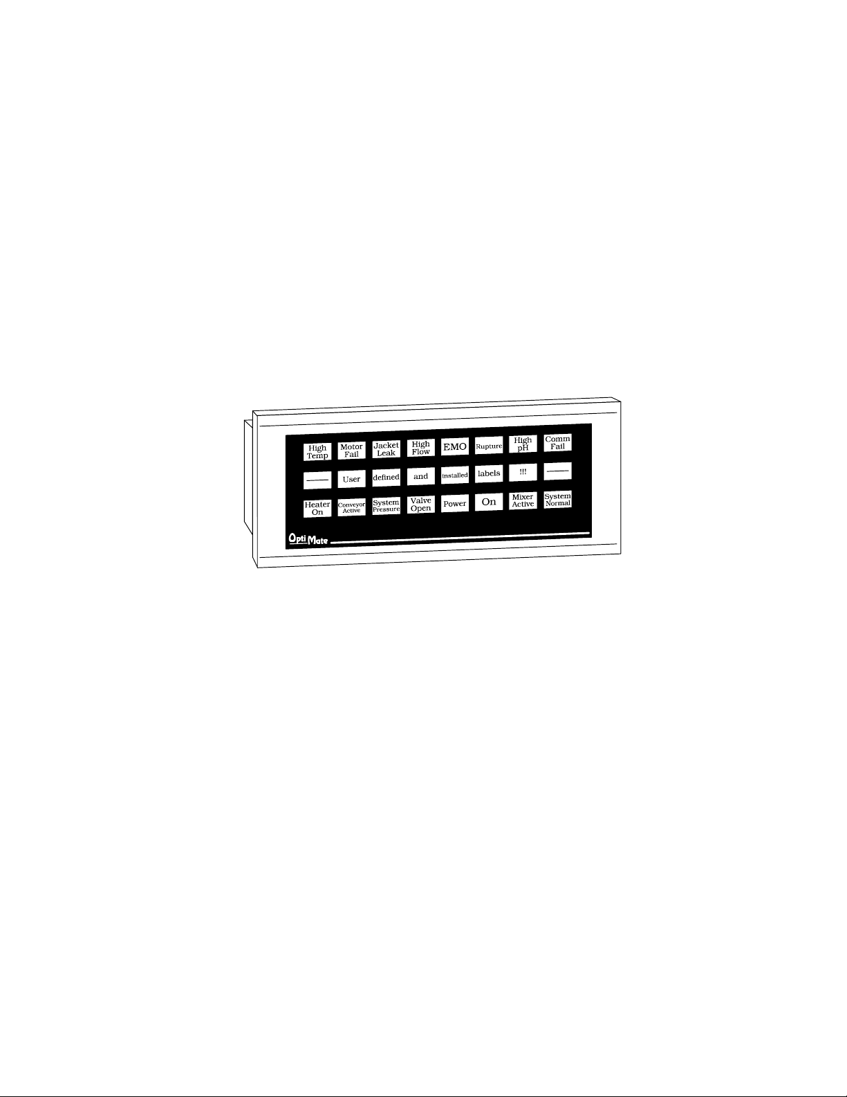
OP--1212
Pushbutton Panel
In This Manual....
— Getting Started
— Preparing the Labels
— Installing the Panel
— Applying Ladder Logic
1
Page 8
2
Getting Started
Getting Started
The Purpose of
this Manual
Configuration
Software
This manual shows you how to install, operate and maintain the OP-1212 Lamp
Pushbutton Panel. It includes wiring diagrams and power requirements, as well as
the information you need for selecting the proper connecting cables.
All OptiMate panels are configured using
the OptiMate OP--WINEDIT
configuration software.
OP--WINEDIT software is compatible
with computers running
Windows 95/98/2000/NT/XP.
OP--WINEDIT is ordered as a separate
item from the OptiMate panel from
AutomationDirect.
The software is loaded onto your
personal computer and simple follow the
setup instructions in the supplied user
manual and the built--in HELP screens.
The software allows setup of y our
complete application, including the type
of PLC being used.
Note that OP--WINEDIT is also used to
configure the OP--9001,
Communications Master panel. The
software can be used with Allen--Bradley
PLCs.
Supplemental
Manuals
Technical
Assistance
There are several other manuals you will find helpful or necessary:
D Respective PLC User Manual for the PLC(s) you are using with the OptiMate
panel.
D OP--9001--M Communications Master User Manual provides details of how to
use the OP-9001 for connecting multiple OP-Panels to a single CPU.
D DirectSOFTt User Manual--Shows you how to use the DirectSOFT
Windows software to write your ladder logic for DirectLOGICt PLCs.
If you are not successful with implementing the information in this manual, you may
call AutomationDirect technical support at (800) 633-0405, Monday through Friday
from 9:00 A.M. to 6:00 P.M. Eastern Standard Time. The technical support team will
work with you to answer your application questions. If you have a comment or
question about our products, services, or manuals which we provide, please fill out
and return the suggestions card included with this manual.
Page 9
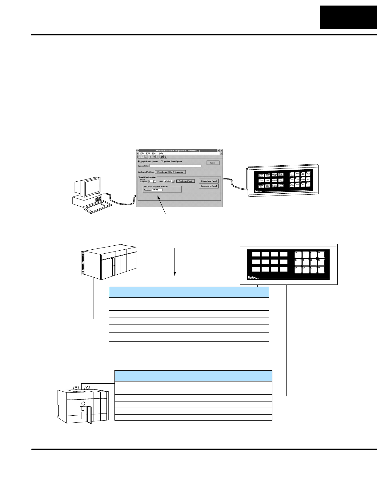
Getting Started
33
How the OP-1212
Works
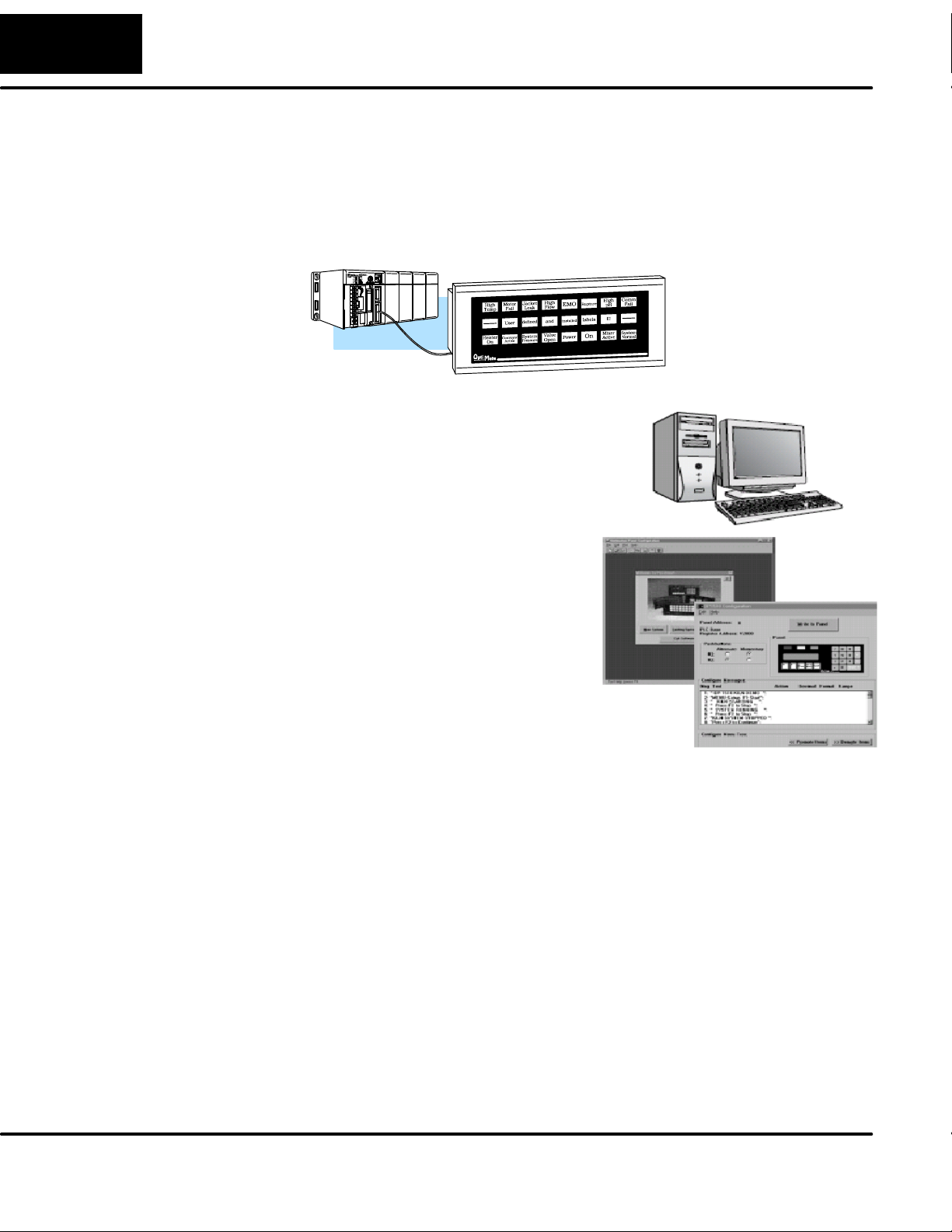
AutomationDirect
The purpose of the panel is to provide you with both pushbuttons (12) and lamps (12)
so that you can have status and control functions that will work with your PLC. An
additional benefit of this panel is found in the LEDs that are in the upper left hand
corner of each pushbutton. These LEDs can operate as indicators to reflect the
status of the individual pushbutton, or they can operate independent of the
pushbutton status. The LEDS can turn ON or OFF and even flash for added
attention.
To link the pushbuttons, LEDs, and lamps to your PLC, the OP-1212 uses a
technique called “memory mapping”. This technique ties the pushbuttons, LEDs,
and lamps to specific reserved areas of memory in the PLC. You can use any
available memory as long as it is consecutive.
The base register address is entered during configuration using the OPWinEdit
software. Each of the functions for the pushbuttons, LEDs, and lamps are
controlled by the status of their assigned bits within the memory words that you
have reserved. You interface these words of memory through your ladder logic.
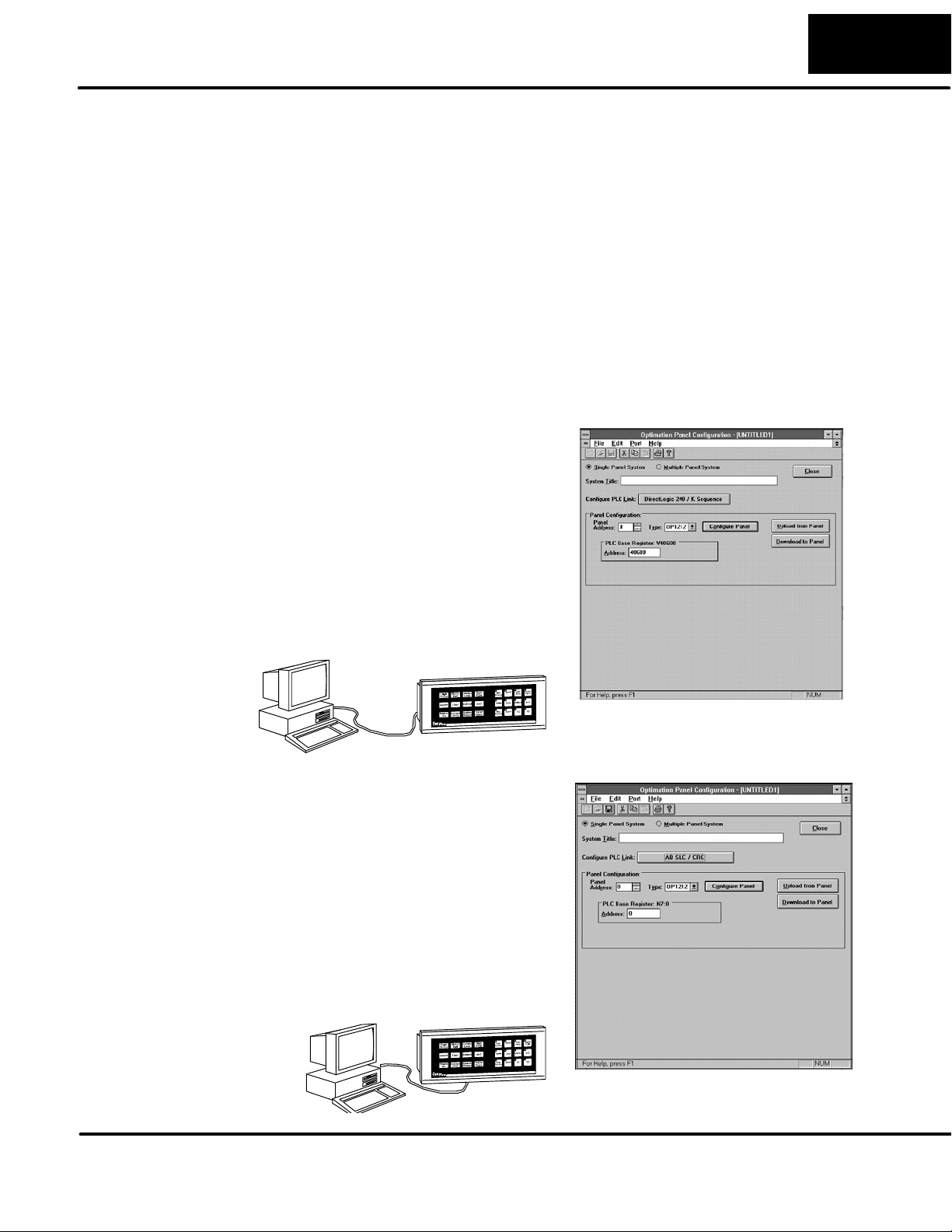
Prior to connecting the OP-1212 to
your PLC, load the OP--WINEDIT
configuration software onto your
personal computer, and begin to
define how you want to use the
functions that have been designed
into the panel. Among other
decisions, you are prompted to fill in
a base register address. In the
example we have shown here, we
have used V40600 as the start of
the mapped memory addresses.
Allen-Bradley
The same OP--WINEDIT
configuration software used for the
AutomationDirect product is also
used for the Allen-Bradley product.
As you move through the screens,
one of the key items you complete
is the base register address for
storing data relative to the
pushbuttons. In the example, we
have used N7:0 as the start of the
mapped memory addresses. This
means the PLC file number is 7 and
the base address is 0.
Page 10
4
Getting Started
Using the Pushbutton Panel...5 Easy Steps
Step 1: Prepare
Your Labels
(Pages 5--6)
Step 2: Install the
Panel
(Pages 7--14)
Step 3: Use
OP--WINEDIT
Software
First, you need to prepare the labels for each of
the pushbuttons and lamps. The labels insert
into plastic sleeves behind the main cover. To
access the sleeve, you merely snap loose the
front bezel.
Preparing for installation, you will want to
check the individual specifications. These
include dimensions, power requirements,
cabling requirements, and NEMA ratings.
We include information you will need for
mounting; i.e. cutout dimensions, cabling
requirements, components needed, etc.
You will need the OP--WINEDIT configuration
software in order to configure the panel and
PLC. OP--WINEDIT is ordered as a separate
item from the OptiMate panel from
AutomationDirect.
The software is used for both DirectLOGIC
and Allen--Bradley PLCs.
Cables
External Power
Step 4: Configure
the Panel to Work
with your PLC
(Pages 15)
Step 5: Write the
Ladder Logic
(Pages 19--31)
After setting a DIP switch on the rear of the panel
and attaching the programming cable, you are
ready to configure your panel. The simple and
easy-to-follow screens make configuration a
painless process.
The amount of ladder logic programming
knowledge you need is very basic. In most
cases, you are already familiar with the
elements of logic that are required. We’ll
give you examples in the final section of
this manual, and you will see right away
just how easy it is.
C100
C101
Y10
OUT
Y11
OUT
DIP
Switch
Page 11
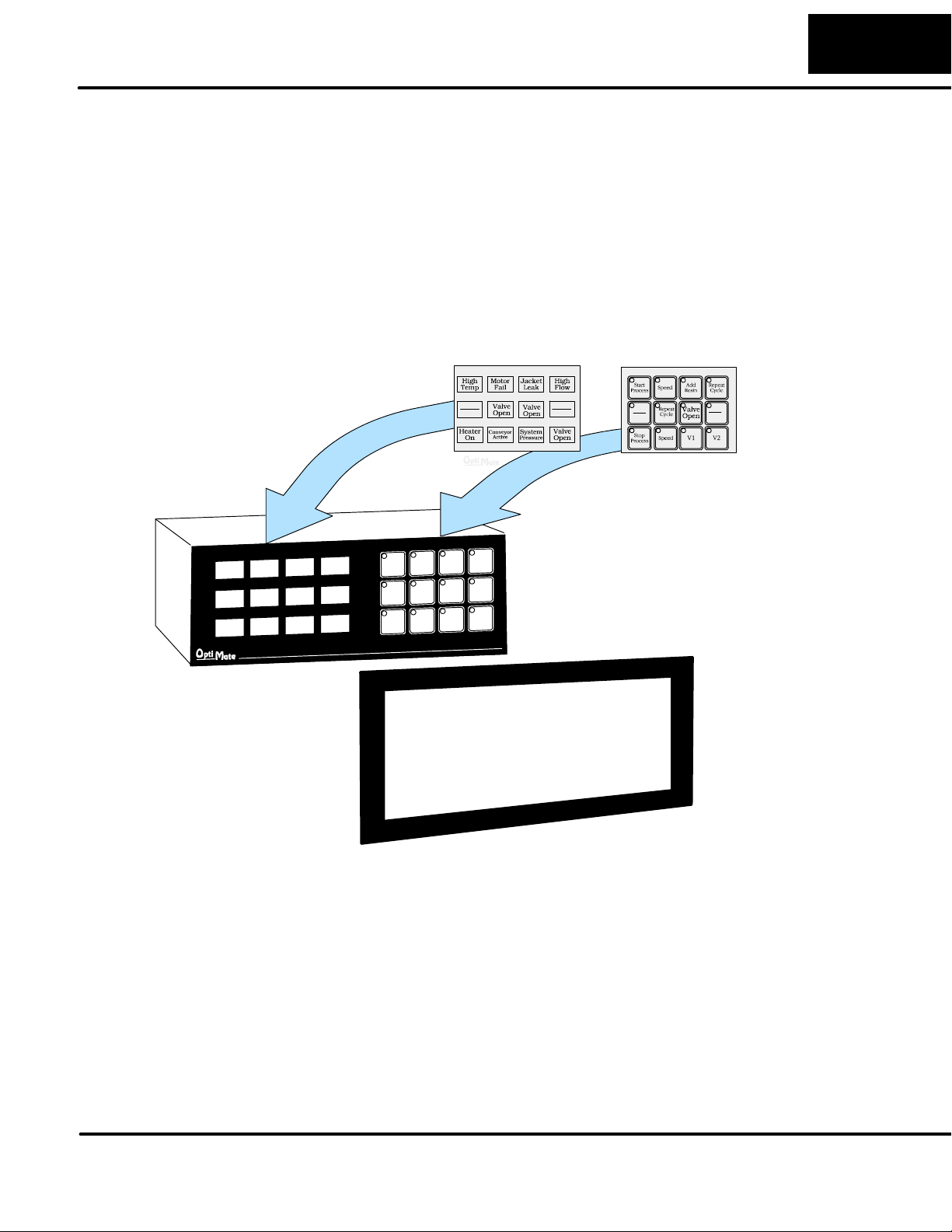
Preparing the Labels
5
Preparing the Labels
Applying Text to
Each Label
Insert legend between window
frame and cabinet
Preparing the labels for the OP--1212 panel requires you to slide a legend
transparency into two pockets in the panel overlay. Use the following procedure:
1. Remove the bezel from the module by unsnapping the four tangs that hold the
bezel to the module frame.
2. Create a legend transparency. There are several ways of doing this. A template is
provided on the next page that gives you the available dimensions. The nicest
legends result from using a computer graphics program and a laser printer to
create the transparency.
Finished Legend
Window Frame
Bezel
3. Slide the finished legend into the pocket space between the window frame and
LED bars.
4. Re--attach the bezel by snapping the bezel onto the case.
Page 12
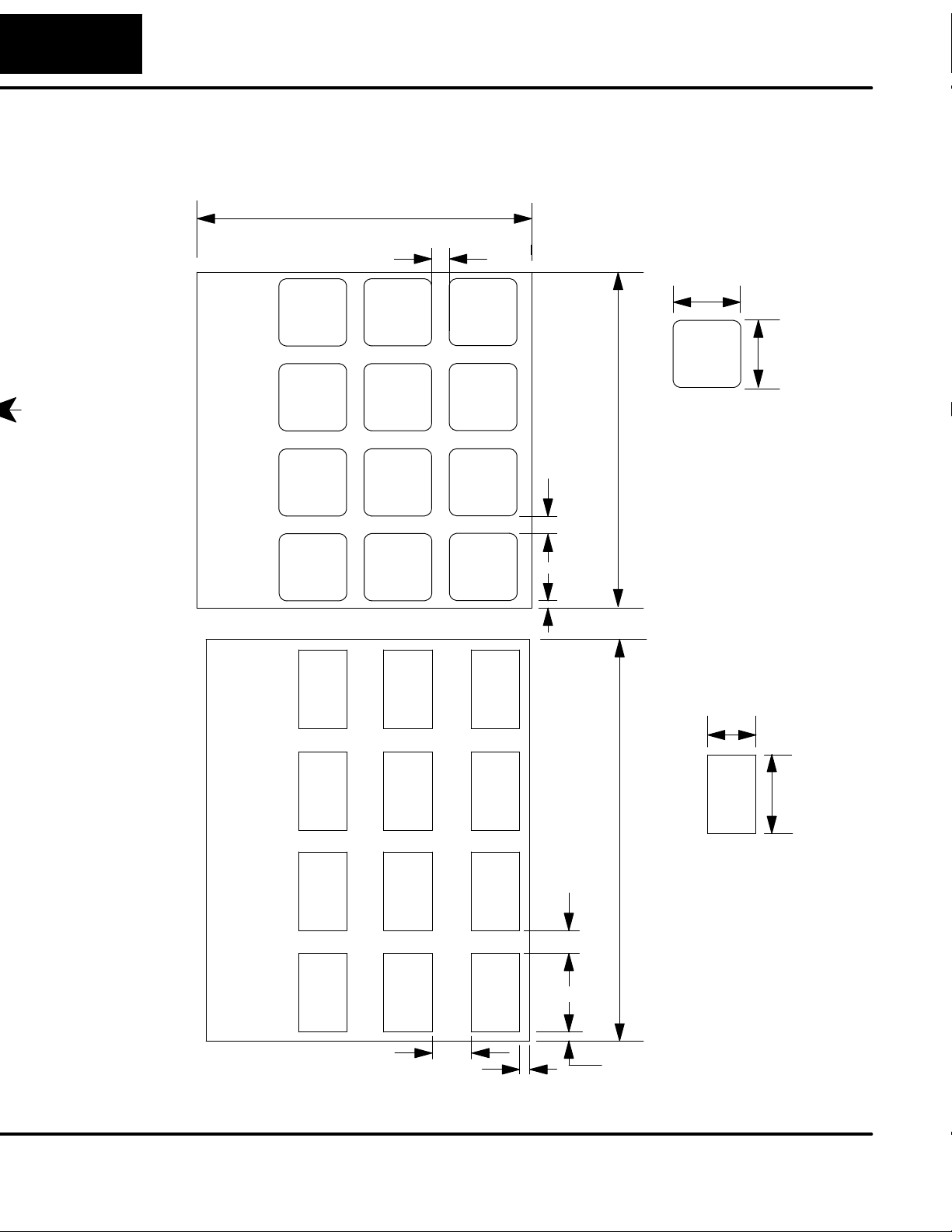
6
Preparing the Labels
Template for Creating Labels
3.00
Dimensions in Inches
0.15
0.60
0.60
3.00
0.15
0.07
0.35
0.40
0.70
3.60
0.20
0.10
0.10
Page 13

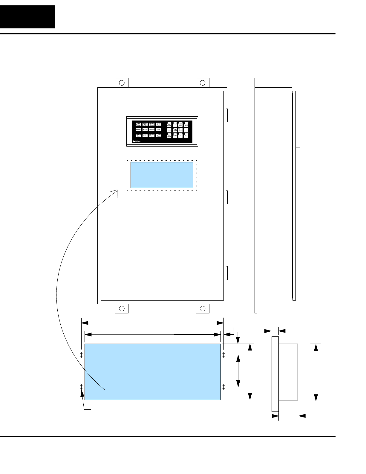
Installing the Panel
In this section you will be given all of the information you need to install the panel.
Before actually installing the OP-1212 panel, it may be helpful to examine the
specifications and make sure that the requirements of your application are met.
Panel Specifications:
7
Installing the Panel
Physical
Specifications
Environmental
Specifications
Operating
Specifications
Weight 18 ounces...............................
Panel Fasteners Four 6x32 threaded studs.......................
NEMA Rating NEMA 4..........................
Operating Temperature 0° to 50° C.................
Storage Temperature --20° to 80° C...................
Operating Humidity 5 to 95% (non-condensing).....................
Air Composition No corrosive gases permitted........................
Power Budget Requirement 7 VA @ 8 -- 30 VDC.............
570 mA @ 12 VDC (all Lamps and
LEDs ON)
285 mA @ 24 VDC (all Lamps and
LEDs ON)
Power Connector Removable Terminal Block......................
2 position
Absolute Maximum Voltage 32 VDC..............
Diagnostics Power On, CPU...........................
Communication Link RS232 or RS422....................
4800, 9600 and 19200* baud
15 pin female D type connector
*Only 4800 and 9600 baud will work
with Allen-Bradley PLCs.
Page 14
8
Installing the Panel
Dimensions for Mounting
Cutout Area
Example panel mounting
8.85
8.40
0.23
0.75
2.00
3.50
0.5
3.50
0.16 DIA
Dimensions in Inches
1.75
Page 15
Power and Cabling Requirements
9
Installing the Panel
What Are Your
Application
Needs?
1. Point-to-Point
A single cable connection
from the PLC to the panel
gives you access to the
PLC’s data registers and
ladder logic.
Your communication cable requirements depends on your particular application.
There are two types of configuration possibilities: point-to-point (a single operator
interface connected to a PLC) and multi-drop (multiple operator interfaces
connected to a PLC).
D Point-to-Point -- If you only need one operator interface connected to one
PLC, then choose the appropriate cables from the chart on page 11.
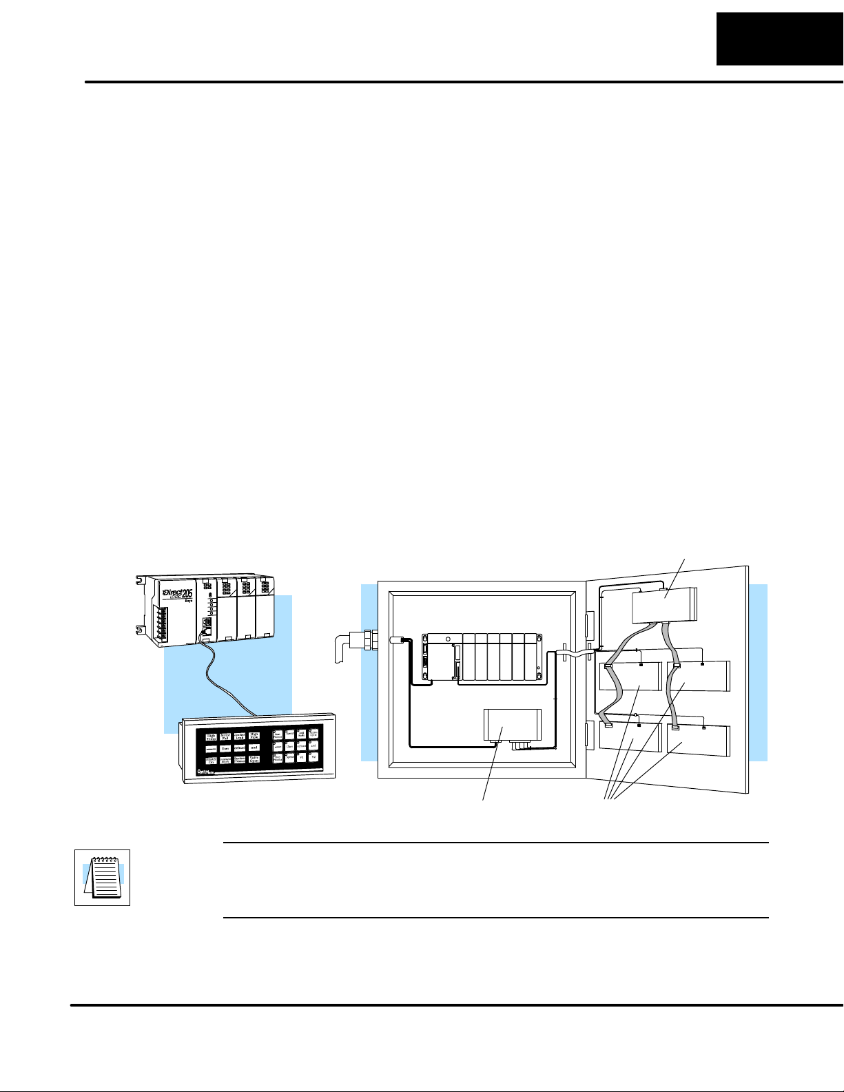
D Multi-drop -- By using an OptiMate OP--9001 Communications Master,
multiple Optimate units can be connected to a single PLC. Up to 31 individual
units can be connected in a daisy-chain fashion to the OP--9001.
Communications are via RS422 between the OP--9001 and the operator
interfaces. When using a quality shielded cable, a total distance of up to 4000
feet between the OP--9001 and the last operator interface unit in the chain
can be achieved. If the distance is 30 feet or less, a ribbon cable with
easy-to-install crimp-on ribbon connectors can be used.
2. Multi-drop
Multiple OP-panels can be interfaced to a single PLC.
This requires the use of the OP-9001 Communications
Master. With the Communication Master, up to 31
panels can be interfaced to a single CPU port. Each can
be programmed for entirely different functions. Panels
can be distributed up to 4000 feet* from the OP-9001.
OP-9001
Power
Source
*NOTE: Please read and follow the cabling requirements in the OP-9001 User
Manual (OP-9001-M) when using multiple panels. Failure to follow the guidelines of
the User Manual may affect the integrity of the RS422 link, resulting in
communication errors.
DL405 CPU Base
Power Supply OP-panels
Page 16

10
Programming
Cable
Installing the Panel
The diagrams shown below give the connector specifications including the pinouts
for each end of the available connecting cables.
The OP-ACBL--1 is used to connect your OP-1212 panel to your computer for
programming.
This cable must be used to configure the panel.
Computer
OP-ACBL--1
Panel
DB9 DB15
33
7
8
PLC to Panel Cable
5= 0V
4= not used
3= Dout
22
2= Din
55
1= not used
The OP-ACBL--1 (shown above) is also used to connect Allen-Bradley SLC 5/03 and
5/04 PLCs
DirectLOGIC PLCs, the cabling requirements will vary depending on the PLC type
being used. Refer to the table on the next page for matching the proper cable to your
PLC. Pin diagrams refer to the ends of the cables and not the communication ports.
9
9=not used
8= CTS
7= RTS
6=not used
1
9 = not used
10= not used
11 = not used
12= not used
13= not used
14= not used
15= not used
15
1
1= not used
2= Dout
3= Din
4= not used
5= 0V
6= not used
7= not used
8= not used
to an OP-1212 panel. Since the OP-1212 is compatible with all of the
Page 17

Installing the Panel
See the next page for matching your PLC to the correct cable.
11
RJ12 (PLC) DB15
43
15-pin (PLC)
23
4
5
RJ11 (PLC)
23
DB15 (PLC)
23
13
14
15
1
7
8
DB25 (PLC)
23
4
5
8 Pin Mini DIN
73
23
51
DB15
23
57
DB15
21
54
DB15
23
54
DB15
23
57
DB15
24
52
1= 0V
2= not used
3= Din
4= Dout
5= not used
6= not used
8= not used
7= 0V
6= not used
5= CTS
4= RTS
3= RXD
2= TXD
1= Din
2= Dout
3= not used
4= 0V
8= YOM
7= CTS
6= not used
5= not used
4= On-line
3= Din
2= Dout
1= YOP
13= not used
12= not used
11 = not used
10= not used
9= not used
8= not used
7= 0V
6= not used
5= CTS
4= RTS
3= Din
2= Dout
1= not used
RS422 Pinout
PLC
Din +
Din -Dout +
Dout --
0V =0V
RTS+
CTS+
RTS-CTS--
11
12
9
10
5
PLC
Panel
= Dout+
= Dout -= Din +
= Din--
RJ11
1
3
RJ12
345621
1234
1
7168
4
2
15= not used
14= not used
13= not used
12= not used
11 = not used
10= not used
9= not used
15
15= tied (0V)
14= tied (0V)
13= tied (0V)
12= not used
11 = not used
10= not used
9= not used
25= not used
25
24= not used
23= not used
22= not used
21= not used
20= not used
19= not used
18= not used
17= not used
16= not used
15= not used
14= not used
5
RJ12
O P -- 2 C B L -- 1
OP-2CBL
15-pin
OP-3CBL
RJ1 1 DB15
OP-4CBL--1
DB15
OP-4CBL--2
OP-ACBL--2
Mini--DIN
Panel
1
9= not used
10= not used
11 = not used
12= not used
13= not used
14= not used
15= not used
15
1= not used
2= Dout
3=Din
4= not used
5= 0V
6= not used
7= not used
8= not used
DB15
DB15
DB15
DB15DB25
DB15
Page 18

12
Fami
l
CPU
P
Cab
l
DL05:D
0--0
DL0
6:D
0--0
6
D
i
D
2--240
DirectLOGIC
D
i
DirectLOGIC
D
3--340
D
3--350
D
3
0
D
0
DL405
Installing the Panel
Choosing the Proper Connecting Cables
OptiMate Panel Cables
Depending on which PLC you are
using, you may require as many
as two cables--one to connect the
panel to a personal computer for
configuration; and one to
connect the panel to the PLC.
Here are the requirements:
D OP-ACBL-1: all units require this
cable for configuration. This isa 9-pin
male to 15-pin male cable that
connects your personal computer to
the OptiMate unit. (This cable is also
used to connect an OptiMate panel to
the Allen-Bradley SLC--500 PLC.
D CPU Cables: You will also need the
appropriate cable to connect your
CPU to the OptiMate unit. Use the
chart shown to the right to choose the
correct communications cable.
D OP-ACBL-2: The8PinMini--DINisa
non standard connector used for the
Micrologix 1000. We recommend
using the OP- -ACBL--2 cable and
modifying the length for any
applications between 6.56 - - 50 ft.
OP--9001 Cable Connectors
If you’re planning to use multiple
panels and an OP--9001, then
you’ll need to build your own
custom cables. Since the proper
cable choice really depends on
your application, we offer the
following connectors.
D OP--CMCON--1 — pack of 4 ribbon
cable connectors.
D OP--CMCON--2 — pack of 4
solder-type connectors
For electrically noisy environments,
we recommend a good shielded
cable, such as Belden 9729 or
equivalent. This type of cable will
require the solder-type connectors.
If you’re going 30 feet or less, you
can use ribbon cable. For ribbon
cable, we recommend Belden
9L28015 or 3M 3365/15. See
Page 14 for more information.
.
OptiMate Cables
y
DirectLOGIC
DL05
DirectLOGIC
DL06
DirectLOGIC
DL105
rectLOGIC
DL205
rectLOGIC
DL305
DirectLOGIC
DL405
GE®Series 1 IC610CPU105, 106 Requires DCU* OP-4CBL--2
GE®Series
90/30
GE®Fanuct
Series 90 Micro
MODICON ModBus RS45 OP--MCBL--1
* requires RS232 Data Communications Unit (D3--232--DCU)
** also DC versions
DL105: F1--130 One port (RJ12) OP--2CBL
D2--230 One port (RJ12) OP--2CBL
D2--250--1 Top port (RJ12) OP--2CBL
D2--260
D2--DCM (module) Only one (25 pin) O P -- 4 C B L -- 2
D3--330 Requires DCU* O P -- 4 C B L -- 2
D3--330P Requires DCU* OP-4CBL--2
4-- 4
4-- 44
D4--450
D4--DCM (module) One port (25-pin) OP-4CBL--2
Slice I/O panels One port (15-pin) OP-4CBL--1
All models (311--351) RS422 serial port Not available
All models RS422 serial port Not available
CPU
(or other device)
5
ort
Port 1 (RJ12) OP-2CBL
Port 2 (RJ12) OP-2CBL
Port 1 (RJ12) OP-2CBL
Port 2 (15 pin) OP-2CBL--1
Top port (RJ12) OP--2CBL
Bottom port (RJ12) OP--2CBL
Bottom port (15 pin) O P -- 2 C B L -- 1
Top port (RJ11) OP-3CBL
Bottom port (RJ11) OP-3CBL
Top port OP-2CBL
Bottom port OP-4CBL--2
Top port (15-pin) OP-4CBL--1
Bottom port (25-pin) OP-4CBL--2
Top port (15-pin) OP-4CBL--1
Bottom port (25-pin) OP-4CBL--2
Phone Jack (RJ12) OP-2CBL
Top port (15-pin) OP-4CBL--1
Bottom port (25-pin) OP-4CBL--2
e
Page 19

OptiMate Cables (cont’d)
Fami
lyCPU
P
Cab
l
SIMATIC
®
TI305
3
3
PPX:3
3
3
0--CPU,PPX:43
0--CPU
SIMATIC
®
TI40543
CPU,PPX:43
CPU**
CPU
(or other device)
325--07, PPX:325--07 Requires DCU* OP-4CBL--2
330--37, PPX:330--37 Requires DCU* OP-4CBL--2
TI305t /
TI305t
TI405t /
TI405t
Allen-Bradley
SLC500
Allen--Bradley Micrologix1000/1200/1500
®
®
325S--07 (or 325 w/ Stage Kt) Requires DCU* OP-4CBL--2
330S--37, PPX:330S--37 Requires DCU* OP-4CBL--2
5--37,
425--CPU, PPX:425--CPU ** One port (15-pin) OP-CBL--1
4
5--
Smart Slicet I/O panels
5/03
5/04
5--37
5--
Installing the Panel
ort
Phone Jacks (RJ11) OP-3CBL
If DCU is used* OP-4CBL--2
Top port (15-pin) OP-4CBL--1
Bottom port (25-pin) OP-4CBL--2
Top port (15-pin) OP-4CBL--1
Bottom port (25-pin) OP-4CBL--2
One port (15-pin) OP-4CBL--1
Bottom port OP-ACBL--1
One port (8--pin Mini
Din)
OP-ACBL--2
e
13
* requires RS232 Data Communications Unit (D3--232--DCU)
** also DC versions
Page 20

14
Installing the Panel
Connecting a Power Supply
Power Supply
Connections
The OP-1212 panel can operate on DC voltages between 8 and 30 VDC rated at 7
watts. Connect the panel to a power supply (within the required voltage range and
wattage) using the terminal block connector supplied. The connector is polarized to
prevent reversing the connections. The male receptacle on the rear of the panel will
only connect in one way with the female connector that is supplied with your
OP-1212 panel. Pin 1 is the positive connection, while Pin 2 is the negative, or
ground, connection.
You must use an external power supply that
can deliver voltages in the 8 to 30 VDC
range, and can supply 7 watts of power.
A two-prong male connector is on the rear of
the unit. Your OP-panel is
shipped with the female
connector.
Install the female connector to
a cable for attachment to your
power supply.
+
GND
Model
OP-1212 240mA (all Lamps and LEDs OFF)
NOTE: Consult our catalog or website, www.automationdirect.com, to purchase a power
supply.
Current Consumed at 12VDC
570mA (all Lamps and LEDs ON)
Current Consumed at 24VDC
120mA (all Lamps and LEDs OFF)
285 mA (all Lamps and LEDs ON)
Page 21

Installing the Panel
Connecting the Panel to your Personal Computer
15
Assigning an
Address to the
OP-1212
How to Set the
Address
A 6-position DIP switch on the rear of the OP-1212 is used to assign a hardware
address to the panel. Each panel must have a unique address. Any address
between0 and 30canbe used when communicatingbetweenapanel and a PLC
or the OP-9001 Master Communications panel. Address 31, however, is
reserved. See the note that follows.
NOTE: You must use Address No. 31 when you are configuring your OP-1212 panel.
No other address will work for the configuration process. In a similar manner, if you
are connecting more that one OP-panel to a single CPU (through an OP-9001), then
the OP-9001 needs to know which set of configuration parameters belong to which
OP-panel. You do this by assigning an address in the range of 0 to 30 to each panel
connected. Each panel must have a different address.
DIP Switch
Rear View
To set the address on the OP-1212, set the apppropriate switches on the dip switch
to the desired address. The figure below shows the binary weighting of each switch
position. Notice that it is in decimal format. To select address 14 for example, press
switches 2, 3 and 4 to the right, and switches 1, 3 and 5 to the left (2 + 4+ 8 = 14). Any
address between 0 and 30 is valid for the OptiMate-to-CPU (or to OP9001)
communications. Address 31, however selects the configuration mode. Use this
mode when you connect your personal computer to the panel for configuration. To
select address 31, turn switches 1 through 5 ON.
The Termination
Resistor
NOTE: Please note that when the dip switches are changed, the OP-1212 must be
power cycled before the new settings will take effect.
123456
Switch
On
Switch position 6 enables or disables an internal termination resistor. The OptiMate
panels communicate via an RS232 or RS422 communcations network. If a single
panel is used located less than 50 feet from the PLC, use RS232 communication
then a termination resistor will not be required (i.e. switch position 6 is turned OFF).
If a panel will be located more than 50 feet from the PLC or multiple panels are used,
RS422 must be used. For single panel installations, this means that switch 6 must
be enabled (ON). For multi-drop installations, this means the last panel only must
have switch 6 enabled (ON). All other panels must have switch 6 disabled (OFF). A
more detailed description of multiple panel installations is given in the OP-9001-M
User Manual.
Switch Position
Address Value
ON = ENABLE OFF = DISABLE
123456
12 4 816T
Termination
Resistor.
(See text
below.)
Page 22

16
Installing the Panel
Using the OP-9001 to Connect Multiple Panels
With the addition of the OP-9001 Communications Master panel, you can connect
up to 31 panels per a useable CPU port of the PLC. Shown below are the connection
requirements. For specifics of the OP-9001 panel itself, please refer to the
Communications Master User Manual (OP-9001--M).
NOTE: The OP-9001 must be used in a multiple panel configuration.
Ribbon cable with DB15 male connectors attached. Panels can be connected directly to the
OP-9001 ports or be daisy-chained to other OPpanels.
Power
Source
PLC
OP-9001
Power supply receptacle. Same as the one
on the OP-1212. See
Page 12.
Belden 9279 Specifications
No. twisted pairs
Nom. Impedance (ohms)2100
Nom. Capacitance (pF/m) 41.0
Wire Gauge (AWG) 24
NOTE: Panels can be located as far away as 4000 feet from the OP-9001 when
using shielded cable (Belden 9729 or equivalent). Flat ribbon connections can be
used for a distance of 30 feet maximum. For ribbon cable, we recommend Belden
9L28015 or 3M 3365/15.
Power Supply
OP-panels
Configuration
Jumper
LED
DB15 for connecting to the PLC.
See chart on Page 11 for selection of the proper cable.
Two DB15 ports for RS422 connection to any OP-panel.
LED
Page 23

Understanding the OP-1212
Understanding the OP-1212 Panel
17
Overview
Memory Mapping
The OP-1212 Lamp/Pushbutton panel provides various features and options that
can be used together or stand alone with your logic program. The link to the PLC is
one of the important aspects of the configuration process. Part of this link is called
“memory mapping”. Once the panel has been mapped and configured correctly, you
will be able to use the many functions the OP-1212 provides. This section will
discuss the functions and get you more familiar with the panel itself before showing
the actual configuration and programming examples.
Memory mapping is a technique that tells the panel what part of the PLC memory you
want to use. These memory areas are frequently referred to as registers. Once you
have selected a memory address, you will be able to manipulate the data via your
ladder logic program. The OP-1212 will occupy a bank of 6 contiguous registers as
illustrated in thetables below.In the first table, m+0 represents the first register of the
bank of memory required for mapping the OP-1212. This can be any address in your
PLC that can be used for data storage. The second table shows the bit orientation for
each panel feature. These mapping assignments will be the same for any PLC type,
the only difference being the address location selected for mapping. The information
for specific PLC types will be discussed in the Applying Ladder Logic section.
LSBMSB
123456789101112
m+0
123456789101112
m+1
123456789101112
m+2
123456789101112
m+3
123456789101112
M3
M2M1
m+4
123456789101112
m+5
Indicator Lamp
Indicator Lamp Flash
Button LEDs ON/OFF
Button LEDs Flash
Button ON/OFF
ForceData&Comm
Pushbuttons
Lamps
The 12 pushbuttons on the OP-1212 panel provide a means of control for any
process connected to your PLC. The pushbuttons can be configured as either
momentary or maintained (also called alternate). The momentary pushbuttons
remain ON for as long as you are manually pressing them while the maintained will
change status every time you press them. You can select either operation for each
pushbuttons when you are configuring the panel. When the PLC and panel are
properly mapped, the pushbuttons are used just like relay contacts. If you refer to the
table above, the pushbuttons status will be determined by the status of the bits in the
m+4 memory register.
There are 12 Lamps available on the OP-1212 panethat are arranged in 3 rows of
four.The panel is shipped with all red Lamps, however, you can order additional red,
green, and yellow packs of lamps for more customized arrangements. Refer to our
catalog for the lamp kit part numbers and prices.
After the PLC and panel have been properly mapped, the lamps can be activated
bywritinga1toitsassociatedbitinthem+0 address location. The bit is turned
on via your ladder logic usually through activation of a contact. The contact c an
also be one of the 12 pushbuttons on the OP-1212 panel. We will provide
examples of these applications in the Applying Ladder Logic Section of this
manual.
Page 24

18
Understanding the OP - 1212
Flashing the
Lamps
LEDs and
Separation Mode
Flashing the LEDs
Force Functions
Another feature of the Lamps is there ability to flash. This feature is also controlled
via your ladder logic. The flashing feature requires that the lamp is activated first,
then the corresponding bit in memory location m+1 is activated. Again, this
accomplished by activating a coil.
Each of the 12 pushbuttons on the OP-1212 have corresponding LEDs located on
the upper left hand corner. The LEDs are usually used as an indication of the
pushbutton status however, they can be configured to work independently. When
configuring the OP-1212 panel, you have the option to select LED separation
mode. If this option is selected, the LEDs will work in the same manner as the Lamps
using the ladder logic to control the status of the LED. Also, the pushbutton itself
must be configured as a momentary pushbutton. To activate an LED in this
configuration, the appropriate bit in memory location m+2 must be energized.
Just like the Lamps, the LEDs have the ability to flash. This feature is also controlled
via your ladder logic. The flashing feature requires that the LED is activated first
(memory location m+2), then the corresponding bit in memory location m+3 is
activated. Again, this is accomplished by activating a coil. As mentioned previously,
the LED is used for the status of its associated pushbutton unless it is configured for
LED separation mode. This also applies to flashing the LEDs independently of the
pushbuttons.
The OP-1212 has the capability to “force” a pushbutton ON or OFF through your
ladder logic. For example, you might have a pushbutton that starts a process, and
you want to turn it off after the process has completed. Pressing the pushbutton
would start the process (turns the pushbutton ON) and the ladder logic would turn
the pushbutton OFF after the process was complete. Since the pushbuttons must
be configured as maintained (alternate) for the force function to work, the process
would be halted until the pushbutton was activated again. The force function feature
and pushbutton option is enabled during the configuration of the panel.
There are three modes of force function available which are located in the three
most significant bits of memory location m+5.
Mode 1 (M1)-forces all Pushbuttons to reflect the status stored in m+5. For
example, the data shown below would force Pushbuttons 3, 4 and 12 to ON and all
the others would be forced OFF.Notice that bit M1 of m+5 is setto 1 for this mode. M2
and M3 are set to 0’s.
Mode 2 (M2)-forces ON only those Pushbuttons matching the bits set in
register m+5. The bits not set do not affect the status of the Pushbuttons. You would
set M2 to 1 while M1 and M3 are set to 0.
Mode 3 (M3)-forces OFF only those Pushbuttons matching the bits set in
register m+5. The bits not set do not affect the status of the Pushbuttons. You would
set M3 to 1 while M1 and M2 are set to 0.
Force Function
M2M1 M3
Registers
NOTE: Forcing is similar to a one-shot process. That is, once you have set the mode
123456789101112
1100000000010001
m+5
pushbutton number
in m+5, the bit patterns in m+4 are changed (according to the mode selected), and
then, all of the bits in m+5 are set to zero
. What this means is that all pushbuttons
return to normal manual operation after the forcing is completed.
Page 25
Applying Ladder Logic
General Concepts
19
Applying Ladder Logic
Memory Mapping
PC
DirectLOGIC
The OP-1212 uses memory mapping in order to link itself to a PLC. Memory
mapping is a technique that maps the memory of the OP-1212 to the memory of the
PLC. During initial c onfiguration, the beginning address must be selected in the PLC
memory where the mapping process will start. By knowing where the data of the
specific panel is mapped, this data can be moved, changed or monitored using
ladder logic.
During configuration, you determine the starting address
for the memory mapping process.
1234
567
9101112
8
1234
5678
9101112
Mapping Assignments
Allen-Bradley
Mapped Memory Location
m+0 (such as V40600) C0-C17
m+1 (such as V40601) C20-C37
m+2 (such as V40602) C40-C57
m+3 (such as V40603) C60-C77
m+4 (such as V40604) C100-C117
m+5 (such as V40605) C120-C137
Mapped Memory Location
m+0 (such as N7: 0/0--0/15)
m+1 (such as N7: 1/0--1/15)
m+2 (such as N7: 2/0--2/15)
m+3 (such as N7: 3/0--3/15)
m+4 (such as N7: 4/0--4/15)
m+5 (such as N7: 5/0--5/15)
Function
Indicator Lamps ON/OFF
Indicator Lamps Flash Control
Button LEDs ON/OFF
Button LEDs Flash Control
Button ON/OFF Status
Force Pushbuttons Data & Comnd
Function
Indicator Lamps ON/OFF
Indicator Lamps Flash Control
Button LEDs ON/OFF
Button LEDs Flash Control
Button ON/OFF Status
Force Pushbuttons Data & Comnd
The pushbuttons
and lamps are
numbered left to
right starting in
the upper left
corner of their
respective area.
Page 26

20
Applying Ladder Logic
Addressing
Conventions
DL05, DL06,
DL105, DL205
or DL405
DL305
Before going into ladder logic programming, it is good to take a moment to review
and compare the addressing conventions used by AutomationDirect and
Allen-Bradley.
DirectLOGIC Memory -- A typical address within a DirectLOGIC PLC is Vxxxx,
such as V40600 for DirectLOGIC PLCs (DL05, DL06, DL105, DL205, DL350 and
DL405 families) and Rxx, such as R16 for the DL305 family. The V-memory in the
DirectLOGIC PLCs is divided into 16-bit registers, and the R-memory in the DL305
is divided into 8-bit registers. Refer to your individual User Manuals for complete
memory information. The two diagrams below shows how the OP-1212 could be
mapped during configuration. In this example, V40600 and R16 have been chosen
as starting registers to map the OP-1212 to the PLC, but it could actually be any
available user or internal relay memory areas as long as they are consecutive:
0123456789101112131415 bit
V40600
V40601
V40602
V40603
V40604
V40605
01234567
R16
R20
R22
R24
R26
R30
Indicator Lamp ON/OFF
Indicator Lamp Flash
Button LEDs ON/OFF
Button LEDs Flash
Button ON/OFF
ForceData&Comm
Indicator Lamp ON/OFF
Indicator Lamp Flash
Button LEDs ON/OFF
Button LEDs Flash
Button ON/OFF
ForceData&Comm
bit
12 11 10 9
12 11 10 9
12 11 10 9
12 11 10 9
12 11 10 9
12 11 10 9M1M2M3
12 11 10 9 8 7 6 5 4 3 2 1
12 11 10 9 8 7 6 5 4 3 2 1
12 11 10 9 8 7 6 5 4 3 2 1
12 11 10 9 8 7 6 5 4 3 2 1
12 11 10 9 8 7 6 5 4 3 2 1
12 11 10 9 8 7 6 5 4 3 2 1M1M2M3
01234567
R17
R21
R23
R25
R27
R31
8 7 6 5 4 3 2 1
8 7 6 5 4 3 2 1
8 7 6 5 4 3 2 1
8 7 6 5 4 3 2 1
8 7 6 5 4 3 2 1
8 7 6 5 4 3 2 1
After the address has been selected and mapped, it will allow the ladder logic to treat
pushbuttons as contacts and Lamps, and LEDs as coils. The following table is an
example of the control relay correlation for DirectLOGIC PLCs to the OP-1212 when
the address is configured for V40600. Use the work sheet in Appendix A for your
application.
Device Lamp
ON/OFF
1
2
3
4
5
6
7
8
9
10
11
12
M3
M2
M1
C0 C20 C40 C60 C100 C120
C1 C21 C41 C61 C101 C121
C2 C22 C42 C62 C102 C122
C3 C23 C43 C63 C103 C123
C4 C24 C44 C64 C104 C124
C5 C25 C45 C65 C105 C125
C6 C26 C46 C66 C106 C126
C7 C27 C47 C67 C107 C127
C10 C30
C11 C31 C51 C71 C111 C131
C12 C32 C52 C72 C112 C132
C13 C33 C53 C73 C113 C133
Lamp
Flash
Button
LED ON/
OFF
C50
Button
LED
Button
Status
Force
Function
Flash
C70 C110 C130
C135
C136
C137
Page 27

Allen-Bradley Memory--A typical address for Allen-Bradley might be N7:0/0 or
N27:0/0. The OP-1212 will allow you to define your starting address for mapping
purposes using either Allen-Bradley’s integer (N7) file type or user-defined integer
file types (N9--N255). If you plan to use an integer file between N9 and N255, it must
be defined in the Allen-Bradley memory map before configuring the panel. Below
diagrams show how 16-bit integer files c ould be used to map the pushbuttons to the
Allen-Bradley PLC.
Integer File Type
User-Defined
Integer File Type
M1M2M3
M1M2M3
Applying Ladder Logic
12 11 10 9 8 7 6 5 4 3 2 1
12 11 10 9 8 7 6 5 4 3 2 1
12 11 10 9 8 7 6 5 4 3 2 1
12 11 10 9 8 7 6 5 4 3 2 1
12 11 10 9 8 7 6 5 4 3 2 1
12 11 10 9 8 7 6 5 4 3 2
12 11 10 9 8 7 6 5 4 3 2 1
12 11 10 9 8 7 6 5 4 3 2 1
12 11 10 9 8 7 6 5 4 3 2 1
12 11 10 9 8 7 6 5 4 3 2 1
12 11 10 9 8 7 6 5 4 3 2 1
12 11 10 9 8 7 6 5 4 3 2
0123456789101112131415 bit
N7: 0/0--0/15
N7: 1/0--1/15
N7: 2/0--2/15
N7: 3/0--3/15
N7: 4/0--4/15
N7: 5/0--5/15
1
0123456789101112131415 bit
N27: 0/0--0/15
N27: 1/0--1/15
N27: 2/0--2/15
N27 :3/0--3/15
N27: 4/0--4/15
N27: 5/0--5/15
1
Indicator Lamp ON/OFF
Indicator Lamp Flash
Button LEDs ON/OFF
Button LEDs Flash
Button ON/OFF
ForceData&Comm
Indicator Lamp ON/OFF
Indicator Lamp Flash
Button LEDs ON/OFF
Button LEDs Flash
Button ON/OFF
ForceData&Comm
21
After the address has been selected and mapped, it will allow the ladder logic to treat
pushbuttons as contacts and Lamps, and LEDs as coils. The following table is an
example of the control relay correlation for the SLC or Micrologix to the OP-1212
when the address is configured for N7:0. Use the work sheet in Appendix A for your
application.
Device Lamp
ON/OFF
1 N7:0/0 N7:1/0 N72/0 N7:3/0 N7:4/0 N7:5/0
2 N7:0/1 N7:1/1 N7:2/1 N7:3/1 N7:4/1 N7:5/1
3 N7:0/2 N7:1/2 N7:2/2 N7:3/2 N7:4/2 N7:5/2
4 N7:0/3 N7:1/3 N7:2/3 N7:3/3 N7:4/3 N7:5/3
5 N7:0/4 N7:1/4 N7:2/4 N7:3/4 N7:4/4 N7:5/4
6 N7:0/5 N7:1/5 N7:2/5 N7:3/5 N7:4/5 N7:5/5
7 N7:0/6 N7:1/6 N7:2/6 N7:3/6 N7:4/6 N7:5/6
8 N7:0/7 N7:1/7 N7:2/7 N7:3/7 N7:4/7 N7:5/7
9 N7:0/8 N7:1/8 N7:2/8 N7:3/8 N7:4/8 N7:5/8
10 N7:0/9 N7:1/9 N7:2/9 N7:3/9 N7:4/9 N7:5/9
11 N7:0/10 N7:1/10 N7:2/10 N7:3/10 N7:4/10 N7:5/10
12 N7:0/11 N7:1/11 N7:2/11 N7:3/11 N7:4/11 N7:5/11
Lamp
Flash
Button
LED ON/
OFF
Button
LED
Flash
Button
Status
Force
Function
M3 N7:5/13
M2 N7:5/14
M1 N7:5/15
Page 28

22
Applying Ladder Logic
Three Different
Ways to Use the
Panel
Method 1
:
Bit-of-Word
DirectLOGIC and
Allen-Bradley
Method
2:
Internal Relays
(All Options Used)
Depending on the type of CPU and the number of OP-1212 functions selected, there
are three different ways to interface your ladder logic with the panel.
Bit-of-Word
Internal Relays
User Memory Combined with Internal Relays
Which of these methods is best for you depends on the make and model of the PLC
you are using.
The most direct way to address the individual bits with your ladder logic is to use
“bit-of-word”. This method is available in the DL05, DL06, DL250, DL350 and DL450
DirectLOGIC PLCs and SLC 5/03 and 5/04 Allen-Bradley PLCs. Below is a rung of
logic that shows how a DirectLOGIC PLC might use the status of bit 3 to control a
process c onnected to Y12. This function will be covered in more detail further on the
next page for DirectLOGIC PLCs. Refer to page 31 for Allen-Bradley.
V2004.3
Pushbutton 4
Y12
OUT
This method is only available for AutomationDirect programmable controllers. If you
are already familiar with DirectLOGIC PLCs, then you know about internal relays.
These relays, by PLC design, are mapped to certain bits in reserved memory areas.
These relays can be mapped during configuration with OP--WINEDIT by mapping
directly to the control relay reserved memory area. Only use this method if all of
the functions are going to be used in the panel; otherwise it will consume
internal relays unnecessarily. Using this method automatically consumes 96
internal relays. In the example below, one of the mapped pushbuttons is used to
control the output Y12. Refer to Pages 24--25.
Method 3:
Remapping
(Selected Options)
C103
Pushbutton 4
Y12
OUT
A better way to make use of internal relays when you are not using all of the OP-1212
functions is to use a process of “remapping”. With this technique the panel is
mapped to the user memory (such as V2000), then maps part of the user memory
only to those relays actually needed to be used. The example below shows ladder
logic necessary to use a pushbutton. It maps V2004 to V40604 and consumes only
16 relays. The point is--it uses only the relays necessary for the option you have
selected. More examples will be in the following pages. By convention, in this
manual, syntax of the form V2000:V40600 is used to refer to memory locations
that have been mapped together. Refer to Pages 26--30 for ladder logic
examples.
SP1
C103
Pushbutton 4
LD
V2004
OUT
V40604
Y10
OUT
Page 29

Using Bit--of--Word with the OP-1212
F
23
Applying Ladder Logic
Using Ladder
Logic
12
5
9101112
1
2
34
67
V2004.6
Pushbutton 7
X12
8
DiredtLOGIC PLCs (DL05, DL06, DL250, DL350 and DL450) all use the bit-of-word
instructions. (Refer to your particular PLC user guide). The example program shown
below uses a base register address of V2000 to map the status of the pushbuttons,
lamps, and LEDs. The ladder logic example provides a simple use for all of the panel
features. If you are unfamiliar with any of the panel features, please refer to
Understanding the OP-1212 Panel. The table shows which bits the program sets.
1234
5678
91011
12
Light LED 9
V2000.2
OUT
Lamp 3
V2000.3
OUT
Lamp 4
V2002.8
OUT
0 0 0 0 0 0 0 0 0 0 0 1 1 1 0 0
0 0 0 0 0 0 0 0 0 0 0 1 0 0 0 0
0 0 0 0 0 0 0 1 0 0 0 0 0 0 0 1
0 0 0 0 0 0 0 0 0 0 0 0 0 0 0 1
0 0 0 0 1 0 0 0 0 1 0 0 0 0 0 0
1 0 0 0 1 0 0 0 0 0 0 0 0 0 0 0
Rung 1 -- Pushbuttons and Lamps
When pushbutton 7 is activated Lamps 3 and 4 turn ON.
Rung 2 -- LEDs
When contact X12 is ON, LED 9 turns ON
NOTE: Panel must be in LED Separation mode and
pushbutton configured as momentary.
123456789101112
0123456789101112131415 bit
V2000
V2001
V2002
V2003
V2004
V2005
device number
Indicator Lamp ON/OF
Indicator Lamp Flash
Button LEDs ON/OFF
Button LEDs Flash
Button ON/OFF
ForceData&Comm
X13
3
X14
4
X15
5
X14
6
Pushbutton12ON
V2004.11
7
Process Finished
X16
8
Light Lamp5
Add flashing
Light LED 1
Add flashing
V2000.4
OUT
V2001.4
OUT
V2002.0
OUT
V2003.0
OUT
Start Process
Y10
OUT
V2005.11
OUT
V2005.15
OUT
Pushbutton12OFF
Rungs 3 and 4 --Flashing Lamps
To flash a Lamp, it must first be turned ON. When
contact X13 is activated Lamp 5 will turn ON and when
contact X14 is activated the Lamp will flash.
Rungs 5 and 6 -- Flashing LEDs
To flash an LED, it must first be turned ON. When
contact X15 is activated, LED 1 will turn ON and when
contact X14 is activated the LED will flash.
NOTE: Panel must be in LED Separation mode and
pushbutton configured as momentary.
Rungs 7 and 8 -- Force Function
When pushbutton 12 is pressed, process Y10 is started.When the
process is completed it activates contact X16 which forces
pushbutton 12 OFF.
NOTE: The pushbuttons must be configured as maintained
(alternate) and the panels ”Force Function” feature must be
enabled.
Page 30

24
F
Applying Ladder Logic
Using All Functions with DirectLOGIC PLCs
Using Ladder
Logic
12
5
9101112
1
2
34
67
C106
Pushbutton 7
X12
8
When configuring the OP-1212, a base address must be selected in the CPU. This
address c an be a direct mapping to the reserved memory locations that are tied to
internal relays. The internal relays of DirectLOGIC PLCs (DL05, DL06, DL105,
DL205, DL350 and DL405) start at V40600. Using this method, the total mapping
consumes 96 internal relays, which 75 are assigned to operator functions. This
method is only used when all of the OP-1212 functions are utilized. In the examples
below, V40600 has been chosen as the starting address for DirectLOGIC PLCs.
Notice that the internal control relays are numbered in octal and not decimal.
1234
5678
91011
12
Light LED 9
C2
OUT
Lamp 3
C3
OUT
Lamp 4
C50
OUT
1011121314151617
0 0 0 0 0 0 0 0 0 0 0 1 1 1 0 0
0 0 0 0 0 0 0 0 0 0 0 1 0 0 0 0
0 0 0 0 0 0 0 1 0 0 0 0 0 0 0 1
0 0 0 0 0 0 0 0 0 0 0 0 0 0 0 1
0 0 0 0 1 0 0 0 0 1 0 0 0 0 0 0
100 0 1 0 0 0 0 0 0 0 0 0 0 0
Rung 1 -- Pushbuttons and Lamps
When pushbutton 7 is activated Lamps 3 and 4 turn ON.
Rung 2 -- LEDs
When contact X12 is ON, LED 9 turns ON
NOTE: Panel must be in LED Separation mode
and pushbutton configured as momentary.
123456789101112
01234567 Internal Relay
V40600
V40601
V40602
V40603
V40604
V40605
device number
Indicator Lamp ON/OF
Indicator Lamp Flash
Button LEDs ON/OFF
Button LEDs Flash
Button ON/OFF
ForceData&Comm
X13
3
X14
4
X15
5
X14
6
Pushbutton12ON
C113
7
Process Finished
X16
8
Light Lamp 5
Add flashing
Light LED 1
Add flashing
Pushbutton12OFF
C4
OUT
C24
OUT
C40
OUT
C60
OUT
Start Process
Y10
OUT
C133
OUT
C135
OUT
Rungs 3 and 4 --Flashing Lamps
To flash a Lamp, it must first be turned ON When
contact X13 is activated Lamp 5 will turn ON and when
contact X14 is activated the Lamp will flash.
Rungs 5 and 6 -- Flashing LEDs
To flash an LED, it must first be turned ON. When
contact X15 is activated, LED 1 will turn ON and when
contact X14 is activated the LED will flash.
NOTE: Panel must be in LED Separation mode and
pushbutton configured as momentary.
Rungs 7 and 8 -- Force Function
When pushbutton 12 is pressed, process Y10 is started.When the
process is completed, it activates contact X16 which forces
pushbutton 12 OFF.
NOTE: The pushbuttons must be configured as maintained
(alternate) and the panels ”Force Function” feature must be enabled.
Page 31

Applying Ladder Logic
Using All Functions with the DL305 PLCs
25
Using Ladder
Logic
34
12
5
67
9101112
C266
1
Pushbutton 7
IO12
2
Light LED 9
8
When configuring the OP-1212, a base address must be selected in the CPU. This
address c an be a direct
mapping to the reserved memory locations that are tied to
internal relays. The internal relays of the DL305 family start at R16 .Usingthis
method, the total mapping consumes 96 internal relays, of which 75 are assigned to
operator functions. This method should only be used when all of the OP-1212
functions are utilized. In the examples below, R16 has been chosen as the starting
address for the DL305. Notice that the internal control relays are numbered in octal
and not decimal.
12345678
01234567
R16
R20
R22
R24
R26
R30
device number
internal relay
Indicator Lamp ON/OFF
Indicator Lamp Flash
Button LEDs ON/OFF
Button LEDs Flash
Button ON/OFF
ForceData&Comm
1234
5678
91011
12
C162
OUT
Lamp 3
C163
OUT
Lamp 4
C230
OUT
9101112
01234567
0 0 0 0 0 0 0 0
0 0 0 0 0 0 0 0
0 0 0 0 0 0 0 1
0 0 0 0 0 0 0 0
0 0 0 0 1 0 0 0 0 1 0 0 0 0 0 0
1000 1 0 0 0 0 0 0 0 0 0 0 0
0 0 0 1 1 1 0 0
R17
R21
0 0 0 1 0 0 0 0
R23
0 0 0 0 0 0 0 1
R25
0 0 0 0 0 0 0 1
R27
R31
Rung 1 -- Pushbuttons and Lamps
When pushbutton 7 is activated, Lamps 3 and 4 turn ON.
Rung 2 -- LEDs
When contact IO12 is ON, LED 9 turns ON.
NOTE: Panel must be in LED Separation mode and
pushbutton configured as momentary.
IO13
3
IO14
4
IO15
5
IO14
6
Pushbutton12ON
C273
7
Process Finished
IO16
8
Light Lamp5
Add flashing
Light LED 1
Add flashing
C164
OUT
C204
OUT
C220
OUT
C240
OUT
Start Process
IO0
OUT
C313
OUT
C315
OUT
Pushbutton12OFF
Rungs 3 and 4 --Flashing Lamps
To flash a Lamp, it must first be turned ON When contact IO13
is activated Lamp 5 will turn ON and when contact IO14 is
activated the Lamp will flash.
Rungs 5 and 6 -- Flashing LEDs
To flash an LED, it must first be turned ON. When contact
IO15 is activated, LED 1 will turn ON and when contact IO14 is
activated the LED will flash.
NOTE: Panel must be in LED Separation mode and
pushbutton configured as momentary.
Rungs 7 and 8 -- Force Function
When pushbutton 12 is pressed, process IO0 is started.When the
process is completed, it activates contact IO16 which forces
pushbutton 12 OFF.
NOTE: The pushbuttons must be configured as maintained
(alternate) and the panels ”Force Function” feature must be enabled.
Page 32

26
Applying Ladder Logic
Using Selected Functions with DirectLOGIC PLCs (not DL305 PLCs)
Using the
Remapping
Process
OP--WINEDIT Configuration
The “remapping” process has been briefly discussed as a method that allows you to
easily manipulate individual bits to take advantage of the panels several functions.
All the functions are bit-controlled. By using this method, the number of relays
actually needed for the selected functions are consumed.
Ladder Logic
A.
mapping
User Memory
96 Consecutive Bits
B.
Consumed
mapping
Internal Relay Memory
Use Only the Words Needed
C.
Using the remapping method, the panel configuration will automatically consume 96
consecutive memory bits in PLC User Memory (this occurs when the base register
address is configured with OP--WINEDIT). This is indicated by the arrow A. But since
User Memory doesn’t provide bit control, the User Memory will need to be remapped
with Internal Relay Memory. By remapping between User Memory and Internal
Relay Memory, the Relay Memory needed will be consumed. There are two
directions in which the ladder logic can be programmed to do the remapping
between User Memory and Internal Relay Memory:
For using the Pushbutton Status to control outputs, write ladder logic to map User
Memory to Internal Relay Memory (arrow B). This affects the User Memory in the
m+4 location.
For controlling all other functions of the panel, write the ladder logic to map Internal
Relay Memory to User Memory (arrow C). This affects the User Memory in
locations m+0 through m+3 and m+5.
The two relay ladder examples of remapping below demonstrate the two types of
remapping that can be used with this technique. Assume that V2000 was used as
the base register address:
Example of User Memory being mapped to Internal Relay Memory
m+4 =V2004
remapping = V2004:40604
Example of Internal Relay Memory being mapped to User Memory
m =V2000
remapping = V40600:V2000
SP1
C102
SP1
X12
Light Lamp 3
LD
V2004
OUT
V40604
Y12
OUT
LD
V40600
OUT
V2000
Here we are using SP1 to map V2004 to V40604.
This consumes 16 relay bits, 12 of which are tied to
the 12 pushbuttons of the panel. By pressing
Pushbutton 3, you affect the status of the third relay
in V40604 which is C102. In turn, C102 will control
output Y12.
Here we are using SP1 to map V40600 to V2000.
This consumes 16 relay bits, 12 of which are tied to
the 12 Lamps of the panel. When a relay is ON, its
corresponding Lamp is ON. By turning ON X12 with
our ladder logic, we can thus turn on the Lamp
corresponding to C2. C2 is bit 2 of the V40600 word
C2
and is tied to Lamp 3 through the mapping process.
OUT
See your PLC User Manual for relay number
assignments
Page 33

Applying Ladder Logic
27
Using Ladder
Logic with
DirectLOGIC PLCs
12
5
9101112
1
2
34
67
SP1
C26
Pushbutton 7
8
In the following examples, user memory will be remapped to internal relay memory.
The internal relays of DirectLOGIC PLCs (DL05, DL06, DL105, DL205, DL350 and
DL405) start at V40600. In the examples below, V2000 has been used as the base
address for a DirectLOGIC PLC, then SP1 (always ON relay) is used in the ladder
logic to perform the remapping. When using SP1, the remapping is performed on
each scan, otherwise m+0 and m+1 would not be updated.
1234
5678
91011
12
1011121314151617
MAPPING PUSHBUTTONS AND LAMPS
LD
V40600
OUT
V2000
LD
V2004
OUT
V40601
C2
OUT
Lamp 3
C3
OUT
Lamp 4
Rung 1 -- Mapping User Memory to Internal Relays
The first steps remap the Internal Relay Memory to User
Memory for the lamps to function. The second step remaps
the User Memory to the Internal Relay Memory for the
operation of the pushbuttons.
Rung 2 -- Pushbuttons and Lamps
When pushbutton 7 is activated Lamps 3 and 4 turn ON.
123456789101112
01234567 Internal Relay
100000 0 0 0 0 00000 1
000000 00 0 0 00100 0
V40600
V40601
Indicator Lamp ON/OFF
Button ON/OFF
device number
MAPPING LEDS
123456789101112
1011121314151617
SP1
1
X12
2
Light LED 9
LD
V40602
OUT
V2002
C50
OUT
Rung 1 -- Mapping Internal Relays to User Memory
This step remaps the Internal Relay Memory to User
Memory for the LEDs to function.
Rung 2 -- LEDs
When contact X12 is ON, LED 9 turns ON
NOTE: Panel must be in LED Separation mode
and pushbutton configured as momentary.
01234567 Internal Relay
000000 0 0 0 0 001000
V40602
device number
Button LEDs ON/OFF
Page 34

28
O
F
Applying Ladder Logic
12
67
5
9101112
SP1
1
X13
2
X14
3
34
8
1234
5678
91011
12
MAPPING LAMPS AND FLASH FEATURE
LD
V40600
OUT
V2000
LD
V40601
OUT
V2001
Light Lamp5
Add flashing
C4
OUT
C24
OUT
123456789101112
1011121314151617
01234567 Internal Relay
010000 0 0 0 0 00000 0
010000 0 0 0 0 00000 0
V40600
V40601
Indicator Lamp ON/OF
Indicator Lamp Flash
Rung 1 -- Mapping Internal Relays to User Memory
This step remaps the Internal Relay Memory to User Memory
for the Lamps and their flashing feature. These steps will be
the same except for the address location for the LED flash
option.
Rungs 2 and 3 --Flashing Lamps and LEDs
To flash a Lamp or LED, it must first be turned ON When
contact X13 is activated, Lamp 5 will turn ON and when
contact X14 is activated the Lamp will flash. These steps are
the same for the LED flash option with the exception of the
internal relay number.
NOTE: Panel must be in LED Separation mode and
pushbutton configured as momentary.
device number
SP1
1
Pushbutton12ON
C53
2
Process Finished
X16
3
MAPPING PUSHBUTTONS AND FORCE FUNCTION FEATURE
1011121314151617
0000000 00010 0
1
LD
V2004
OUT
V40602
LD
V40603
OUT
V2005
Start Process
Y10
OUT
C73
OUT
C75
OUT
Pushbutton 12
Rung 1 -- Mapping User Memory to Internal Relays
These steps remap the User Memory to Internal Relay Memory
for the Force Function feature. The first step maps the
pushbutton control and the second step maps the Force
Function feature.
Rungs 2 and 3 -- Force Function
When pushbutton 12 is pressed, process Y10 is started.When the
process is completed it activates contact X16 which forces
pushbutton 12 OFF.
NOTE: The pushbuttons must be configured as maintained
(alternate) and the panels ”Force Function” feature must be
enabled.
FF
123456789101112
01234567 Internal Relay
000000 0 0 0 0 00010 0
00
V40602
V40603
Button ON/OFF
ForceData&Comm
device number
Page 35

Applying Ladder Logic
29
Using Ladder
Logic with the
DL305
12
5
9101112
1
34
67
C374
8
In the following examples, user memory will be remapped to internal relay memory in
order to use the pushbutton status to control outputs. The internal relays of the
DL305 family start at R16. In the examples below, R400 has been chosen as the
base address for the DL305, then used normally closed C374 in the ladder logic to
map it to R16.Usingnormally closed C374, the remapping is performed on each
scan, otherwise m+0 and m+1 would not be updated.
1234
5678
DSTR
DOUT
DSTR
DOUT
12
R16
R400
R410
R20
91011
9101112
01234567
R17
R21
MAPPING PUSHBUTTONS AND LAMPS
Rung 1 -- Mapping User Memory to Internal Relays
The first steps remap the Internal Relay Memory to User
Memory for the lamps to function. The second step remaps
the User Memory to the Internal Relay Memory for the
operation of the pushbuttons.
100000 0 0 0 0 00000 1
000000 0 0 0 0 00100 0
12345678
device number
01234567
internal relay number
R16
Indicator Light ON/OFF
Button ON/OFF
R20
2
1
C206
Pushbutton 7
C374
IO12
Light LED 9
C162
OUT
Lamp 3
C163
OUT
Lamp 4
DSTR
DOUT
R400
C230
OUT
R22
Rung 2 -- Pushbuttons and Lamps
When pushbutton 7 is activated Lamps 3 and 4 turn ON.
MAPPING LEDS
9101112
R23
000000 0 0 0 0 00001 0
Rung 1 -- Mapping Internal Relays to User Memory
This step remaps the Internal Relay Memory to User Memory
for the LEDs to function.
Rung 2 -- LEDs
When contact IO12 is ON, LED 9 turns ON
NOTE: Panel must be in LED Separation mode
and pushbutton configured as momentary.
12345678
0123456701234567
R22
device number
internal relay number
Button LEDs ON/OFF
Page 36

30
Applying Ladder Logic
12
5
9101112
34
67
C374
1
IO13
2
Light Lamp5
IO14
3
8
Add flashing
1234
5678
91011
DSTR
DOUT
DSTR
DOUT
C164
OUT
C204
OUT
12
R16
R400
R20
R402
9101112
01234567
R17
R21
MAPPING LAMPS AND FLASH FEATURE
Rung 1 -- Mapping Internal Relays to User Memory
This step remaps the Internal Relay Memory to User Memory for
the Lamps and their flashing feature. These steps will be the
same except for the address location for the LED flash option.
Rungs 2 and 3 --Flashing Lamps and LEDs
To flash a Lamp or LED, it must be first turned ON. When contact
IO13 is activated Lamp 5 will turn ON and when contact IO14 is
activated the Lamp will flash. These s teps are the same for the
LED flash option with the exception of the internal relay number.
NOTE: Panel must be in LED Separation mode and pushbutton
configured as momentary.
010000 0 0 0 0 00000 0
010000 0 0 0 0 00000 0
12345678
device number
01234567
internal relay number
R16
Indicator Lamp ON/OFF
R20
Indicator Lamp Flash
C374
1
Pushbutton12ON
C273
2
Process Finished
IO16
3
MAPPING PUSHBUTTONS AND FORCE FUNCTION FEATURE
9101112
0000 00
10
R27
00 000
R31
DSTR
R410
DOUT
R26
DSTR
R30
DOUT
R412
Start Process
IO10
OUT
C313
OUT
C317
OUT
Pushbutton12OFF
Rung 1 -- Mapping User Memory to Internal Relays
The first step remaps the User Memory to the Internal Relay
Memory for the pushbuttons. The second step remaps the
User Memory to the Internal Relay Memory for the operation
of the Force Function feature.
Rungs 2 and 3 -- Force Function
When pushbutton 12 is pressed, process IO10 is started.When the
process is completed it activates contact IO16 which forces
pushbutton 12 OFF.
NOTE: The pushbuttons must be configured as maintained
(alternate) and the panels ”Force Function” feature must be enabled.
0
00
001000 00 0 0 00010 0
12345678
0123456701234567
R26
R30
device number
internal relay
Button ON/OFF
ForceData&Comm
Page 37

Applying Ladder Logic
Using the OP-1212 with an Allen-Bradley PLC
31
Using Ladder
Logic with
Allen--Bradley PLC
12
5
9101112
1
2
34
67
Pushbutton 7
N7:4
6
I:0
Light LED 9
3
8
Light Lamp 4
Integer type of files can be mapped for the Allen-Bradley PLC when being used with
the OP-1212. In the examples below, integer file registers starting at base address
N7:0 have been mapped. If you need more information on any of the features of the
panel, refer to Understanding the OP-1212 Panel in this manual.
device number
bit
Indicator Lamp ON/OFF
Indicator Lamp Flash
Button LEDs ON/OFF
Button LEDs Flash
Button ON/OFF
ForceData&Comm
1234
5678
91011
Light Lamp 3
12
N7:0
2
N7:0
3
N7:2
8
123456789101112
0123456789101112131415
0 0 0 0 0 0 0 0 0 0 0 1 1 1 0 0
0 0 0 0 0 0 0 0 0 0 0 1 0 0 0 0
0 0 0 0 0 0 0 1 0 0 0 0 0 0 0 1
0 0 0 0 0 0 0 0 0 0 0 0 0 0 0 1
0 0 0 0 1 0 0 0 0 1 0 0 0 0 0 0
1 0 0 0 1 0 0 0 0 0 0 0 0 0 0 0
N7:0
N7:1
N7:2
N7:3
N7:4
N7:5
Rung 1 -- Pushbuttons and Lamps
When pushbutton 7 is activated Lamps 3 and 4 turn ON.
Also, the LED in pushbutton 7 will turn ON if LED Separation
is disabled and the pushbutton is configured as maintained.
Rung 2 -- LEDs
When contact I:0/3 is ON, LED 9 turns ON
NOTE: Panel must be in LED Separation mode and pushbutton
configured as momentary.
I:0
3
4
5
6
7
8
1
I:0
2
I:0
1
I:0
2
Pushbutton12ON
N7:4
11
Process Finished
I:0
5
Light Lamp 5
Add flashing
Light LED 1
Add flashing
Pushbutton 7 OFF
N7:0
4
N7:1
4
N7:2
0
N7:3
0
Start Process
O:3
2
N7:5
11
N7:5
15
Rungs 3 and 4 --Flashing Lamps
To flash a Lamp, it must be first turned ON When contact I:0/1 is
activated Lamp 5 will turn ON and when contact I:0/2 is
activated the Lamp will flash.
Rungs 5 and 6 -- Flashing LEDs
To flash a LED, it must be first turned ON When contact I:0/1 is
activated LED 1 will turn ON and when contact I:0/2 is activated the
LED will flash.
NOTE: Panel must be in LED Separation mode and pushbutton
configured as momentary.
Rungs 7 and 8 -- Force Function
When pushbutton 12 is pressed, process O:3/2 is started.When the
process is completed it activates contact I:0/5 which forces
pushbutton 12 OFF.
NOTE: The pushbuttons must be configured as maintained (alternate)
and the panels ”Force Function” feature must be enabled.
Page 38

32
Troubleshooting the OP- 1212
Troubleshooting the OP-1212 Panel
Troubleshooting
Panel
Configuration
This section is intended to help you through some typical situations that might occur
while using the OP-1212. It is difficult to diagnose or solve all probable situations that
may arise, therefore this section will discuss some of the more common trouble
areas.
To help isolate the problem area, these problems have been divided into three
sections:
D Panel Configuration
D Panel to PLC Communications
D Panel Operation
If you continue to have a problem after applying this section, please contact our
Technical Support team. Someone will be available between 9:00 am and 6:00 pm
(EST) Monday through Friday. Phone 1--800--633--0405 .
When I try to download the configuration, the message ”could not
communicate with panel” appears.
D Examine the two LEDs on the rear of the panel that show the state of the
communication link. If the RX LED blinks but the TX LED does not, verify that
you are using the appropriate cables.
D If the RX LED does not blink, the communication cable i s plugged into the
wrong serial port of the PC, the cable is faulty, or the panel is faulty.
D If the TX LED and/or the RX LED is blinking very slowly while you are
attempting to download and all of the Lamps and LEDs are blinking, verify
that the panel address is set to 31 (all positions ON) and power cycle the
panel.
LEDs
Rear View
Address DIP Switch
Switch On
123456
ON = ENABLE OFF = DISABLE
D If all of these corrective actions do not help, you may have a faulty panel.
Switch
Position
Address Value
123456
12 4 8 16T
Termination
Resistor
Page 39

Troubleshooting the OP-1212
33
Panel to PLC
Communications
I have configured the panel and connected it to my PLC. All of the lights are
flashing and nothing seems to work. What do I do?
D Observe the TX and RX LEDs on the rear of the panel. If the TX LED flashes
but the RX does not, check all cables and connections and try again.
D Examine the configuration and verify the Link and Comm. information match
the PLC type and family that you are using (i.e. baud rate, parity, stop bit,
address).
D If you are using the secondary comm port on a DirectLOGIC PLC and both
TX and RX LEDs are flashing verify the mode of that port is set to HEX and
not ASCII.
D If you are using a Allen--Bradley PLC, verify that the baud rate for channel 0
is set to 4800 or 9600 and the memory map has been expanded to include
the full range of registers (i.e., N7:0 through N7:7).
Panel Operation
DirectLOGIC
Allen-Bradley
When I press a pushbutton nothing happens.
D Verify that the control relays that you are using in your ladder logic match the
ones associated with the memory location that you mapped to the panel.
Mapped Memory Location
m (such as V40600) C0-C17
m+1 (such as V40601) C20-C37
m+2 (such as V40602) C40-C57
m+3 (such as V40603) C60-C77
m+4 (such as V40604) C100-C117
m+5 (such as V40605) C120-C137
Function
Indicator Lamps ON/OFF
Indicator Lamps Flash Control
Button LEDs ON/OFF
Button LEDs Flash Control
Button ON/OFF Status
Force Pushbuttons Data & Comnd
1234
567
9101112
8
1234
5678
9101112
Mapping Assignments
Mapped Memory Location
m (such as N7: 0/0--0/15)
m+1 (such as N7: 1/0--1/15)
m+2 (such as N7: 2/0--2/15)
m+3 (such as N7: 3/0--3/15)
m+4 (such as N7: 4/0--4/15)
m+5 (such as N7: 5/0--5/15)
Indicator Lamps ON/OFF
Indicator Lamps Flash Control
Button LEDs ON/OFF
Button LEDs Flash Control
Button ON/OFF Status
Force Pushbuttons Data & Comnd
Function
Page 40
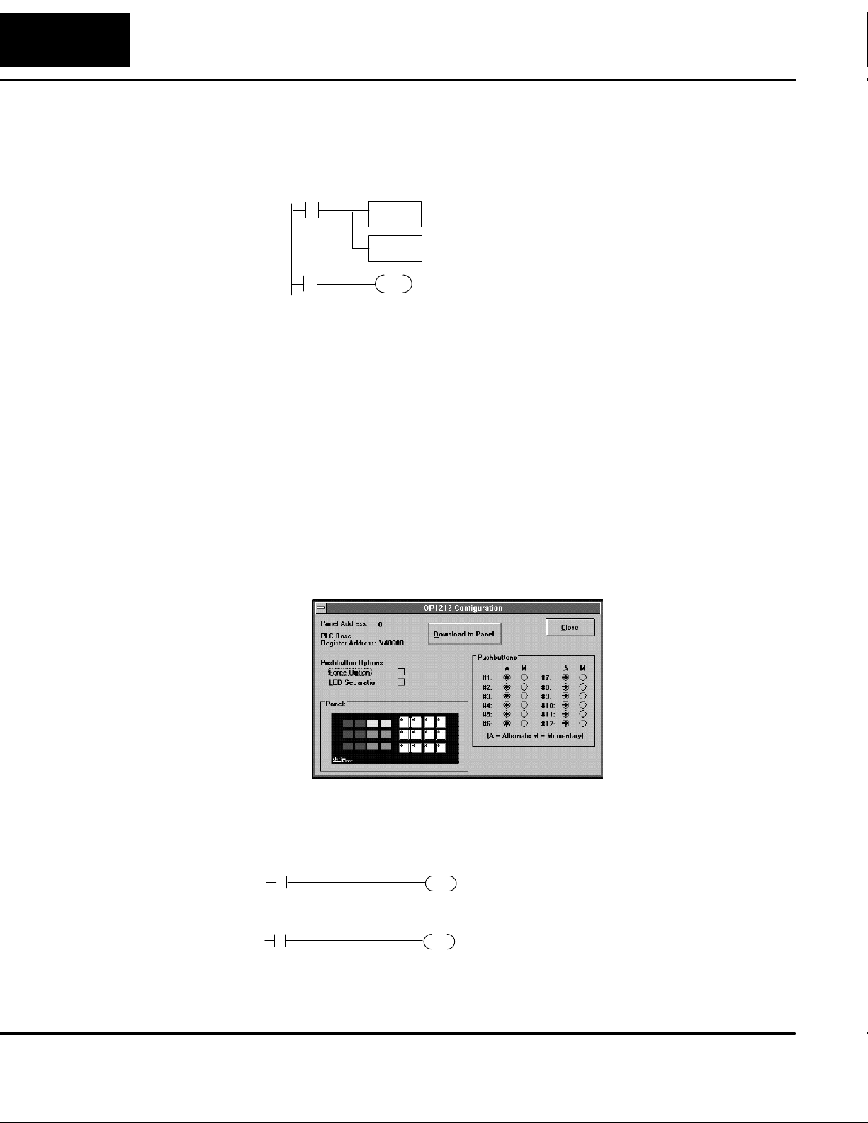
34
Troubleshooting the OP- 1212
D If you are remapping, make sure that you are remapping in the proper
direction and that you are using a contact that is always ON as the input to
the remapping logic. Remapping must be performed every scan to function
properly.
SP1
m+4 =V2004
remapping = V2004:40604
When I activate a bit to light a pushbutton LED, it does not light.
D Verify that you are using the correct address. The base address you chose
during panel configuration determines the proper addresses to use.
D If you are remapping, make sure that you are remapping in the proper
direction and that you are using a contact that is always ON as the input to
the remapping logic. Remapping must be performed every scan to function
properly.
D Verify that LED Separation Mode was enabled during panel configuration.
When I press a pushbutton the associated LED does not turn ON.
D If the LED Separation Mode was enabled, the LED will work independently of
the pushbutton. In this case the LED will be turned ON by the ladder logic
program.
D The pushbutton may be configured as momentary. In this case the LED will
be ON only as long as the pushbutton is being pressed.
C102
LD
V2004
OUT
V40604
Y12
OUT
Here we are using SP1 to map V2004 to V40604.
This consumes 16 relay bits, 12 of which are tied
to the 12 pushbuttons of the panel. By pressing
Pushbutton 3, you affect the status of the third
relay in V40604 which is C102. In turn, C102 will
control output Y12.
I can not make the lamp flash. What could I be doing wrong?
D Remember that to flash a lamp, it must be turned ON first. Verify that you are
turning the Lamp ON before you activated the flashing option.
X13
3
X14
4
Light Lamp 5
Add flashing
C4
OUT
C24
OUT
Rungs 3 and 4 --Flashing Lamps
To flash a Lamp, it must be first turned ON. When
contact X13 is activated Lamp 5 will turn ON and when
contact X14 is activated the Lamp will flash.
Page 41

European Union Directives
x
European Union Directives
This product is manufactured in compliance with European Union (EU) Directives and carries the CE
mark. The following information is provided to comply with EU documentation requirements.
NOTE: Products with CE marks perform their required functions safely and adhere
to relevant standards as specified by EC directives provided they are used
according to their intended purpose and that the instructions in this manual are
adhered to. The protection provided by the equipment may be impaired if this
equipment is used in a manner not specified in this manual. Only replacement parts
supplied by AutomationDirect or its agents should be used. A listing of international
affiliates is available at our website http://www.automationdirect.com.
3535
Technical Support
SELV Circuits
Environmental
Specifications
Preventative
Maintenance and
Cleaning
ternal Fuse
E
Protection
for Input Power
If you need technical assistance, please call the technical support group at
AutomationDirect, Inc. (3505 Hutchinson Rd., Cumming, GA 30040, U.S.A.) at
800--633--0405. Support is available Monday through Friday from 9:00 A.M. to 6:00
P.M. Eastern Standard Time. Our website address is
http://www.automationdirect.com.
All electrical circuits connected to the communications port receptacle are rated as
Safety Extra Low Voltage (SELV).
Operating Temperature 0° to 50° C....................
Storage Temperature --20° to 70° C......................
Operating Humidity 95% (non-condensing)........................
Air Composition No corrosive gases permitted...........................
No preventative maintenance is required. To clean the exterior of the panel
disconnect the input power and carefully wipe the panel with a cloth moistened with
plain water.
There are no internal fuses for the input power circuits, so external circuit protection
is needed to ensure the safety of service personnel and the safe operation of the
equipment itself. To comply with EU specifications, the input power must be fused.
Use a fuse rated at twice the input current rating of the panel. For example, if the
panel has an input current rating of 0.5 amperes, use a fuse rated for 1 ampere.
Page 42

Worksheets
1
A
Page 43

A--2
Worksheets
The following table is a example of the control relay correlation for the DL05, DL06,
DL105, DL205, DL350 or DL405 to the OP--1212 when the address is configured for
V40600. Use the work sheet provided below for the starting address for your
application.
Address 40600
m
Device Lamp ON/
OFF
40601
m+1
Lamp
Flash
40602
m+2
Button
LED ON/
40603
m+3
Button
LED Flash
40604
m+4
Button
Status
40605
m+5
Force
Function
OFF
1 C0 C20 C40 C60 C100 C120
2 C1 C21 C41 C61 C101 C121
3 C2 C22 C42 C62 C102 C122
4 C3 C23 C43 C63 C103 C123
5 C4 C24 C44 C64 C104 C124
6 C5 C25 C45 C65 C105 C125
7 C6 C26 C46 C66 C106 C126
8 C7 C27 C47 C67 C107 C127
9 C10 C30 C50 C70 C110 C130
10 C11 C31 C51 C71 C111 C131
11 C12 C32 C52 C72 C112 C132
12 C13 C33 C53 C73 C113 C133
M3 C135
M2 C136
M1 C137
Address
Device Lamp ON/
OFF
1
2
3
4
5
6
7
8
9
10
11
12
M3
M2
M1
Lamp
Flash
Button
LED ON/
OFF
Button
LED Flash
Button
Status
Force
Function
Page 44

A--3
Worksheets
The following table is a example of the control relay correlation for the SLC or
Micrologix to the OP--1212 when the address is configured for N7:0. Use the work
sheet provided below for your application.
Device Lamp ON/
OFF
Lamp
Flash
Button
LED ON/
Button
LED Flash
Button
Status
Force
Function
OFF
1 N7:0/0 N7:1/0 N72/0 N7:3/0 N7:4/0 N7:5/0
2 N7:0/1 N7:1/1 N7:2/1 N7:3/1 N7:4/1 N7:5/1
3 N7:0/2 N7:1/2 N7:2/2 N7:3/2 N7:4/2 N7:5/2
4 N7:0/3 N7:1/3 N7:2/3 N7:3/3 N7:4/3 N7:5/3
5 N7:0/4 N7:1/4 N7:2/4 N7:3/4 N7:4/4 N7:5/4
6 N7:0/5 N7:1/5 N7:2/5 N7:3/5 N7:4/5 N7:5/5
7 N7:0/6 N7:1/6 N7:2/6 N7:3/6 N7:4/6 N7:5/6
8 N7:0/7 N7:1/7 N7:2/7 N7:3/7 N7:4/7 N7:5/7
9 N7:0/8 N7:1/8 N7:2/8 N7:3/8 N7:4/8 N7:5/8
10 N7:0/9 N7:1/9 N7:2/9 N7:3/9 N7:4/9 N7:5/9
11 N7:0/10 N7:1/10 N7:2/10 N7:3/10 N7:4/10 N7:5/10
12 N7:0/11 N7:1/11 N7:2/11 N7:3/11 N7:4/11 N7:5/11
M3 N7:5/13
M2 N7:5/14
M1 N7:5/15
Device Lamp ON/
OFF
1
2
3
4
5
6
7
8
9
10
11
12
M3
M2
M1
Lamp
Flash
Button
LED ON/
OFF
Button
LED Flash
Button
Status
Force
Function
Page 45

A--4
Worksheets
Use the following template and worksheets to keep track of how you configured the
panel pushbuttons, Lamps and LEDs.
OP--1212 Configuration Worksheet
PLC Type
Panel Address
:_____________
:_____________
1234
567
9101112
8
1234
5678
9101112
PLC Base
Register Address
:_____________
Pushbutton Options
Link Configuration:
Protocol _____________________
Baud Rate ________________
Parity _______________
Stop Bit ____________
Force Option
LED Separation
AM AM
#1
#2
#3
#4
#5
#6
#7
#8
#9
#10
#11
#12
(A = Alternate M = Momentary)
Lamp Descriptions
1._______________________________ 7.______________________________
2._______________________________ 8.______________________________
3._______________________________ 9.______________________________
4._______________________________ 10._____________________________
5._______________________________ 11._____________________________
6._______________________________ 12._____________________________
Pushbutton Descriptions
1._______________________________ 7._______________________________
2._______________________________ 8._______________________________
3._______________________________ 9._______________________________
4._______________________________ 10.______________________________
5._______________________________ 11.______________________________
6._______________________________ 12.______________________________
LED Descriptions
1._______________________________ 7._______________________________
2._______________________________ 8._______________________________
3._______________________________ 9._______________________________
4._______________________________ 10.______________________________
5._______________________________ 11.______________________________
6.__________________________ 12.____________________________
__
Page 46

Index
1
A
Address
assigning a hardware address, 15
conventions, 20
setting the dip switch, 15
Addressing conventions, 20
B
Bezel, 5
Bit-of-Word, 22
C
Cable requirements, 9
cables, 10
shielded cable, 12, 13
Communications Master, 9
Connector specification, 10
Programming cable, 10
Connector specifications, 12, 13
PLC-to-Panel cable, 10
D
DCM, 12, 13
DCU, 12, 13
Dimensions for mounting, 8
DirectSOFT, 2
G
GE Series 1, 12, 13
I
Internal Relays, 22
L
Labels, 5
Preparing labels, 5
Templ ate, 5
Legend, 5
Control relays, 24, 25, 27. 29
Cutout area for panel, 8
M
Memory mapping, 17
N
NEMA, 7
Page 47

Index--2
O
Octal numbers, 24, 25
OP-9001, 9,16
OP-CMCON-1, 12, 13
OP-CMCON-2, 12, 13
P
Power supply, 14
Product support, 17, 18
R
Remapping, 22, 26
Ribbon cable, 9
RS422, 16
S
SIMATIC, 12, 13
SLC500, 12, 13
5/03, 12, 13
Slice I/O, 12, 13
Specifications, 7
T
Termination resistor, 15
TI305, 12, 13
TI405, 12, 13
 Loading...